Arduino Mega Based In-Circuit Tester Setup
Software installation, build and programming.
Arduino Development Software - Installation
The Arduino software can be downloaded from http://arduino.cc/en/Main/Software.
Using the Windows Installer option leave all the options as they are set by default. When the USB driver install pops up click to install
the USB driver.
Arduino Development Software - Configuration
Launch the Arduino software. If you get a "Windows Firewall has blocked..." pop up then select the Allow options for network access
(usually "Domain" & "Private" at least) and then "Allow access". In the Arduino environment perform the folowing configuration:
- Select the board using the Tools menu: Tools->Board->Arduino Mega or Mega 2560
- Select the sketchbook location using the File menu: File->Preferences "Sketchbook location:" box. In my case I use my OneDrive
location for an automatic backup, e.g. C:\Users\{name}\OneDrive\Arduino.
- Tick the "Automatically associate .ino files with Arduino" box.
In-Circuit Tester Software - Installation
Unzip the in-circuit tester software package into the "Sketchbook location:" configured above. This gives a layout as follows:
C:\Users\{name}\OneDrive\Arduino\InCircuitTester2650
C:\Users\{name}\OneDrive\Arduino\InCircuitTesterZ80
C:\Users\{name}\OneDrive\Arduino\libraries
In-Circuit Tester Software - Build
- Double click one of the .ino project that should open the Arduino project for that CPU (e.g.
C:\Users\{name}\OneDrive\Arduino\InCircuitTester2650\InCircuitTester2650.ino).
- Build the project using the Sketch menu: Sketch->Verify / Compile. The lower window should show "Done compiling"
in the title bar when it's finished.
In-Circuit Tester Software - Download/Programming
- Connect the Arduino Mega to the host PC using the USB cable supplied with the Arduino.
- Select the USB port from the Tools menu: Tools->Port->COMx
- Upload the in-circuit test software using the File menu: File->Upload. The lower window should show
"Done uploading" in the title bar when it's finished.
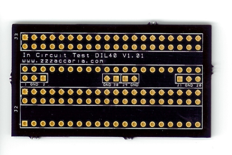
In-Circuit Tester Probe Head - Jumper Settings
There are 2-pin GND jumpers that must be inserted into positions that match the CPU under test:
| CPU | Jumper |
 |
| Z80 | 29-GND |
| 8085 | GND-20 |
| 2650 | 21-GND |
| 6502 | 1-GND & 21-GND |
| 6801 | 1-GND |
| 6809 | 1-GND |
| 6800 | 1-GND & 21-GND |
| V30 | GND-20 |
| 8035 | GND-20 |
| 6701 | GND-30 |
| INS8900 | GND-30 |