Hantarex MTC-90 to MTC-900 Conversion
I had been battling with Hantarex MTC-90 monitors that were fitted to three of my games over three or so years. I'd accumulated a
lot of spare boards & parts to continue to keep them running but their reliability had been poor and they'd been awkward to fix being
difficult to remove and hard to diagnose. In show, the monitors had not fared well with only one game making it through one show in
three years of submissions. With a heavy heart I reached the conclusion that the MTC-90 was just too poor a chassis to continue to try
and maintain and thus began this project to replace the MTC-90 chassis with a next generation MTC-900 chassis preserving the existing
CRT & frame in the cabinet.
Chassis CRT Compatibility
I'd accumulated a few spare MTC-900 chassis and began the project by looking in the manuals for the CRT configuration information. The
base schematic in the MTC-900 and MTC-90 manuals was for use with an ITT A51-211X CRT. The MTC-90 used the "MV" neck board and the
MTC-900 used the "FB" neck board.
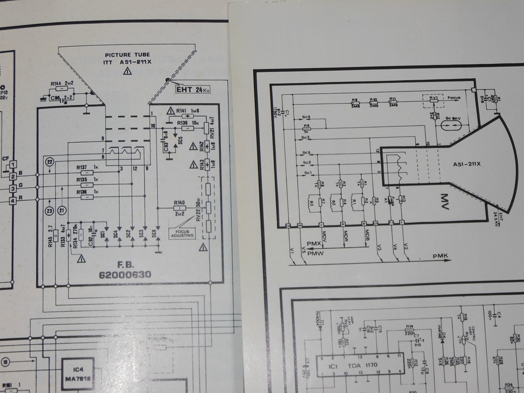
Checking with what was actually fitted in the cabinets confirmed that all my MTC-90 monitors used the ITT A51-211X CRT.
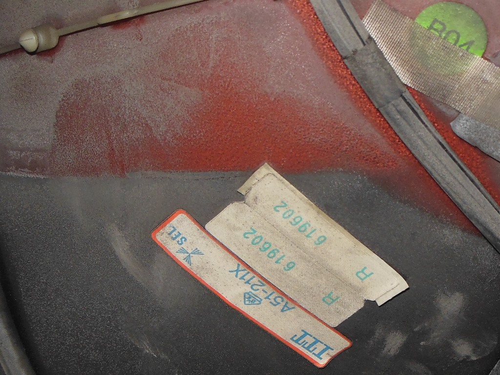
The yoke was sealed to the CRT so it was almost certain that the MTC-90 & MTC-900 CRT's were identical and thus a MTC-900 could support
the MTC-90 CRT. I'd already discovered an MTC-900 CRT configuration chart stapled into some cabinets that outlined the chassis
configuration for various CRT. The first row covering 20" ITT on the "FB" neck board was likely the one matching the ITT A51-211X and
the configuration needed for this conversion.
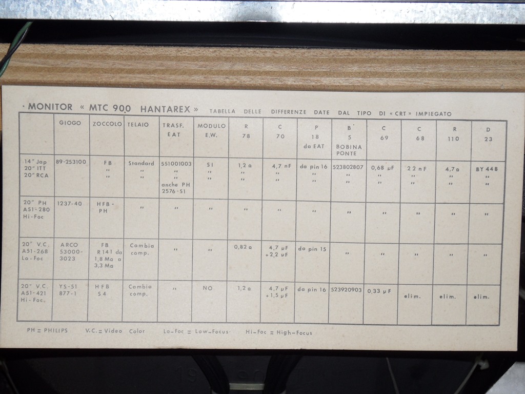
Based on my stocks of MTC-900 chassis the list above appears to be missing an additional configuration. I've seen two configurations of
"S4" based MTC-900 chassis, one with East-West and one without. The chart above does not show an "S4" configuration without East-West.
Inspecting a few "S4" complete monitors found that these were using ITT A51-231X CRT. My theory is that these are the same
yoke configuration as the -211X but with "S4" neck assemblies and therefore I could use one of these chassis with an "FB"
neck board for use with a -211X if I can't find complete "FB" chassis in future.
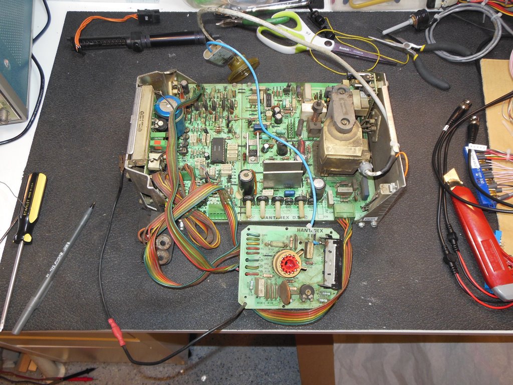
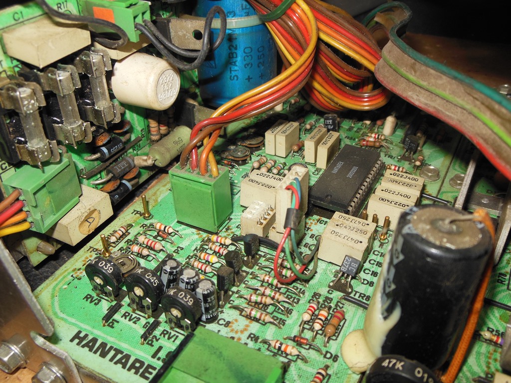
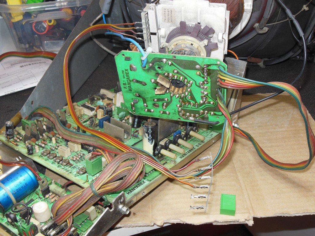
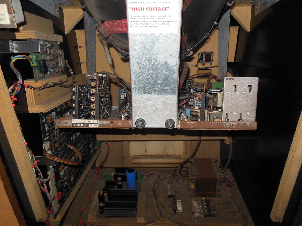
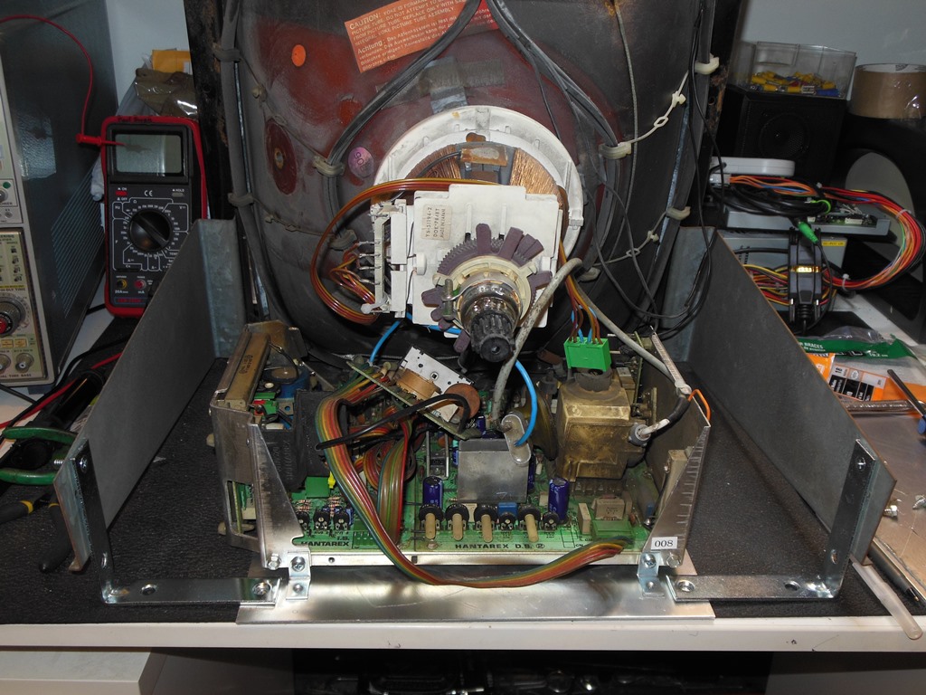
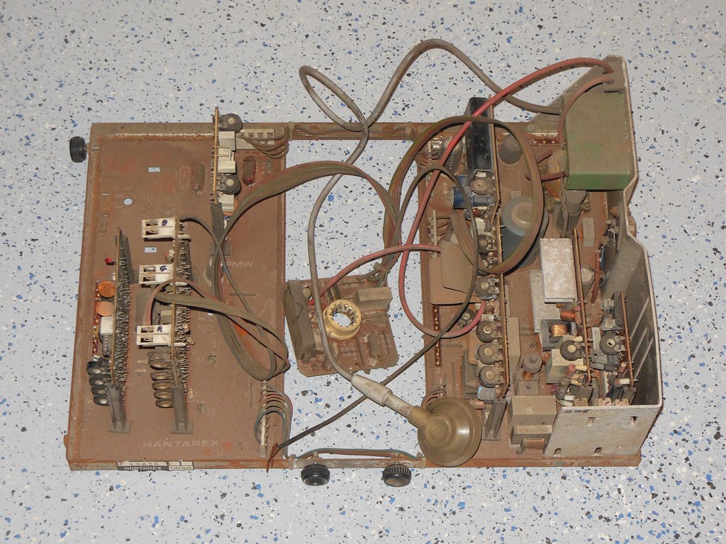
Hantarex MTC-90 "FB" Chassis Repair
Though I had a lot of spare chassis I had only one hacked up chassis that used the standard focus "FB" neck board with almost all
the remainder using the high focus "S4" neck board. Therefore, the first step was to clean up and repair this "FB" chassis.
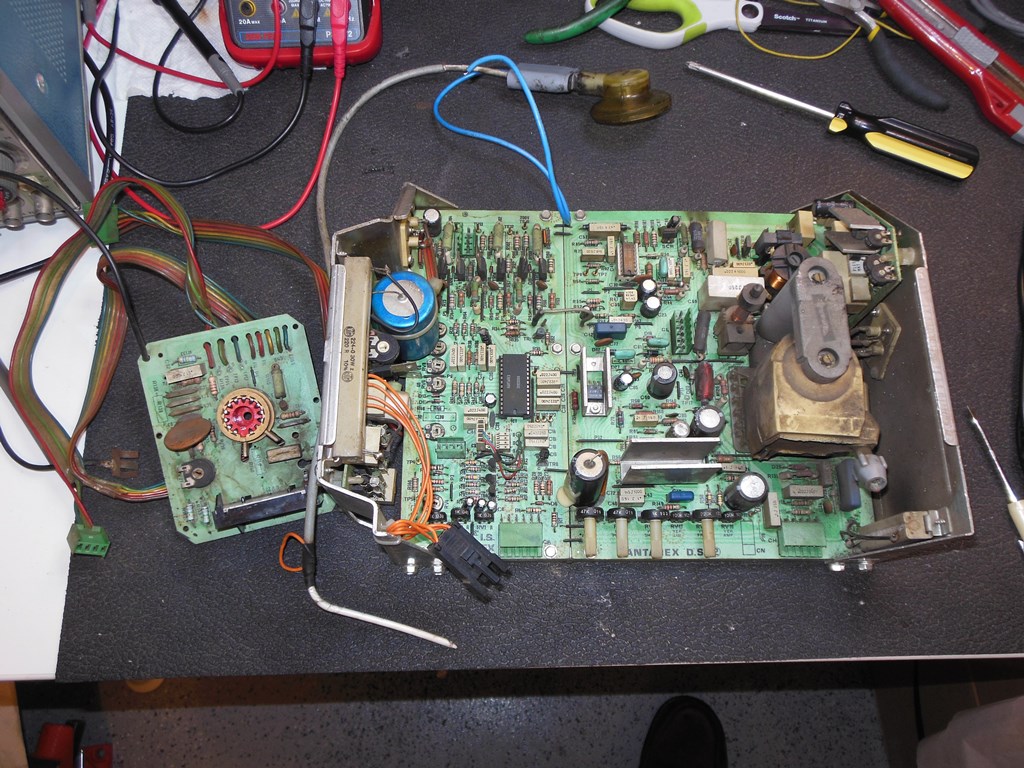
The laundry list of things to clean up was:
- Restoration of the original power connector.
- Reconnection of the HV lead.
- Addition of a missing resistor on the neck board.
- Addition of the missing brightness/contrast control assembly.
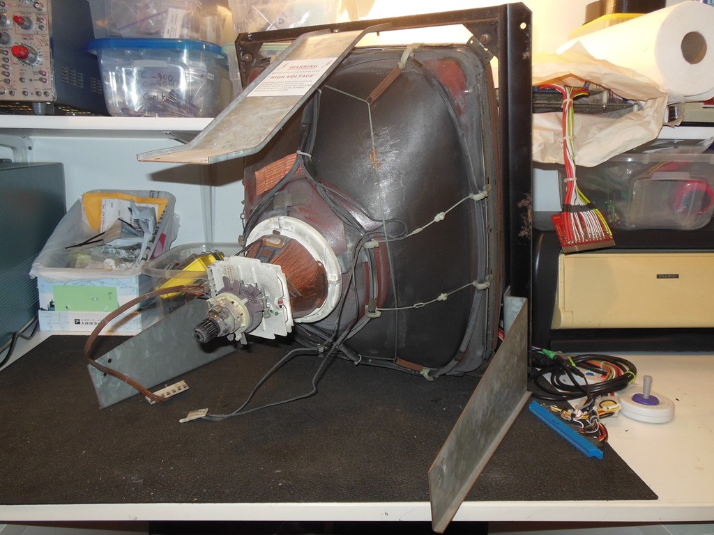
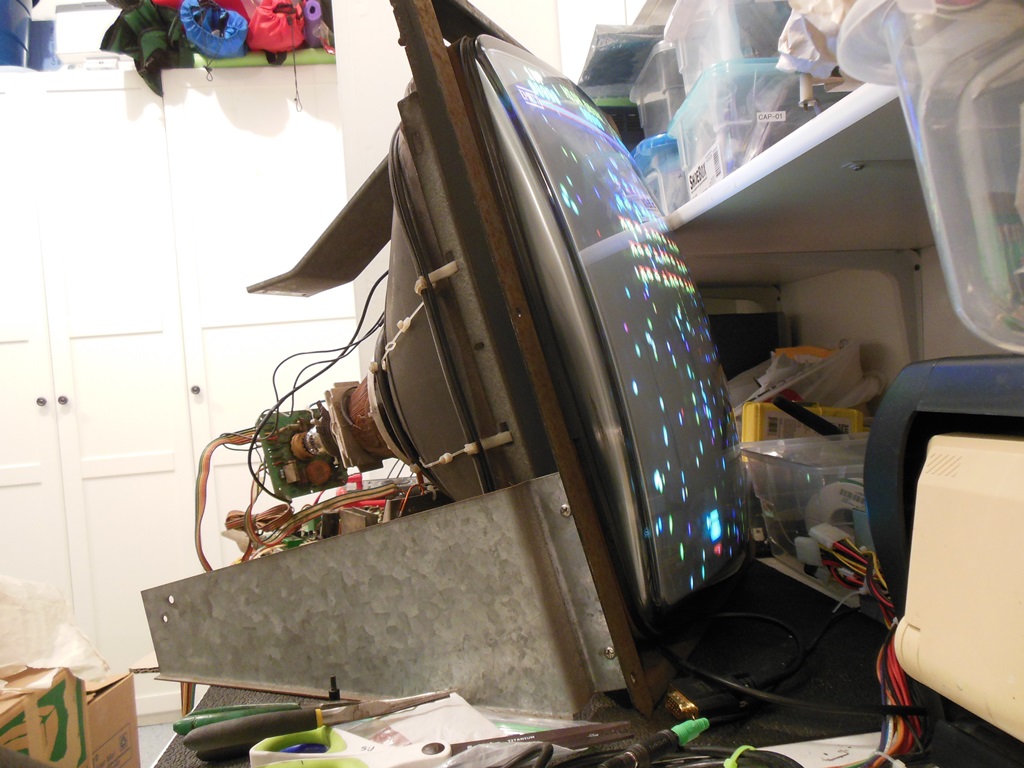
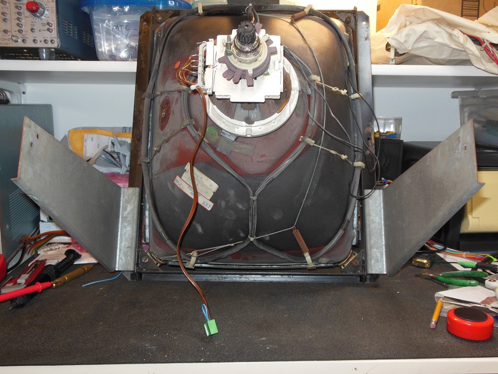
With the obvious problems with the chassis cleaned up the next step was to setup a spare MTC-90 CRT on the bench and hook it up.
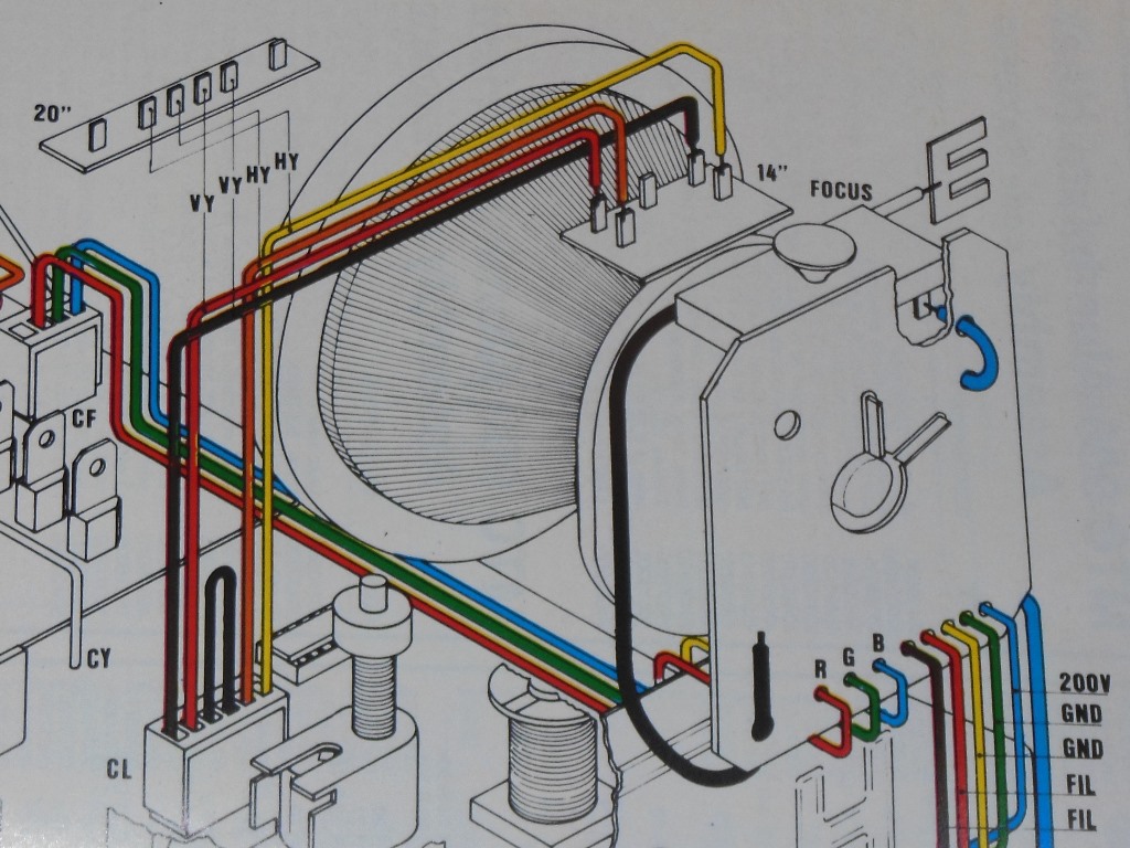
MTC-90 CRT Testing with MTC-900 FB Chassis
I had a spare MTC-90 CRT left in one of the Duke of Lancaster Astro Wars cabinets that I could use for testing on the bench.
The manuals provided the wiring information on how the two chassis connected to the yoke. Initial testing only needed the
vertical & horizontal pairs identifying to get a picture. Figuring out the orientation could come later.
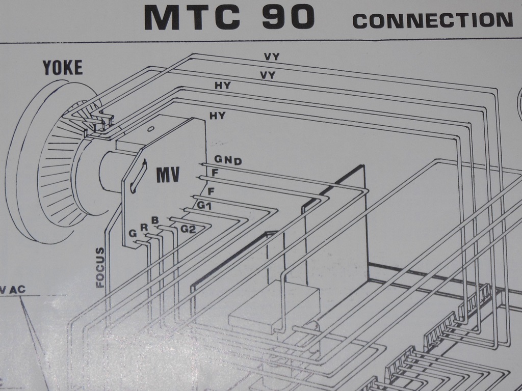
In both diagrams "VY" identifies the Vertical Yoke and "HY" identifies the Horizontal Yoke.
For initial testing I had a spare recycled yoke cable set I could use to patch into the existing MTC-90 yoke connector.
Wire patching the yoke connector and fitting the chassis onto the CRT was straight forward.
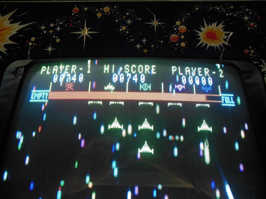
First power on yielded an upside down but good picture :)
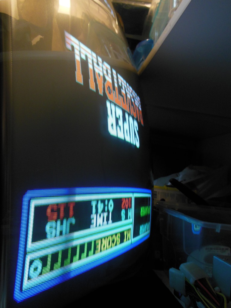
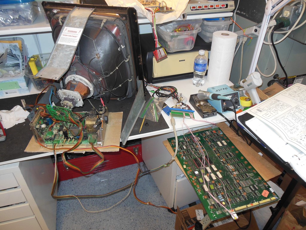
Testing with Galaxia
My "Super Basketball" test PCB is conventional output but this chassis would be used in Astro Wars & Galaxia that both output
inverted video. The Hantarex MTC-900 supports inverted video inputs by moving a selector plug on the chassis.
The picture below shows the normal video option plug.
The picture below shows the inverted video option plug.
Adding Galaxia to the test setup took up a lot of space.
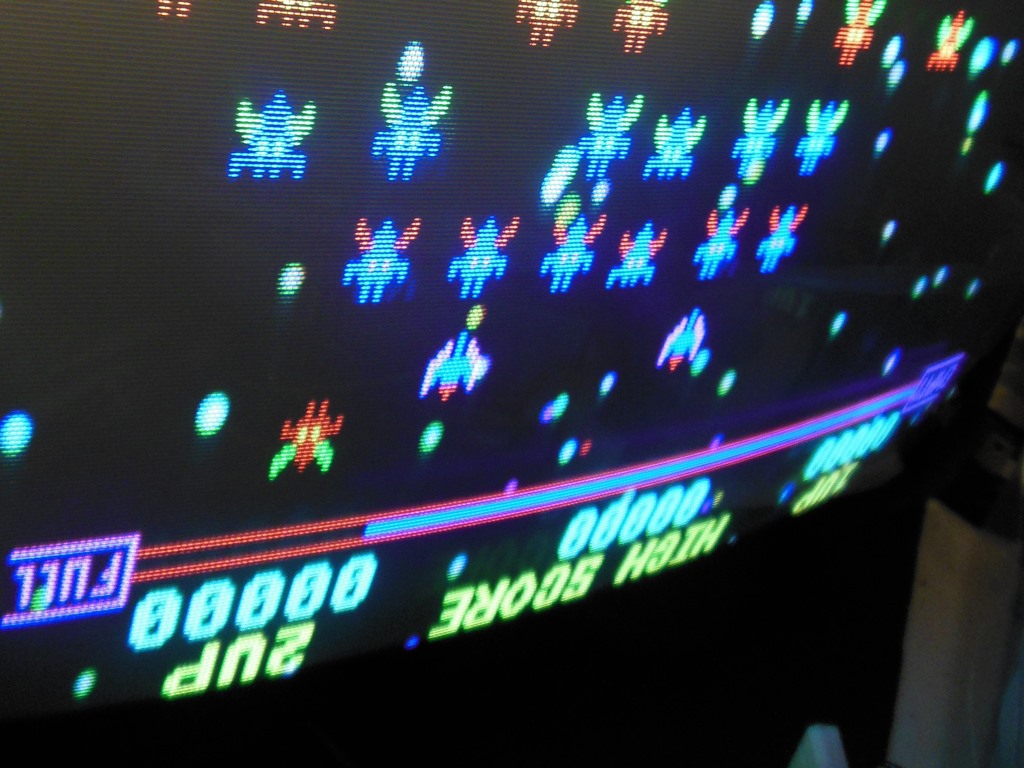
The inversion option appears to match perfectly with this platform :). Note that the colours are incorrect because the video
pinout for Quasar has red and green swapped compared to Galaxia and I'm using my Quasar adaptor to run this board on then
bench.
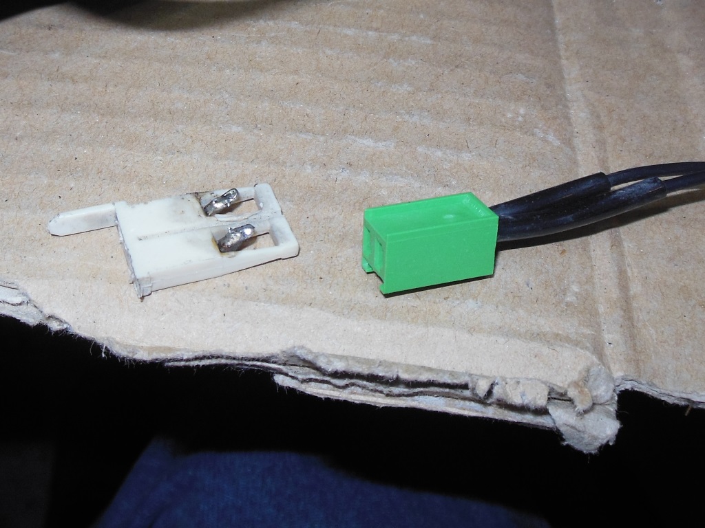
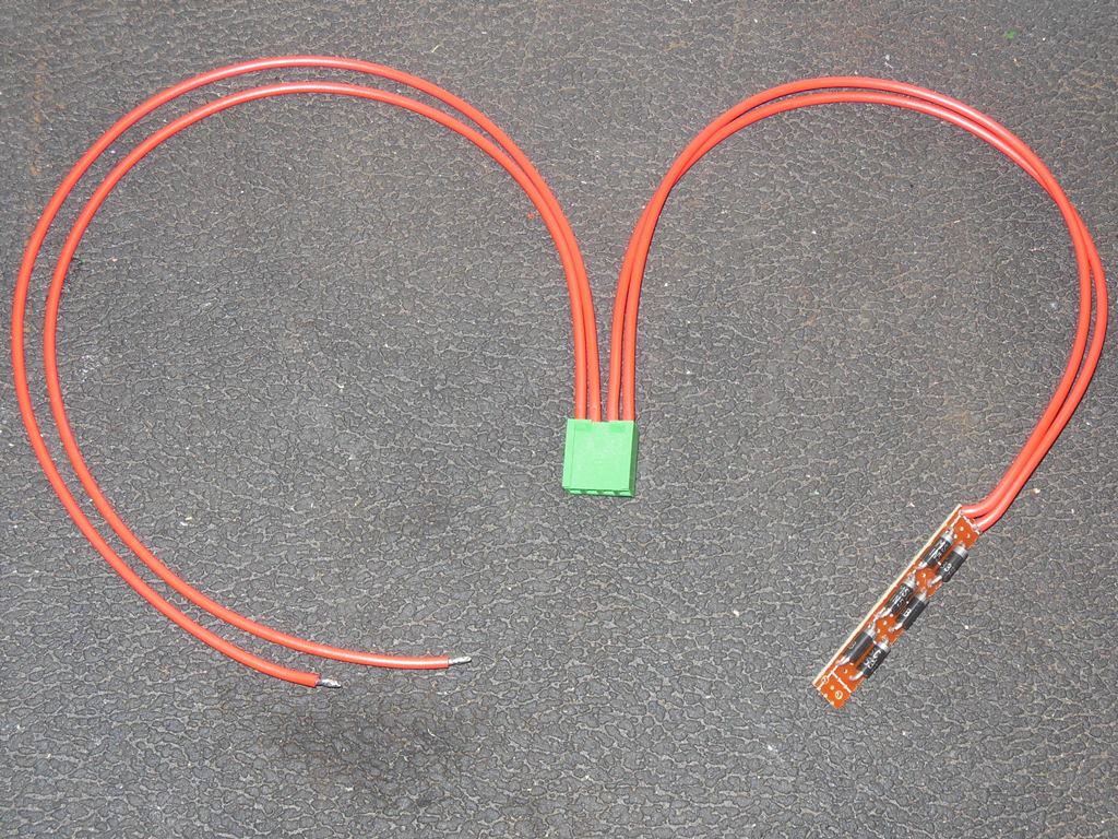
Changing the Yoke Connector
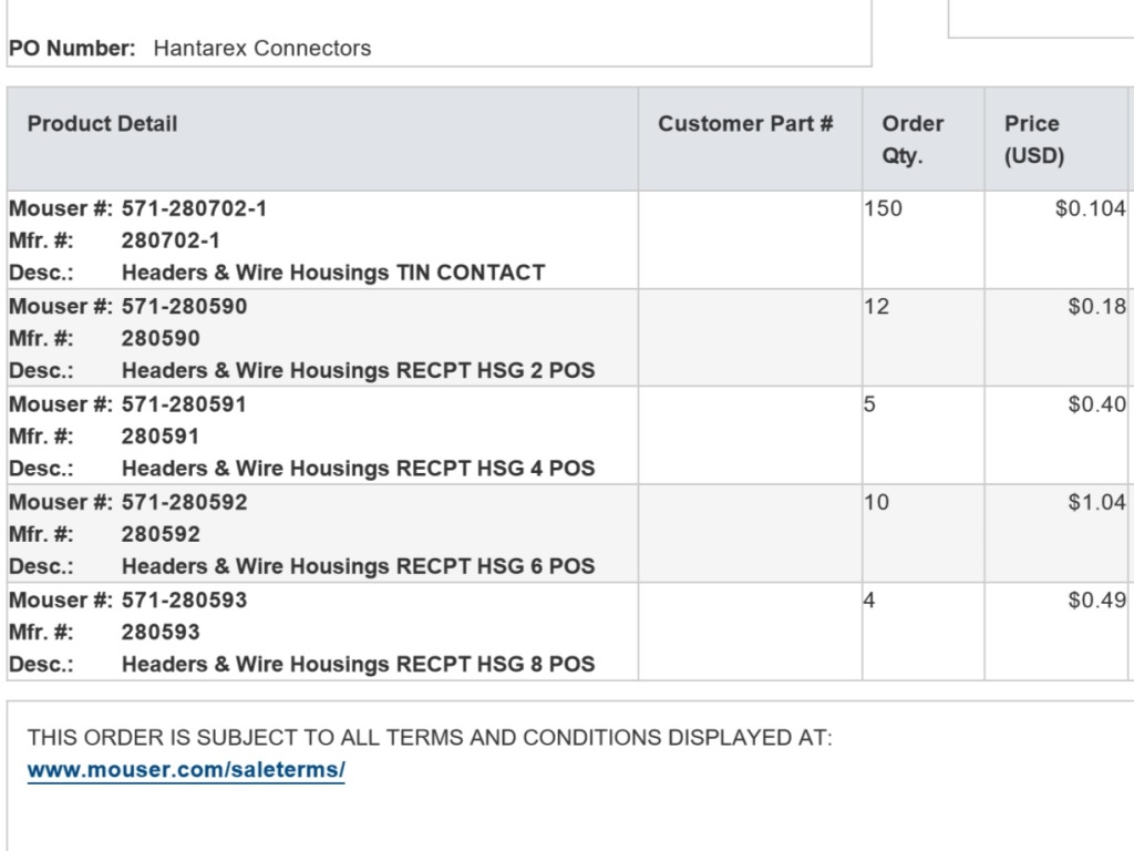
The green Hantarex connectors are still widely available - they are AMP MODU I connectors now made by TE Connectivity and
I was able to get them from Mouser.
My personal preference is to hand crimp and solder machine crimped pins since the right crimping tools are hard to get and
expensive.
I followed the wiring from a recycled yoke cable I already had to make it match. I noticed that the yoke wiring is
inconsistent - some yoke cables are crossed at the connector rather than on the yoke so there is a little investigation
needed to get the picture orientation (flip & mirror) correct. In this case, the initial testing above showed a direct view
but upside down picture and thus horizontal & vertical needed to be crossed (flipping the picture causes a mirror so
vertical also needs to be swapped to compensate). This is safe to do but the horizontal pair must never
be crossed with the vertical pair!
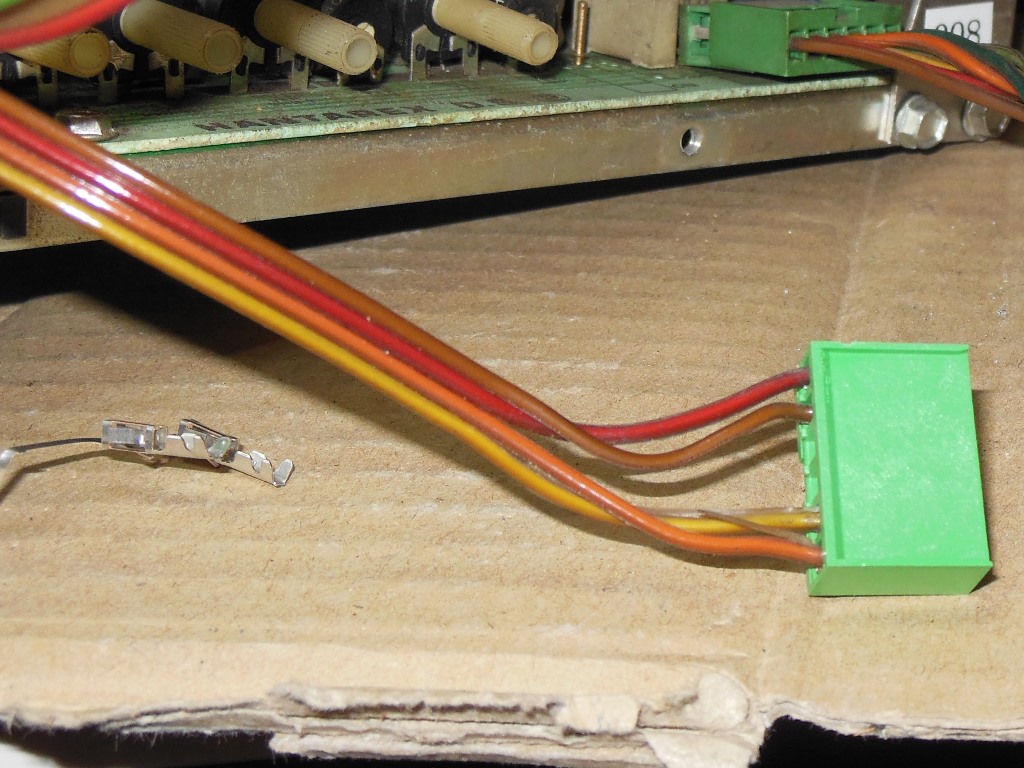
The last part was to make the center loop. Other than different wiring colours the replacement connector is the same as the
original.
Changing the Degauss Connector
There is no specific pin ordering on the degauss connector making it a simple case of changing the MTC-90 one for an MTC-900
one.
I chose to preserve the two sleeves on the cable.
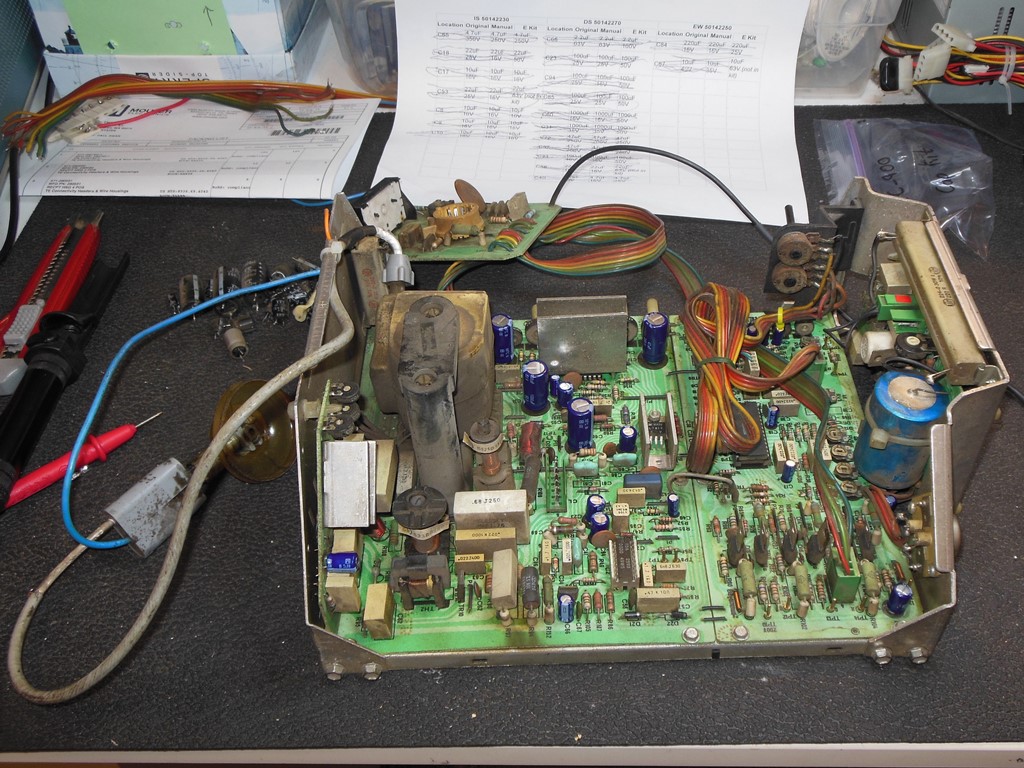
Retest with Finalized Wiring
With the finalized CRT wiring in place I retested to confirm that the picture flip had worked and everything still looked OK.
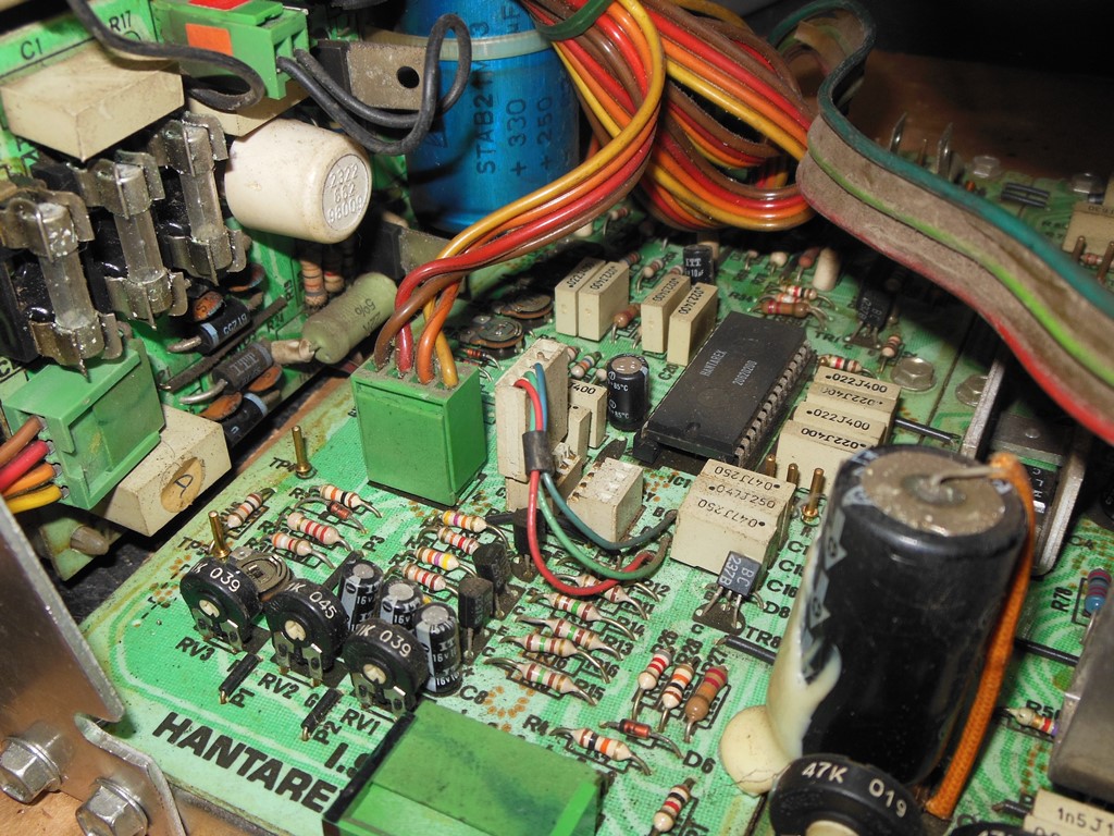
MTC-900 Cap Kit
There were a couple of caps that looked swollen and a wobbly glued axial in place of a radial that I decided to clean up with
a cap kit. MTC-900 cap kits are not generally available but I have some homemade sets ready to use.
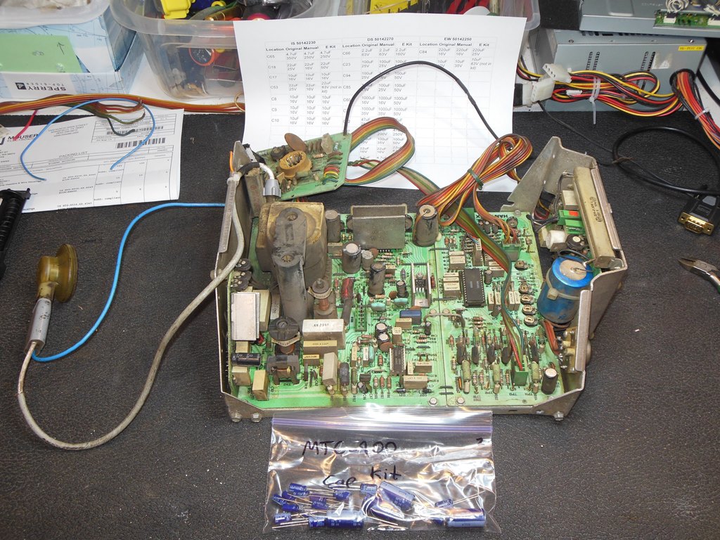
Nothing unusual with applying the cap kit.
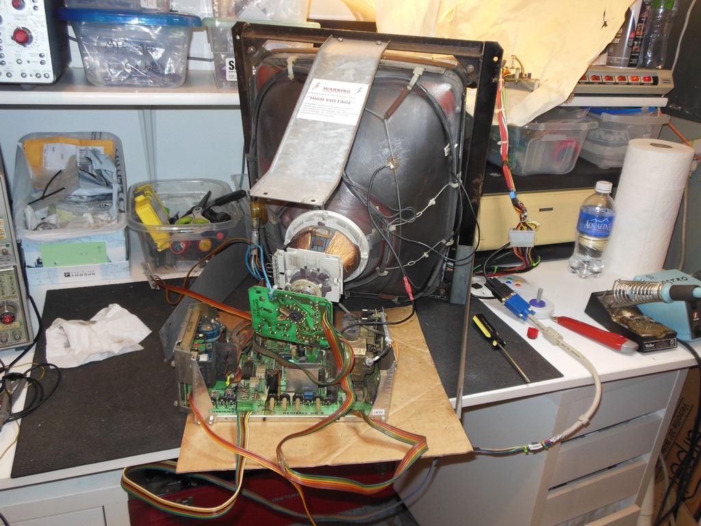
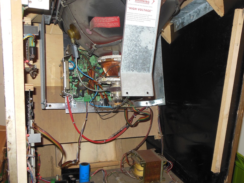
Creating a Chassis Mounting Plate
Getting a compatible MTC-900 chassis to run the MTC-90 CRT was one part of the project. The next part of the project was to
figure out how to mount the MTC-900 chassis into the MTC-90 frame in a non-destructive but secure way that would work when
fitted into the cabinet. The way the MTC-90 chassis was mounted didn't look like a viable option for the MTC-900 chassis.
I investigated if it was possible to go with something similar to how the MTC-900 is mounted into its native frame, i.e. mount
the chassis on a metal plate under the yoke/neck at the bottom of the CRT. To do that I'd need some way to attach at least two
ends of the plate at the front of the frame and at the back.
The front frame around the CRT has a metal lip all the way around and it looked like a metal plate at the right angle could
slide into it between the CRT and the lip of the front frame. At the back the two side arms were both the wrong angle and
spread out too far away to be able to attach a plate at the back, needing some sort of bridge metalwork to attach it.
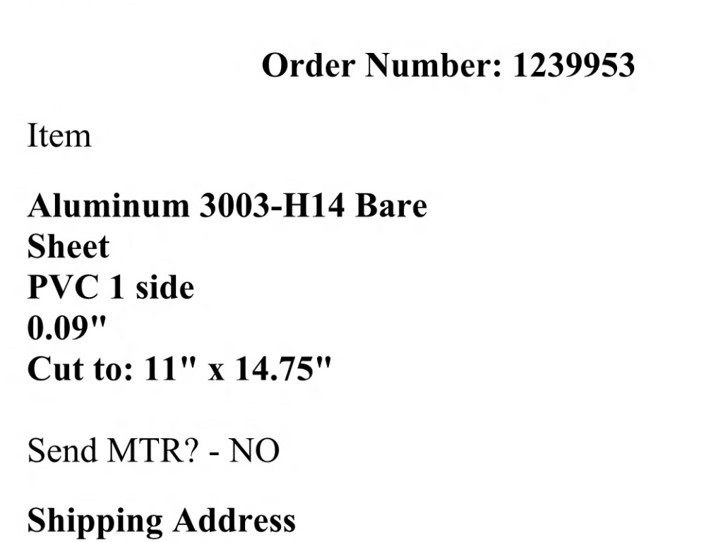
Measuring the distance between the mounting frame angle supports at the front such that the plate would be narrow enough to
slide through gave a width of 11". The distance from the front of the frame lip to the back edge of the two side
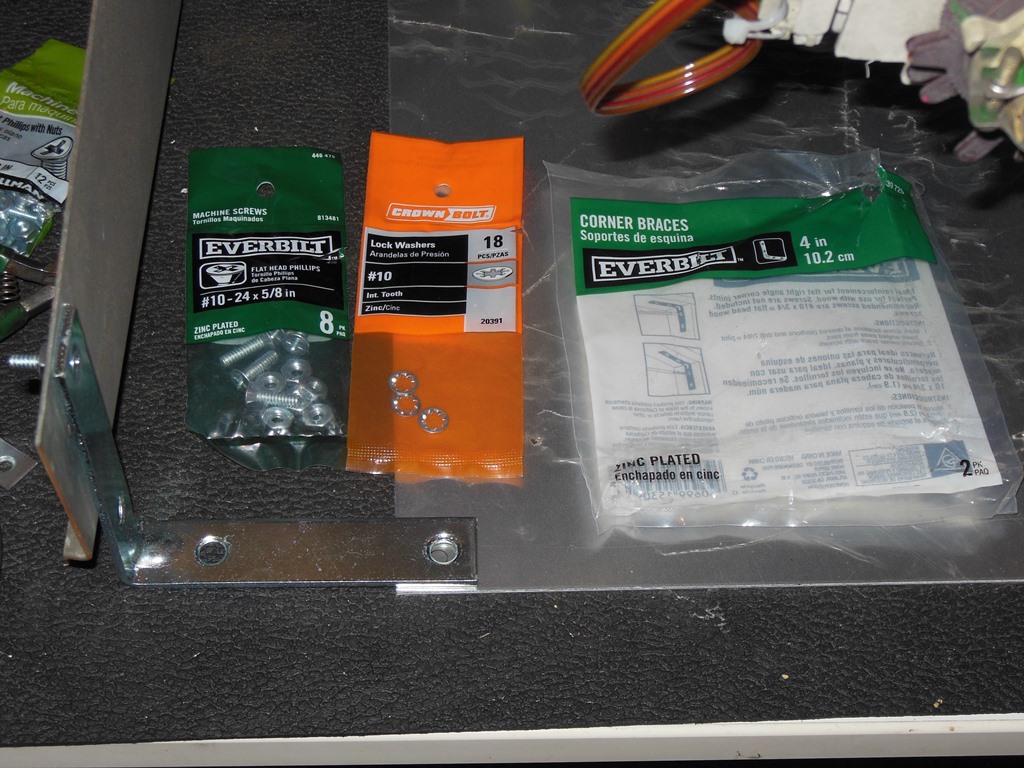
arms was 14.75". I ordered sufficient plates from OnlineMetals to make up four conversions.
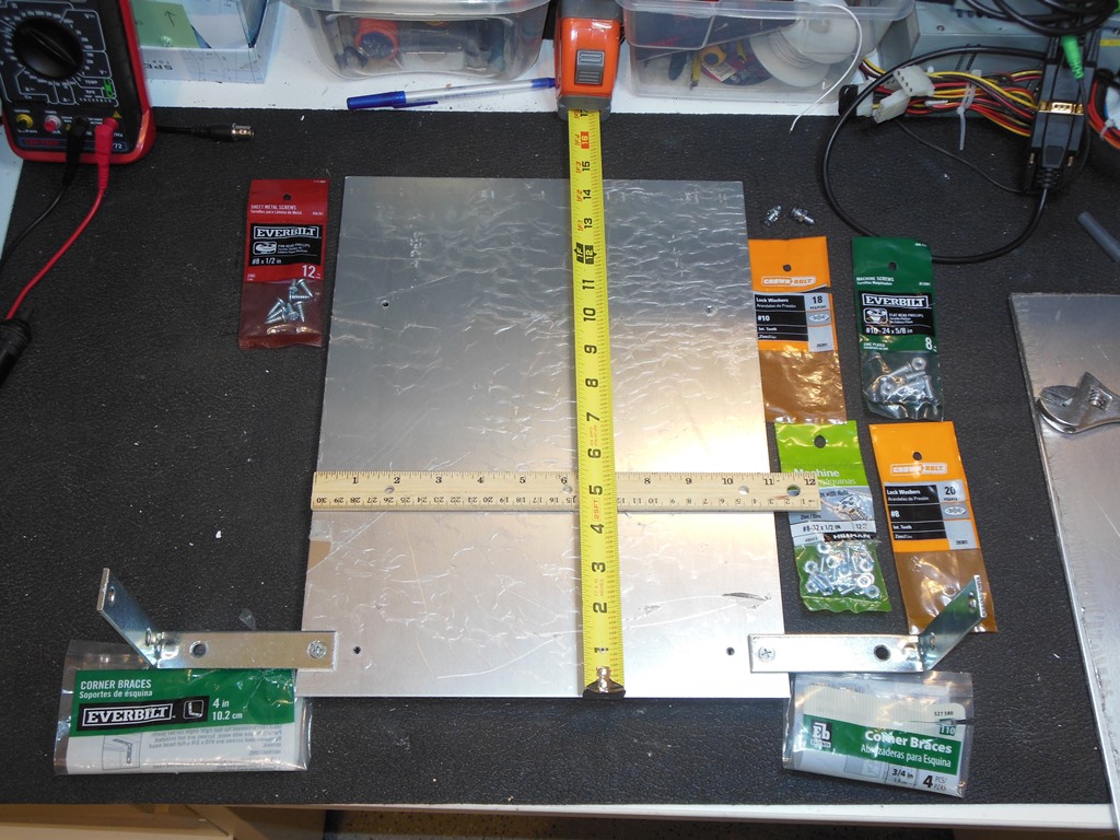
The 11" width of the plate left a gap between the plate and the two side arms. A visit to The Home Depot turned up a couple
of 4" L brackets that seemed to be the right size along with nuts & bolts to attach them.
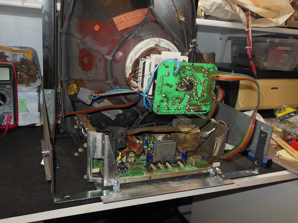
The usual way an MTC-900 chassis is mounted is by slipping it into two prongs in the base plate at the CRT end and
securing it in place at the neck end with a pair of thumbwheel screws. Since my base plate was flat with no mounting punch
outs I needed to find an alternative way to mount the chassis to the base plate. The chassis has two side assemblies that
are secured with a pair of screws at each end. I found that I could buy slightly longer but thread compatible replacement screws
and use those to attach four small 0.75" L brackets to mount the chassis to the base plate. Staging this on the bench confirmed that
all the pieces fit together.
Drilling out the holes and bolting everything in place confirmed that the mounting was secure. One side effect is that the
chassis is harder to remove from the base plate because it's bolted down and the bolts under the CRT are hard to get to.
However, because the base plate itself is only secured at the back with the two bolts into the 4" L brackets it's easy to
remove the chassis with the plate together.
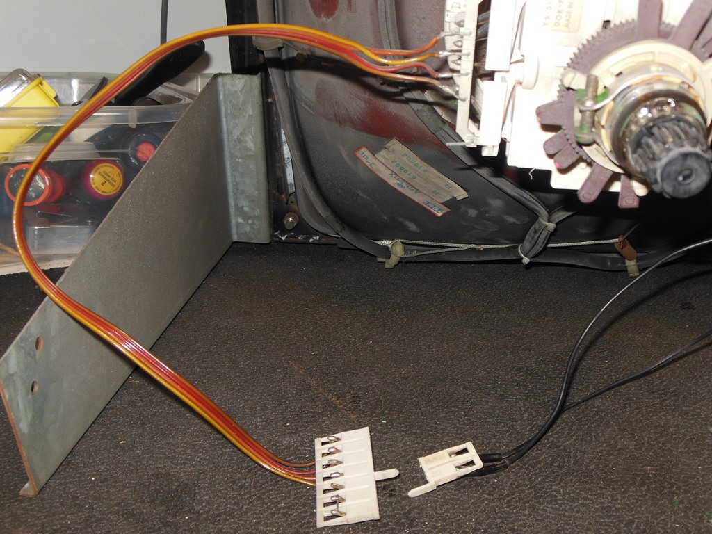
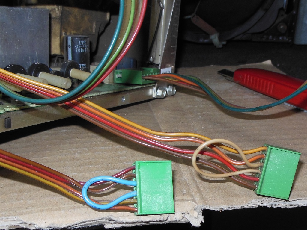
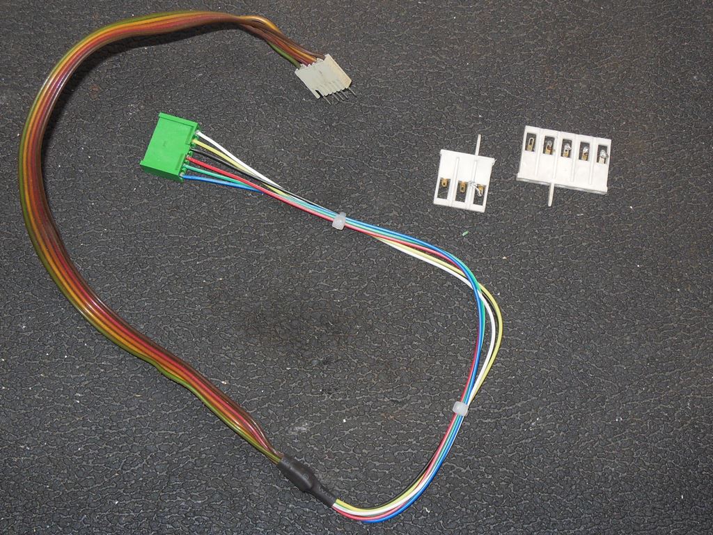
Cabinet Wiring Adaption
In the cabinet the existing MTC-90 connectors needed to be replaced with the equivalent MTC-900 connectors on both the CRT side
and the chassis input side. On the chassis input side, I needed to make up a power cable and a video cable to splice onto the
existing wiring. The video input connector was slightly more complicated to make than the power connector and I used strands
from a ribbon cable to provide the correct colour wires for the cable to make it easier to splice into the cabinet.
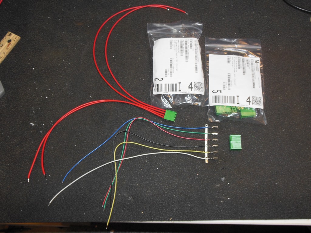
The power input connector cable was made with thick gauge high insulation cable. The yoke cable I made up separately on the bench
so that it would be easy to replace on the yoke rather than trying to replace the connector in the cabinet.
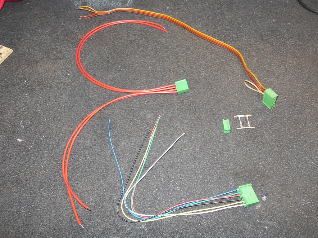
The video cable is free hanging in the cabinet and is easily removed as a result.
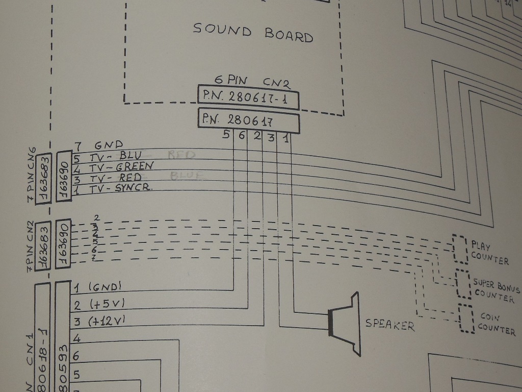
The video cable is the most complicated to wire in and the Astro Wars cabinet manual provides the pinout for this.
The existing MTC-90 video connectors were simply unsoldered on the bench.
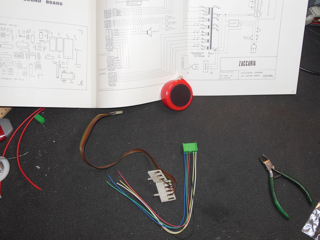
Splicing in the MTC-900 video cable assembly and securing each connection and the group with heat shrink tubing completed
the assembly.
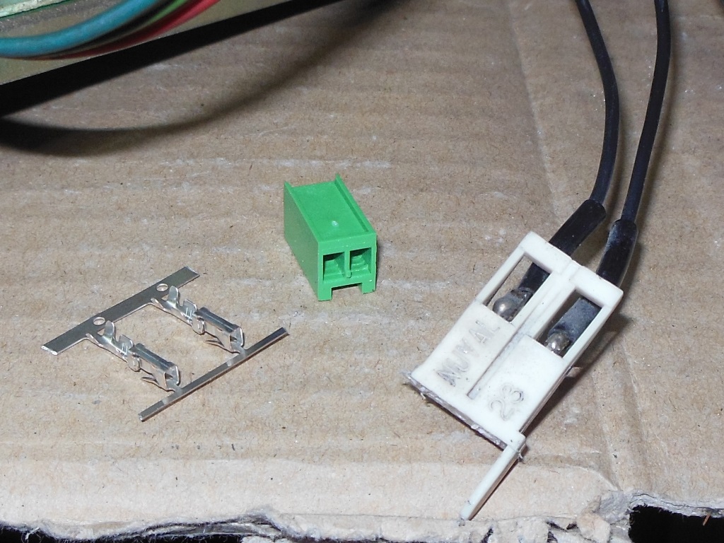
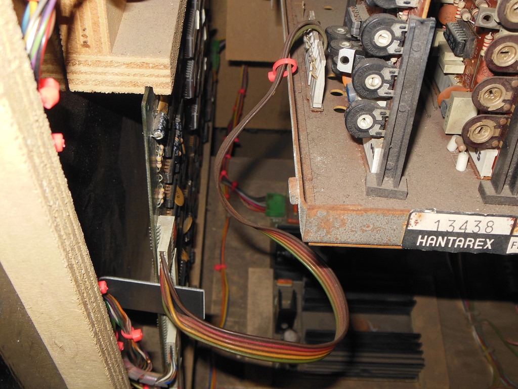
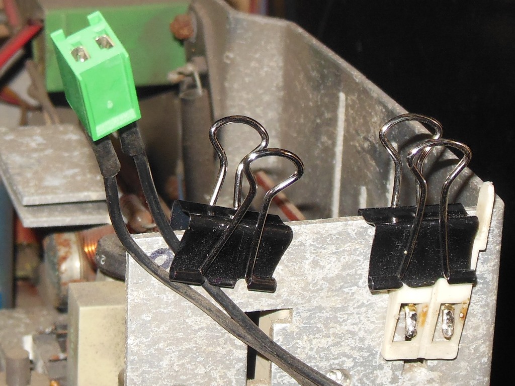
The two-pin degauss connector had to be done in the cabinet and the MTC-90 frame with a binder clip served as helping hands to
do that.
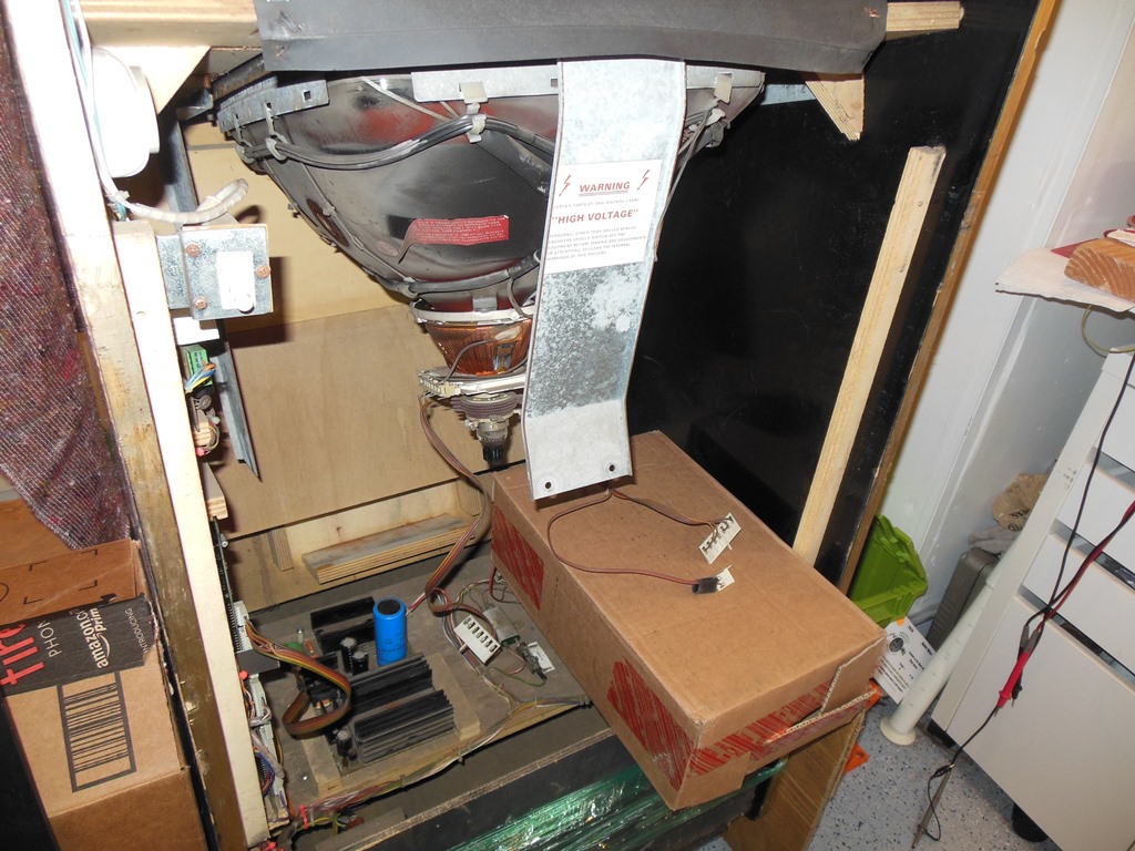
The time had come to remove the original MTC-90 from the cabinet to be able to get at the yoke & power cables.
The MTC-90 chassis I kept for spares since many of the components on it are used on later models (BF871, focus pot etc.).
Power Supply Adaption
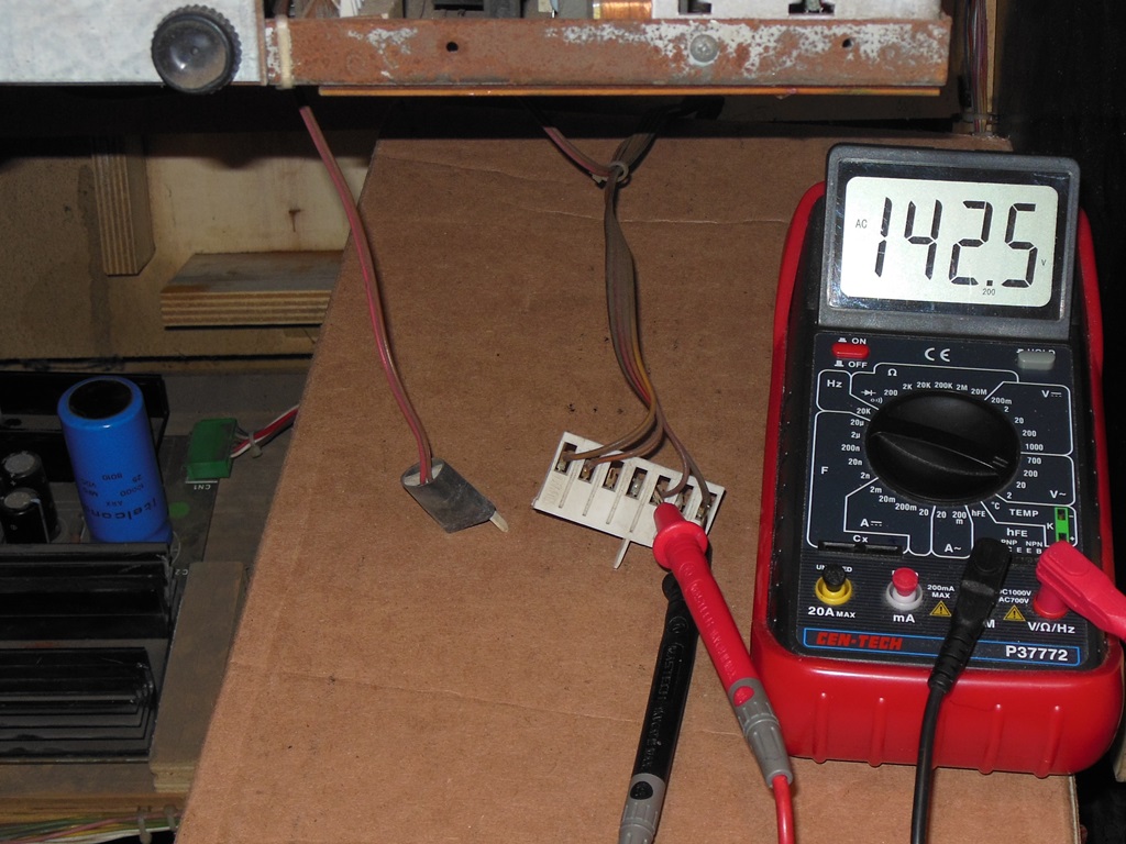
There was also one additional complication in the cabinet that needed to be addressed - the MTC-90 operates
from 143VAC but the MTC-900 operates from 128VAC, according to the respective manuals. Verifying the no-load AC voltage on the
143VAC registered 142.5VAC on the meter.
Verifying the no-load AC voltage on the 220VAC registered 210VAC.
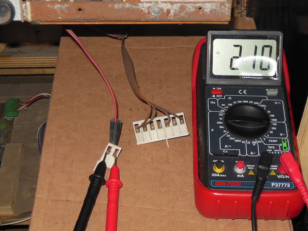
As expected the 220VAC was OK as is but the 143VAC was a bit high - the MTC-900 manual states a maximum supply voltage
of 139VAC. There are a couple of options for solving this problem, the first being to fit a standard Hantarex 220V to 128V
isolation transformer tapped of the existing 220V line. The second option was to "drop" the 143VAC down to 128VAC in a controlled
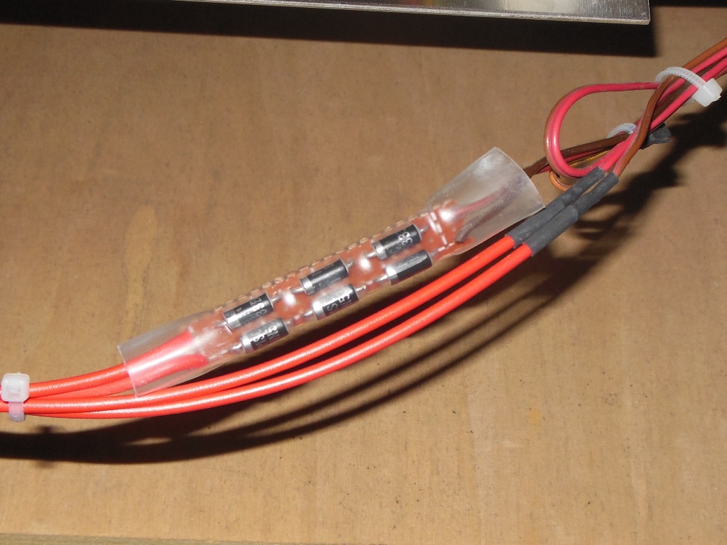
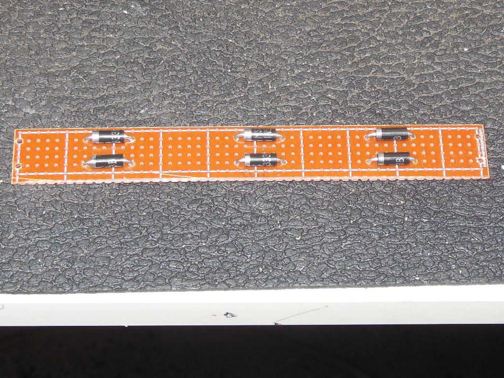
way. I came up with a solution based on using two runs of three back to back 3.3V 5W Zener diodes. The three forward diodes
would yield a 3 x 1.0V drop and the three reverse diodes a 3 x 3.3V drop, giving a total of ~12.9V drop bringing the AC supply
down from 143VAC to ~130VAC. The maximum power dissipation of 5W sets a maximum reverse current capacity of 5/3.3 = 1.51A
and a maximum forward current capacity of 5/1.0V = 5A. Taking both half waves together would give on average ~3.2A maximum.
Since the MTC-900 has a 2A fuse in this supply this arrangement looked reasonable on paper with a likely total operating power
dissipation inside the cabinet of about 15W.
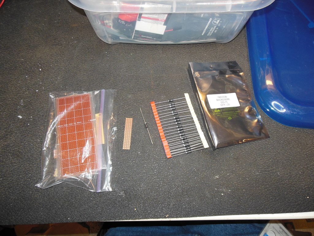
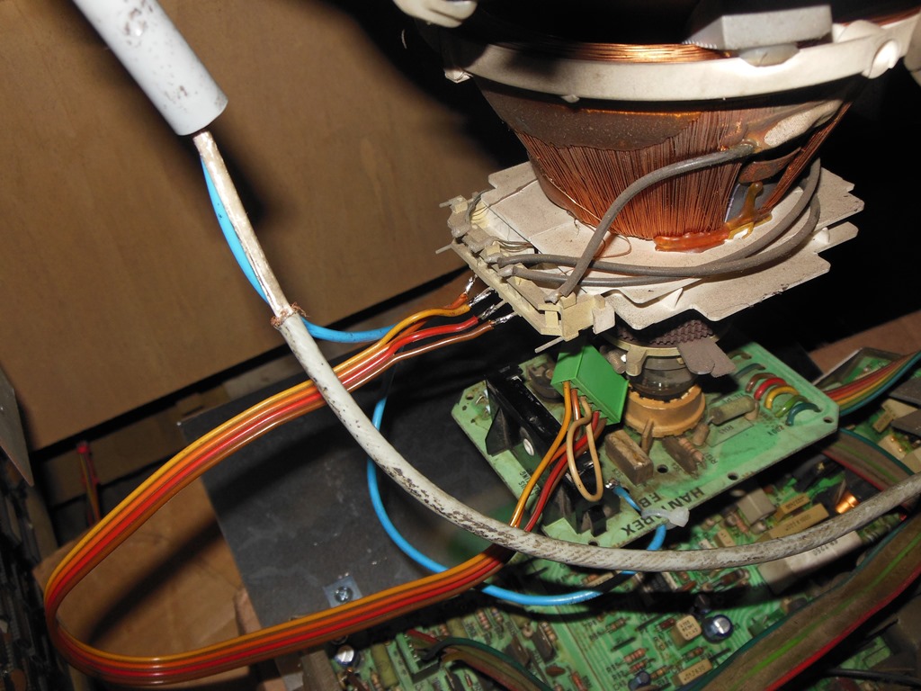
I assembled the diode arrangement on a small piece of prototyping board.
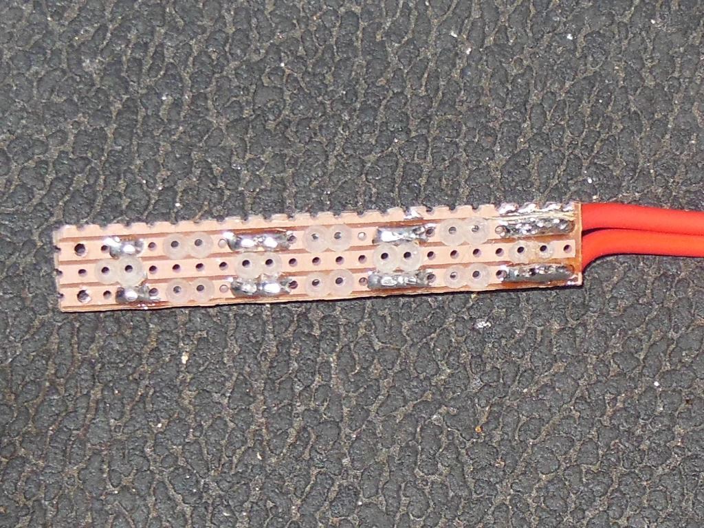
The adaptor board was then attached to the power cable assembly.
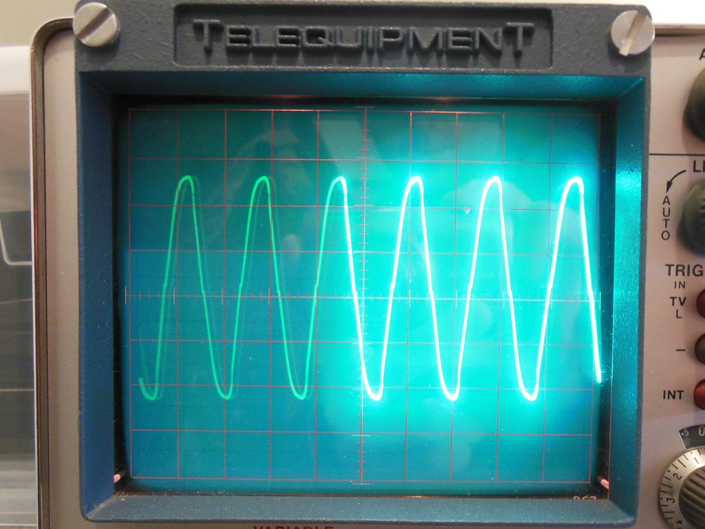
Since adapting the AC supply this way was unusual I setup a test to validate it using a 40W light bulb.
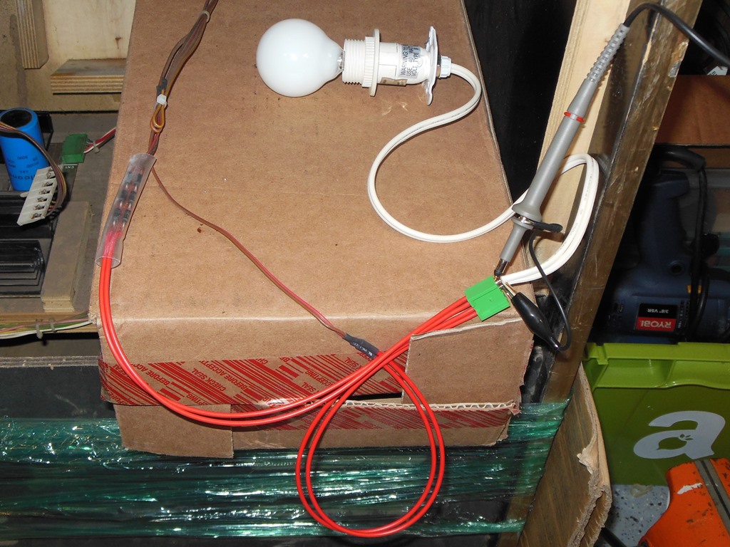
The voltage measurement looked OK and I also validated the waveform since the diode arrangement causes a zero crossing gap
in the AC wave as a result of the loss of the first 13V. This zero crossing "glitch" was visible on the scope but it didn't
look significant and the MTC-900 power supply is full-wave rectified anyway and thus it shouldn't matter.
Replacing the MTC-90 yoke cable with an MTC-900 cable completed the wiring portion of the conversion.
Full Testing
With all the mechanicals and wiring adaption done it was time to fit the chassis into the cabinet. The fit was good, looked
good and like it's native frame allows all the picture adjustments to be accessible.
Power on yielded no initial problems and a great picture!
Thermal Improvement of the 13VAC Adaptor
The game ran fine for few hours without any visible problems but inspecting the 13VAC power adaptor showed that it was hot
enough to shrink the protective heat shrink tubing around it :(
Clearly I must have underestimated the power dissipation of the 13VAC assembly. Examining the datasheet for the 1N5333 showed
that the 5W power rating is based on specific mounting characteristics and is derated based on ambient & lead temperature.
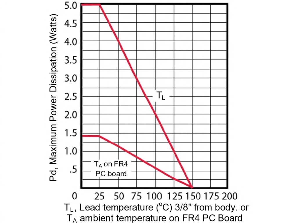
The graph in the datasheet by itself wasn't too helpful, however a search on the web suggested that the 1N4001 datasheet had
better information on mounting & thermal characteristics.
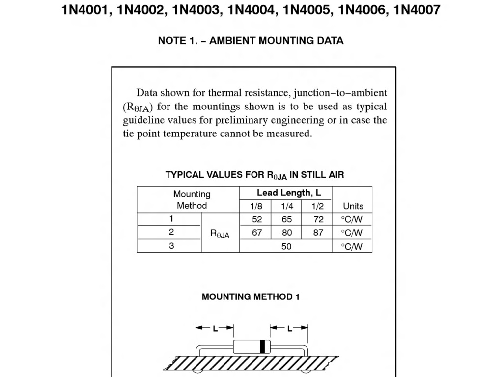
The key points were that the device uses the two pins as the heat sink and that they should be as short as possible and connect
to as much copper as possible on the PCB for maximum heat dissipation.
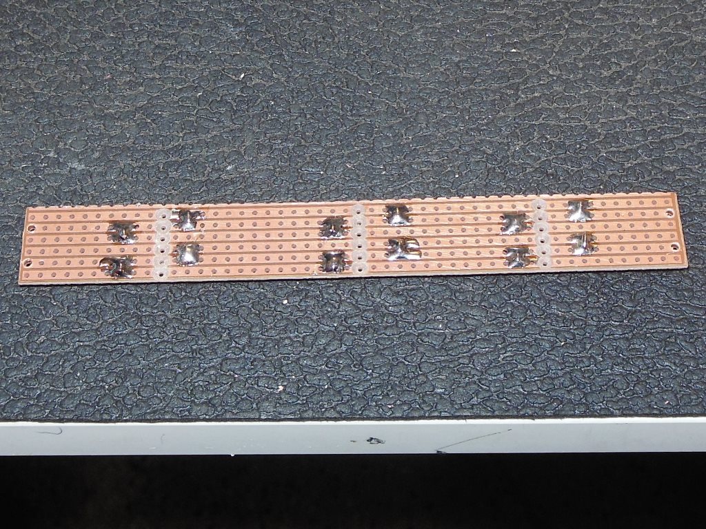
Therefore, I revised the mounting of the diodes onto a larger prototyping board.
The track cuts were made with a 1/8" drill bit, the diode holes widened with a 3/64" drill bit and the four cable holes widened
with a 1/16" drill bit.
On the tracking side each pin connected to two tracks to use all of the copper surface area as a heat sink.
Back in the cabinet the chassis again ran fine for a few hours and this time the 13VAC adaptor didn't become blisteringly
hot.
The final step was order some small wood screws and use them with plastic PCB spacers to attach the 13VAC adaptor to the
cabinet.
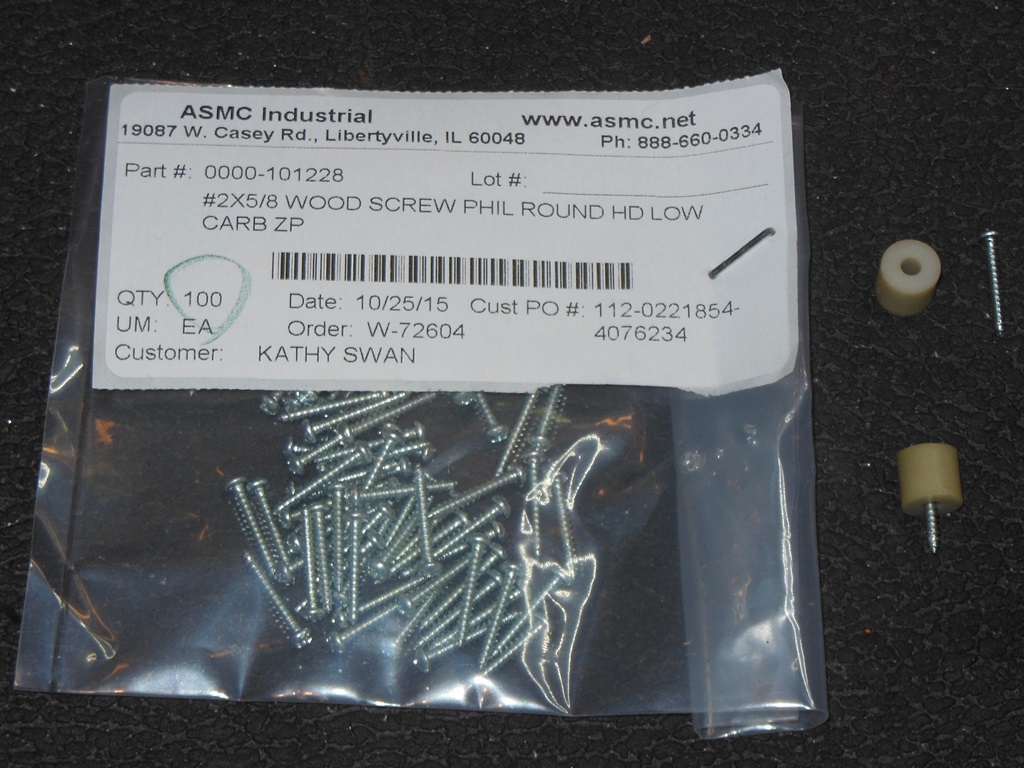
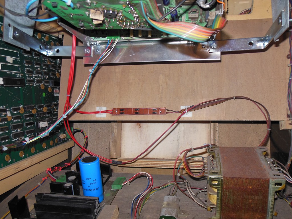
The natural place to mount the 13VAC adaptor into the cabinet was on the back panel under the monitor base plate where it would
be safely out of the way and away from other components in the cabinet.
The conversion has been run for many hours over many days an aside from fixing a bad transistor in the sync circuit on the MTC-900
there's been no further issues with it - it's already had more hours on it than I was able to achieve with the MTC-90.