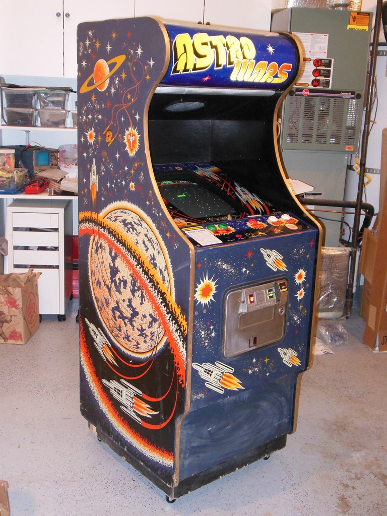
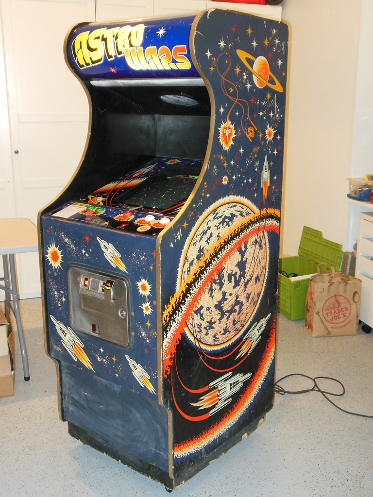
Can't quite remember how I got this game but it is a UK game and isn't one of the Duke of Lancaster games. This one is in better condition than both of the DoL games so I decided to restore this one.
|
|
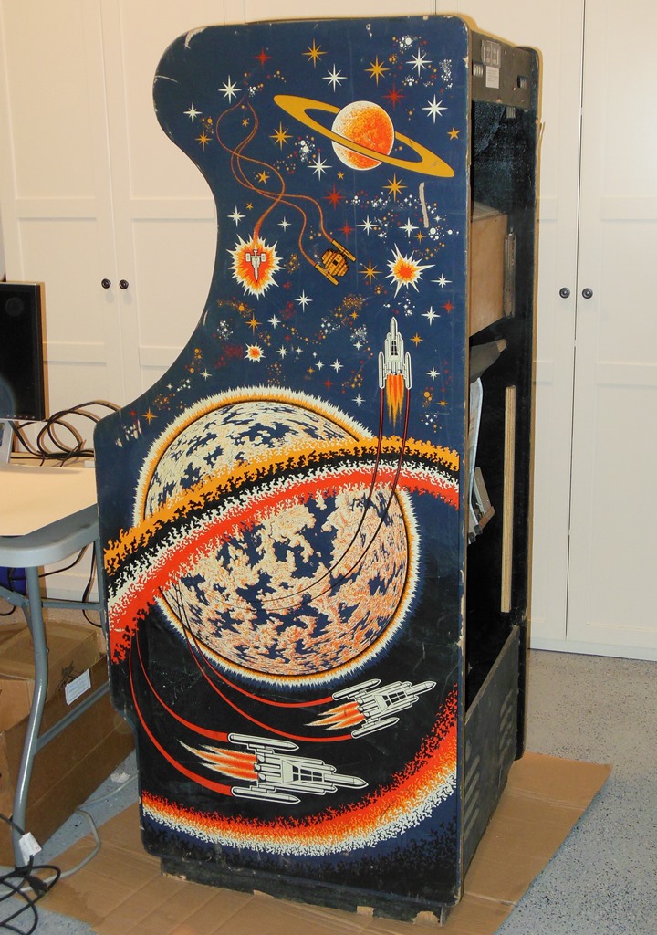
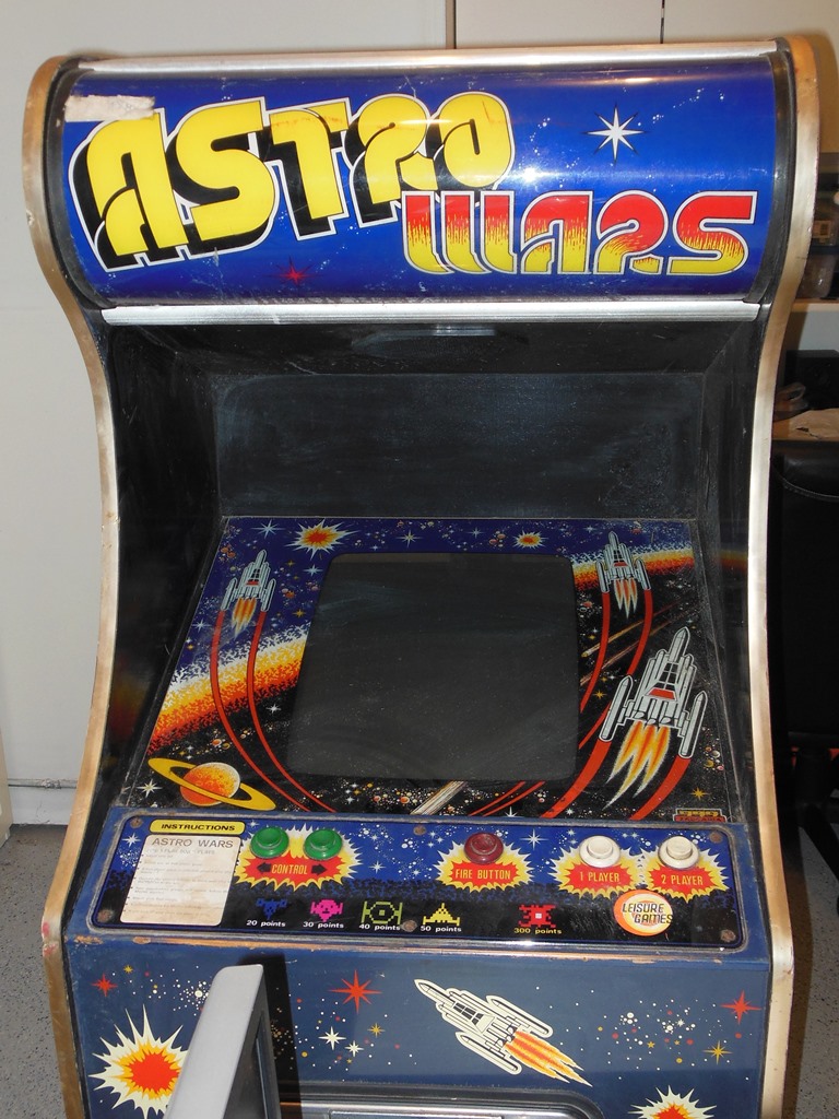
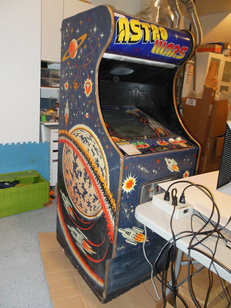
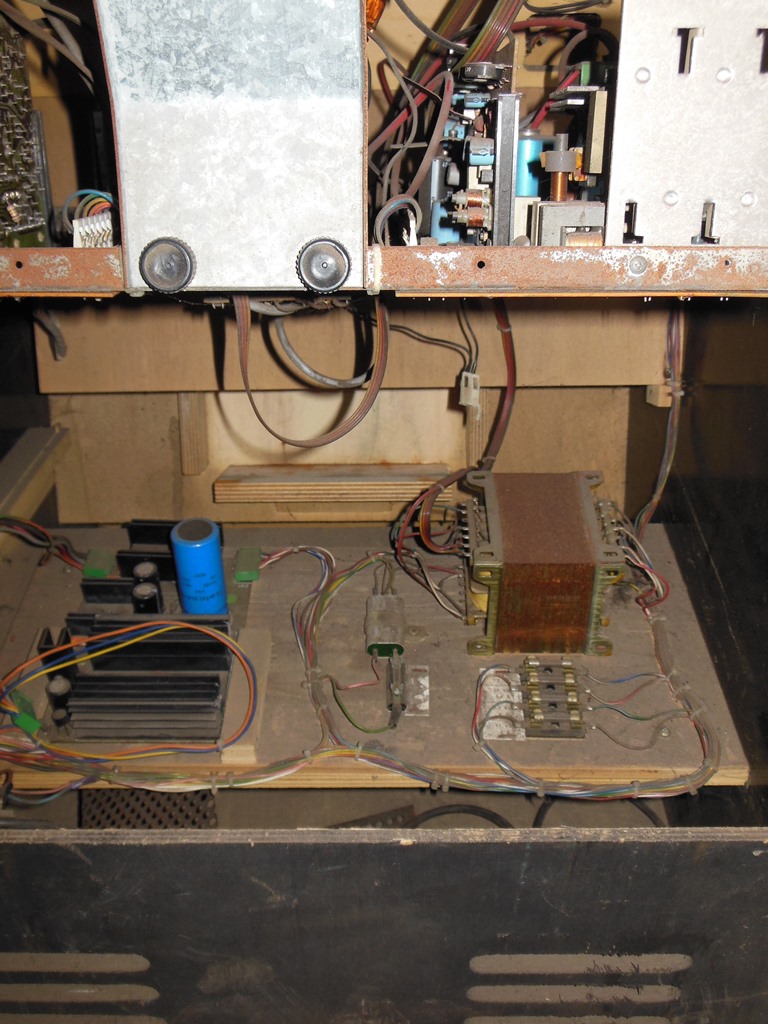
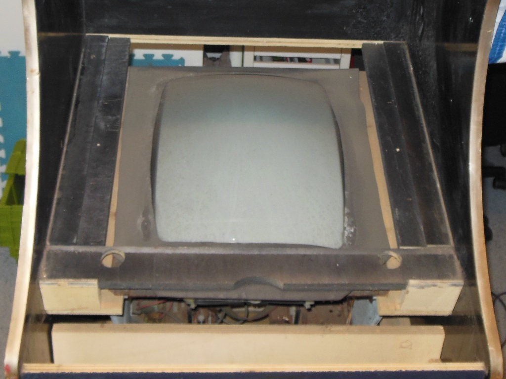
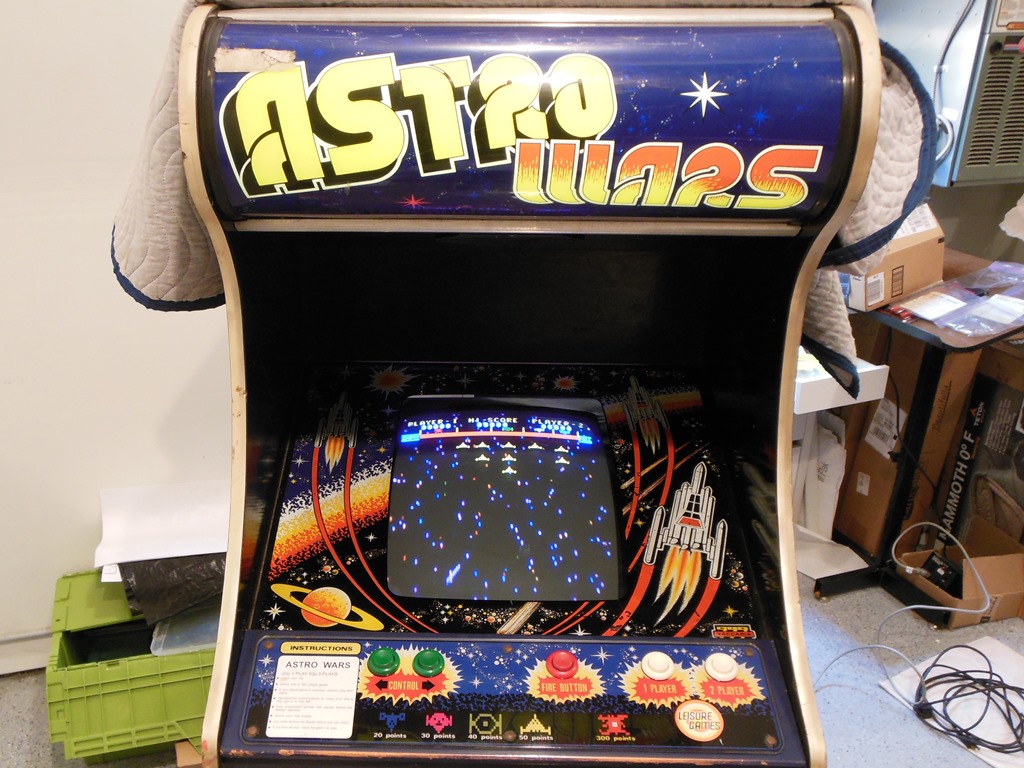
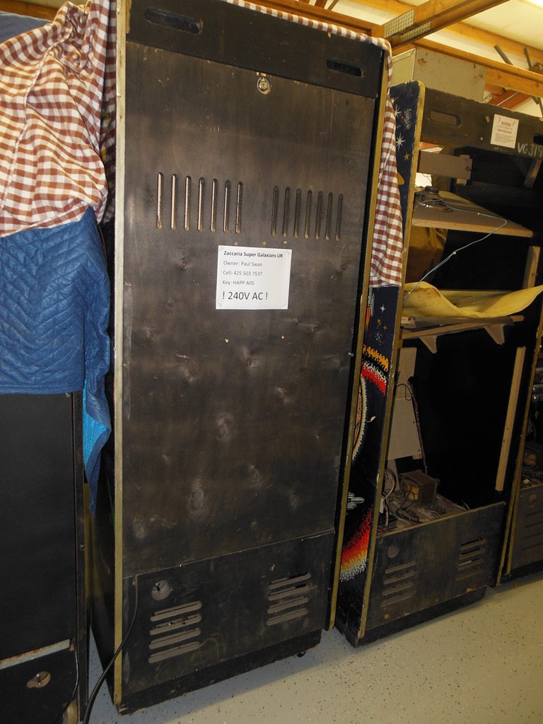
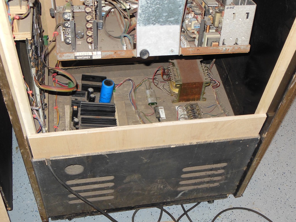
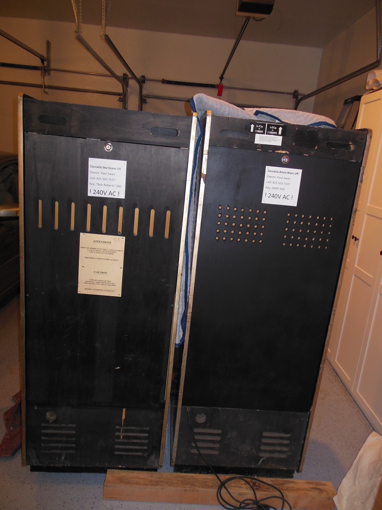
Exterior looks pretty good. The feet are missing and I'll castor it later. No obvious holes or missing artwork or trim. The back door is missing so I'll need to make one of those (neither of the DoL machines had back doors). The monitor & power supply are present and complete but the main game board is missing. The sound board is present.

|
The wiring looks complete and uncut. The monitor appears to be in good physical condition with all the daughter cards present. Doesn't look too bad electrically.
|
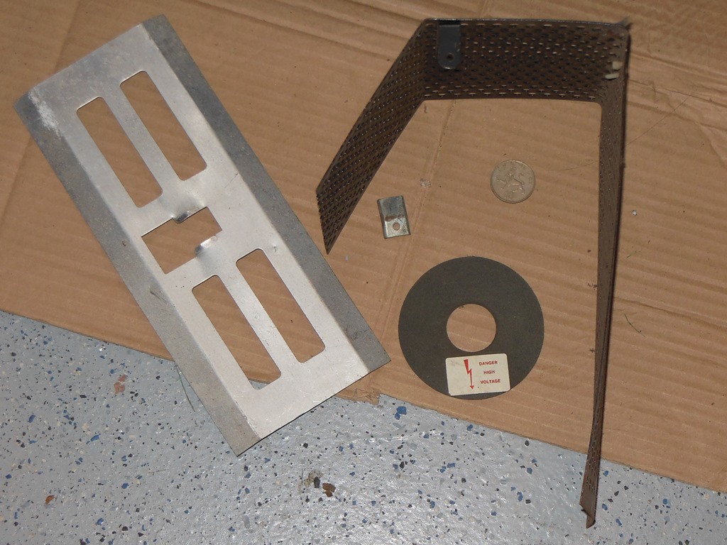
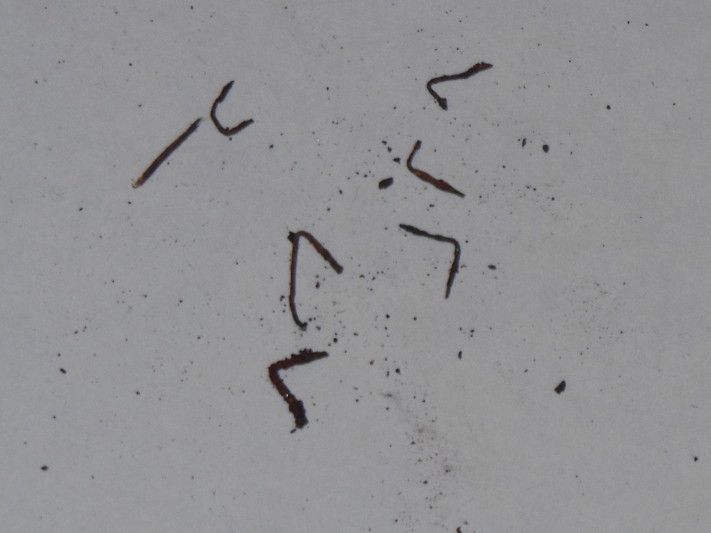
Found a collection of random metal junk in the bottom that doesn't appear to be from this game.
|
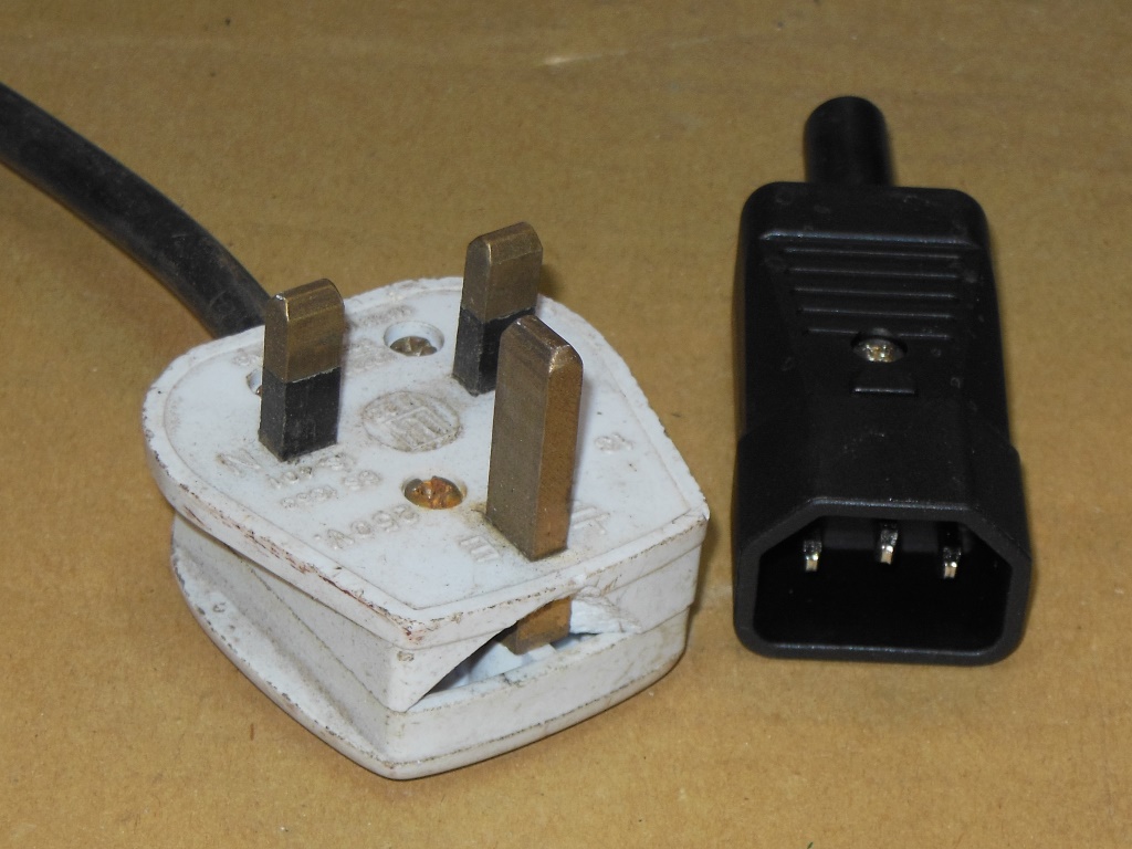
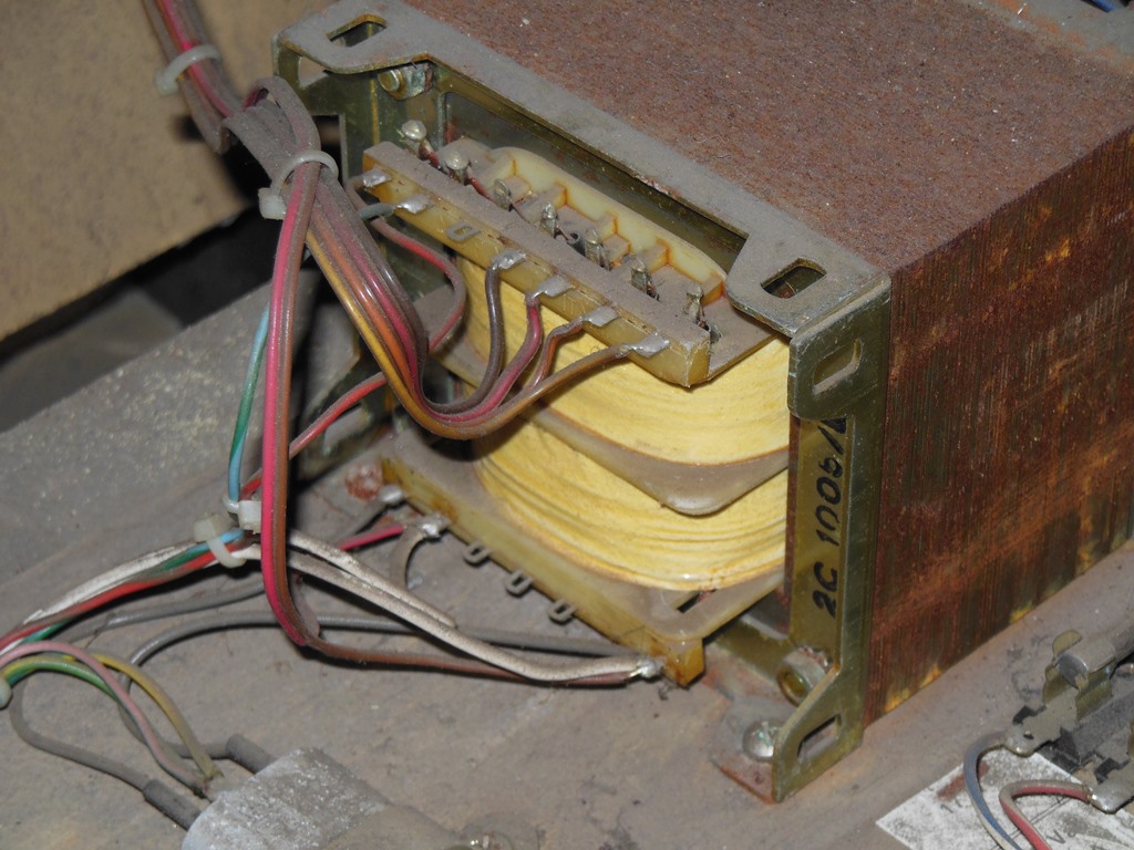
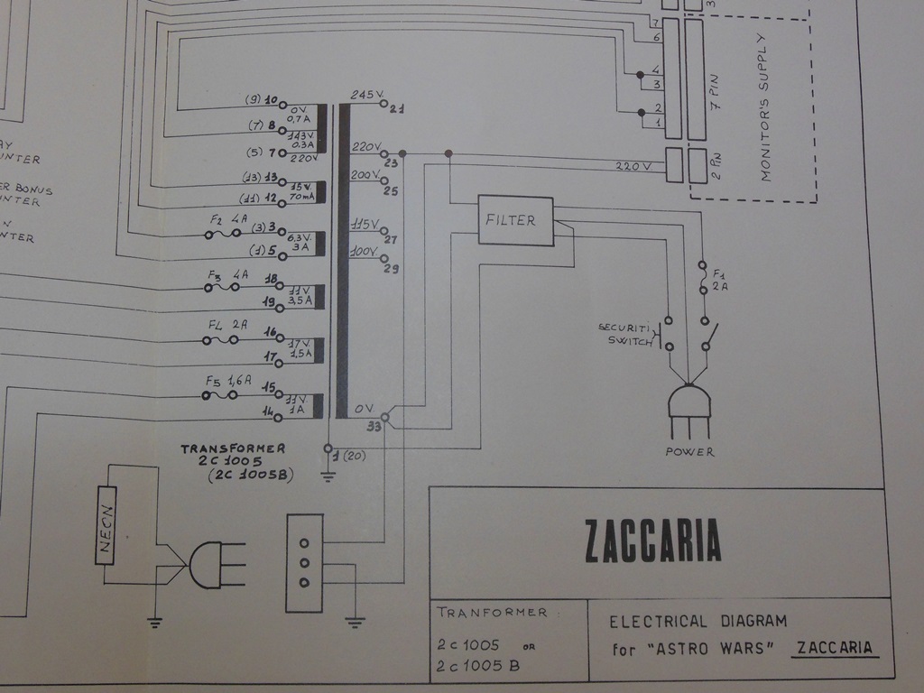
Since this machine was from the UK it was already strapped for 245VAC and confirmed that my prior conversions of European 220VAC games was correct :) The input is the only tap that's moved with the marque light and degauss remaining on the 220VAC tap.
|
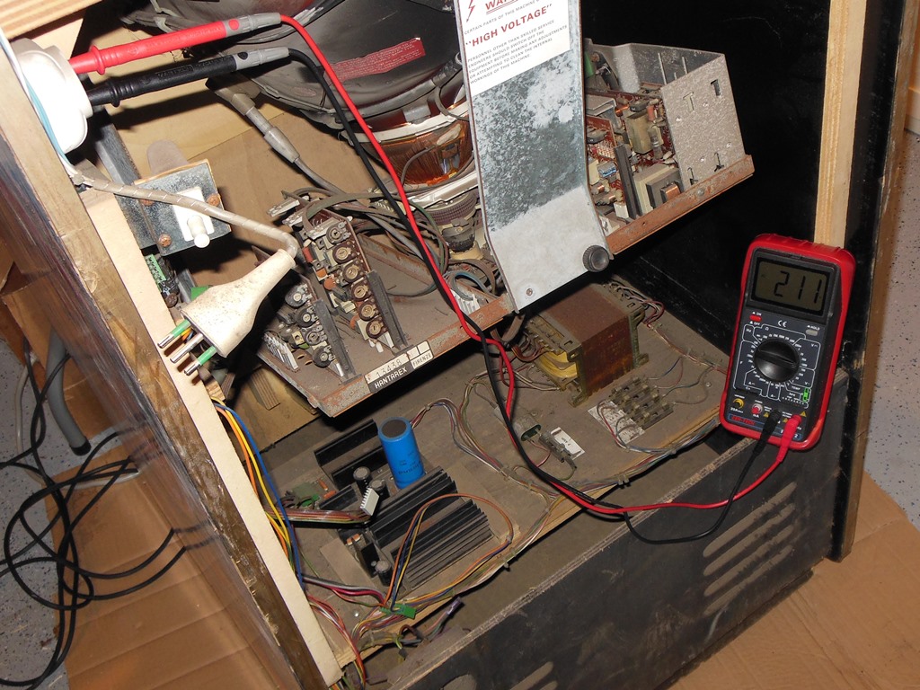
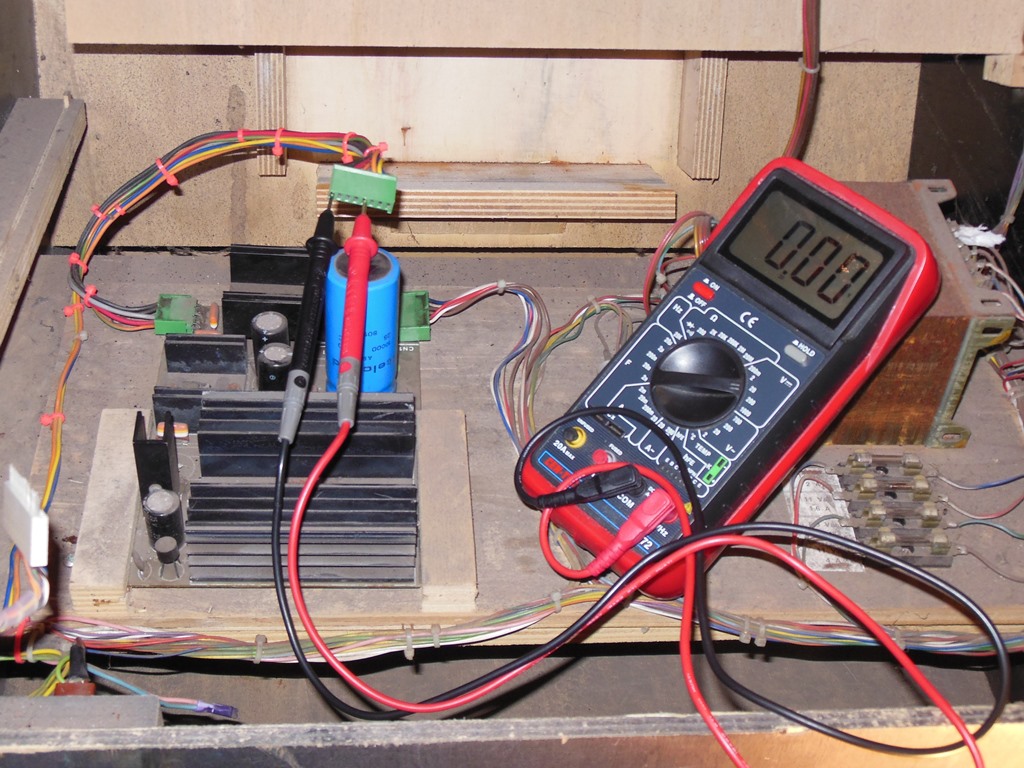
On power on the 220VAC at the marque light socket was 211VAC and thus OK. Neither marque light or monitor started. The game board power came out as:
|
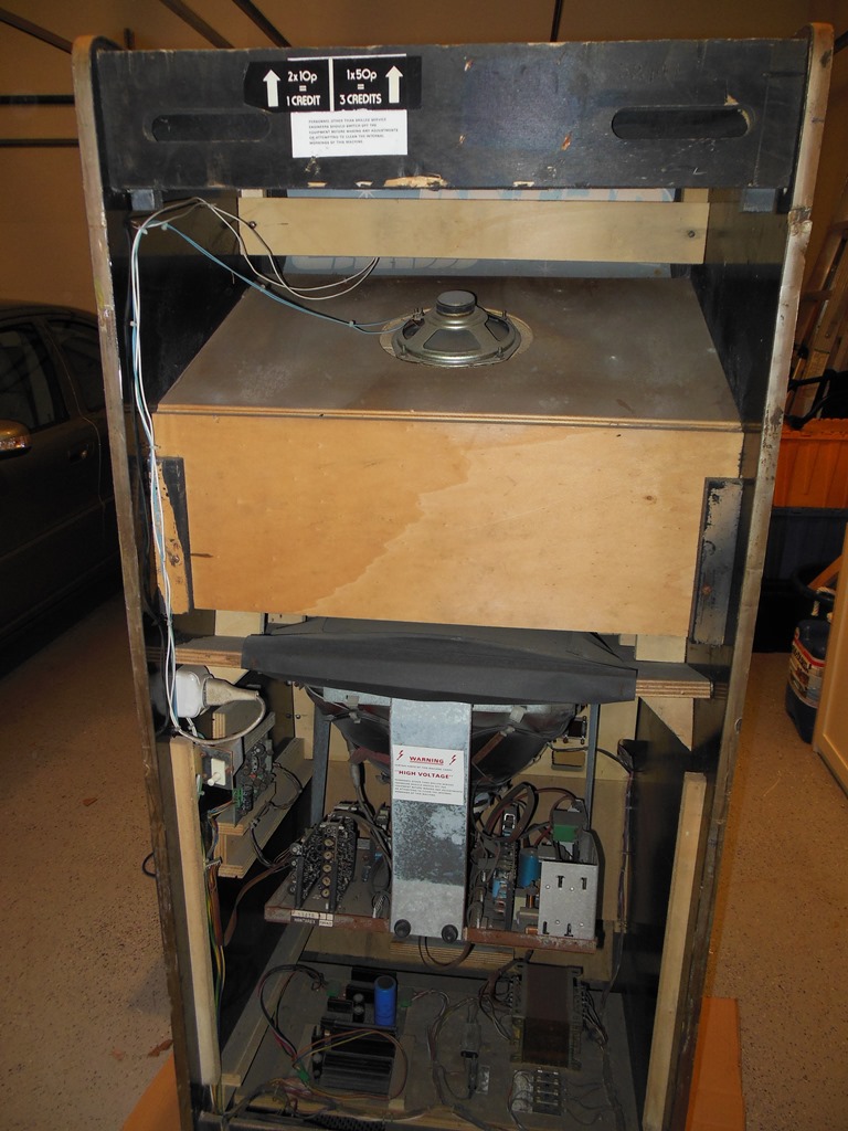
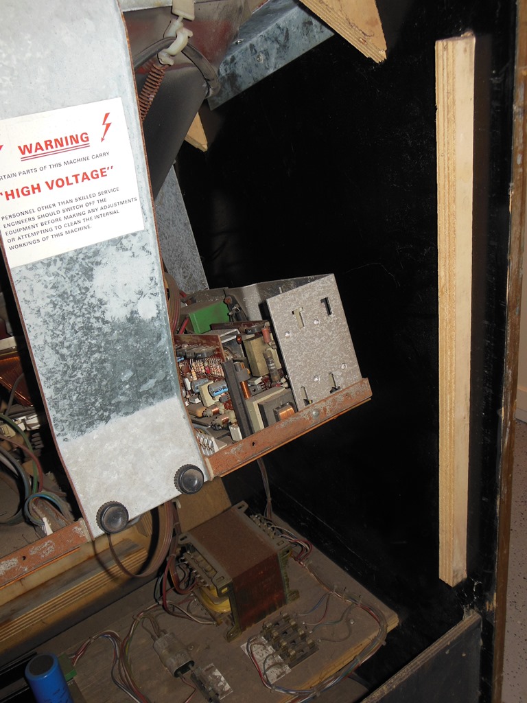
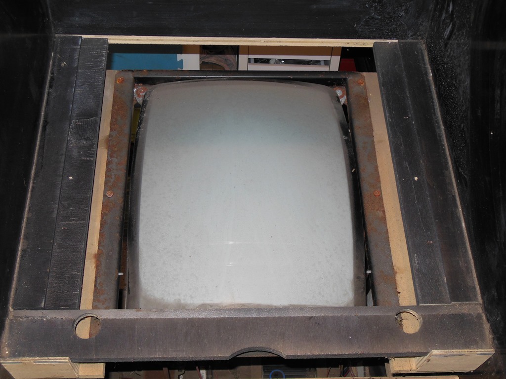
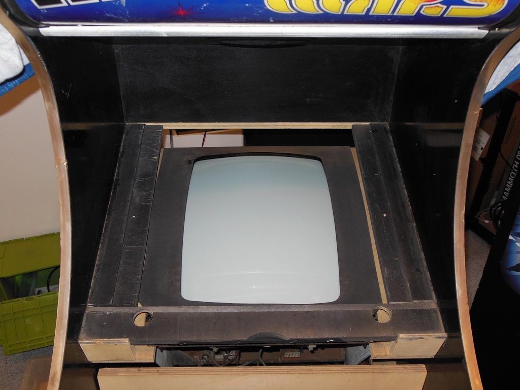
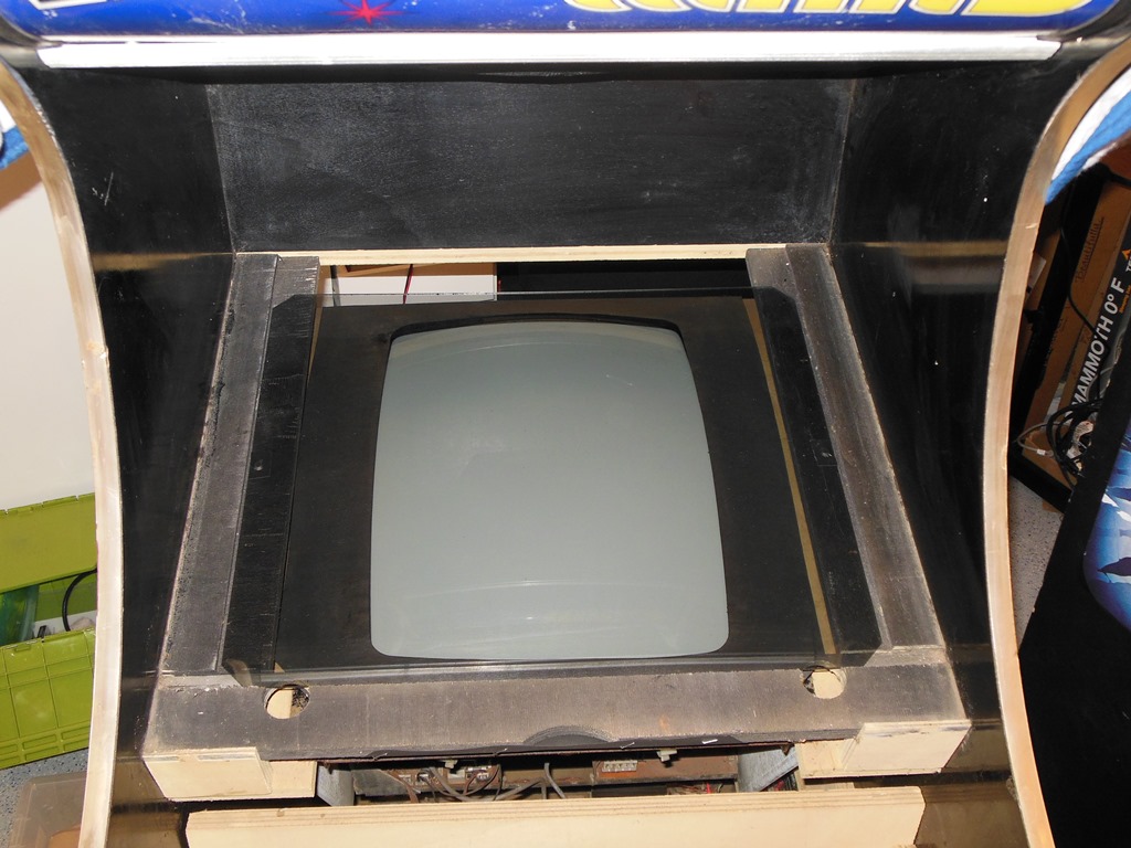
In order to work on the monitor necessitated being able to slide it back for better access to the chassis. To remove the monitor the glass bezel, perspex tint sheet and cardboard monitor surround need to be removed to be able to access the mounting screws. The cardboard surround was moldy and crumbling in places (a future work item) and the staples almost entirely rust dust.

|
This model of monitor has a bunch of LED's on all the internal voltage supplies making it relatively easy to spot missing voltages:
|
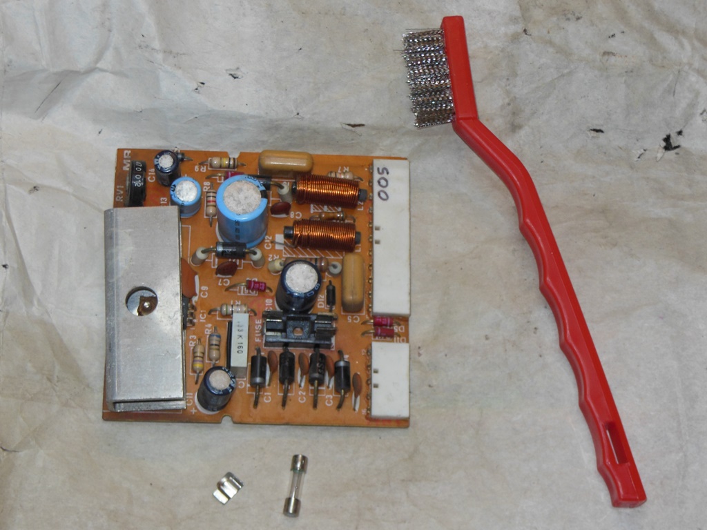
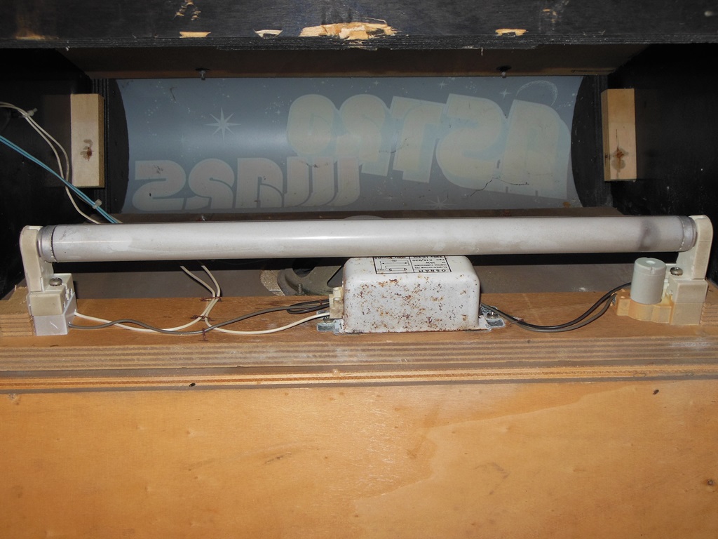
Removing the MR board and metering found an open circuit between fuse and fuse holder. On cleaning, the fuse holder fell apart and needed to be replaced. With the 16.5VDC supply restored the monitor still didn't start (no HV) however there was a burst of HV generation on power off for a fraction of a second.
|
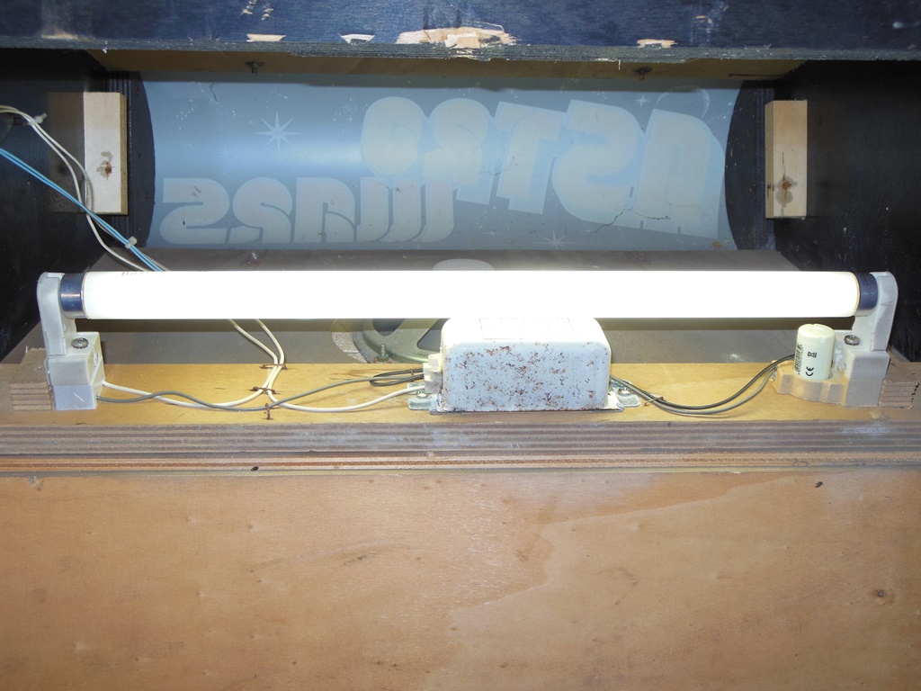
A new tube and starter brought the marque light back to life.

|
From prior repair work experience on this model of monitor, I tried replacing the ME board that provides the main oscillator for the HV drive transistor. Sure enough the monitor HV started with all voltages present. Replacing the TDA2591 with a compatible TDA2593 similarly fixed the original ME board, confirming a bad IC.
|
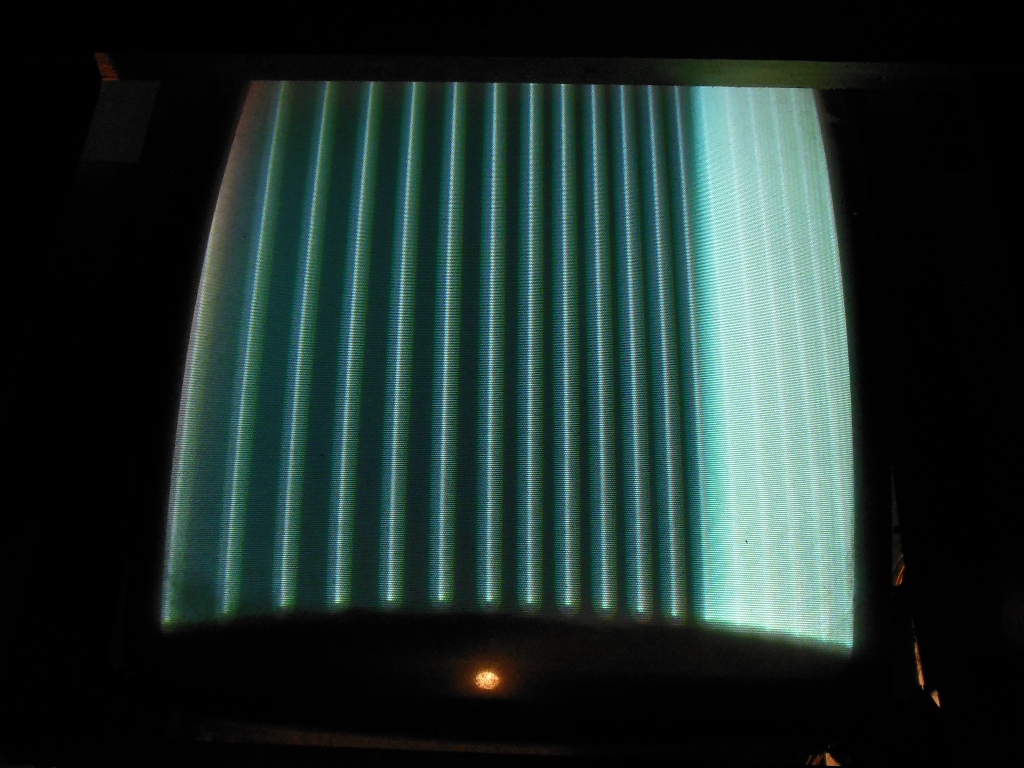
There was still more to do - the no-signal picture was mostly white and uneven with visible raster lines. The next step was to sort out a working board to provide a signal for the monitor.

|
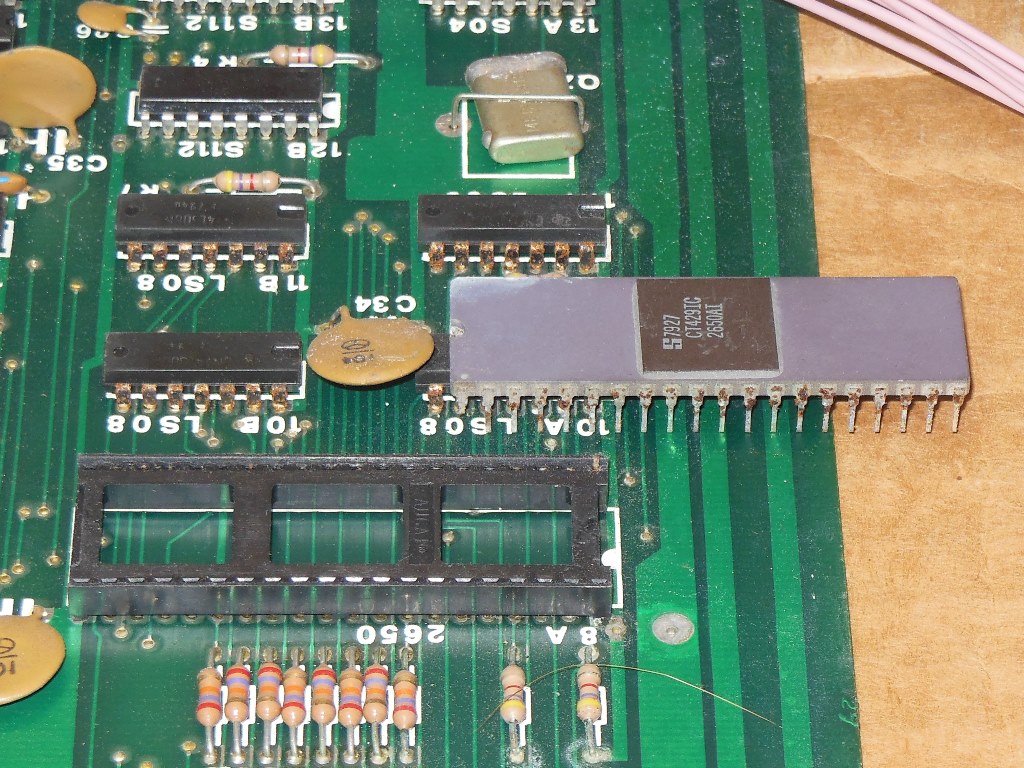
The game PCB was missing from this cabinet so I recovered a game PCB from one of the Duke of Lancaster cabinets. On the bench the game didn't boot. This board had been open to the sea weather for 25 years and thus though clean the IC pins were badly corroded. Removing the 2650 CPU left pins behind. It was clear the 2621 & 2650 IC pins were too far gone to be salvageable as were both their sockets :(


|


|
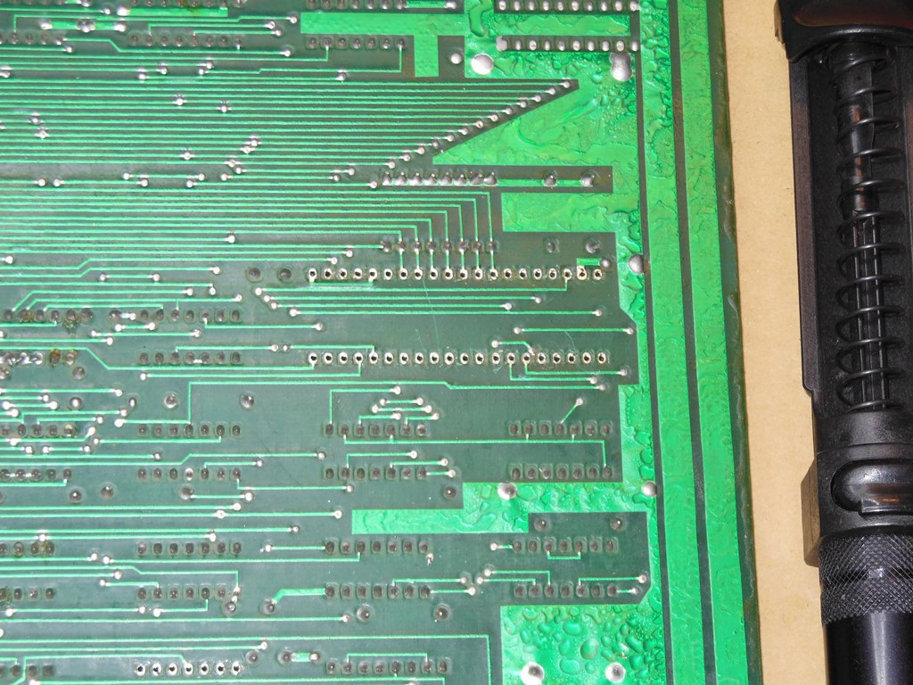
The pictures illustrate my preffered way to remove IC sockets with the least amount of damage to the PCB:
|
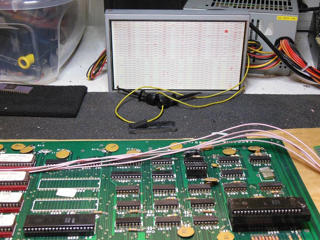
Alas, even with replacement 2621 & 2650 in new sockets there was no change. Time to see what the in-circuit tester found...
It didn't get very far - the data bus is supposed to be pulled high when idle but D4 was seemingly random. This randomness was present through all ROM & RAM operations in addition to being there on idle bus. Looking on the scope showed D4 had a signal on it and I suspected a short. Grounding D4 caused the graphics to change so it looked like D4 was short to one of the graphics signals. Clipping one side of a multi-meter onto D4 and using the other side to go down the pins of every other IC on the board found a hit on the missile RAM. D4 was short to OM1 on the 2101 RAM at 3F. I didn't see any visual short on the board and began looking at the schematics for a common factor. OM1 is on pin 4 of the LS244 at 5E and D4 is on pin 3 of the same. Cutting pin 3 at the LS244 cleared the short and the meter confirmed that pin 3 & 4 were shorted inside the IC.
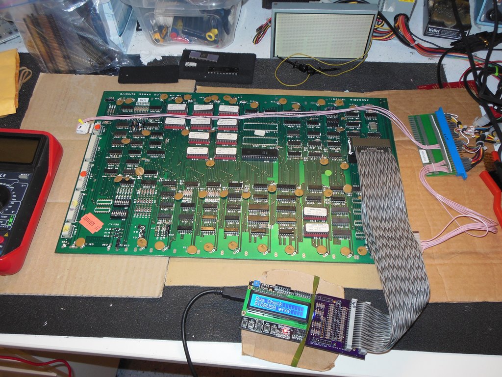
The next problem to solve was that all the ROMS failed to read properly. Some had bad values, inconsistent CRC or were all FF. This was again due to pin corrosion with four program EPROMS having one or more rusted-through pins. Programming replacements fixed those and also allowed the remaining EPROMS to read properly. Thankfully all the EPROM sockets appeared to still be OK and all ROM checks passed now.
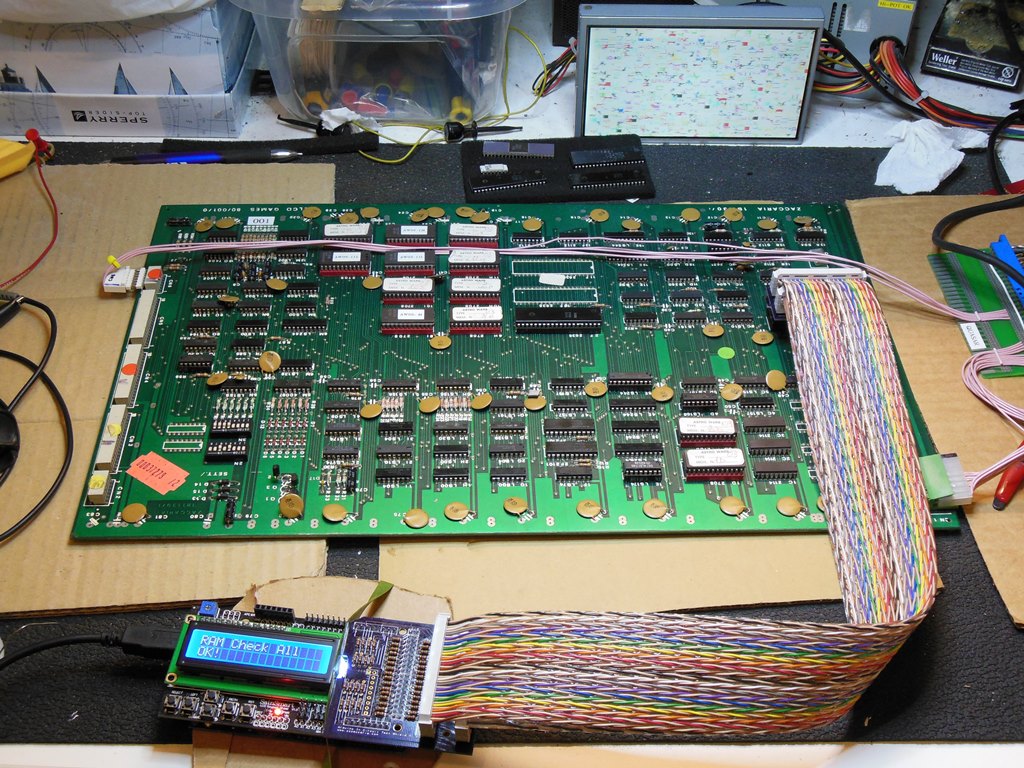
The RAM check passed all the RAM except the work RAM in the 2636 that was failing both with data errors and an intermittent bus hang (no OPACK). This changed when the IC was pressed on. The IC pins looked OK but the socket pins seemed to be bad. A new socket fixed all the 2636 issues. With all RAM and ROM checks passed it was time to try a CPU.
The game booted up and seemed to run reliably but there were still some graphics problems to solve. The first was jail bars through the characters. On the scope the eight graphics bits looked OK out of the EPROMS and into the shifter at 4D. A pulse injector on the EPROM data bus showed no visual effect on pin 9. Suspecting the LS166 at 4D as having a bad input and running the game with the graphics EPROMS removed still yielded jail bars and no effect from pin 9. Changing 4D fixed the jail bars.
The next graphics problem was the lack of a star field. This problem traced through to no Q output from the LS74 at 6O. A piggyback check had no effect but cutting the Q output and then piggybacking brought the stars back. Thus, changing the LS74 at 6O brought the stars back.
The game was running fine now but with one intermittent issue remaining. After being on a while all colour would disappear leaving all the characters a single colour. I suspected the colour latch LS174 at 1E. Probing with a scope caught the colour outputs fading away to a single value but both colour inputs and clock (LOAD) looked fine. Changing the LS174 at 1E fixed the colour problems.

|
All tests passed and finally one game PCB was up and running. Now I could continue to work on the monitor.
|
|
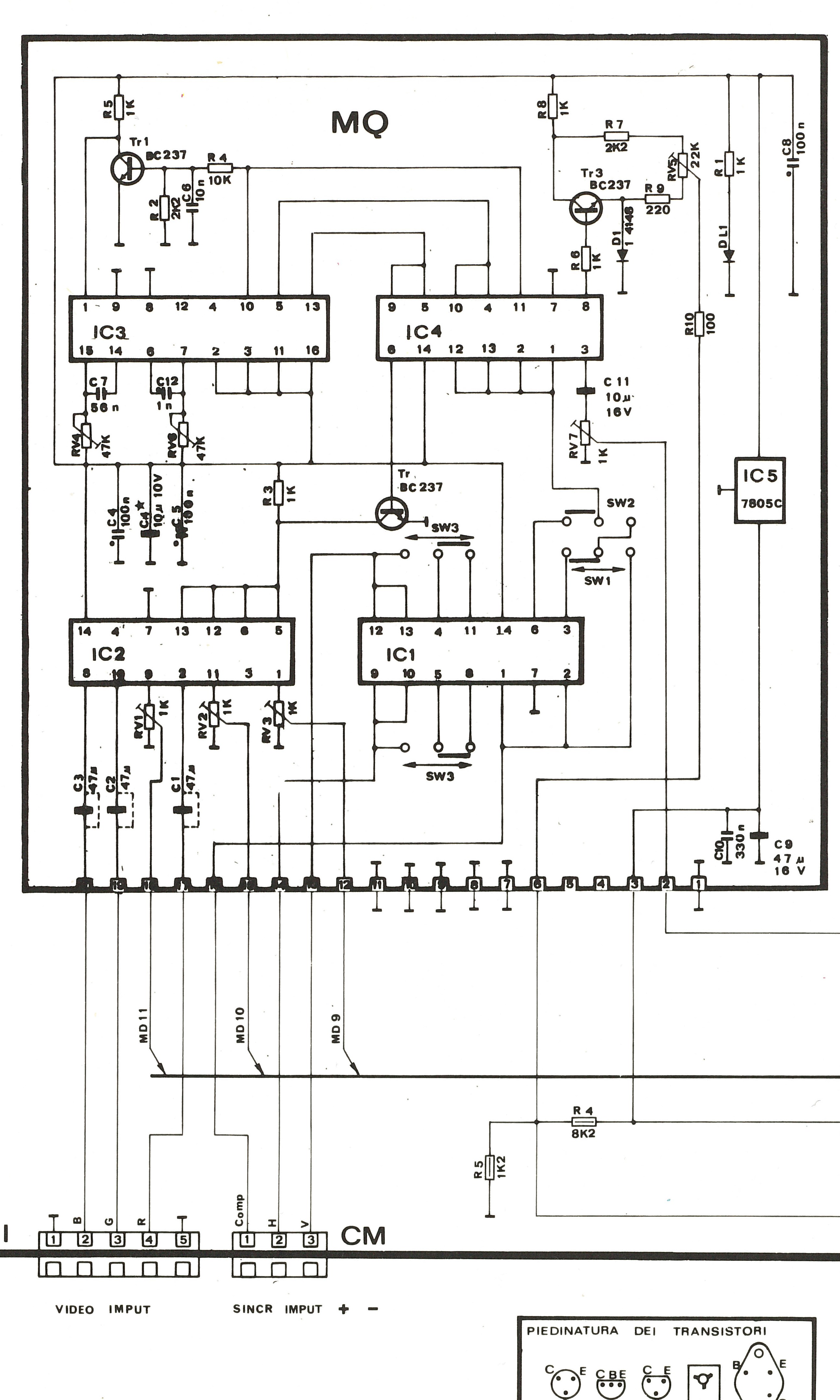
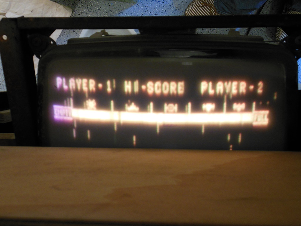
Installing the game board yielded absolutely no change from the no signal picture - mostly white and uneven with visible raster lines :( Swapping out the RGB drive board MD with a spare partly working one gave no picture at all with the brightness control on the MQ board having no effect. Moving the game up to the bench to be able to use the oscilloscope to fault find was the next step. The scope showed that there was no colour drive output on MQ pins 9/10/11. The sync input on MQ looked OK however there was no blanking output on MQ pin 6. MQ IC4 looked like it was working but there was no ouput from IC3. The scope showed IC3 pins 1 & 10 had signal inputs but the rest of the IC was idle.

|
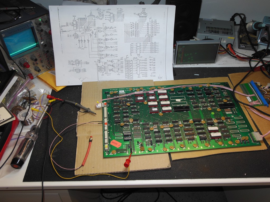
The schematic for the MQ board in the Hantarex MTC-90 manual is appallingly bad since nowhere in the manual does it list what the IC's are and the lack of any function annotation means it's not possible to determine what the circuit is actually doing. It was the second time I'd been faced with an MQ fault and useless schematics so it was time to scan in the schematic and improve it to be useful by adding the part codes, pin annotations and strap configuration used for these games.

|
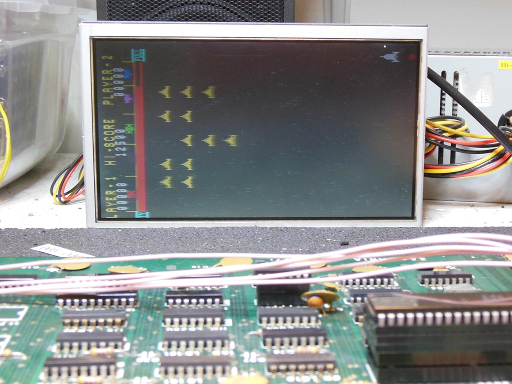
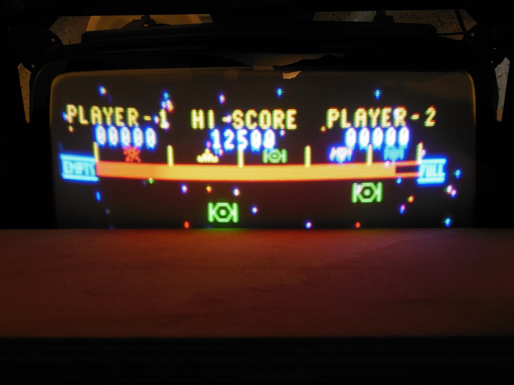
With the updated schematic in one hand and an oscilloscope in the other it looked like the 74C221 monostable was bad. Replacing it brought up a picture, the same poor picture I'd had before using the spare MD board. Switching that out with the original MD board yielded a black screen again. Curious to see if the TDA2530 was the problem with the poor picture on the spare MD I swapped them over and discovered that the TDA2530 on the spare MD was in fact good and the original MD TDA2530 was bad. With the original MD and a spare TDA2530 the picture looked pretty good!

|
The colour balance was a little off (blue seemed a bit high) and there was a small amount of fold-over at the bottom. The photo (taken with flash) hides that the brightness is actually a little too high.


|
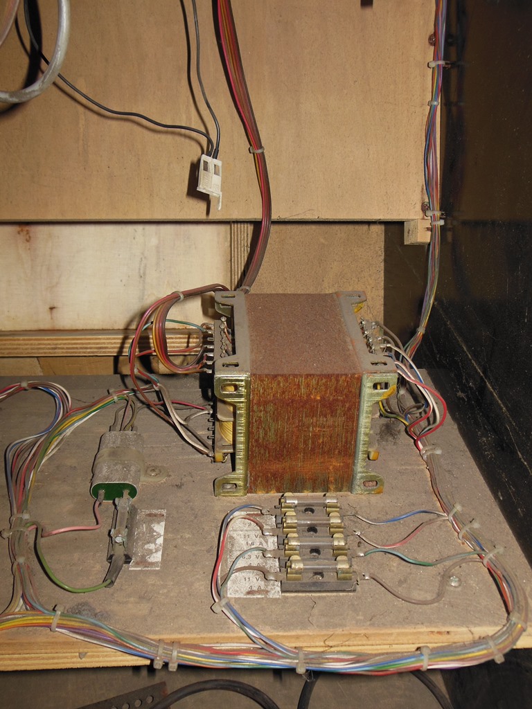
Power on a couple of days later and the game was no longer booting :( The game board itself ran fine on the bench so attention turned to the power supply. The +5V looked good but the +12V was missing. Using a meter to trace back showed there was no unregulated +14VDC from the power board so the problem was before the regulator. Tracing further back showed there was no 17VAC input on pins 1&2. However, 17VAC was present OK on the transformer taps. Metering through the wiring found that the 17VAC fuse was open with the fuse holder. The fuse was tight in the holder but there was no electrical contact between them. I used a Dremel with a small grinding head to remove the oxide layer from all the fuses and holders. The game was booting again. :)
|
The monitor surround was very dirty and had quite a bit of mold damage that had actually eaten away enough of the cardboard that it was paper thin with some tears and holes in places. It was a borderline decision to repair versus replace but I decided to start trying repair first. The dirt came off pretty well with a damp cloth (needing extra care on the thin areas) and the surround was set to flatten and dry for a few days.

|
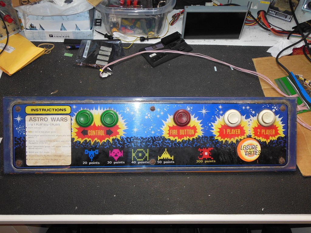
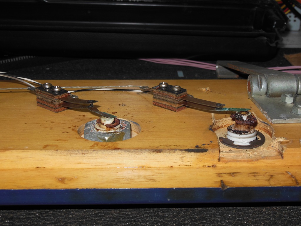
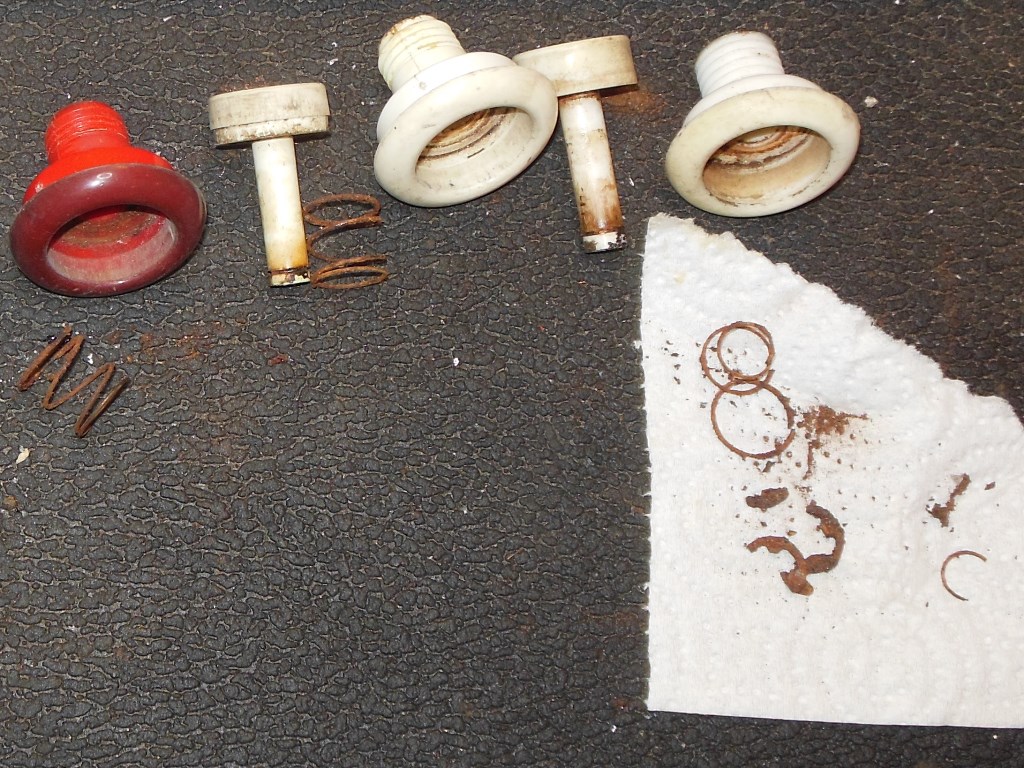
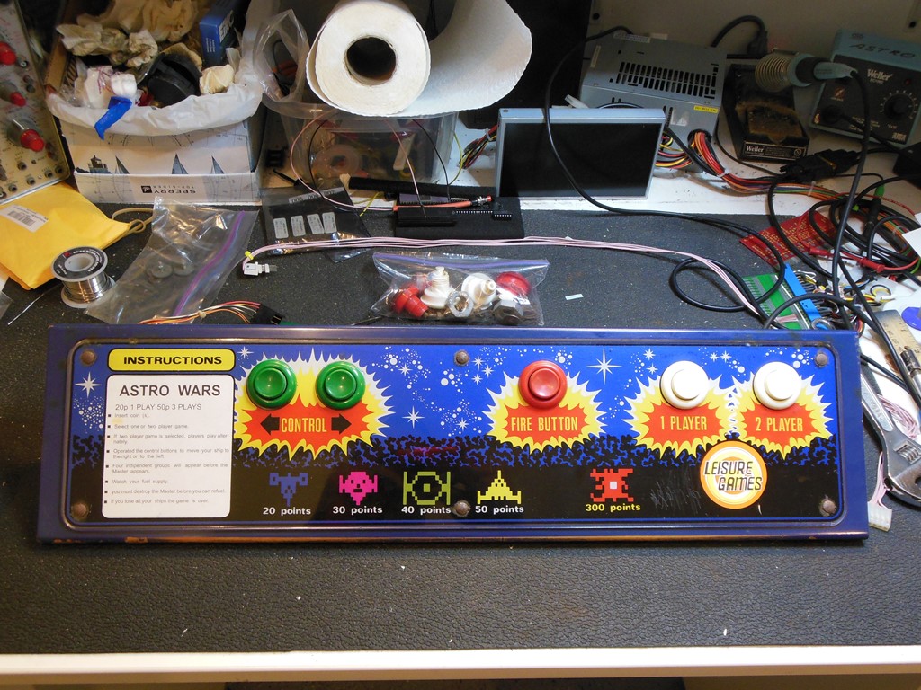
The control panel was dirty with water damage on the instruction card. All the overlay bolts were very rusty. Inside, there was a progression of rust ranging from severe on the player start buttons to just surface rust on the direction buttons. Likely the game had been stored for a long time with one side more water exposed than the other. One of the leaf switches was damaged and one button was missing it's nut that had been replaced by cutting away part of the woodwork to be able to fit a C-clip instead. One blown diode had been piggy-backed with a replacement.
|
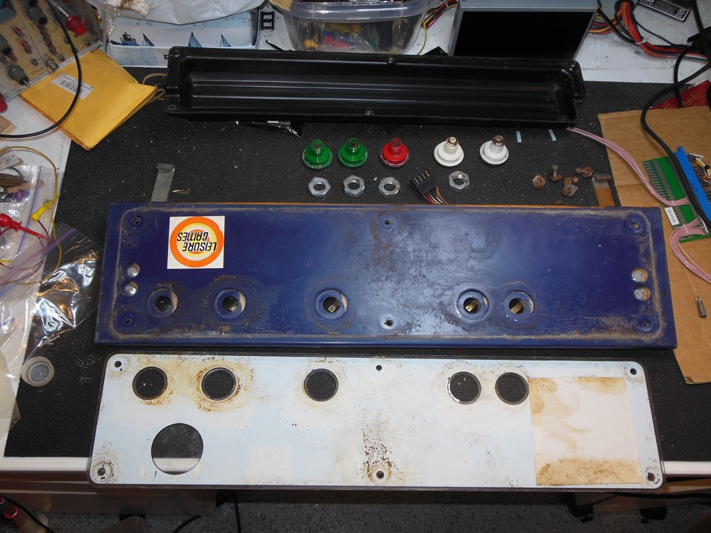
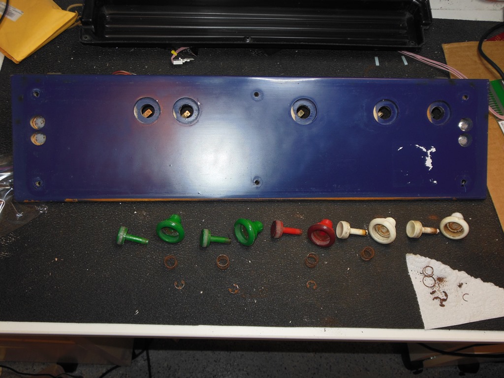
I removed all the overlay bolts and buttons to separate the overlay for cleaning. The paint on the panel cleaned up with a damp cloth. Disassembling the buttons revealed the same progressive rust - the springs were little more than dust in the player start buttons but salvageable on the direction buttons. I would need to find some replacement springs, C-clips and a nut to repair them.

|
The buttons I soaked in hot soapy water to loosen the nicotene and rust staining before running them through the dishwasher.

|
The game board and monitor were running fine now however the game would not coin up. Metering the coin micro-switch and it's diode showed they were both working. Metering the cabinet wiring also showed that the coin switch was working properly all the way to the game board connector so it was looking like it was board problem.
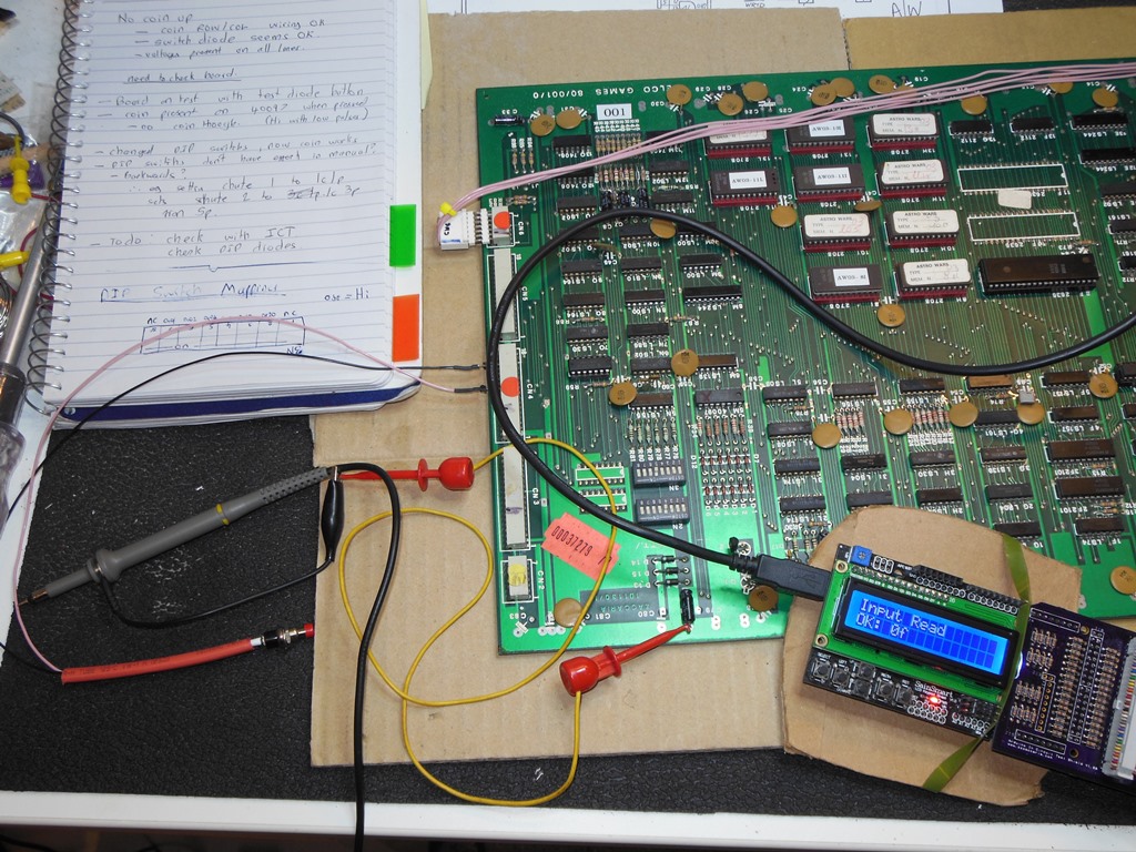
Since this game uses multiplexed row-column inputs I needed to make a test switch with an inline diode to be able to test the game inputs. On the bench the with the test button connected to the coin pairing had the same result - no coin up. I adjusted the DIP switches to 1 coin 1 play on both slots after which the coin inputs worked but gave the wrong number of credits. Something didn't feel quite right with the inputs - coin, control panel and DIP switches all share the same multiplexed design so I suspected a fault. To be able to test it properly needed the Arduino In Circuit Tester software updating to add support for reading inputs/DIPs and writing outputs first, however.
|
With the Arduino ICT updated to add input and output port maps it was clear that the
inputs were not working properly. The lower 4 bits of the port always returned 0x0F no matter
what the input though the upper 2 bits of the port were working.
The mapping of the DIP switches is as follows:-
| 8 | 7 | 6 | 5 | 4 | 3 | 2 | 1 |
| n/c | 0x01 | 0x02 | 0x04 | 0x08 | 0x10 | 0x20 | n/c |

|
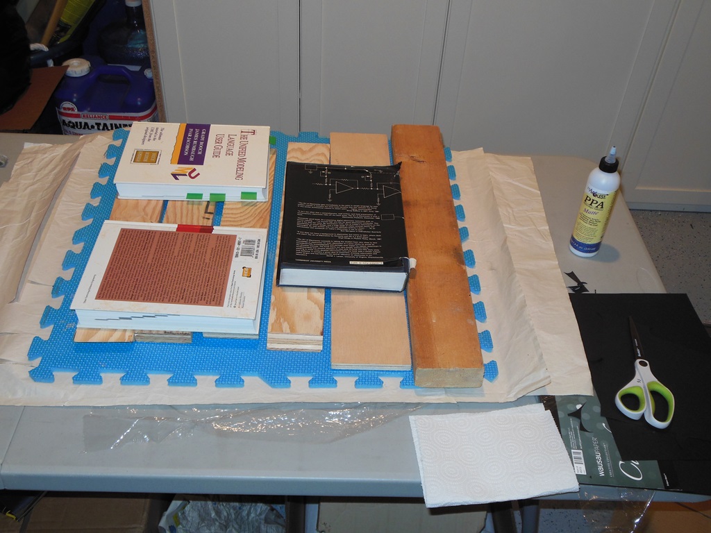
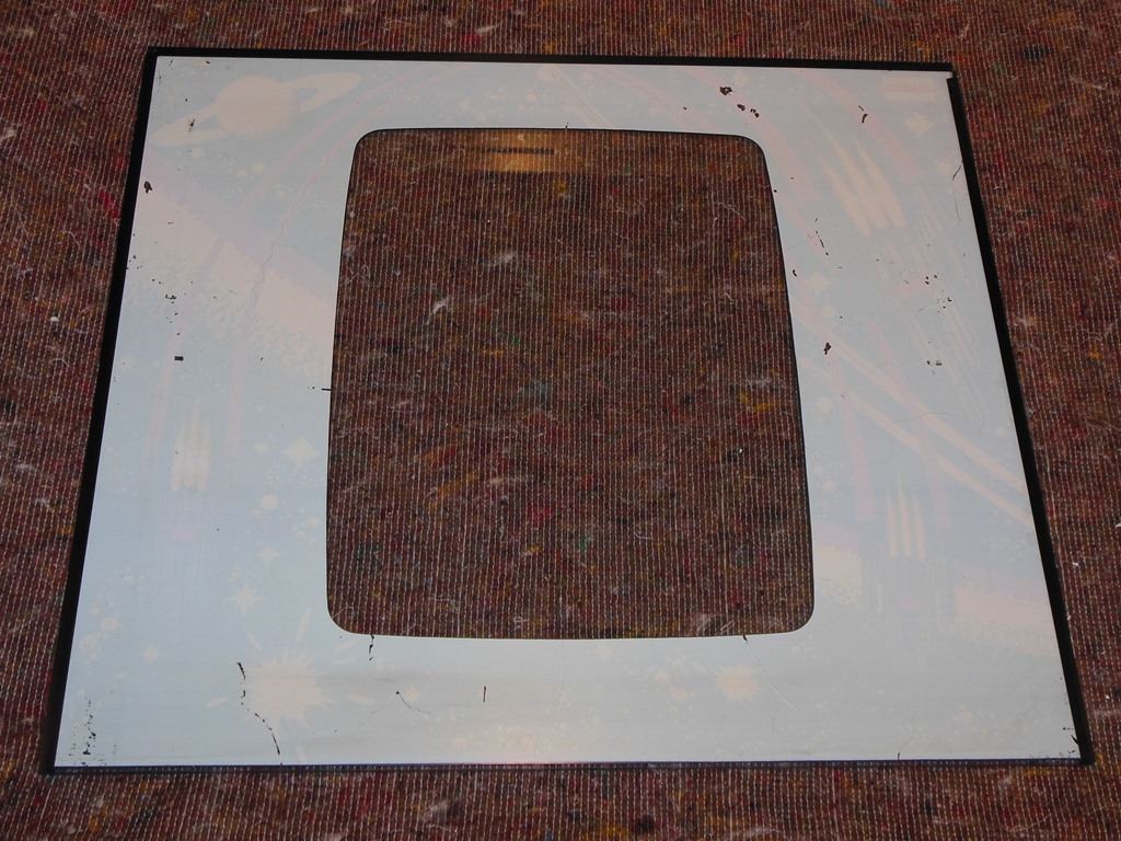
The monitor surround had a few mold damaged areas that in some places left holes in parts of the surround. After a pass of cleaning and flattening I cut out patches to repair the damaged areas, glued them and then set them to dry pressed flat. After drying the surround looked reasonable and whilst the holes can still be seen up close, under the smoked plexiglass they're not noticeable.
|
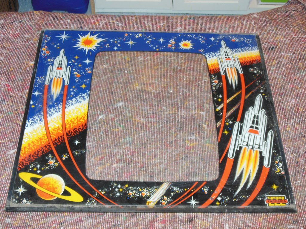
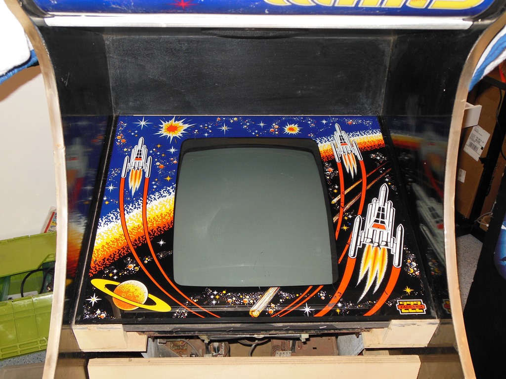
The monitor glass has some flaking, bubbling and holes in the artwork. Of the three monitor glasses I have this is the best glass out of the lot (the other two have either broken corners or worse artwork). There is repro artwork available for this game (by the Dragons Lair Fans forum folks) but this glass is not yet bad enough to need complete replacement.
|
No problems with reassembly - stapled the cardboard monitor surround back on, cleaned and attached the smoked plexiglass and refitted the monitor glass beading and the glass itself back into the cabinet.
|
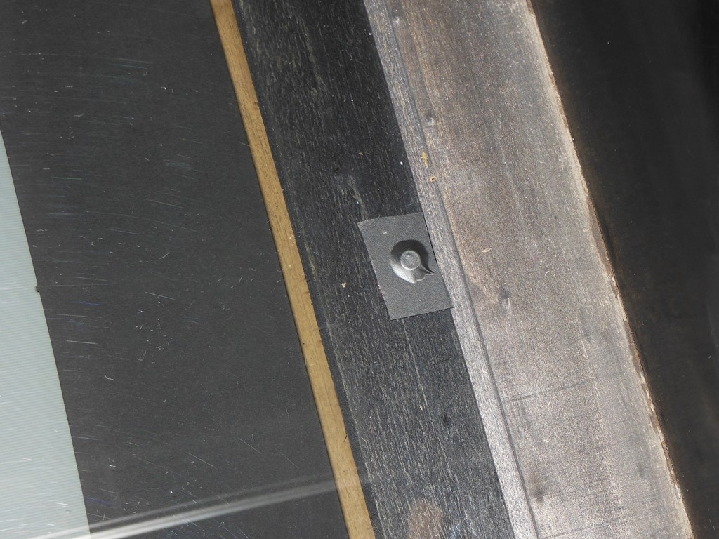
The smoked plexiglass has screw holes and the woodwork underneath has matching holes but the screws themselves were missing. Small replacement screws with a small piece of black tape over the top (to both protect the monitor glass artwork from scratches from the screw head and hide the screw) secured the smoked plexiglass in place.

|
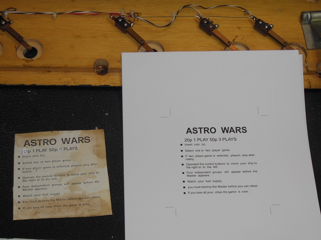
A friend from the Dragons Lair Fans made up artwork for the instruction sheet to replace the moldy water damaged one.
Two of the leaf switches were corroded and bent so I recovered a couple of good ones from the old hacked Sea Scare control panel. Astro Wars uses multiplexed inputs and has specific leaf switches with an extra tab to mount the diode across.
After refitting the control panel it was time to try the game again. Coin and start worked fine and the game played fine but there was no sound.
|
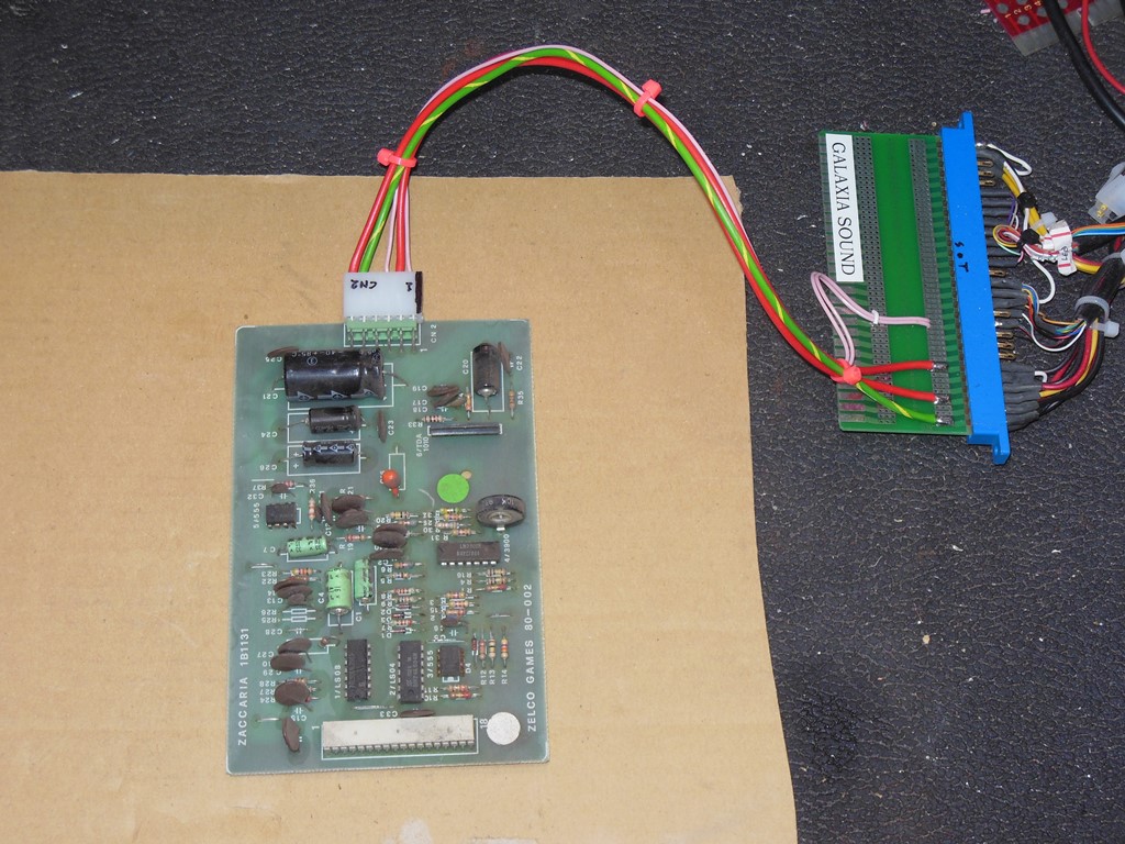
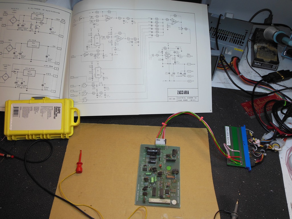
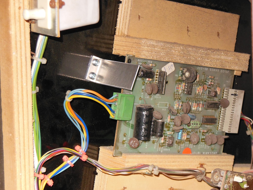
The Astro Wars sound PCB shares the same power wiring as Galaxia so I could use the Galaxia power/speaker adaptor I built previously to test it. There was no hiss, hum or other noise from the speaker except for a pop on power off. The volume control had no effect so I suspected a bad amplifier. The scope showed that there was input into the amp and sounds could be seen going into the amp on the scope when triggered (using RESERVE, CN1 pin 8 and MISS, CN1 pin 10, to test).
Alas, I had no replacement TDA 1010 amps in stock so for now I switched to a spare sound board from one of the other cabs that appeared to work fine on the bench and also when installed in the cabinet. Replacement TDA 1010 amps were ordered off Ebay.

|
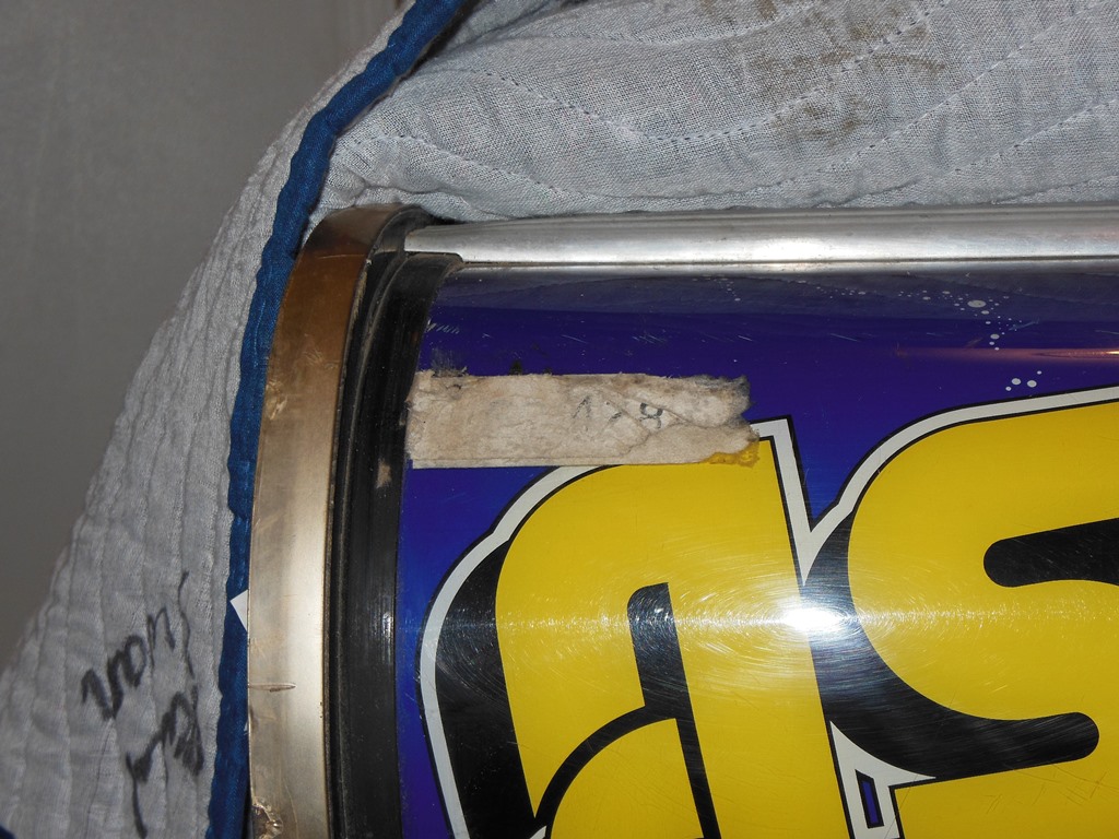
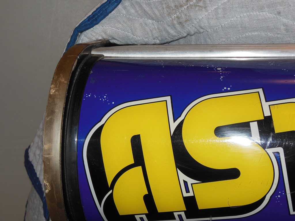
The marque was in pretty good condition except for some surface scratches and old label (actually more than one label on top of one another) on the top left corner. Soaking with De-Solv-it (a citrus based solvent, suitable for plastics but not for metals) and working at it with an old credit card gradually brought off the label and glue goo.

|
Since I'd cleared the garage out ready for the repair party I was hosting, I took the opportunity to fit castors to the base (two of the feet were already missing). At the repair party, Bill Witzel kindly used his Hakko de-soldering tool to replace all 12 of the remaining original red Cambian ROM sockets for me to fix an intermittent crashing issues. The game ran fine for the remainder of the party :)

|
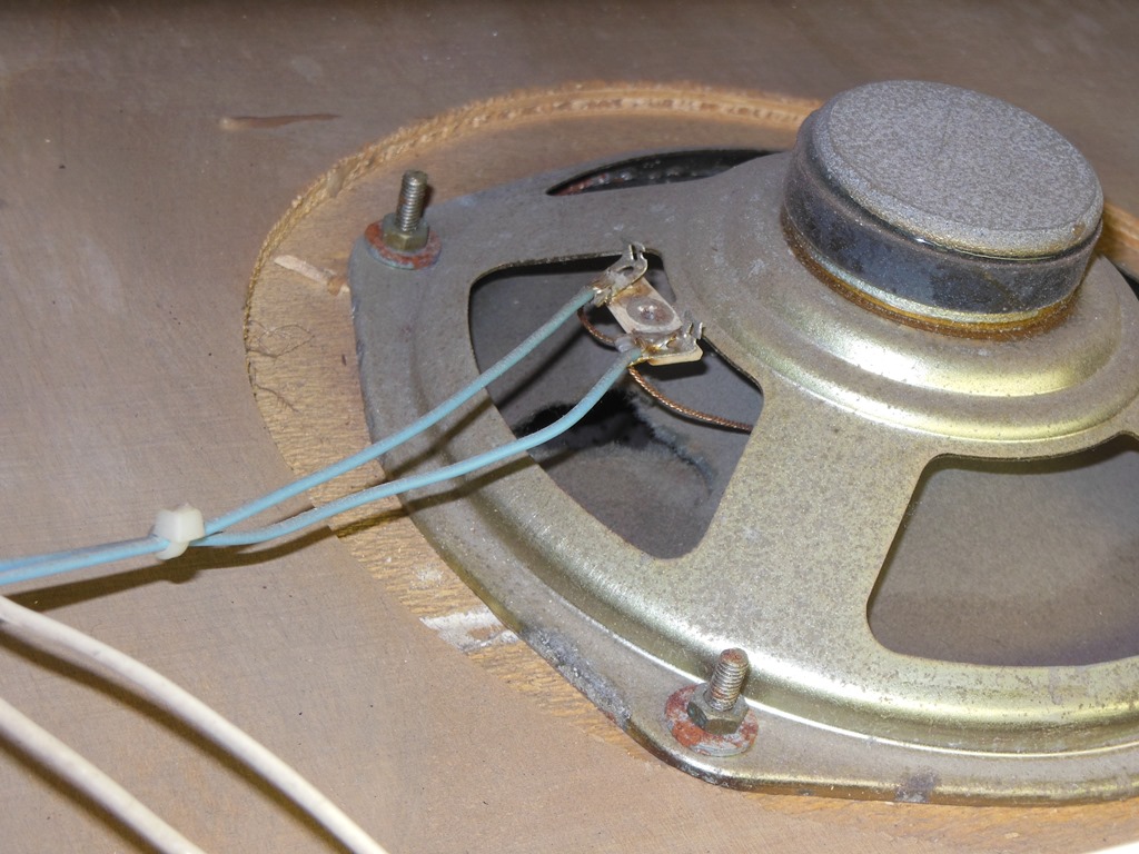
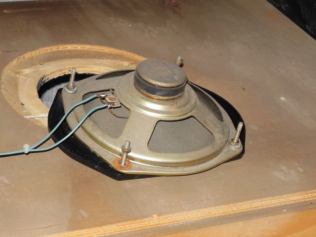
The speaker in the cab was damaged so I replaced it with a good one from one of the cabs from the Duke of Lancaster.

|
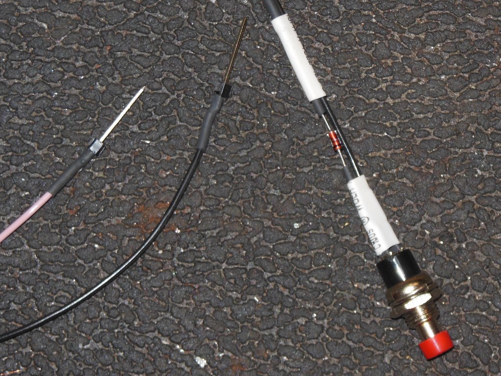
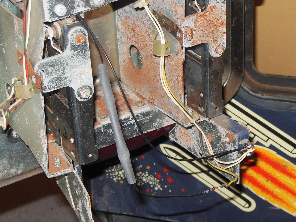
The credit button needed a diode adding to the button wiring to be compatible with the matrix inputs used on this game. I covered it with a shrink tube (that I left un-shrunk) and cabled tied the wires neatly.


|
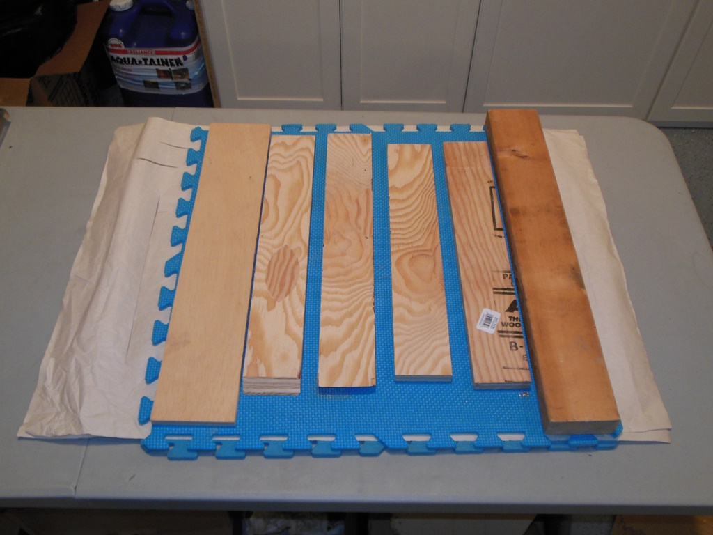
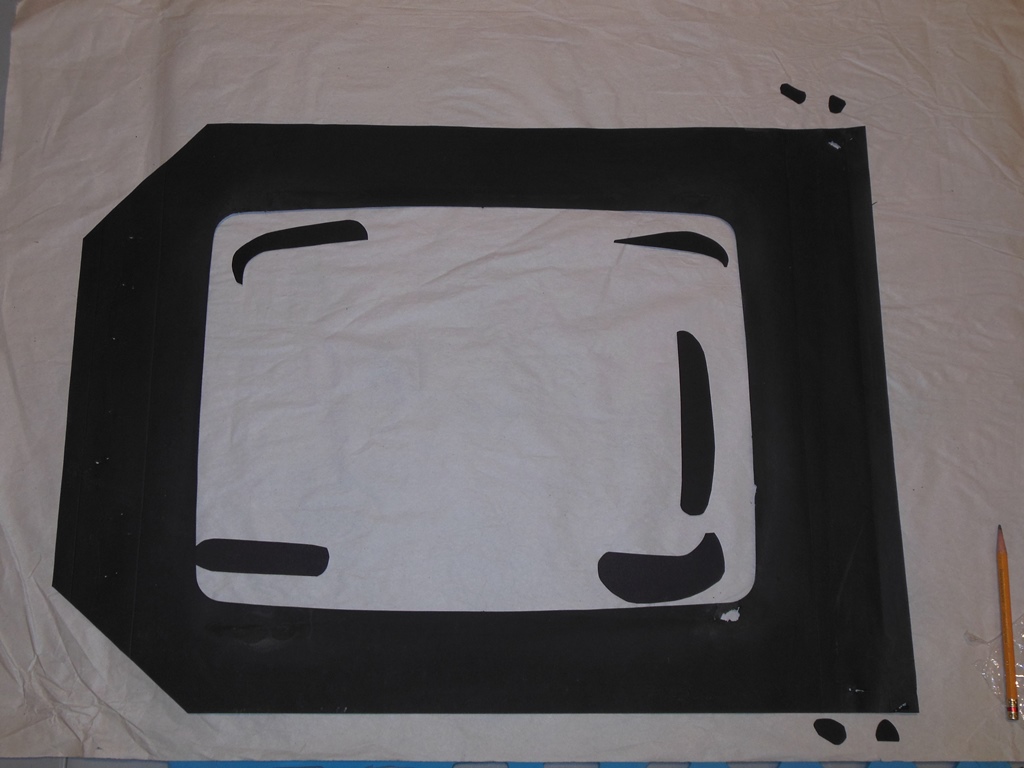
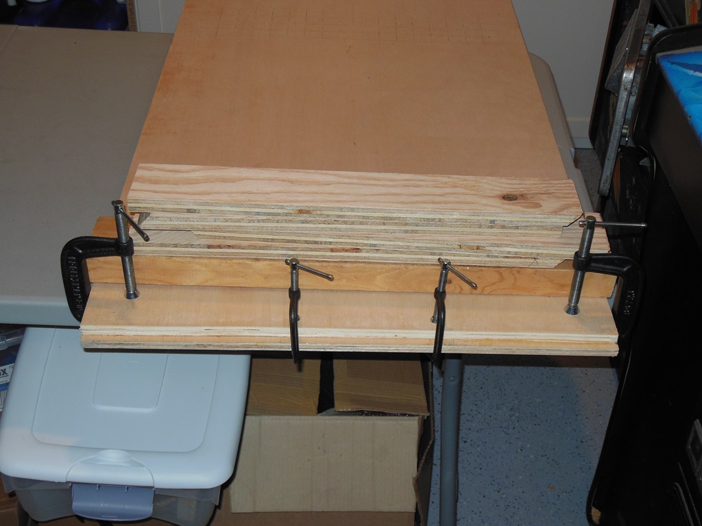
The nice folks at Home Depot once again used there board saw to cut a back door out of a plywood panel. The original door has vent slots cut however since I don't have a router I marked holes in the same places to use a matrix of plain round holes instead.
|
The original door was about twice as thick as the plywood panel I had, however that did allow me to glue on an off cut to make the lip at the bottom

|
I needed to add a couple of spacers so the door would sit properly on the side guide rails in the cabinet. One of those spacers I needed to make a little wider than the other in order to cover the power interlock switch.
|
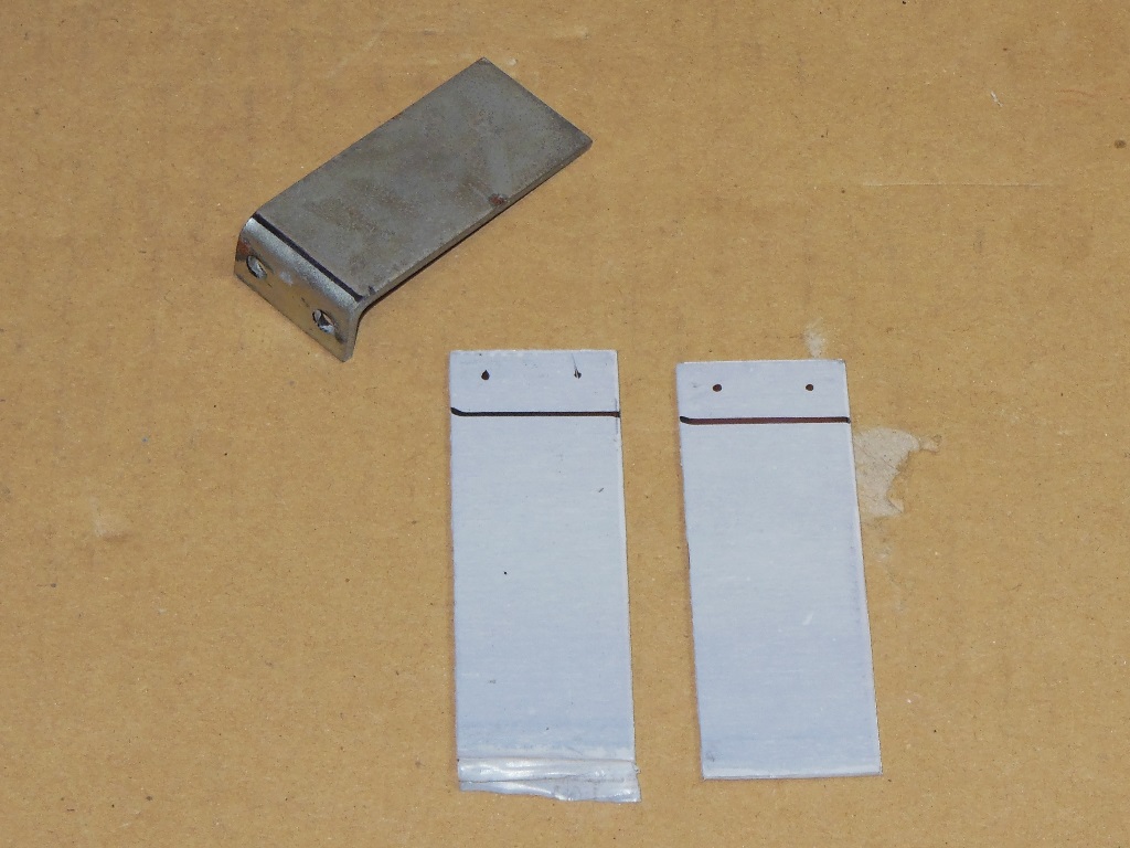
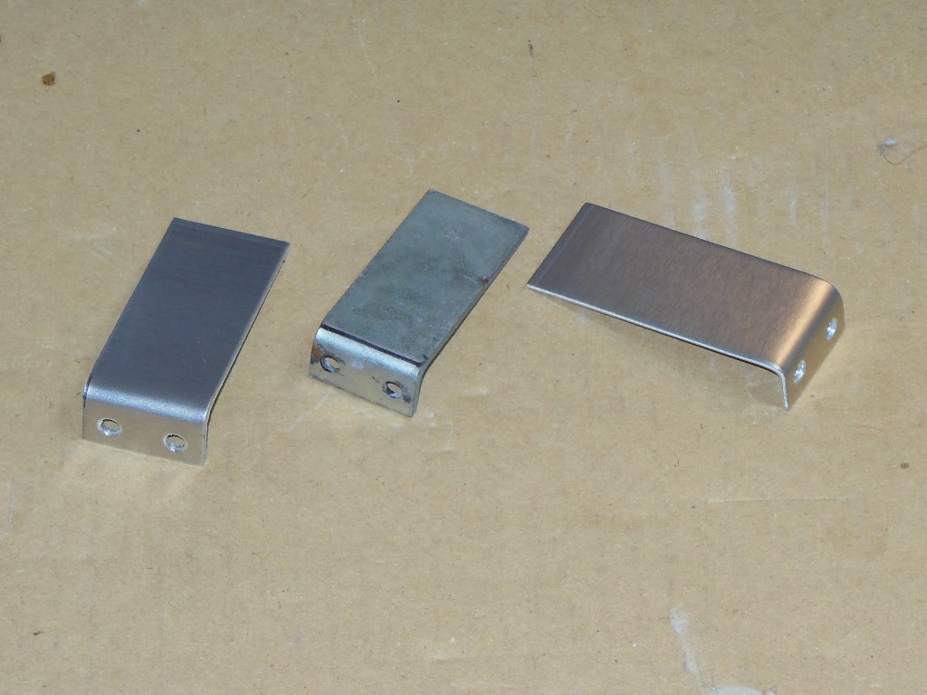
As noted previously with the Super Galaxians all the cabs except one were missing the PCB mounting brackets that keep the sound and main PCBs secured in their guides. Using the stack of aluminium plates bought earlier I made another two reproduction brackets for this game and fitted them.
|
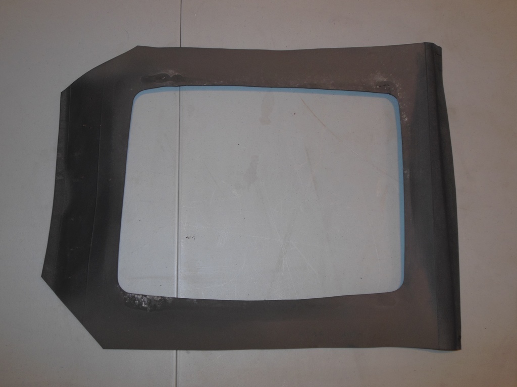
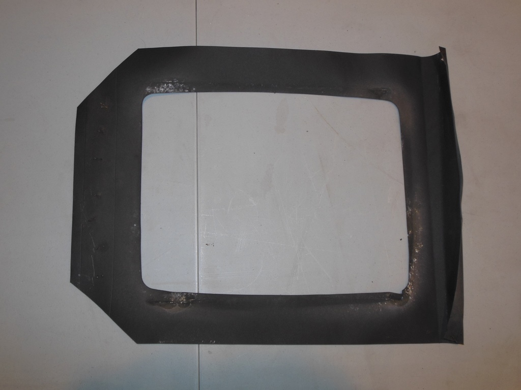
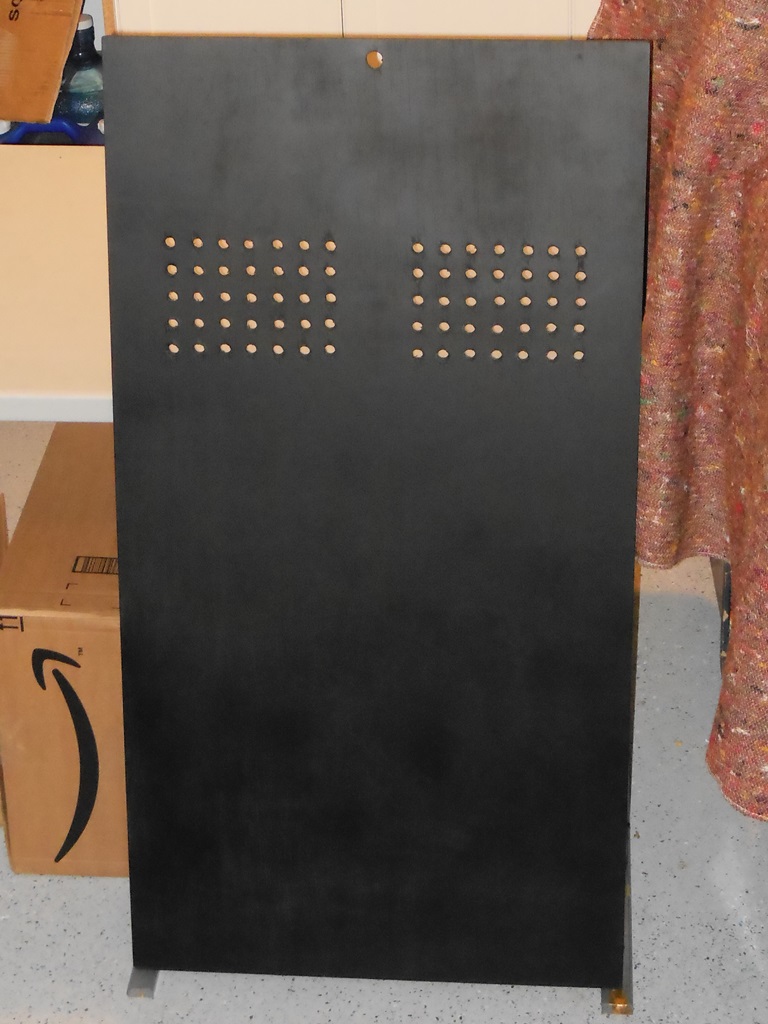
I primed and then painted the back door in matt black. The photo above shows the Sea Scare original back door on the right and the Astro Wars replacement back door on the left.
|
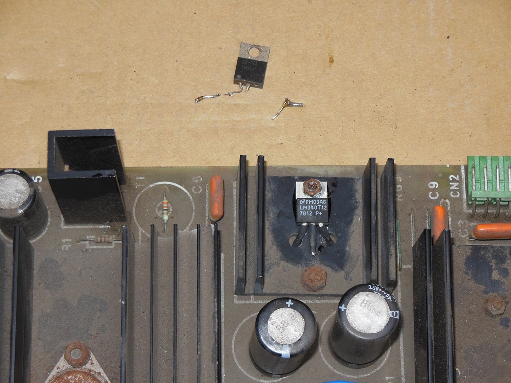
The LM340 had at some stage been replaced by cuting out the old one and soldering in a new one onto the pin stubs with wire bridges. It looked likely that this hack was going to fall apart or short out so I decided to properly replace it. As suspected, it did fall apart during removal.
|
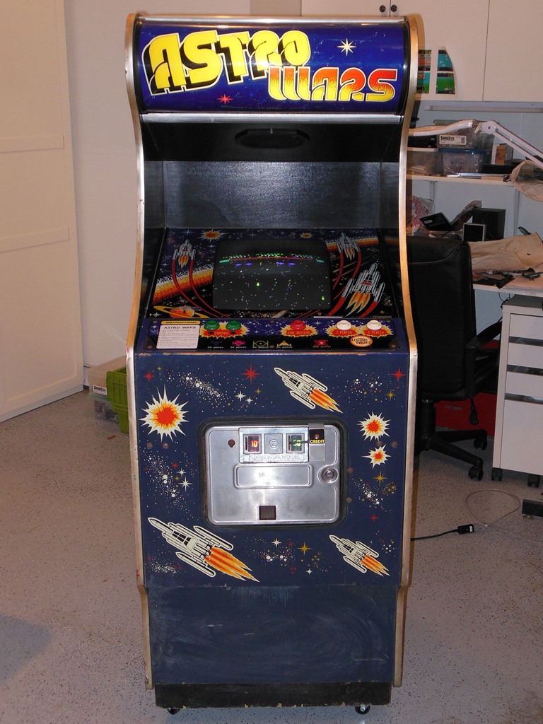
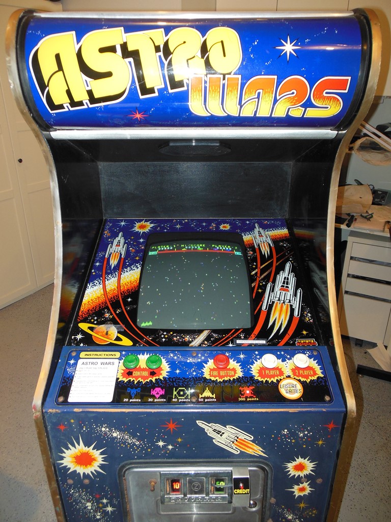
Finshed the final monitor adjustments, burn in test and pre-show checklist.
A video of the Zaccaria Astro Wars game in action on this cabinet.
|
Submitted for the first time into the show the game stopped booting after a few hours. Though I didn't have time to investigate it at the show at the time, the problem turned out to be that the game board power connector had shaken loose during transport and pushing it back in fixed the game.