
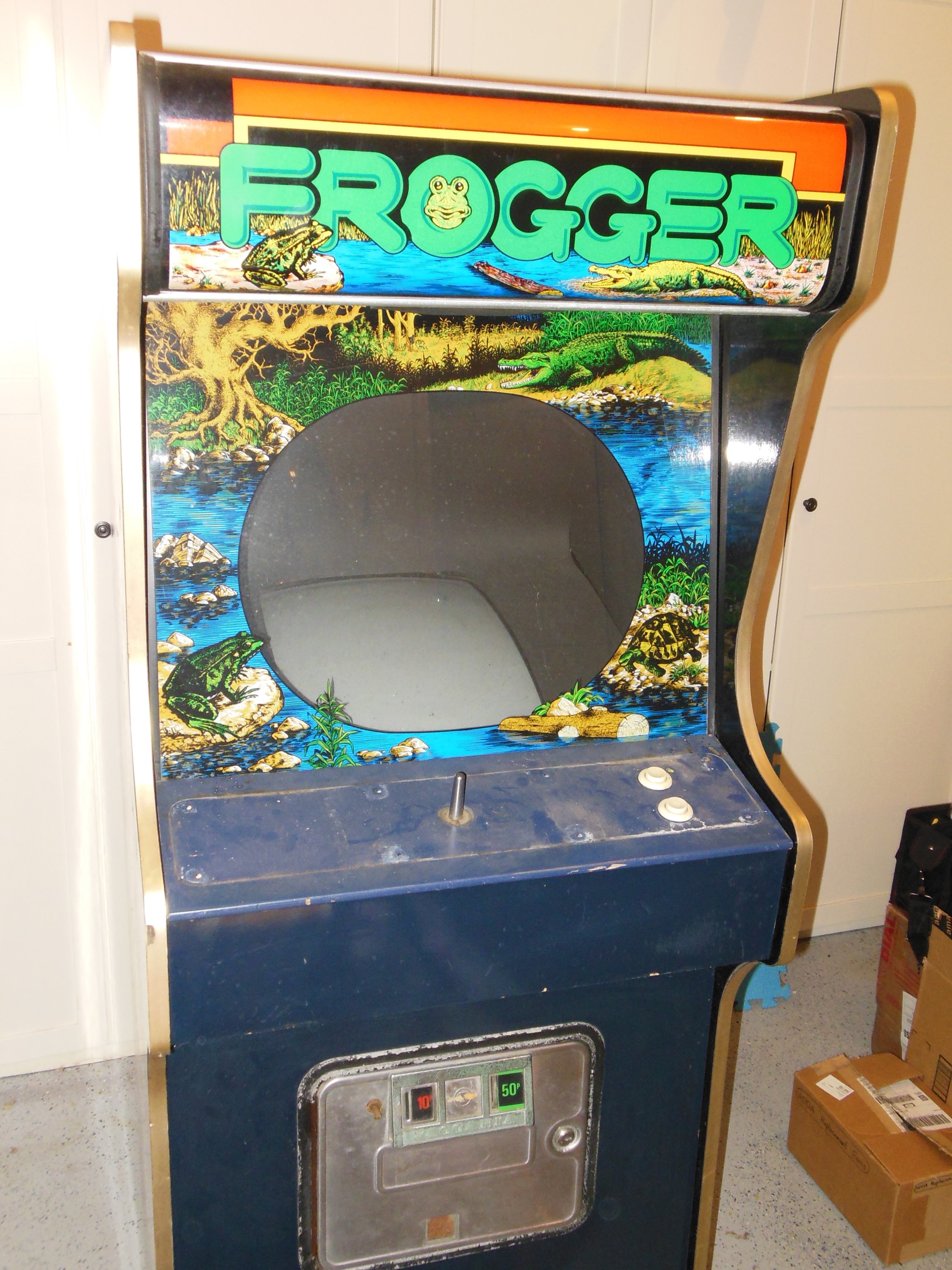

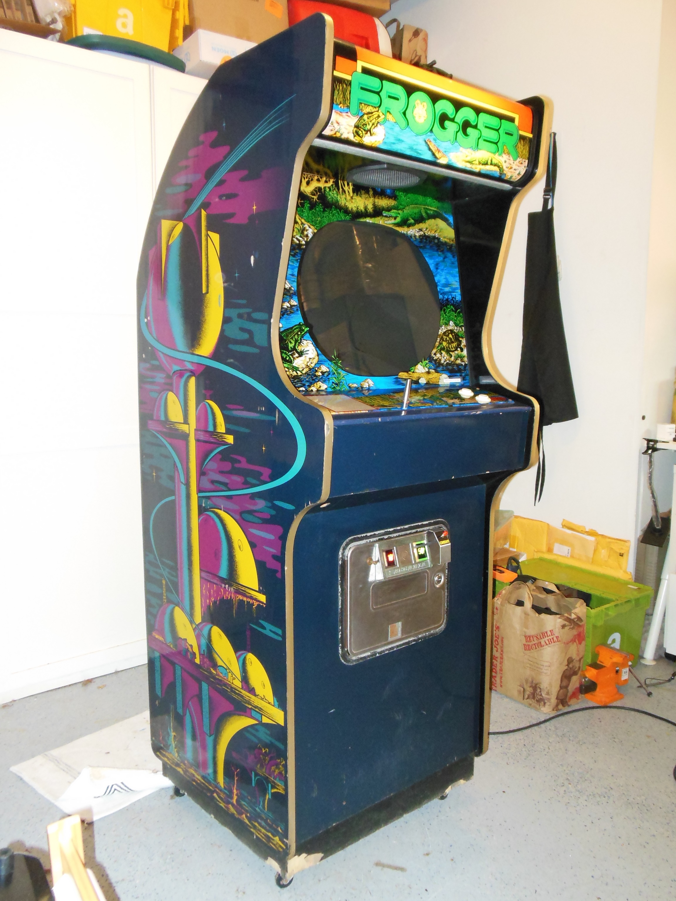
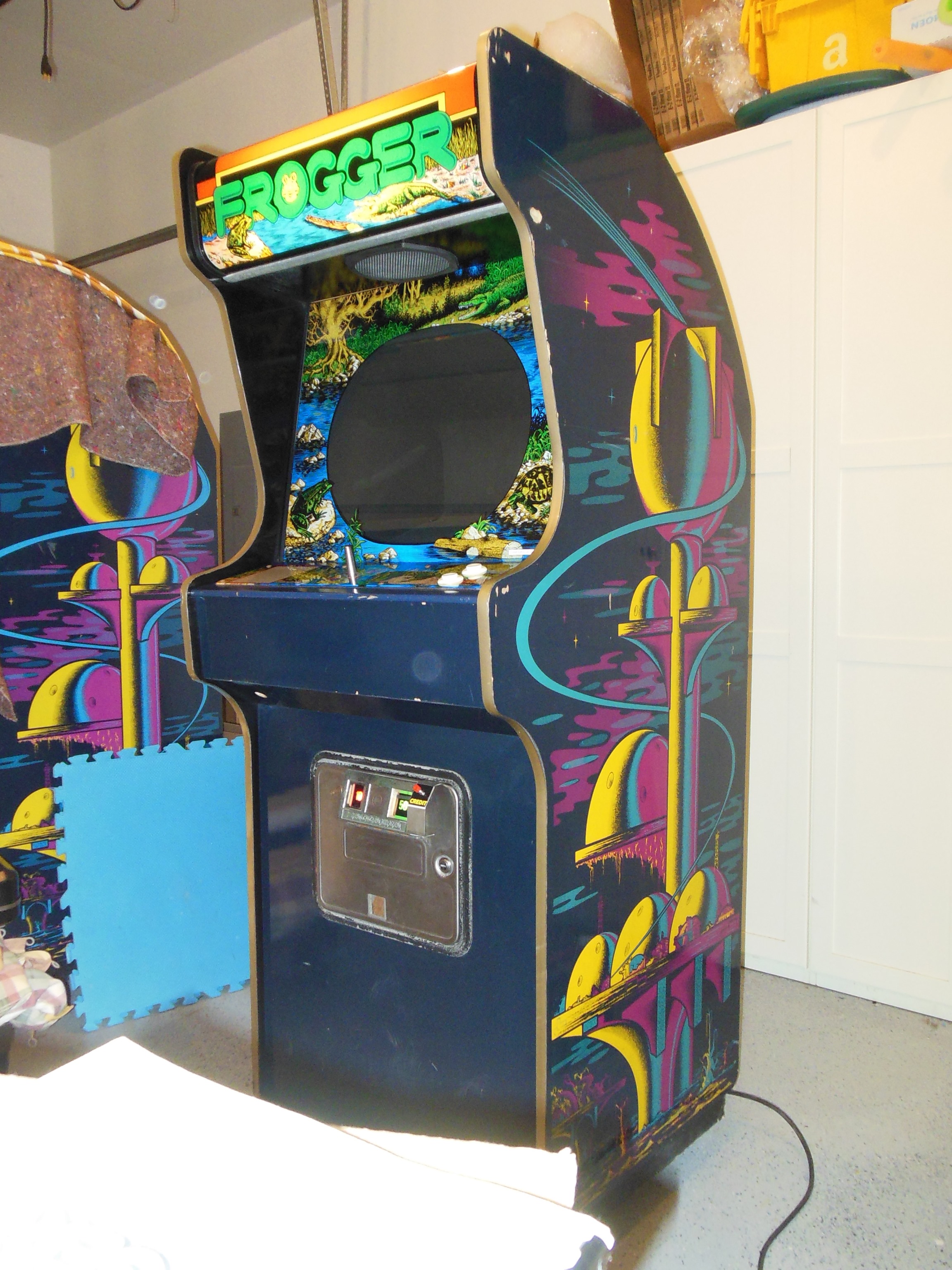
This UK configured Frogger upright I acquired in the early days of collecting Zaccaria arcade games in the late 90's. It had a first round of basic cleaning & repairs to get it working after I got it in the UK.
|
|
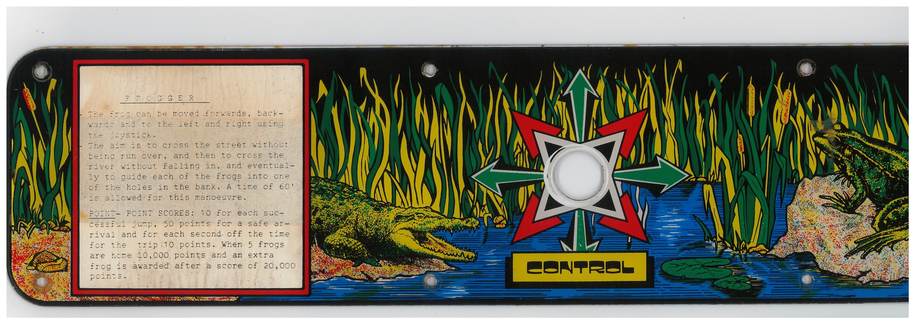
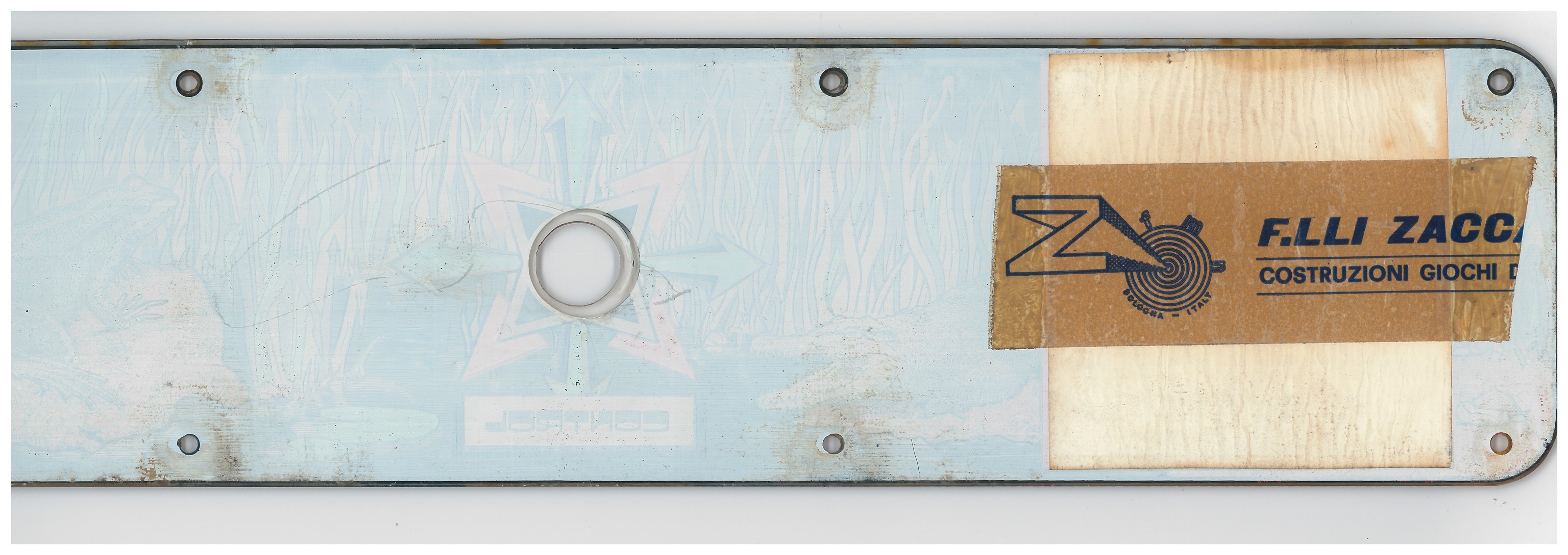
The exterior was in good condition with very few scratches, dings or missing T-molding. The control panel overlay I had removed to scan (probably the first piece of Zaccaria artwork I ever scanned) many years ago.
|
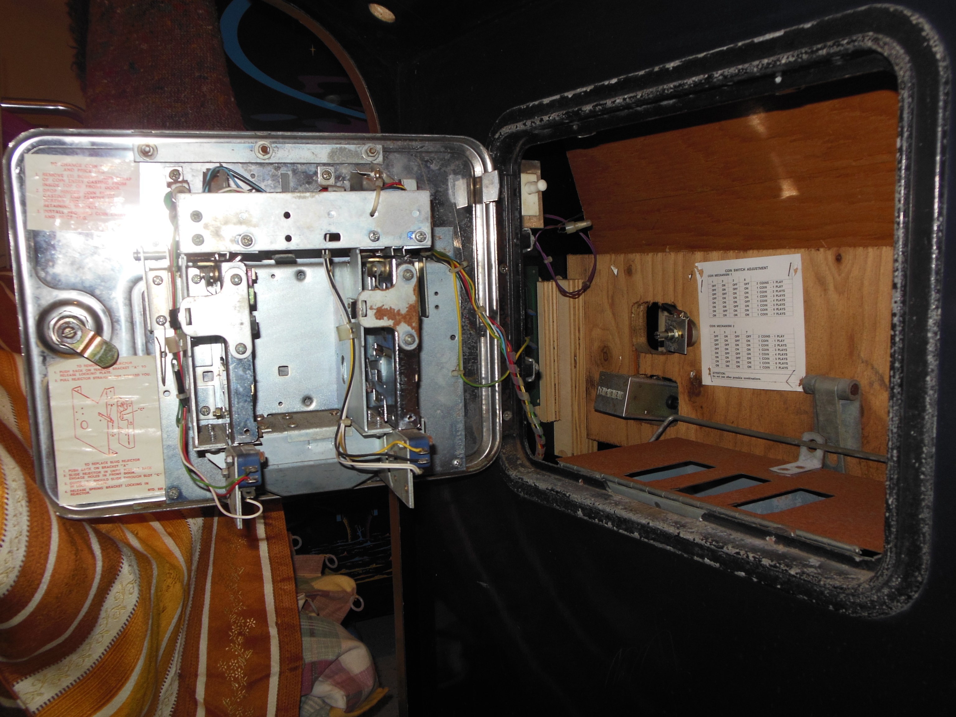
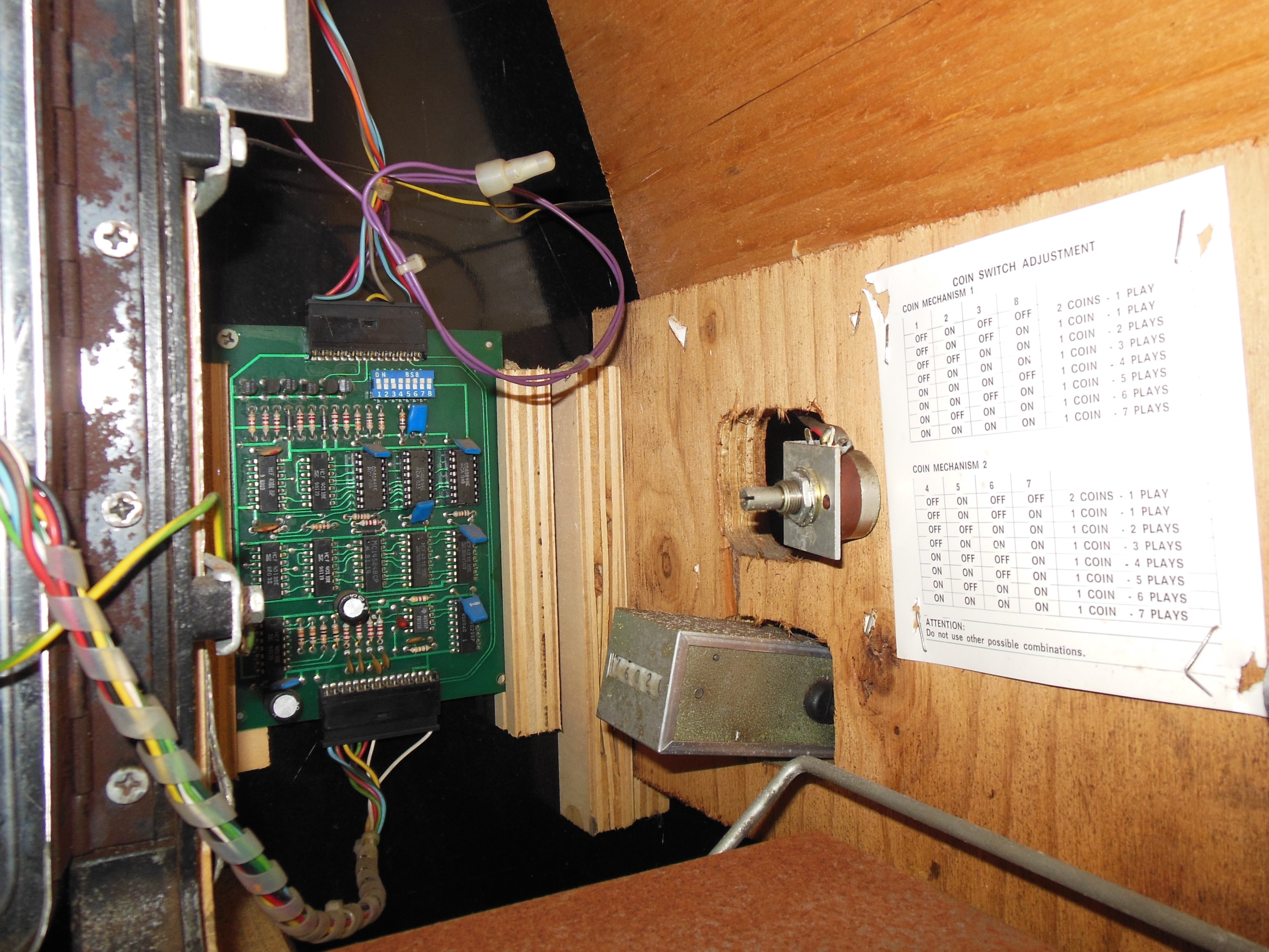
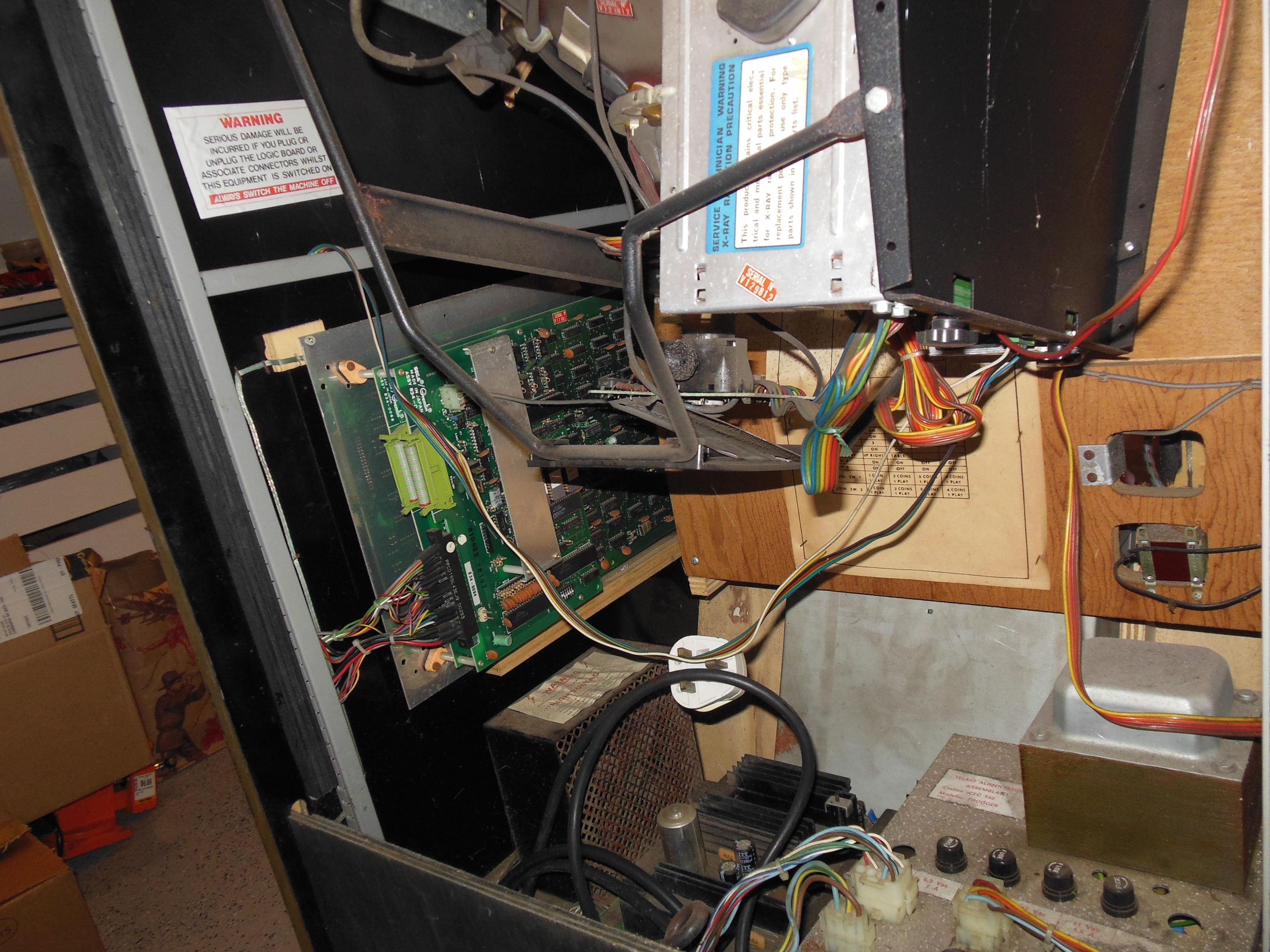
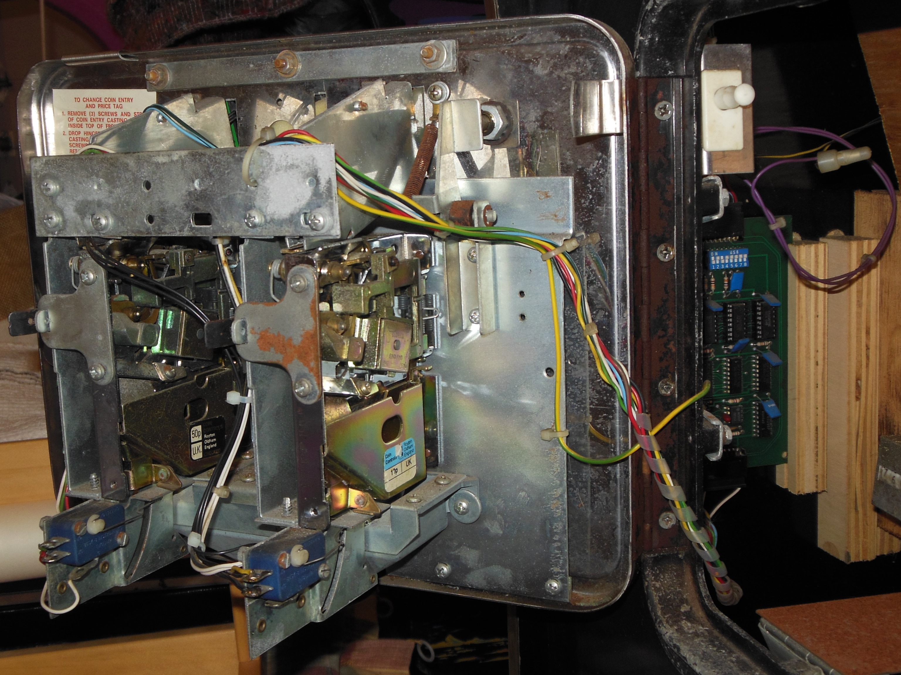
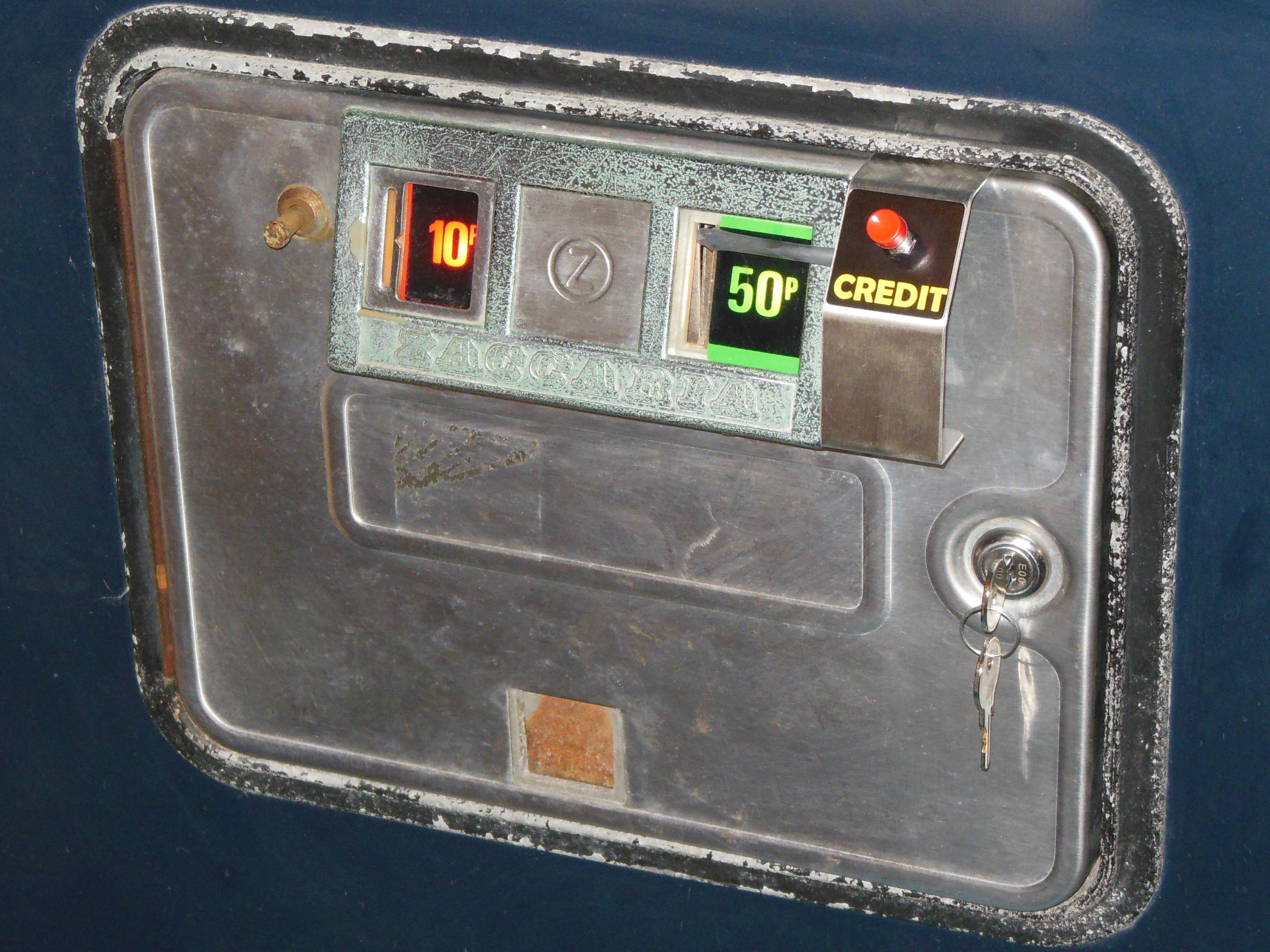
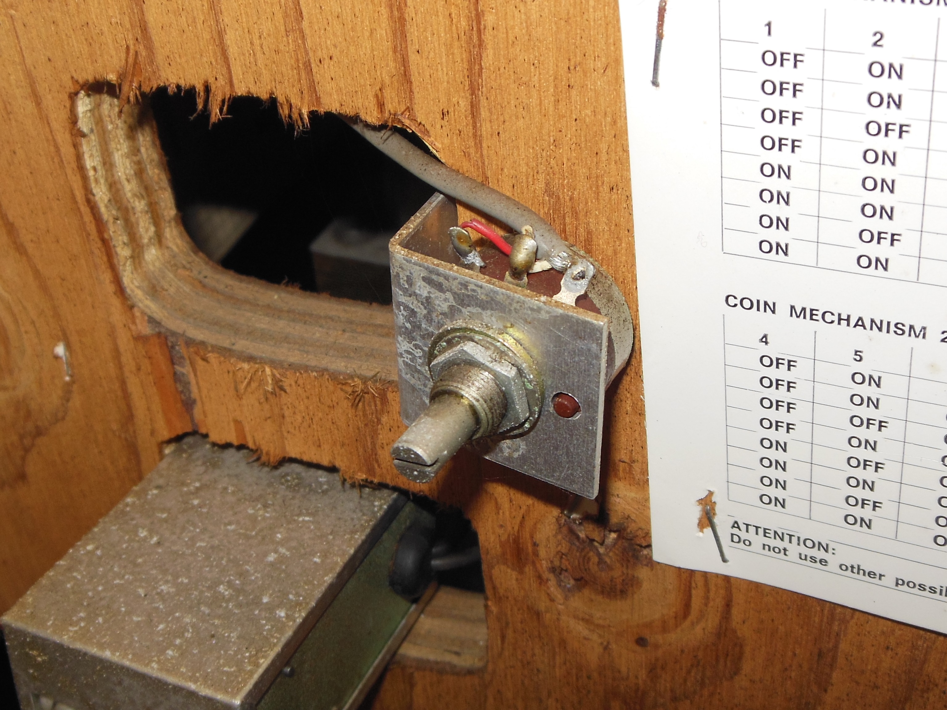
All the coin door & credit wiring looked complete and original. An external volume control was fitted. Interestingly the credit switch settings sheet had been moved to the right to open up the 2nd coin counter slot for the volume control.

|
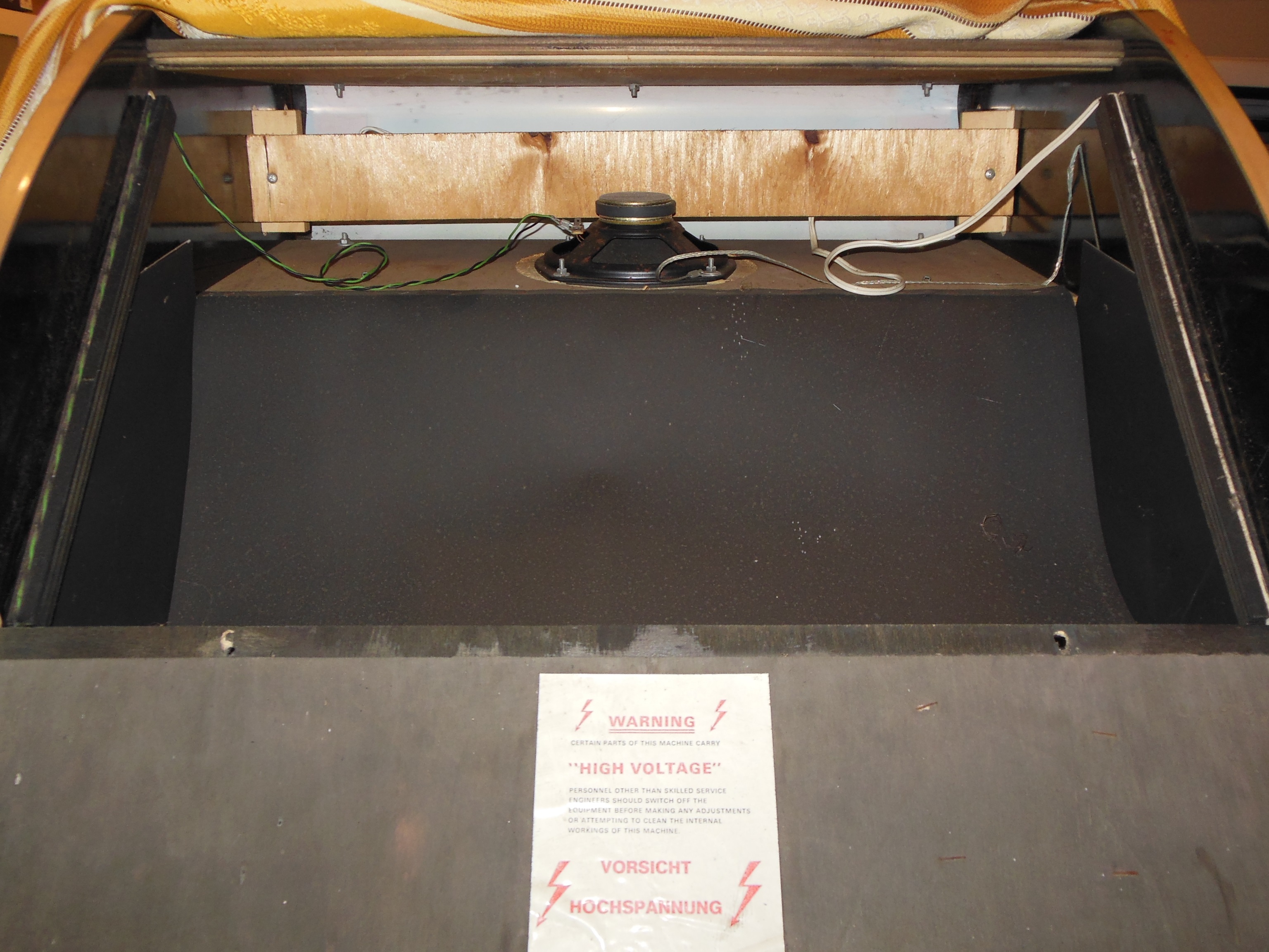
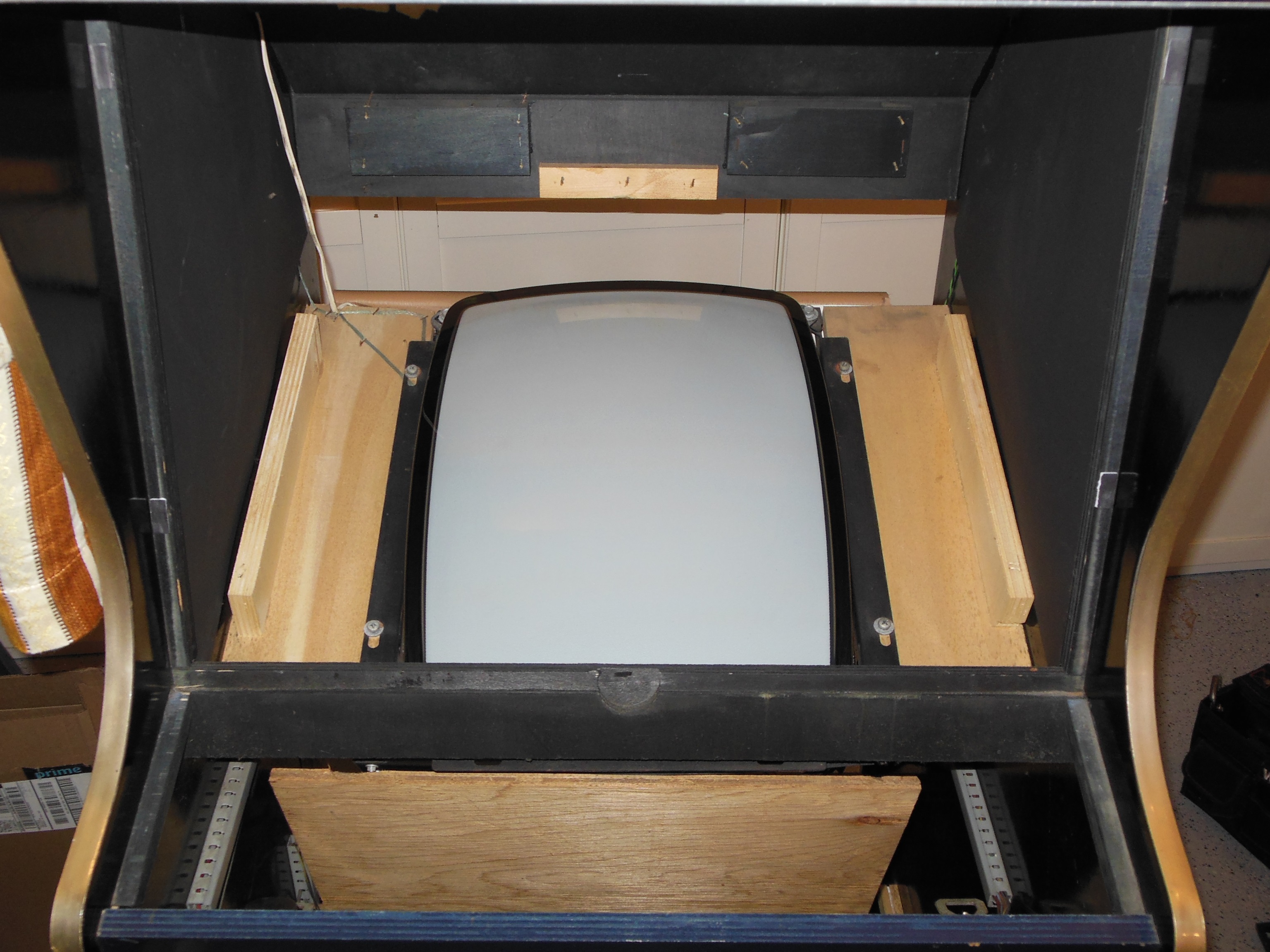
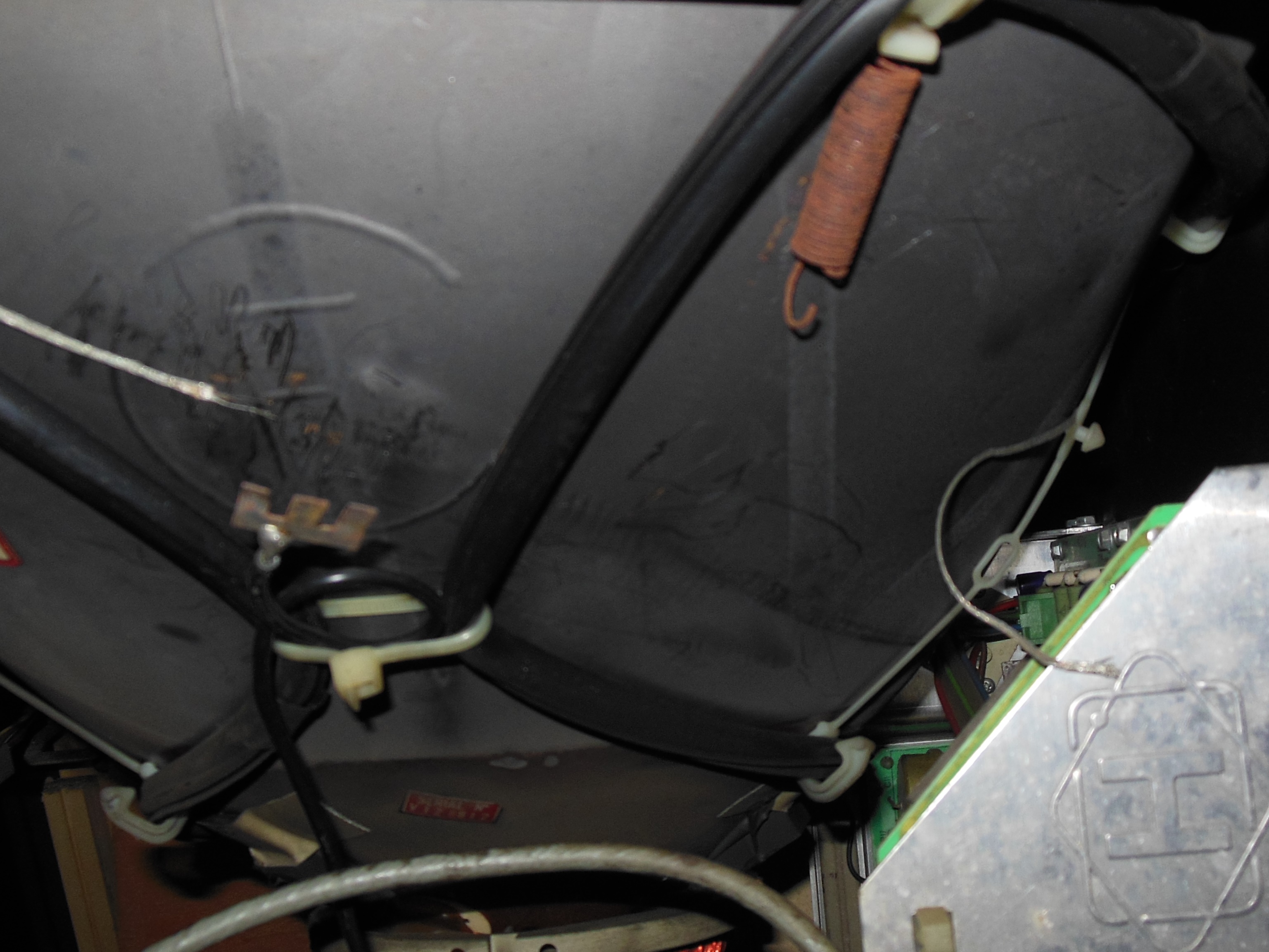
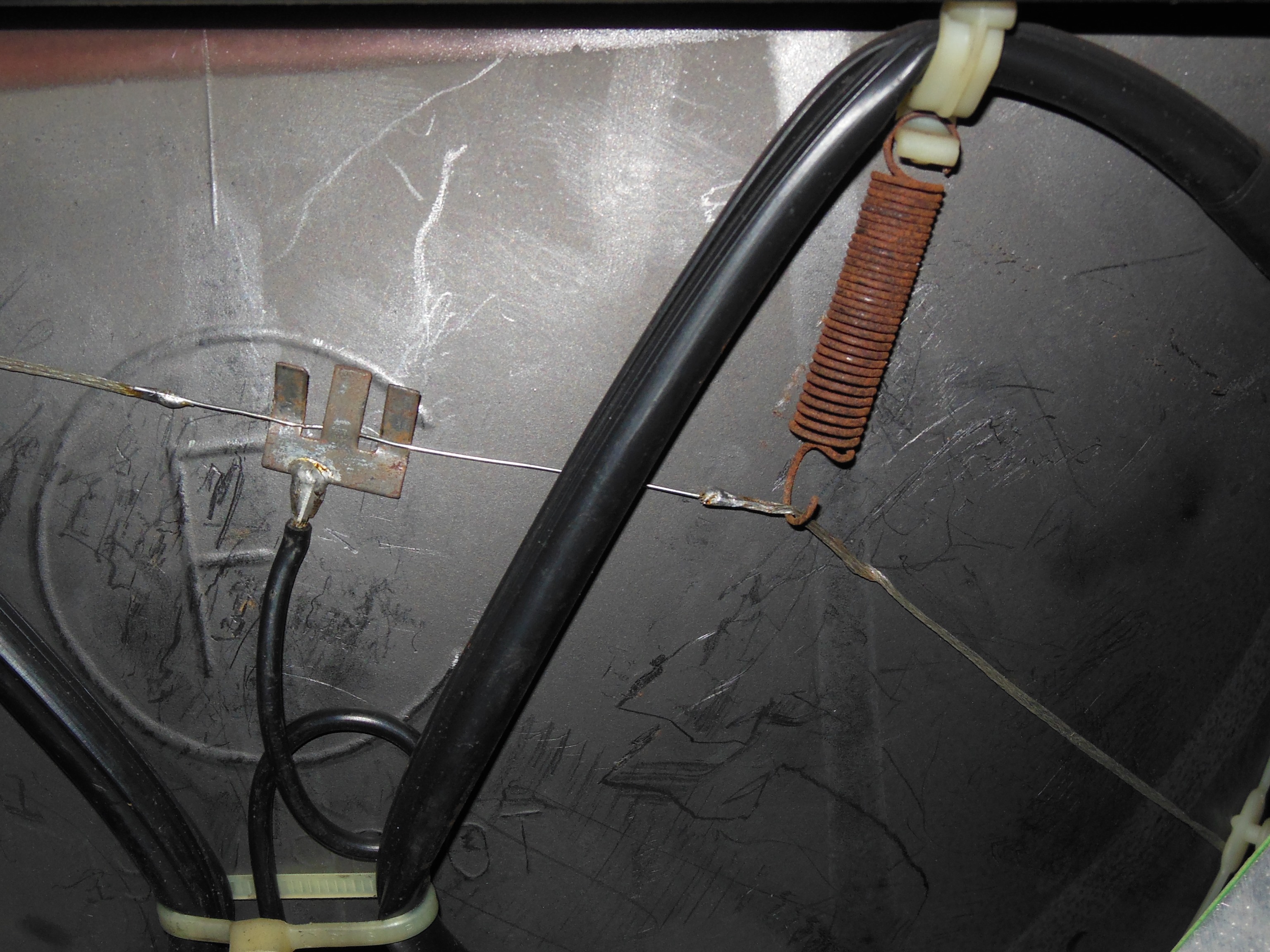
A protective sheet for the monitor was still present in this cabinet that I rolled up and zip tied to the monitor frame to keep it out of the way and unblock the back door air vent.
|
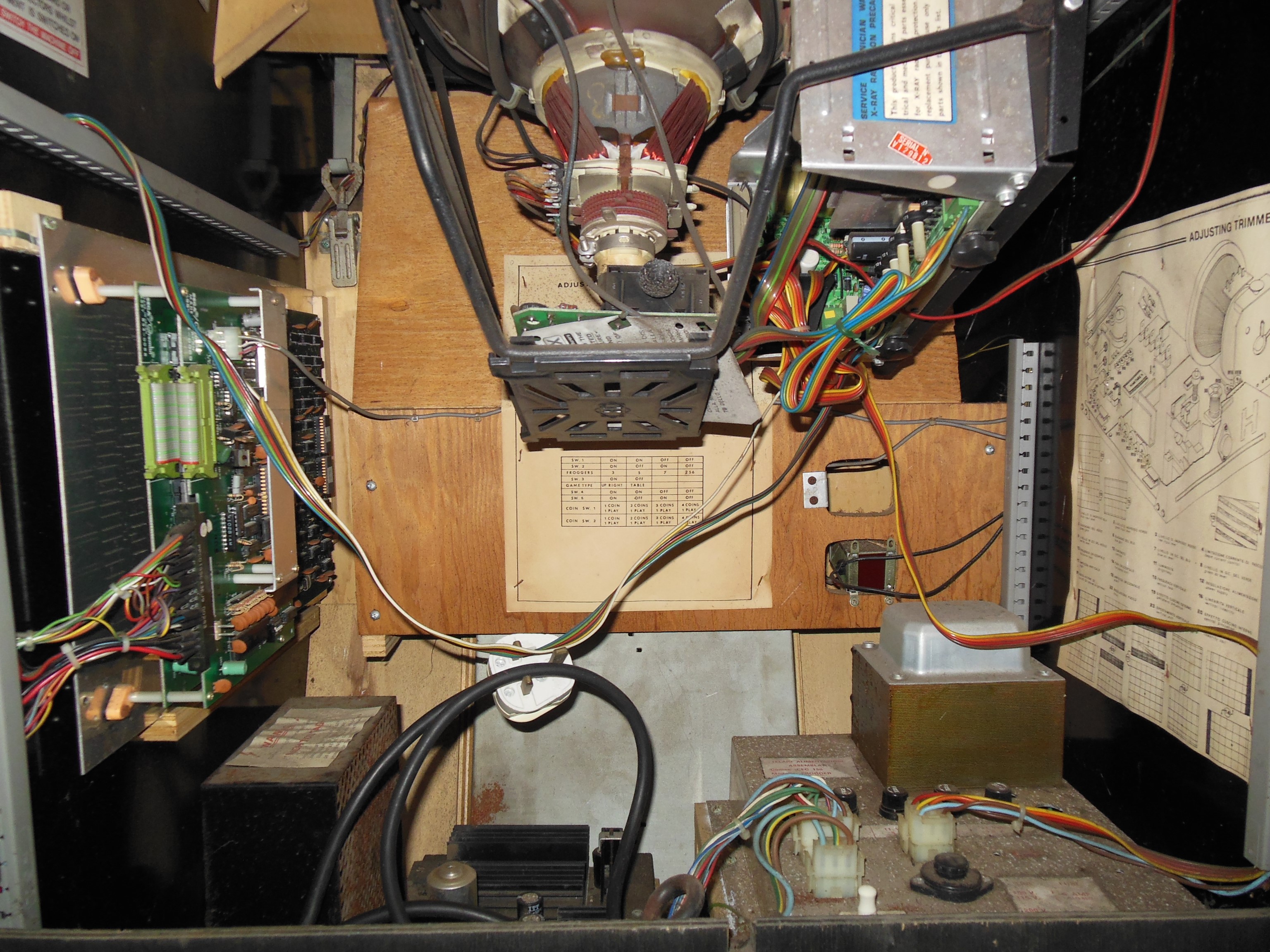
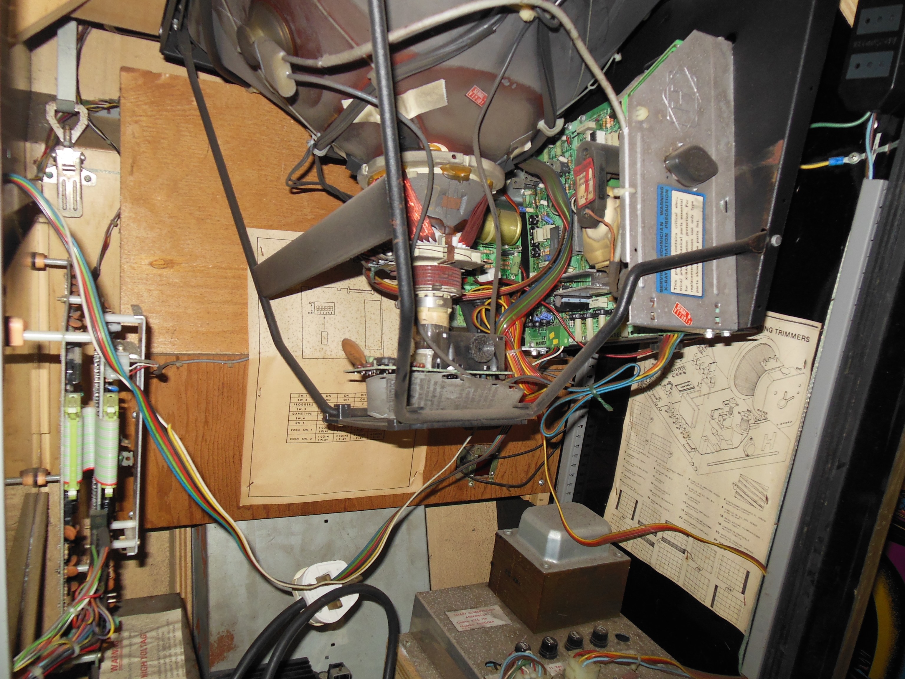
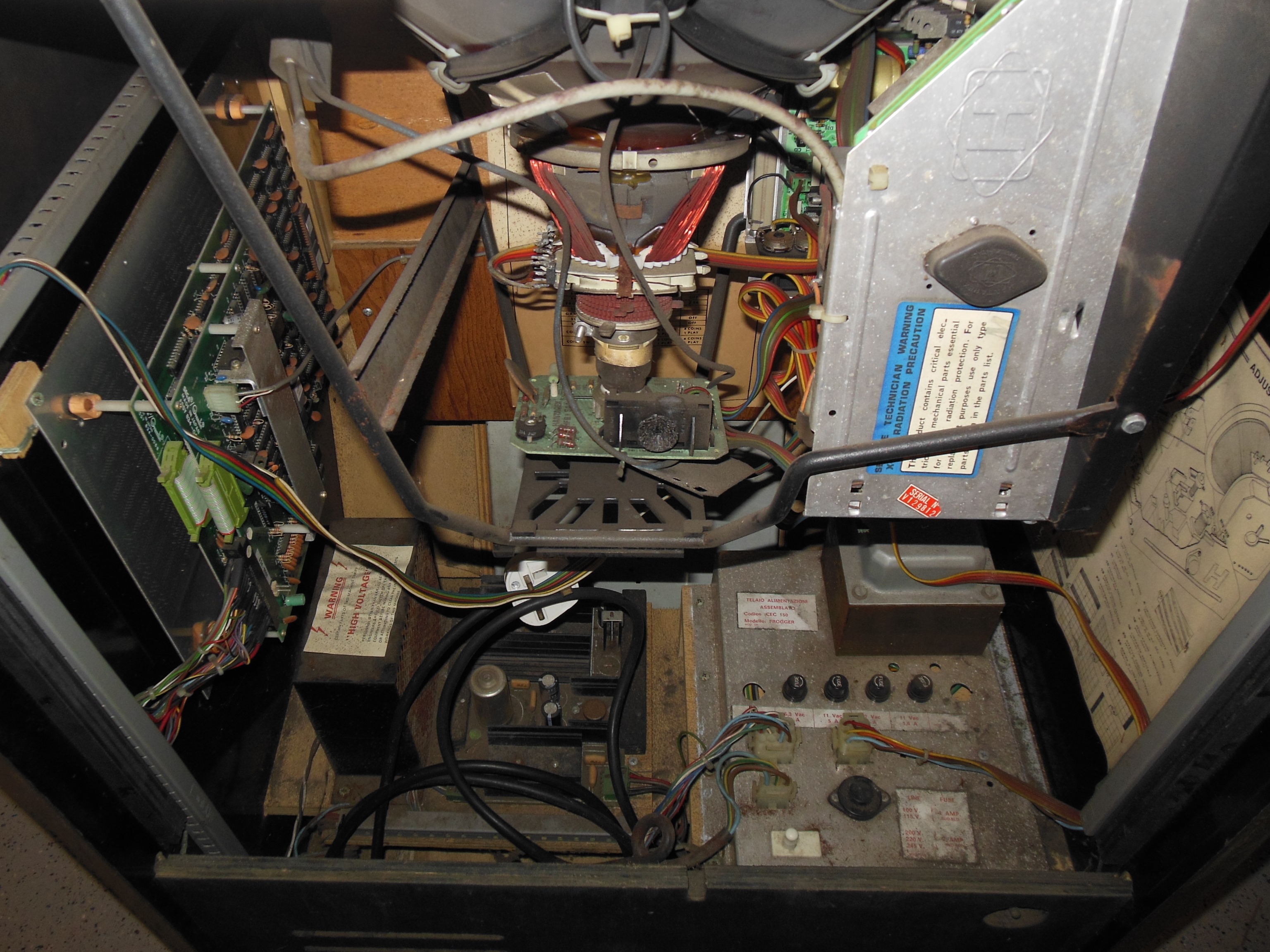
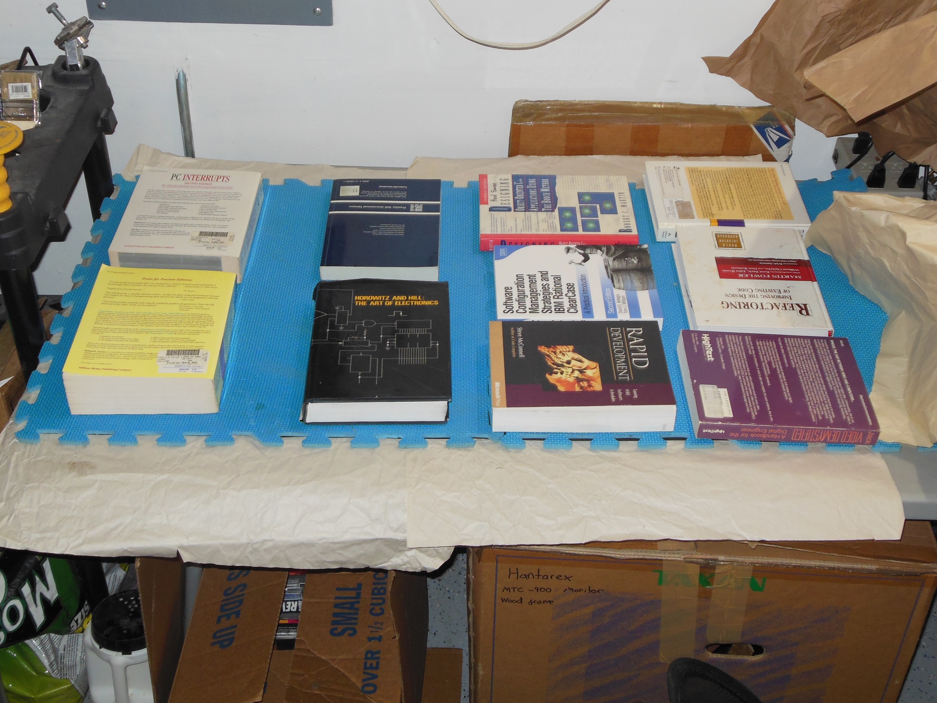
As far as I could tell the inside was complete and all original including all the adjustment sheets.
|
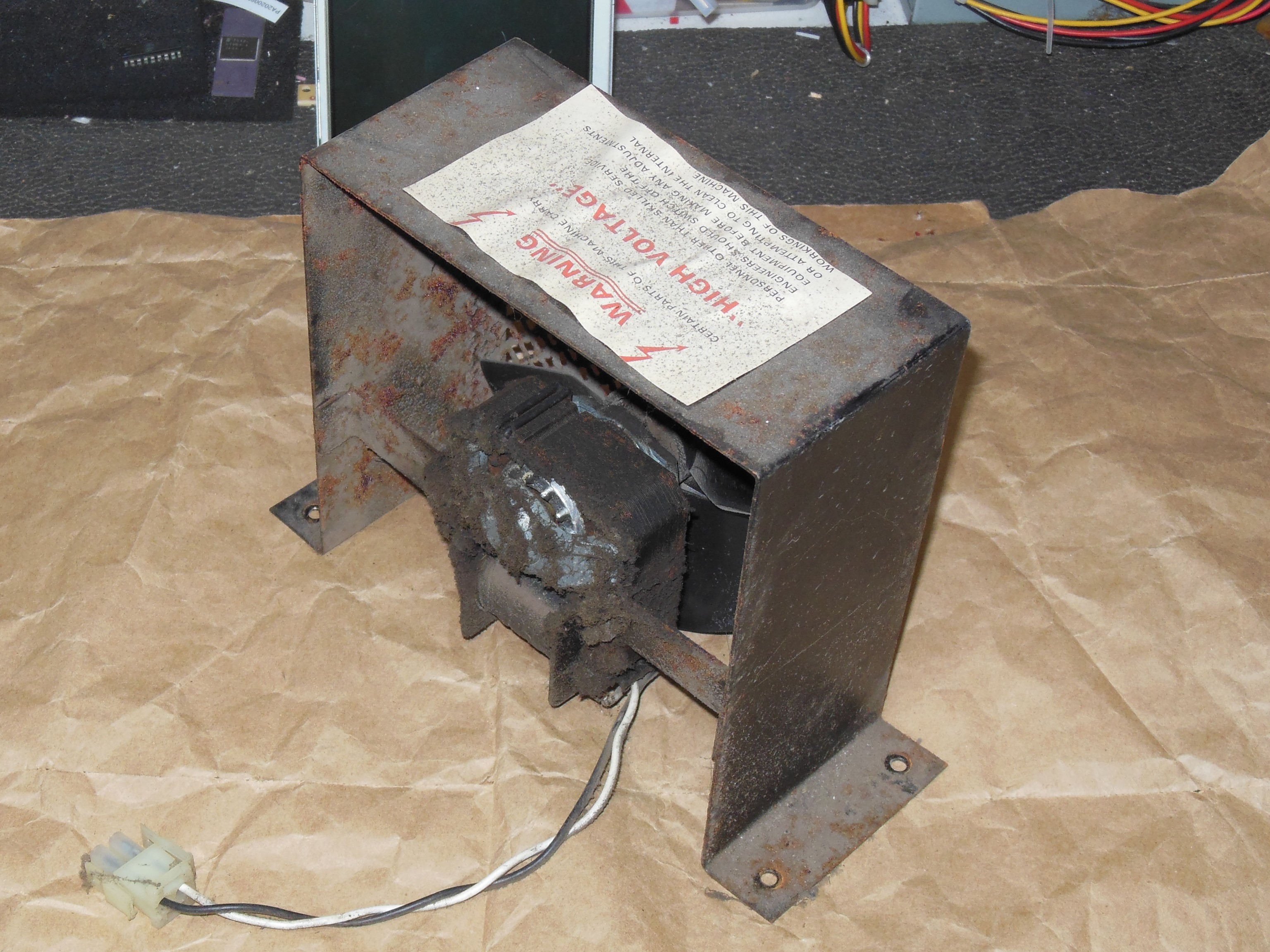
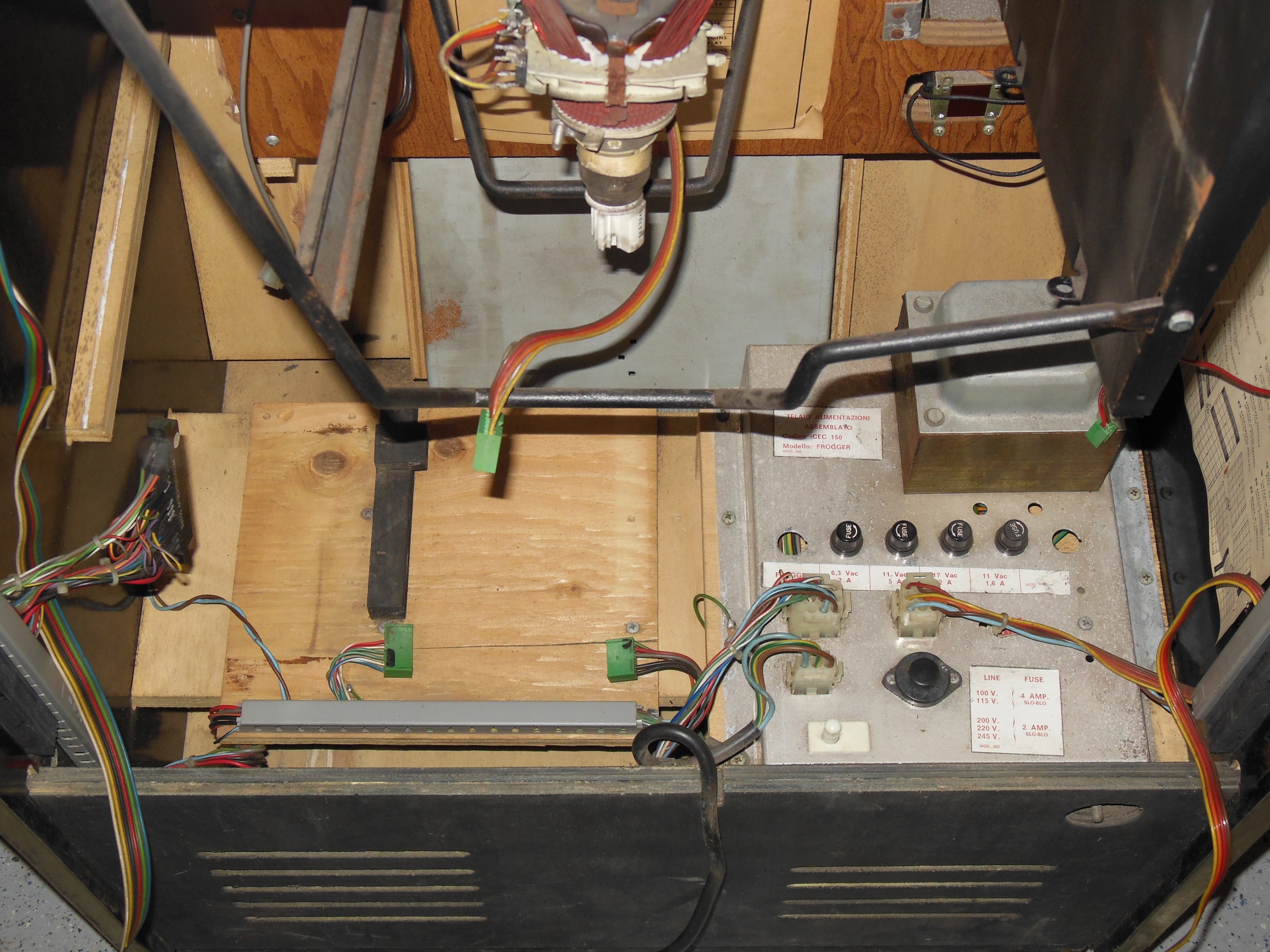
The power supply assemblies looked complete and original but very dusty. The power transformer block was labeled CEC-150 & Frogger. Comparing with Super Cobra CEC-137, one difference was that CEC-150 has a 5A 11 VAC fuse and CEC-137 a 4A 11 VAC fuse.
|
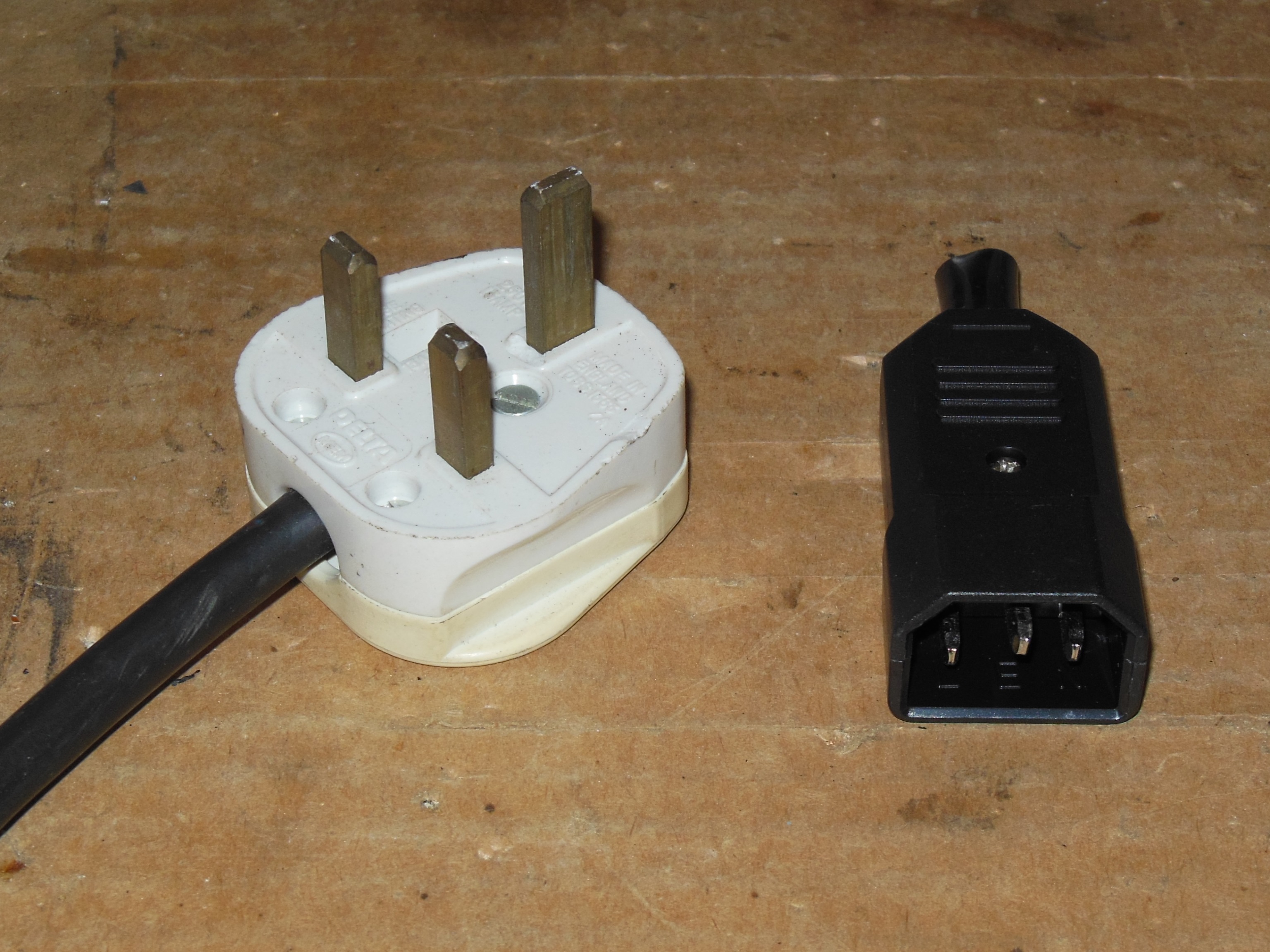
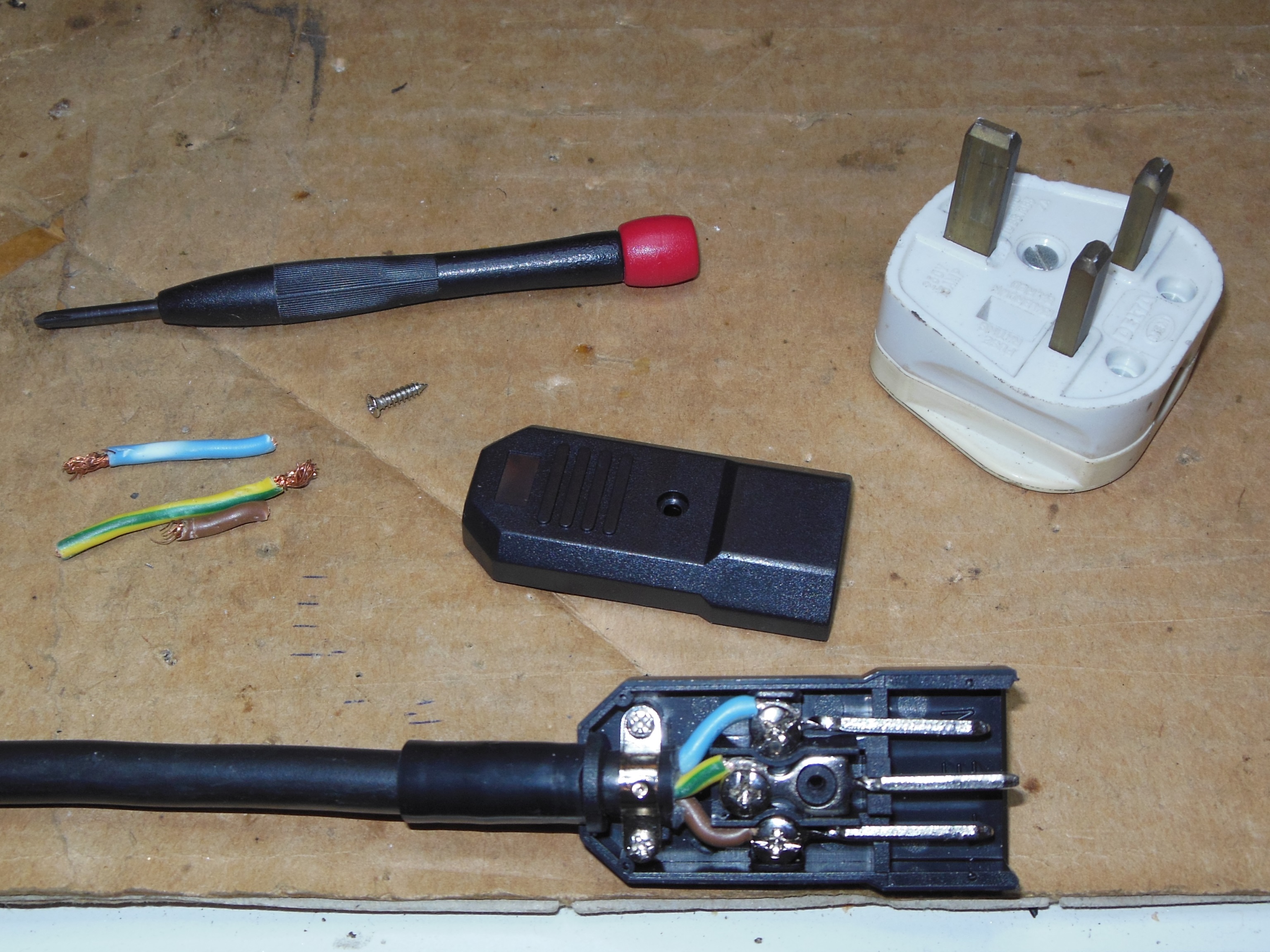
The UK mains plug was replaced with an IEC-C14 plug for 240V use.
|
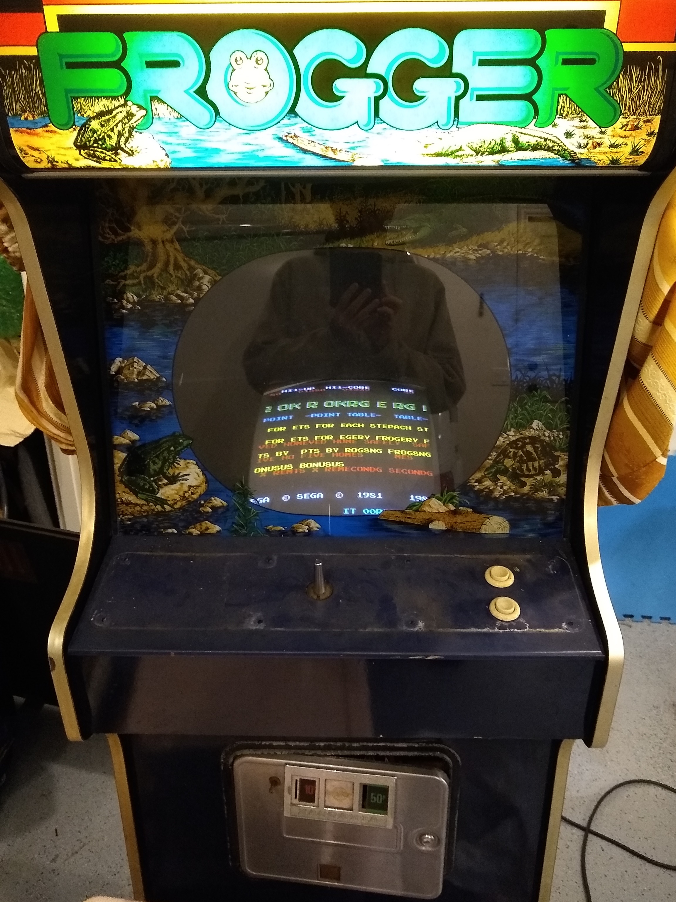
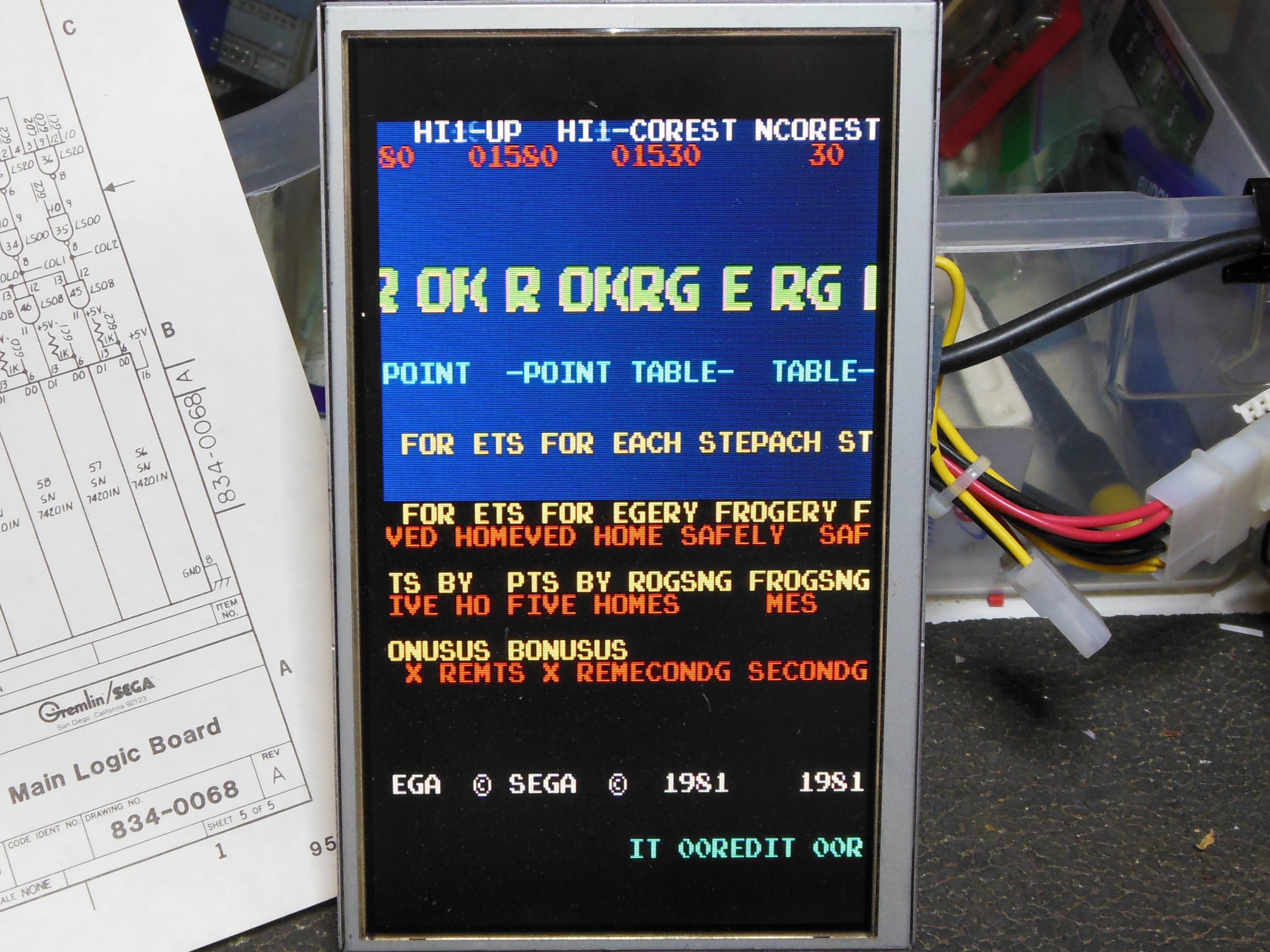
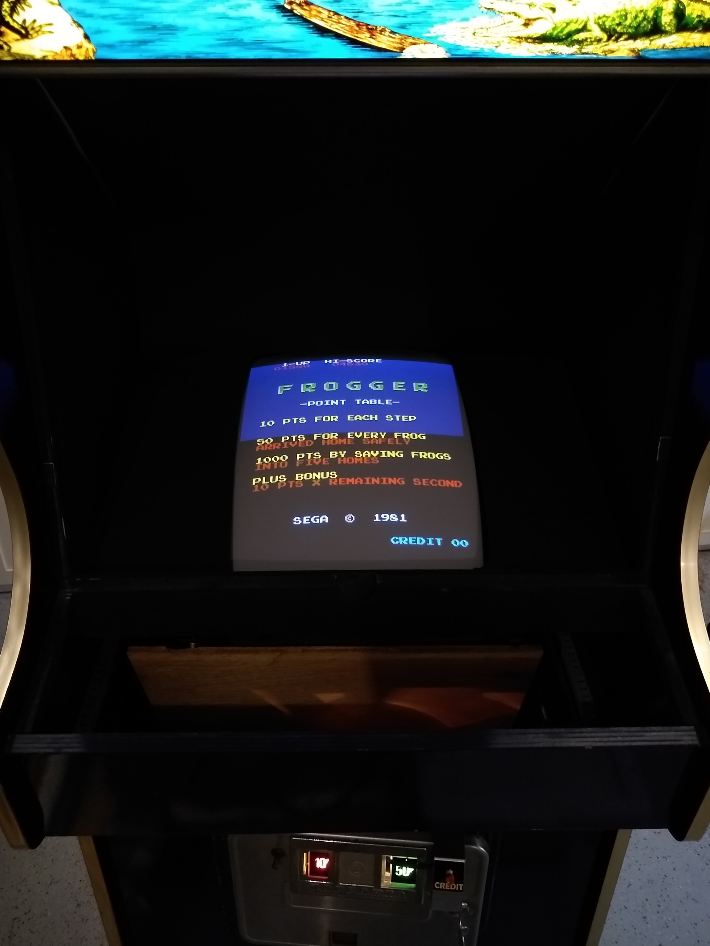
First power on was drama free - the monitor came on with a good picture and the marque light was working. There were a couple of issues - the Frogger game PCB had developed a graphics fault and there were no coin door lights.
|
|
The monitor glass had previously been scanned & reproduced by the community so there
was no need to scan this glass.
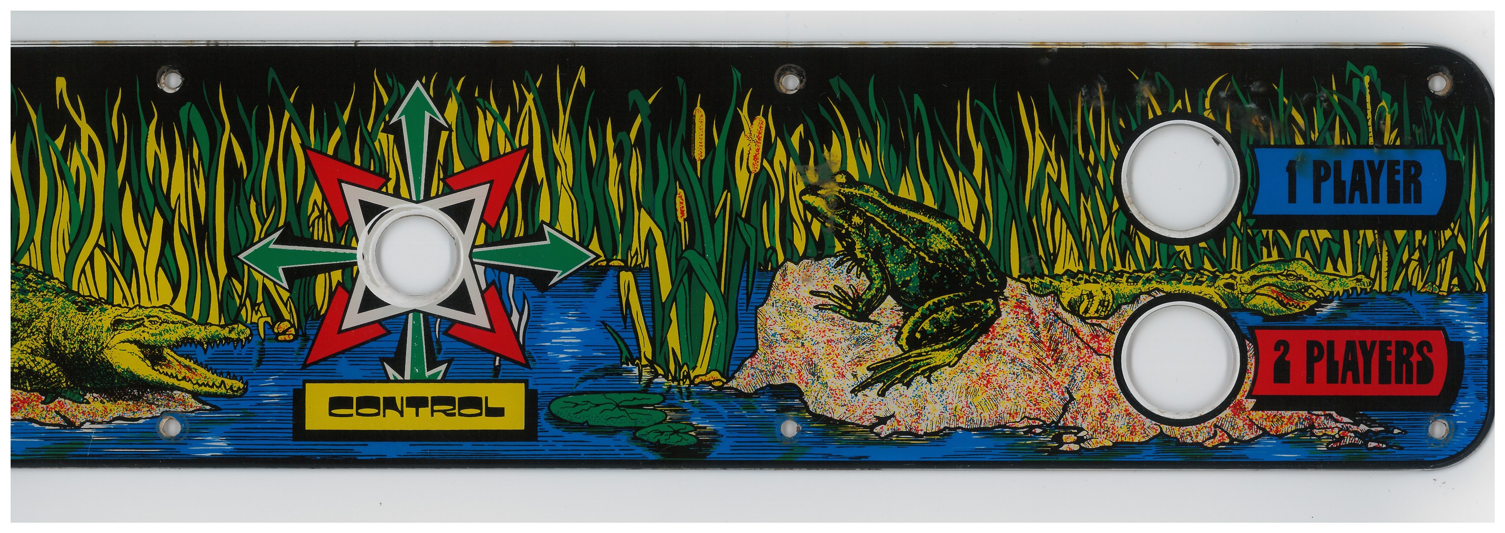
My old scan of this Frogger overlay was replaced with a new one in 2018.
600 DPI Frogger control panel overlay scan (29.3MB).

|
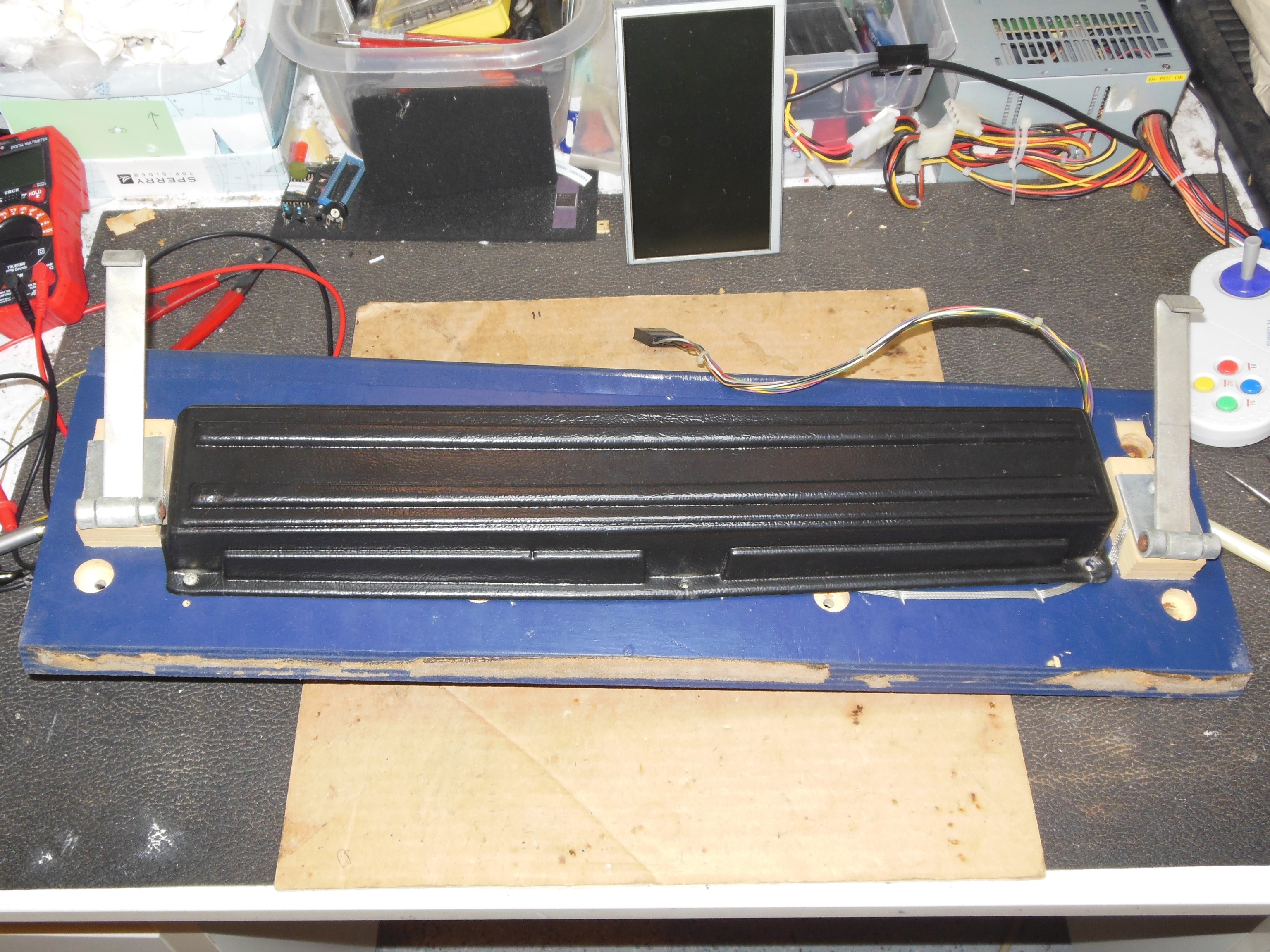
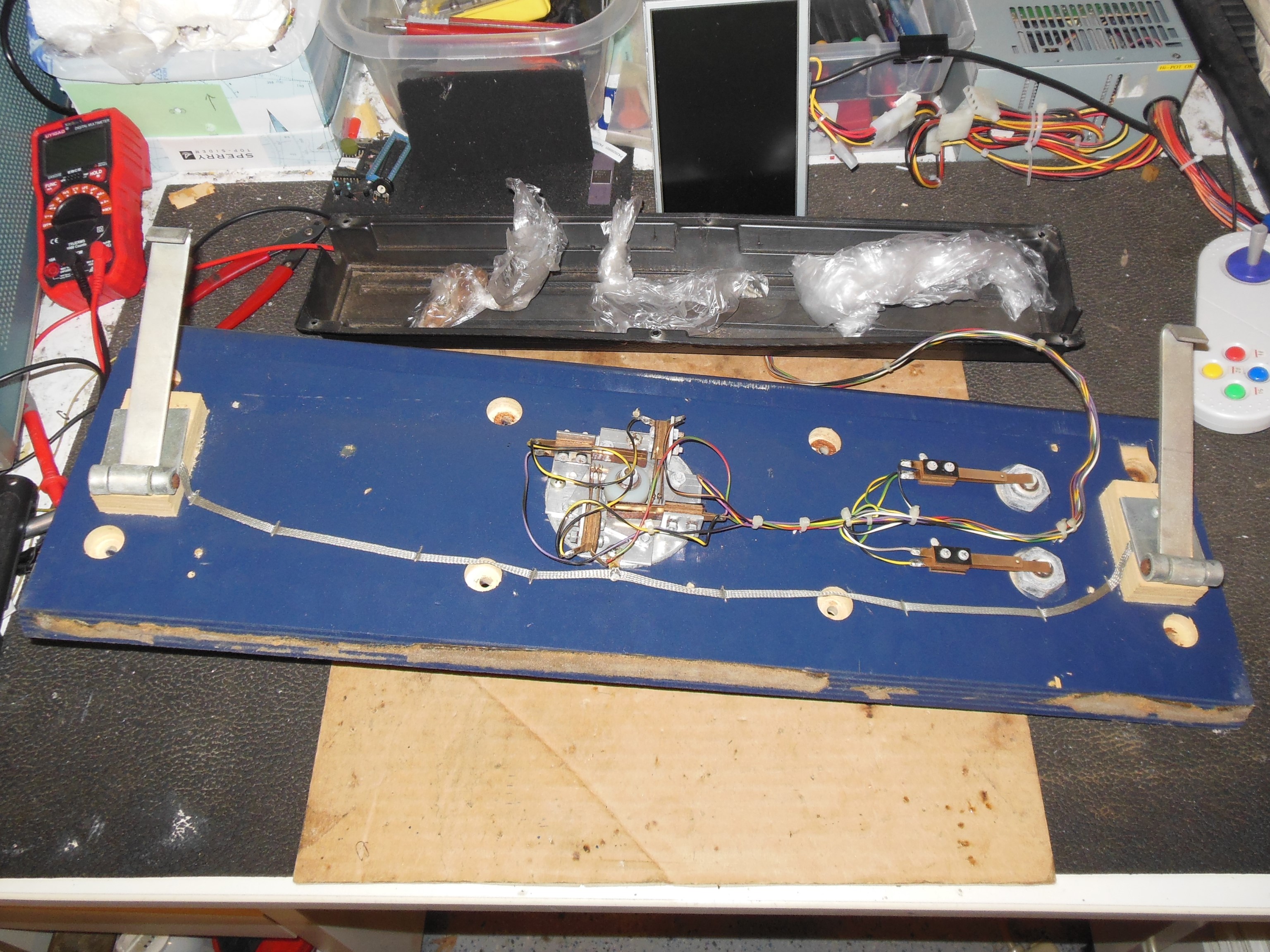
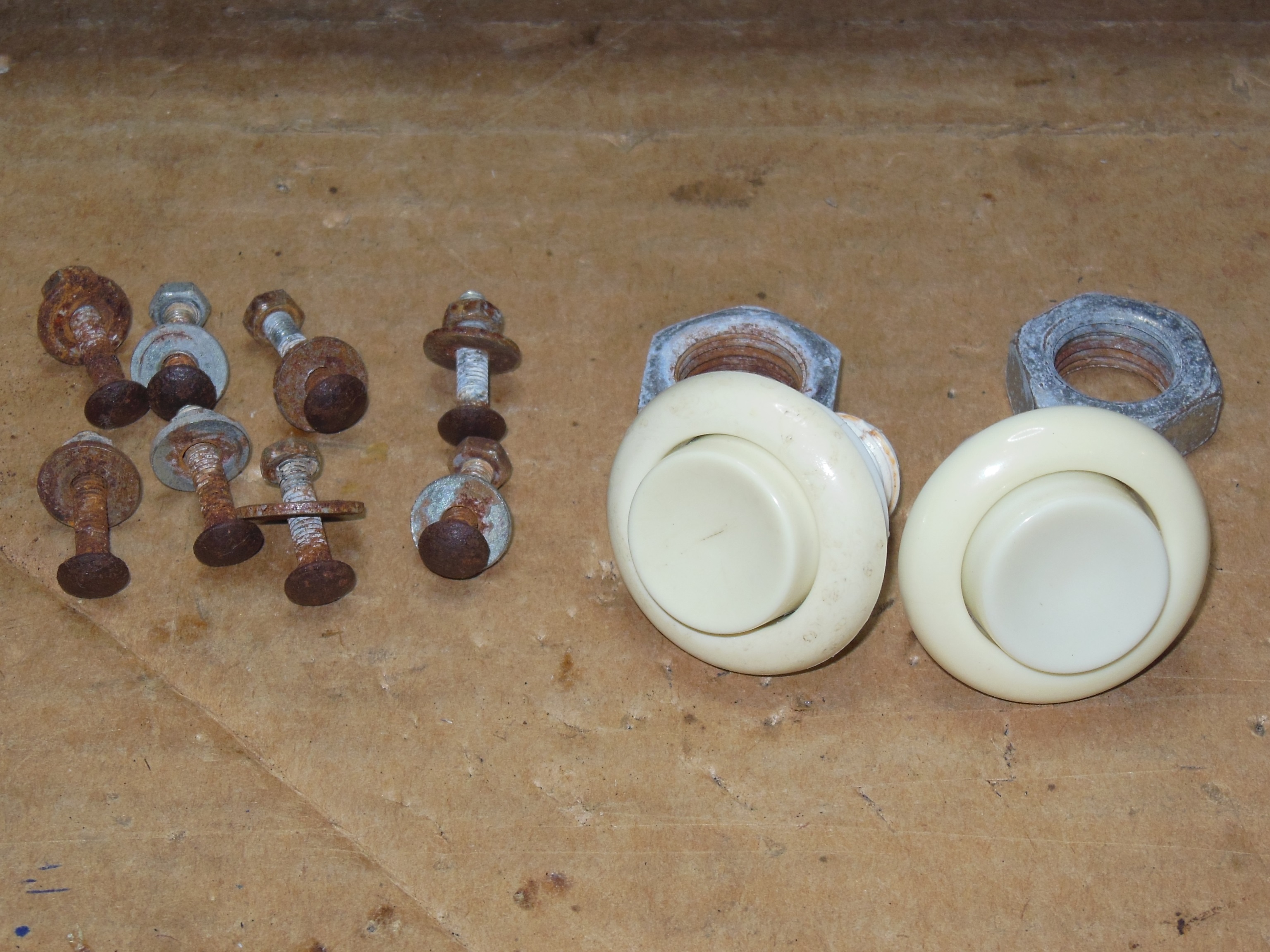
Aside from being dirty and missing the overlay the control panel was complete and original.

|
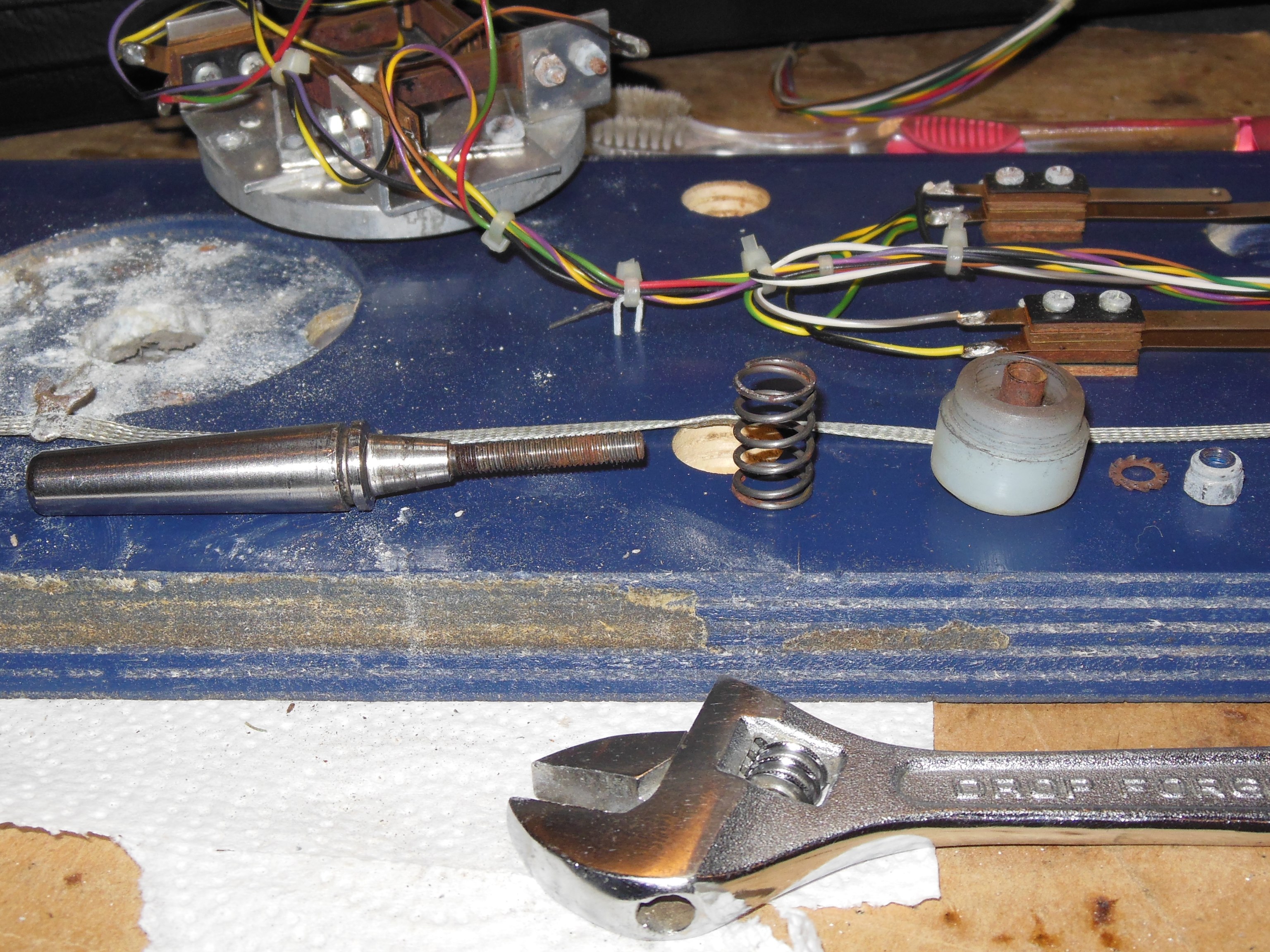
The joystick was disassembled and cleaned. There was a lot of white powdery mold/rust between the joystick frame and panel wood that was cleaned up. The joystick spring was in good condition.
|
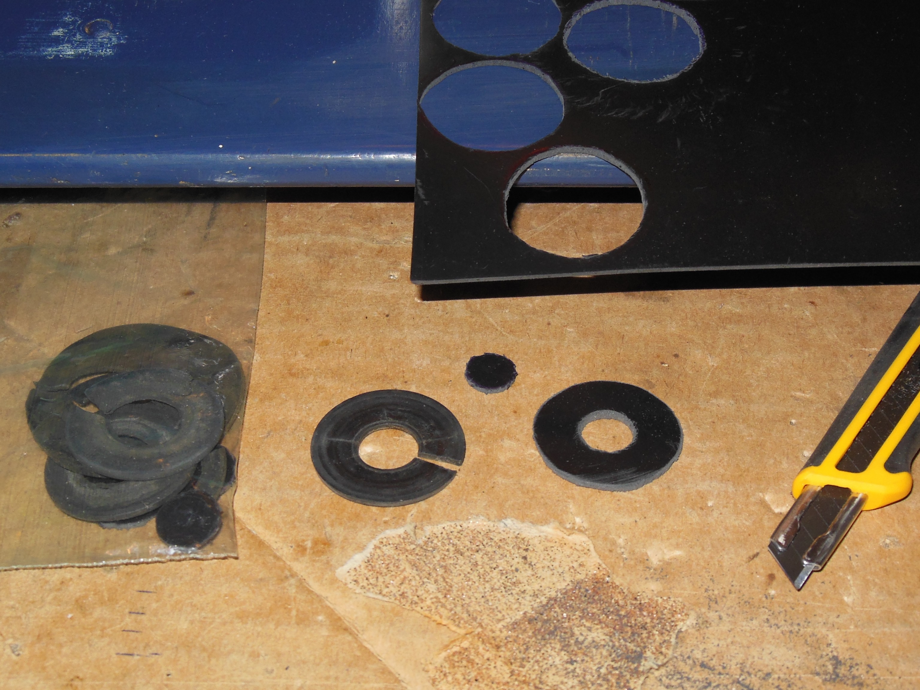
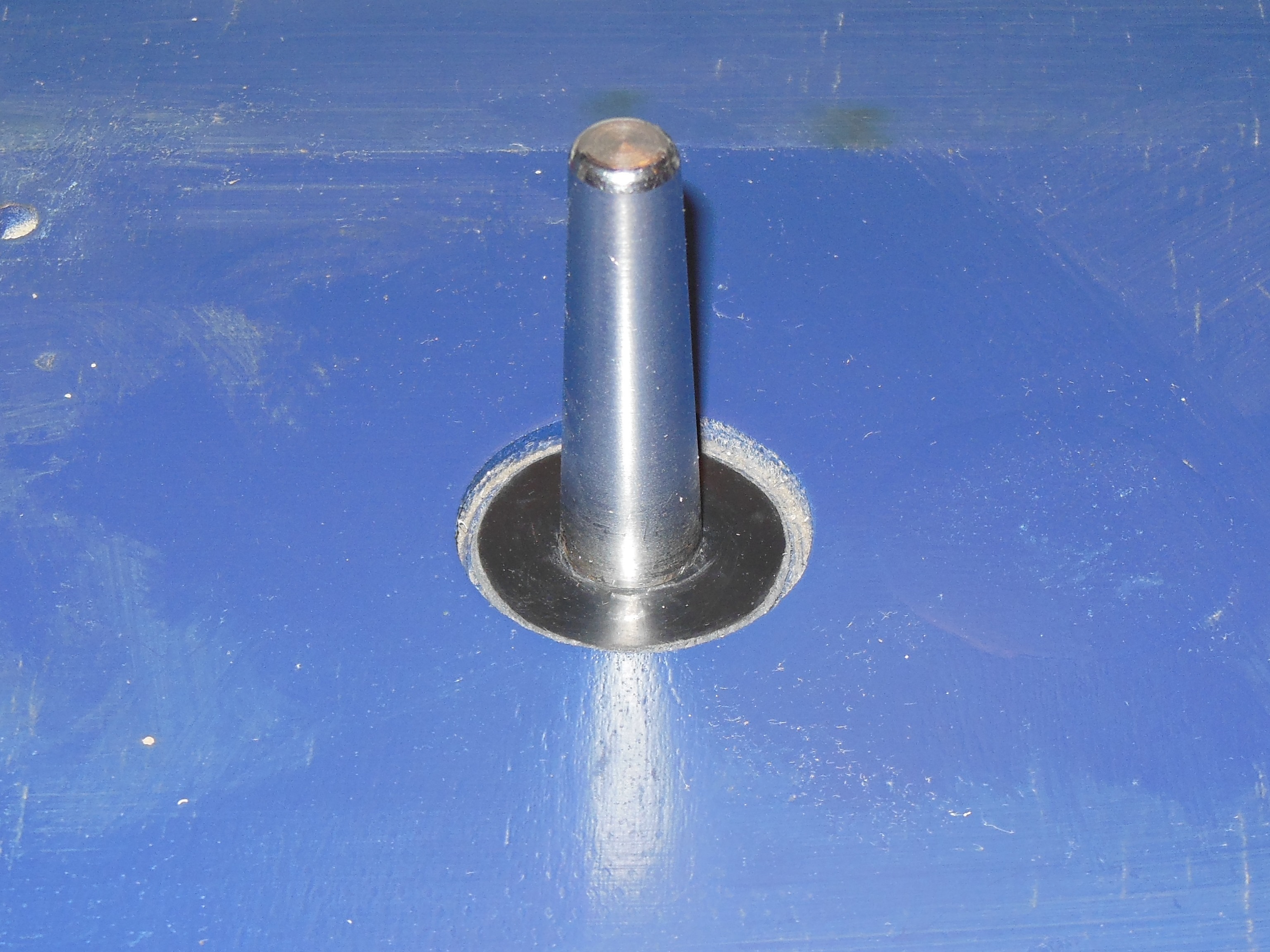
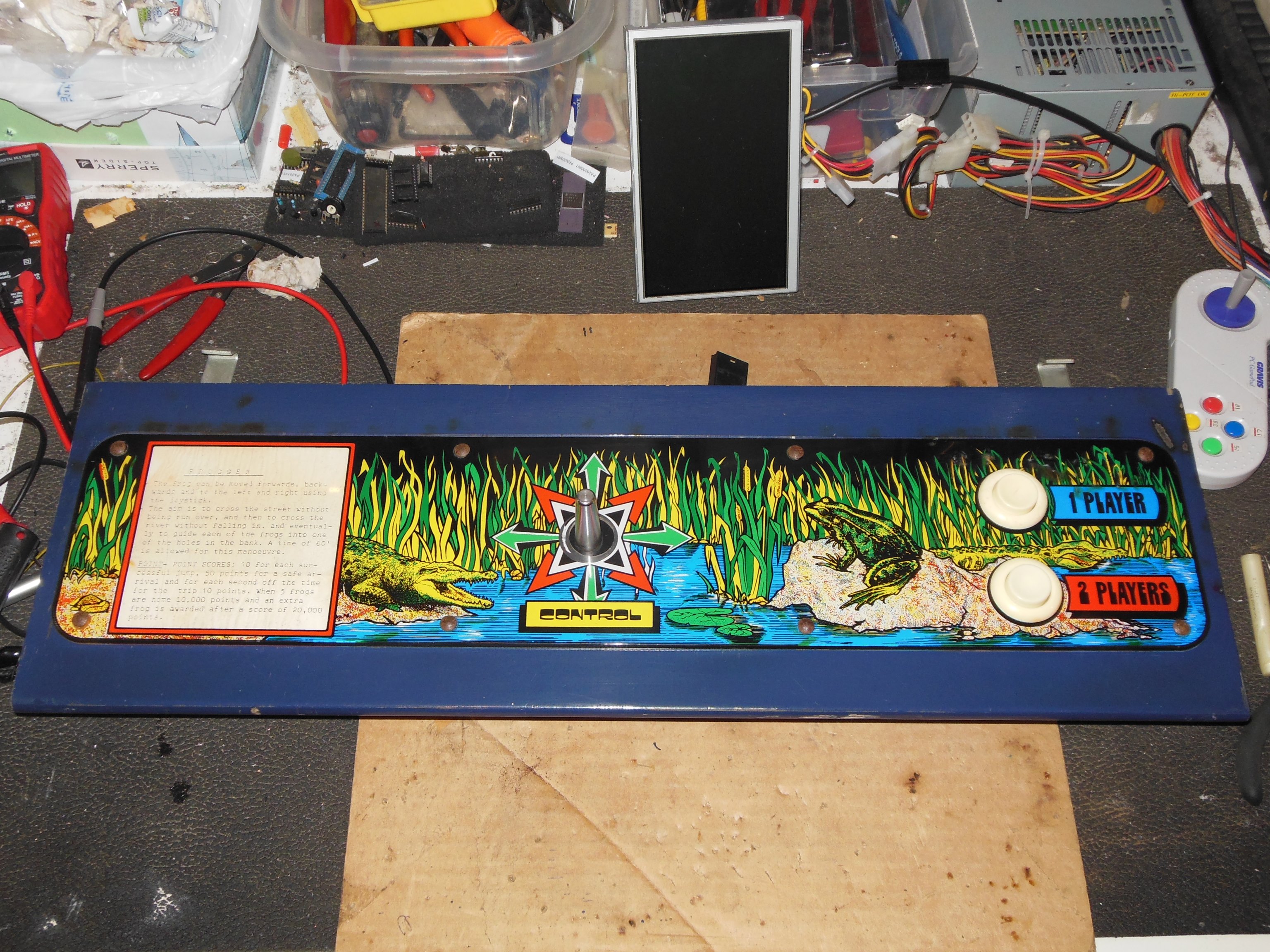
A reproduction shaft dust cover was made and fitted to the joystick.

|
The two buttons were removed, disassembled and cleaned. Finally the overlay was fitted and the control panel fully assembled.
|
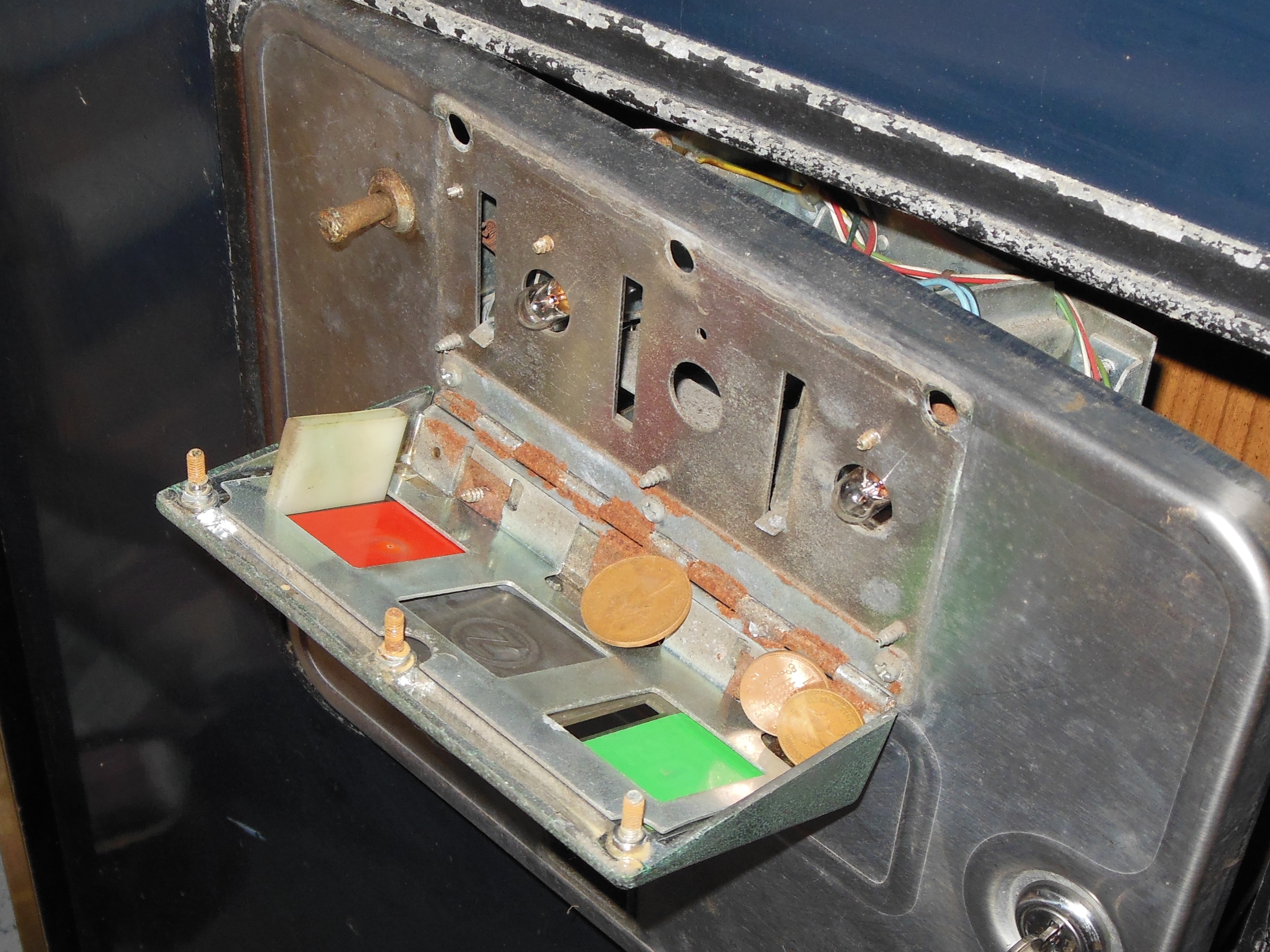
The centre slot "Z" blanking plate was flipped around to face out correctly that also found a collection of trapped coins, likely as a result of the missing guide on the right slot. Both coin bulbs were replaced and a credit button was fitted.
|
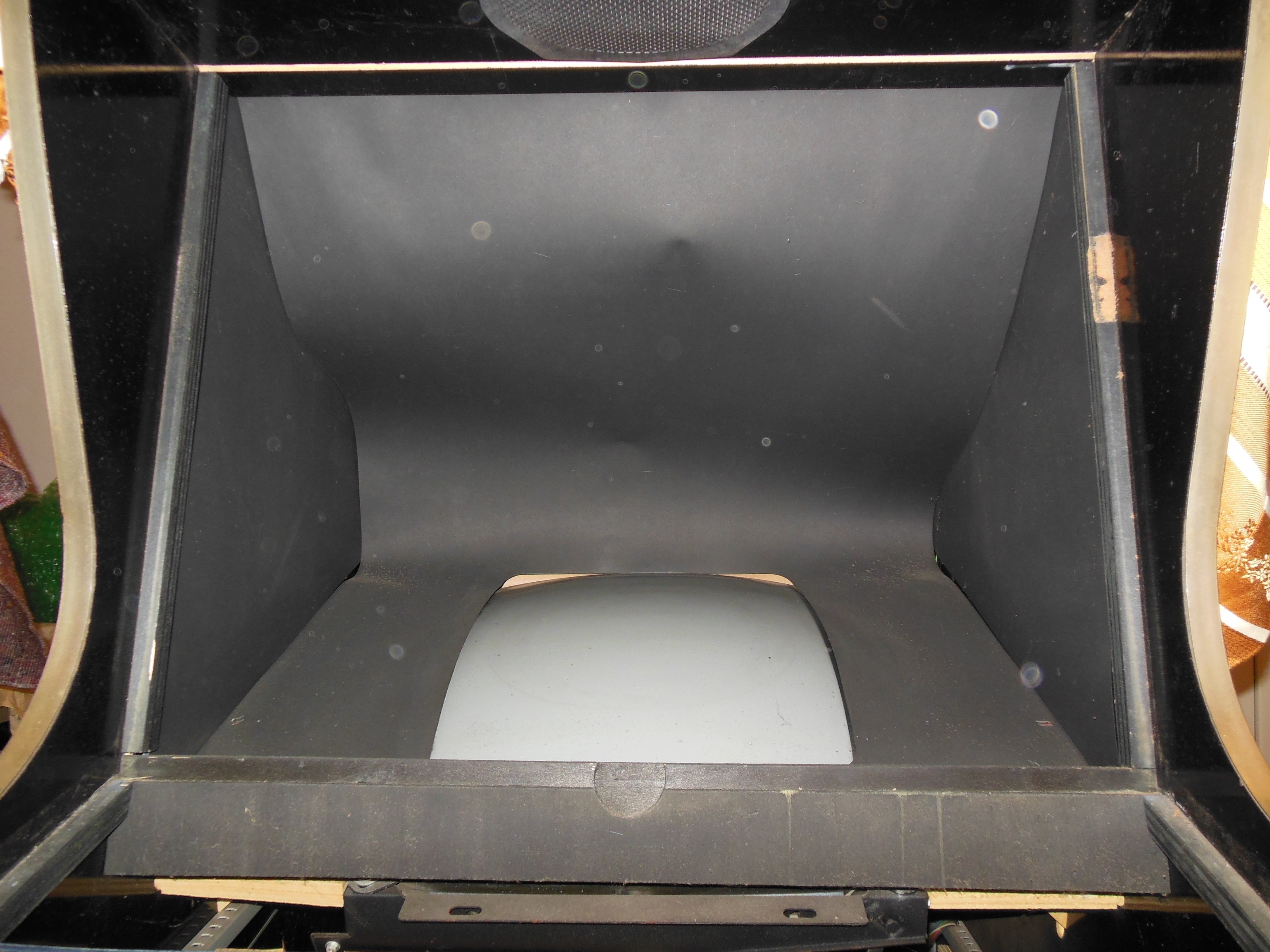
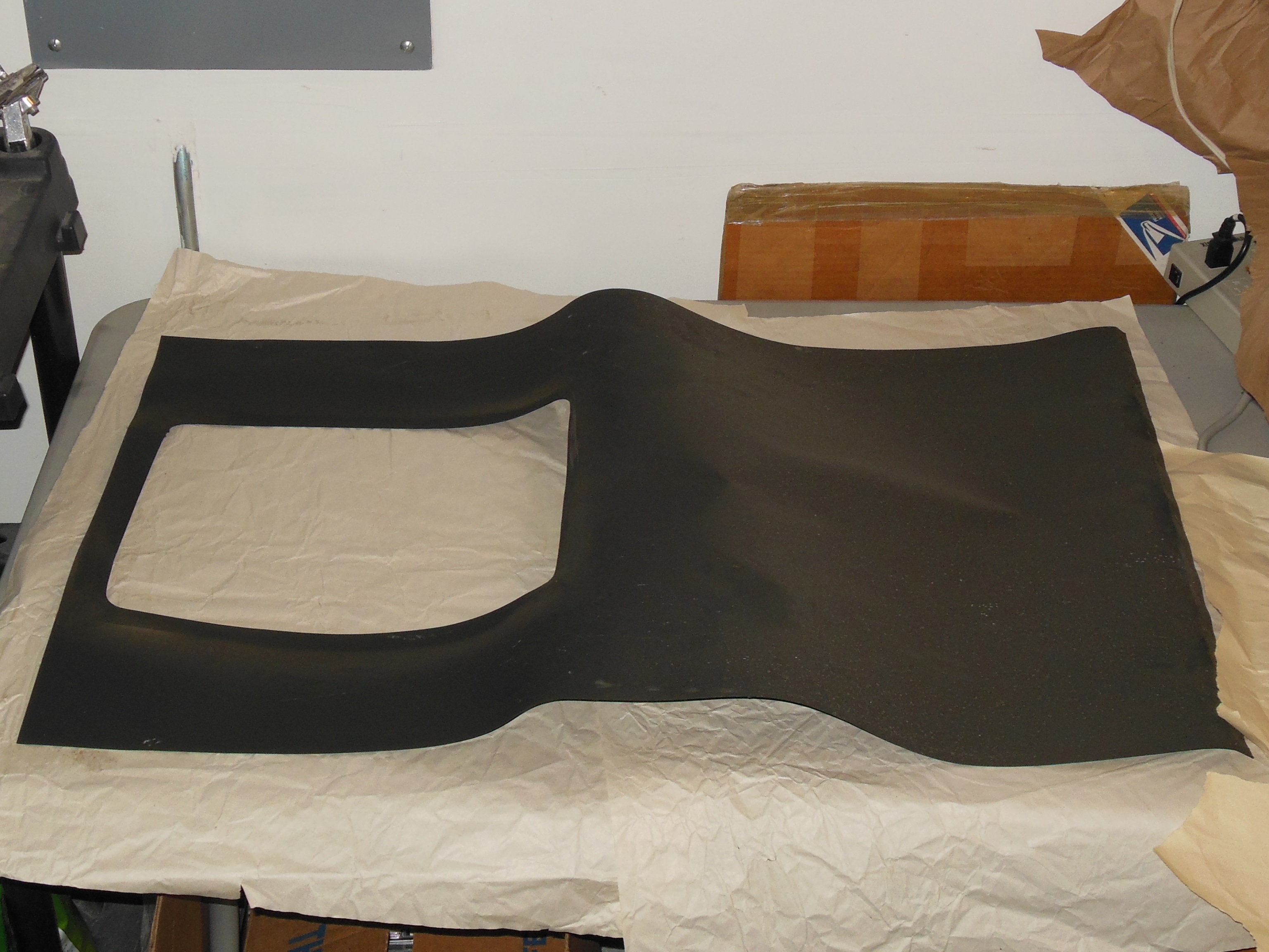
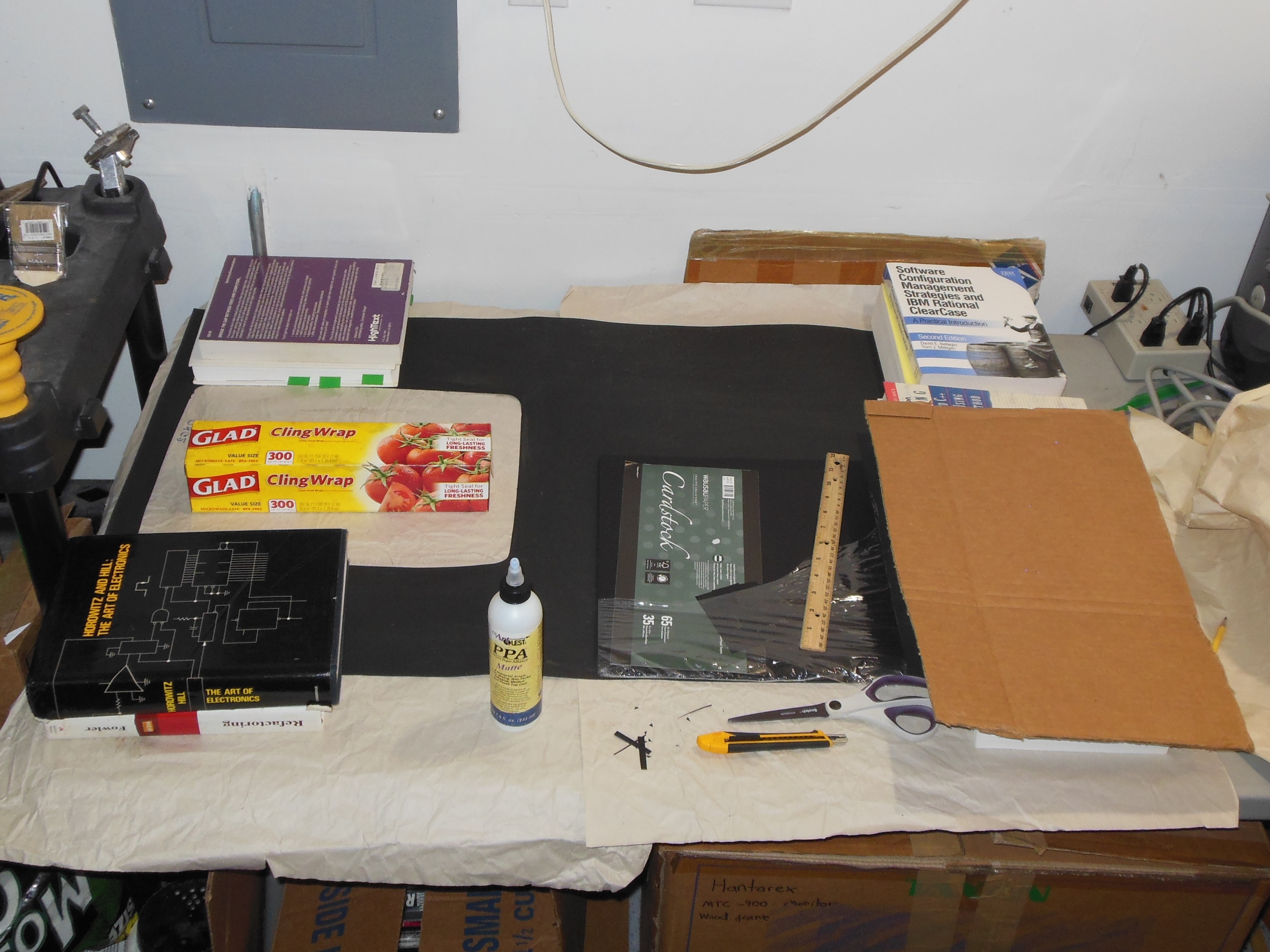
A thin plain black cardboard surround had been used in this cabinet that had collapsed and creased along the top.
|
After a wipe down with a damp cloth to remove the surface dust the surround was set to flatten.
|
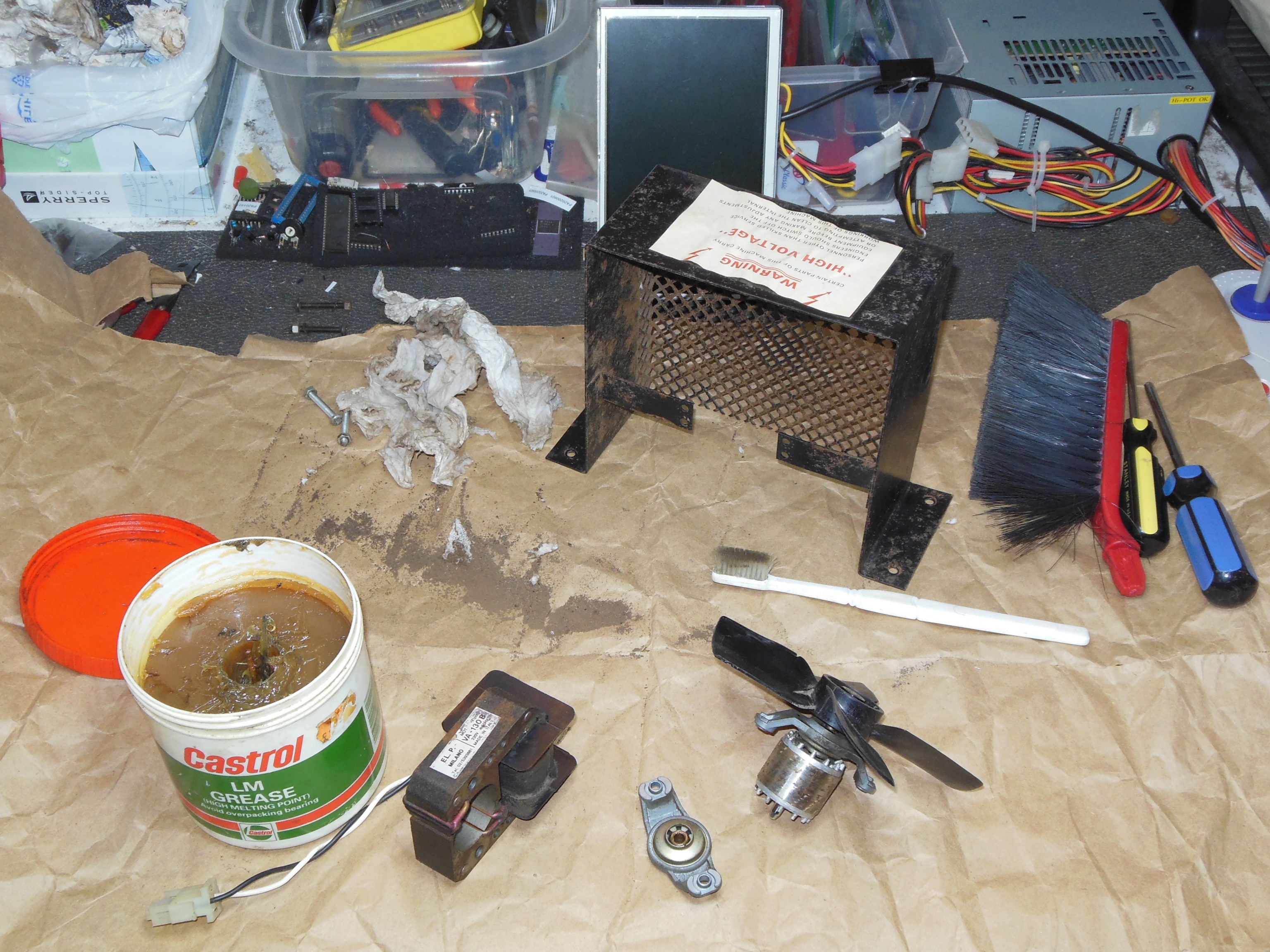
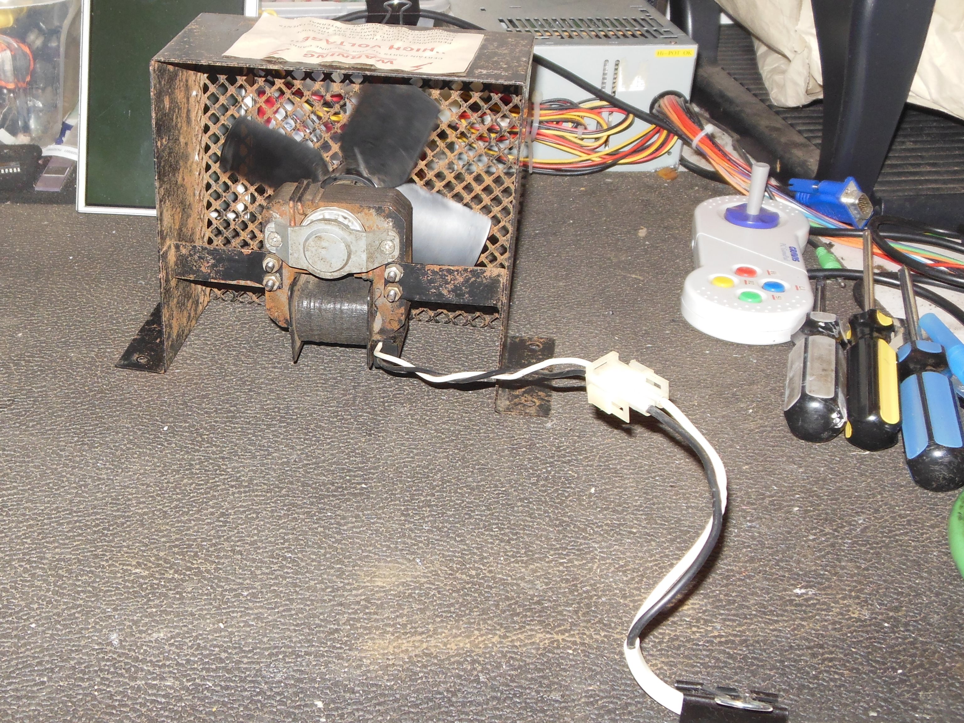
The cabinet fan was removed, disassembled, cleaned & greased.
|
Even after cleaning & greasing the fan was rattling noisily during bench testing.
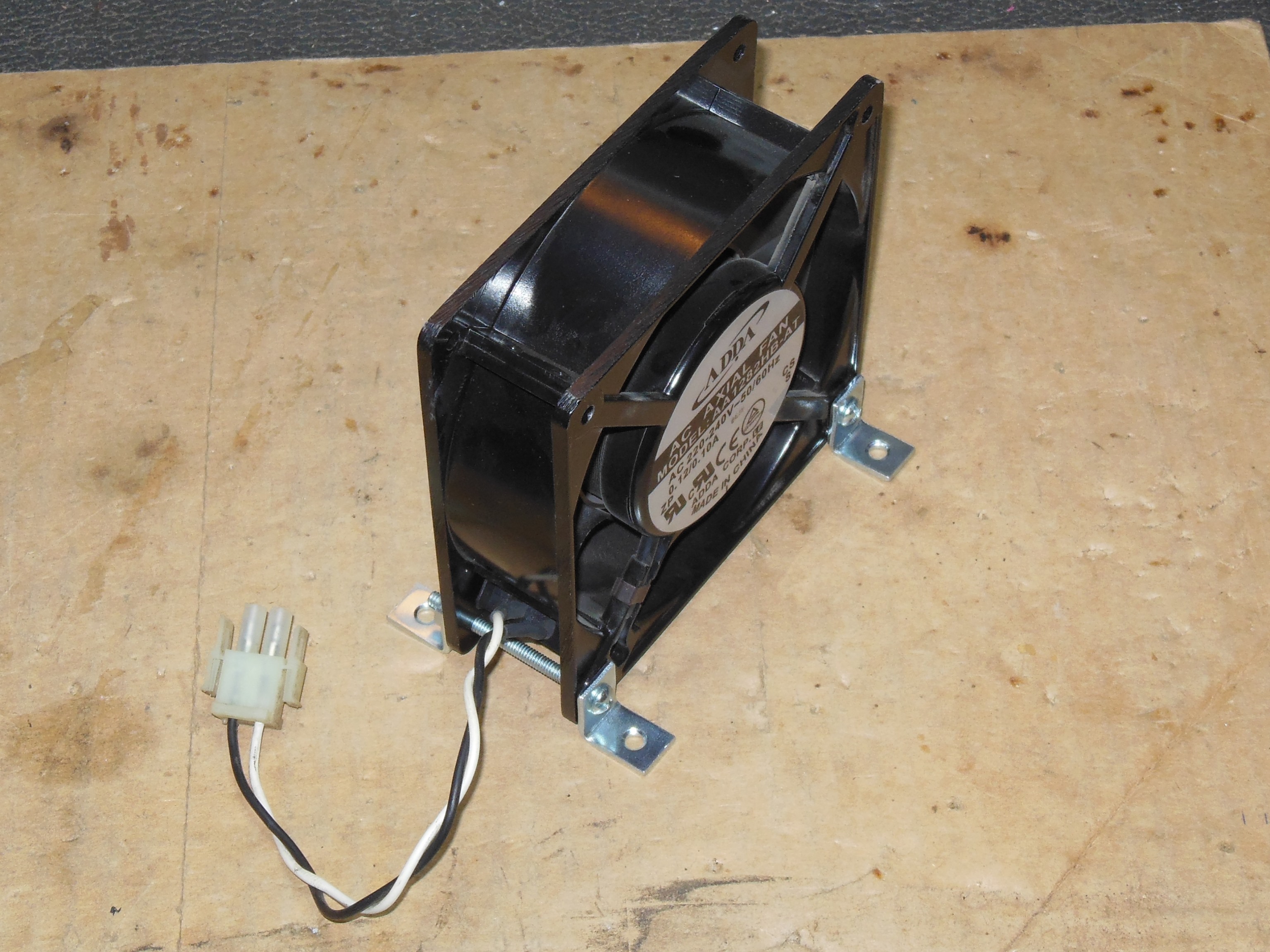
The lower power fans often still run OK but these later higher power ones, El. P. VA-130 B, are often worn out. A replacement fan assembly was built using an ADDA AA1282HB-AT and bench tested.

|
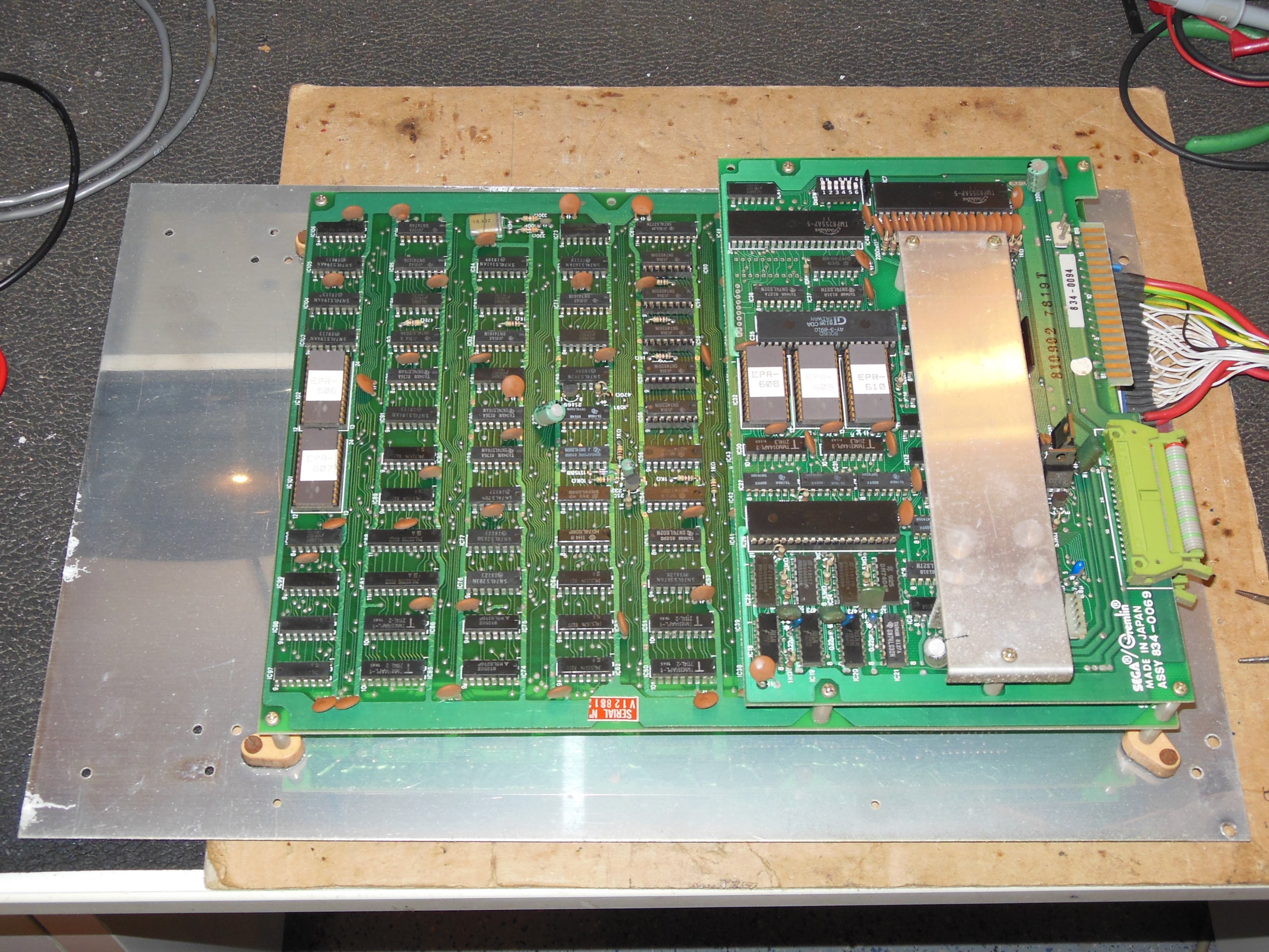
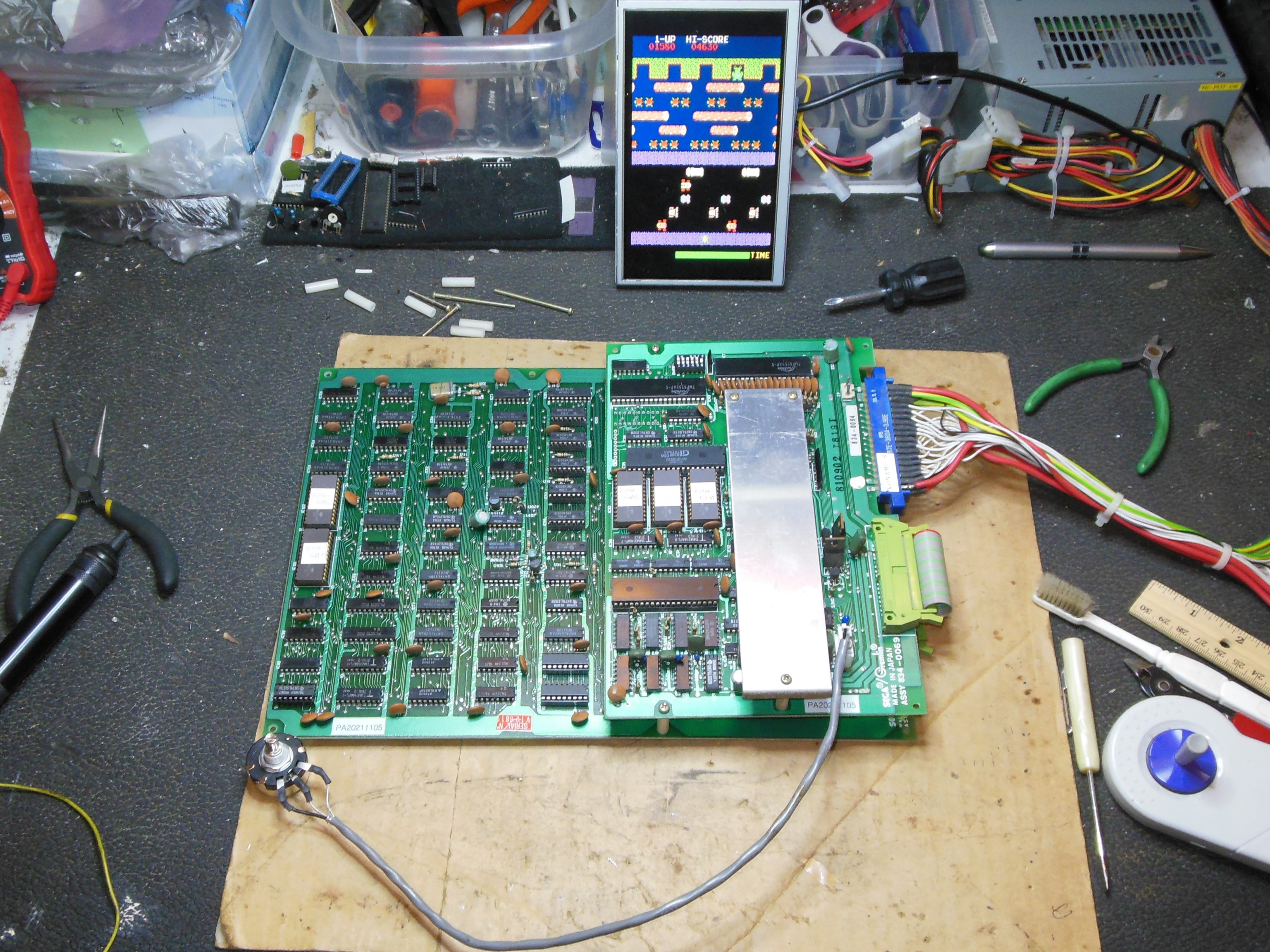
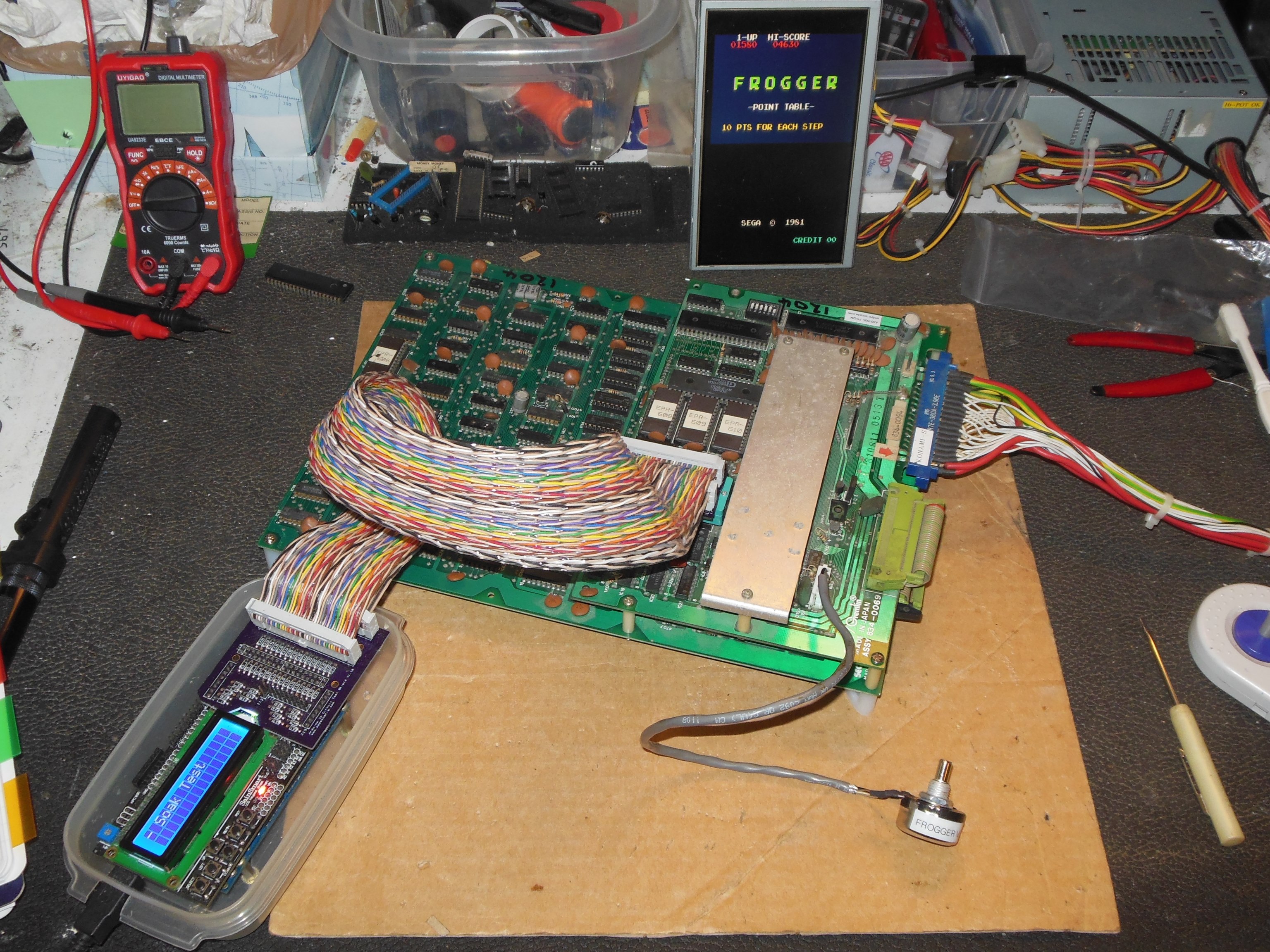
Andy at Andys Arcade sent a spare Frogger PCB to use as the show backup PCB since I had no spare original Konami-style ones. There was a small graphics fault of pixel sparkles on the sprites to fix.
Suspecting the sparkle to be a marginal signal somewhere I started out running a finger down IC pins in the character section and observing if the sparkles got better or worse as a result. This quickly found visual impact on IC 91,IC 104,IC 103 (LS194). Using a scope lead also caused a visual impact that isolated IC 103 pin 11 that was the 6 MHz clock. The 6 MHz clock originated from IC 73 (LS368) pin 3 and a load on input pin 2 did not cause any change in the sparkle, suggesting that the 6 MHz signal itself was impacting. On the sprite buffer RAM the 6 MHz clock was inverted and used to drive the WE line. Using a video probe on the sprite RAMs IC 56-60 found no sparkles on pin 6 D0 and no effect on the sparkles. Moving downstream to the next IC with a 6 MHz clock, IC 24 (LS273) found sparkles on output pin 19 but not present on any input pin. A piggy back of a replacement almost fully cleaned up the sparkles and I suspected IC 24 was bad. Replacing it fixed the sparkles and the game had no further issues.
|
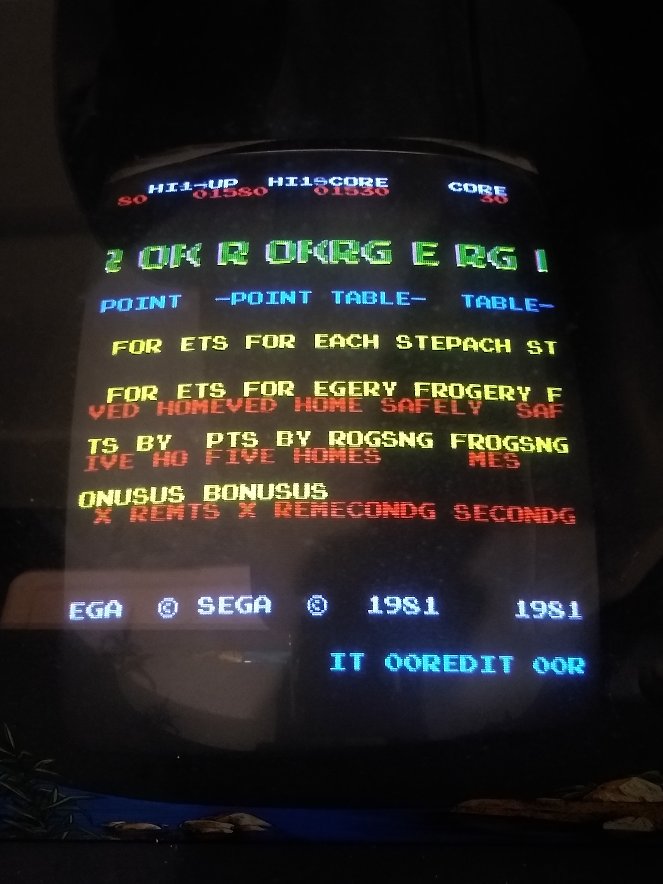
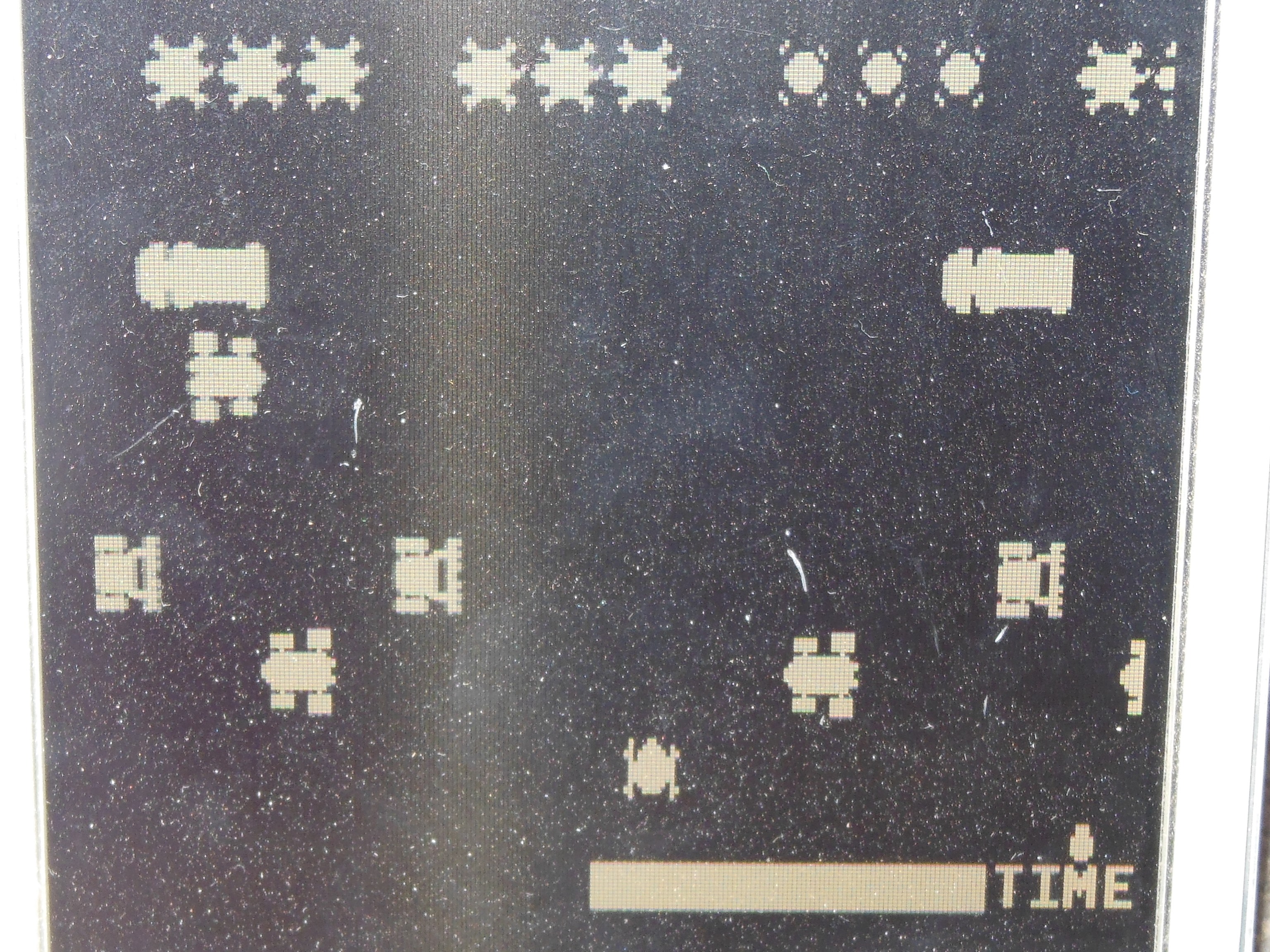
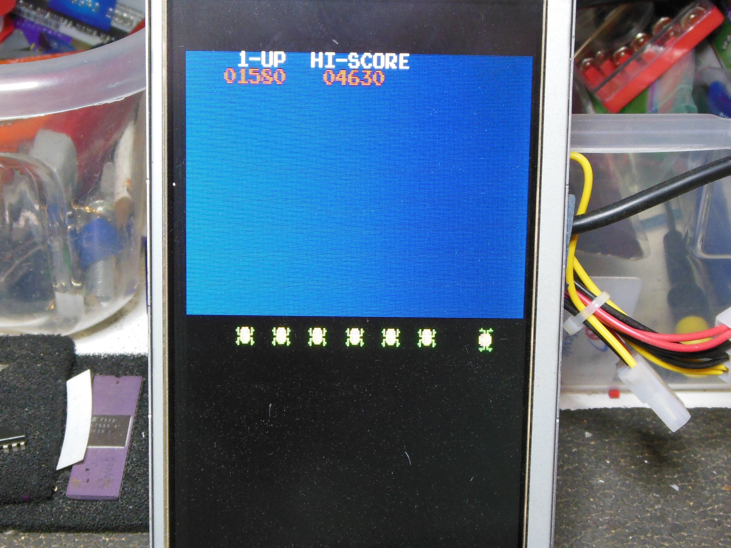
The original cabinet PCB had graphics issues where the picture was split and repeated.
Suspecting a video counters issue I started with the vertical counter IC 95 & 84 (LS164).
Examining the output pins with both scope & video probe:
| Pin | IC 95 | IC 84 |
|---|---|---|
| 11 | OK | OK |
| 12 | OK | OK |
| 13 | OK | OK |
| 14 | OK | OK |
| IC 85 Pin | Signal | State |
|---|---|---|
| 1 | A6 | Aligned with split - H |
| 2 | A5 | Aligned with split - H |
| 3 | A4 | Alternate characters |
| 4 | A3 | Half screen - V |
| 5 | A0 | Quarter screen - V |
| 6 | A1 | Eighth screen - V |
| 7 | A2 | Sixteenth screen - V |
| 15 | A9 | Alternate lines - V |
| 16 | A8 | - no display - |
| 17 | A7 | Half screen - H |

|
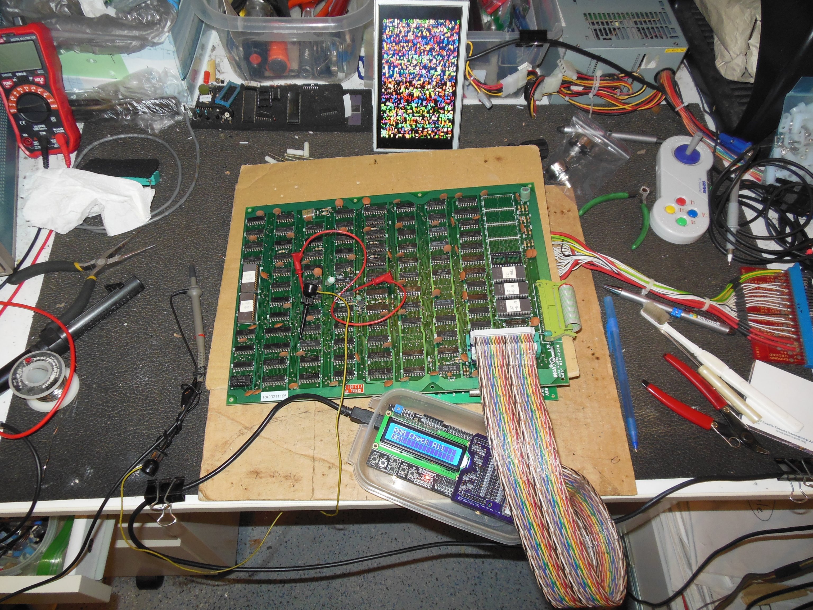
The sprites were still mis-positioned. Checking IC 85 (2114) pin 12 data bus with the video probe found the mis-position visible. It was also visible on IC 86 pin 11. At this point I needed to add support for Frogger to the Arduino ICT in order to check the video RAM.
Testing with the Arduino ICT didn't reveal any issues with ROM, RAM Interrupt or the I/O ports. Unlike the Galaxian platform, the Scramble platform doesn't support read of the object RAM so write/verify of that RAM isn't directly possible. Instead the Arduino ICT was used to "RAM Write All AD" that sets data equal to address and allows the data output to be verified using a scope - the data bus output should look like a binary clock. Checking IC 50 (2114) found the data bus looking as expected. Checking IC 51 (2114) found:

|
|
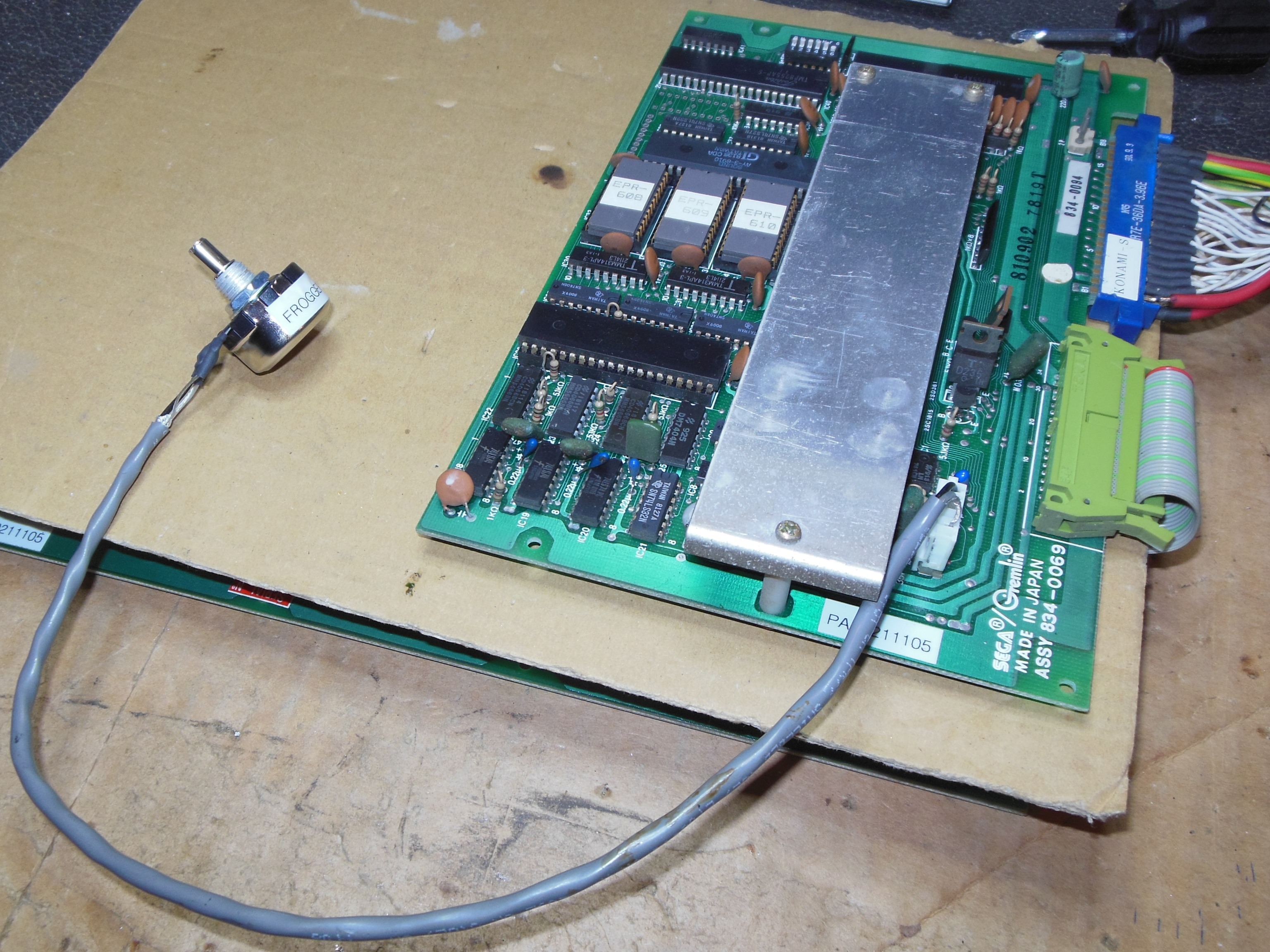
The volume control connector on the PCB I recognized as the same style as the ones used on DECO Tomahawk 777, a JST NH series connector. I didn't have the correct size in stock but was able to cut down a longer one to fit instead. A large 220 Ohm volume pot was ordered from eBay and a short length of 2-core plus ground signal cable connected the two. Neither of the two PCB sets had any sound issues on the bench or in the cabinet.

|
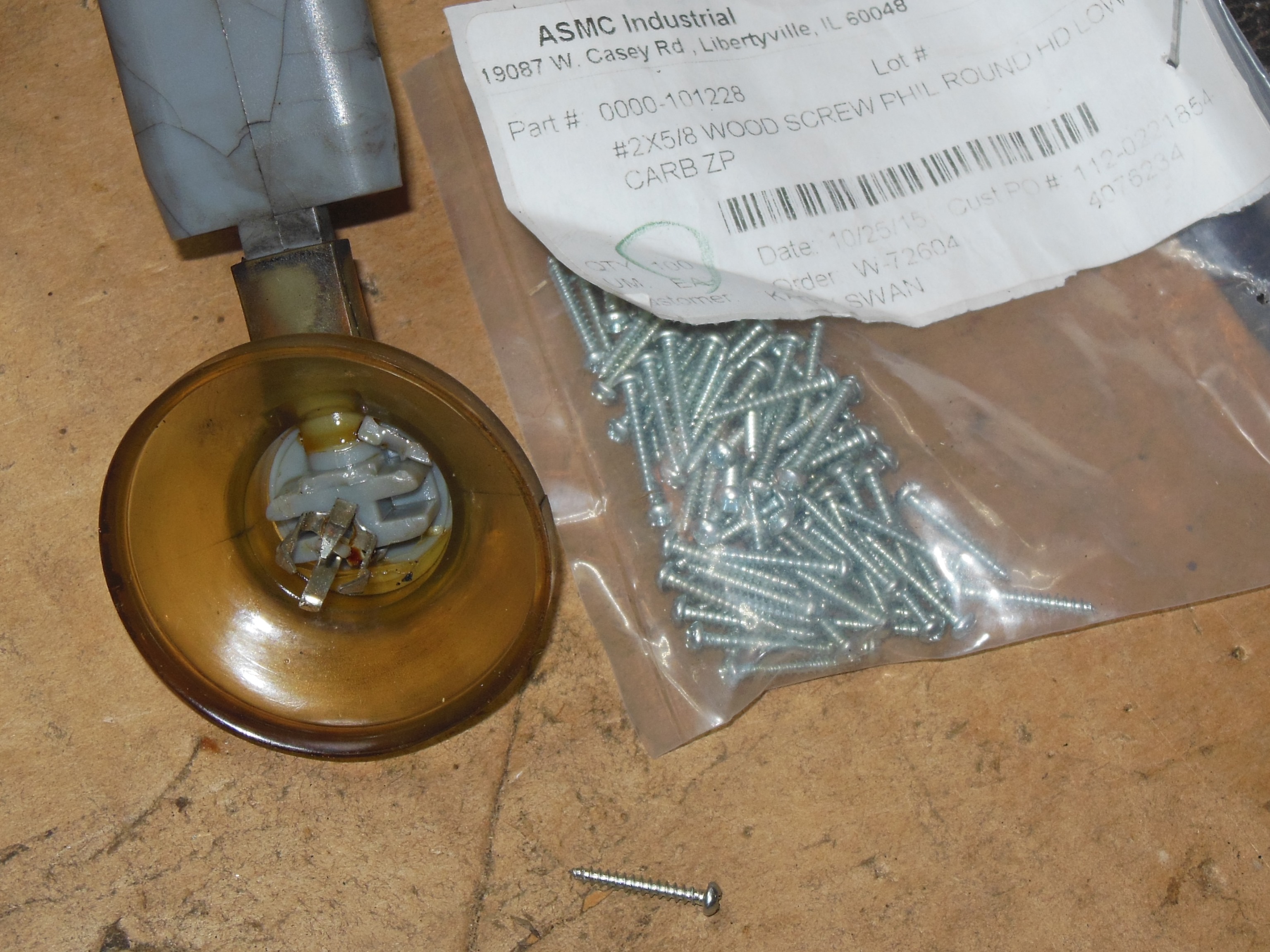
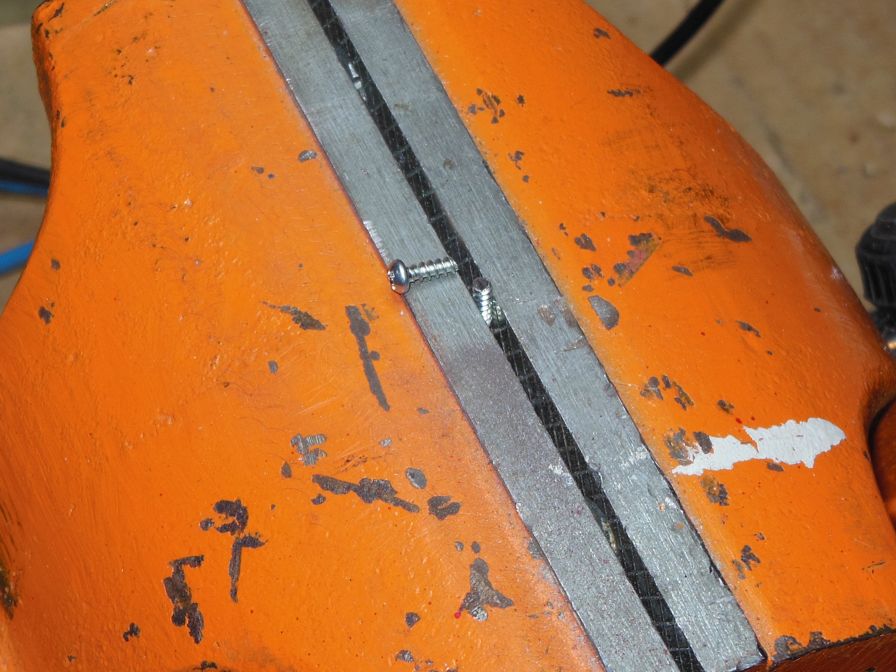
After removing the monitor chassis I discovered the clasp on the HV cup had snapped off. A #2 5/8" wood screw was cut down with a Dremel to secure the clasp in a new 1/16" hole drilled into the centre plastic block.

|
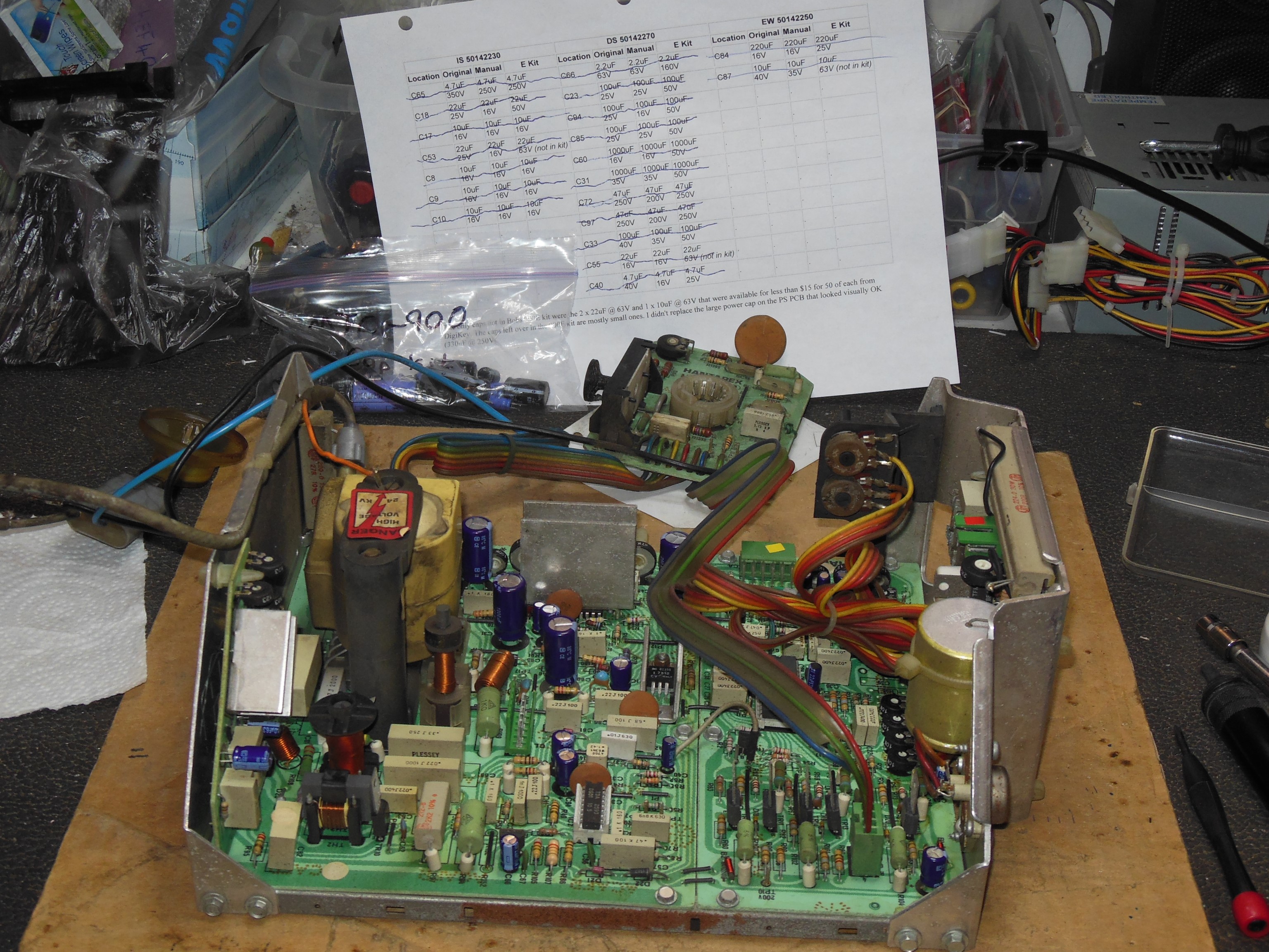
A DIY cap kit was fitted to the Hantarex MTC-900 chassis. The chassis was in good physical condition.
|
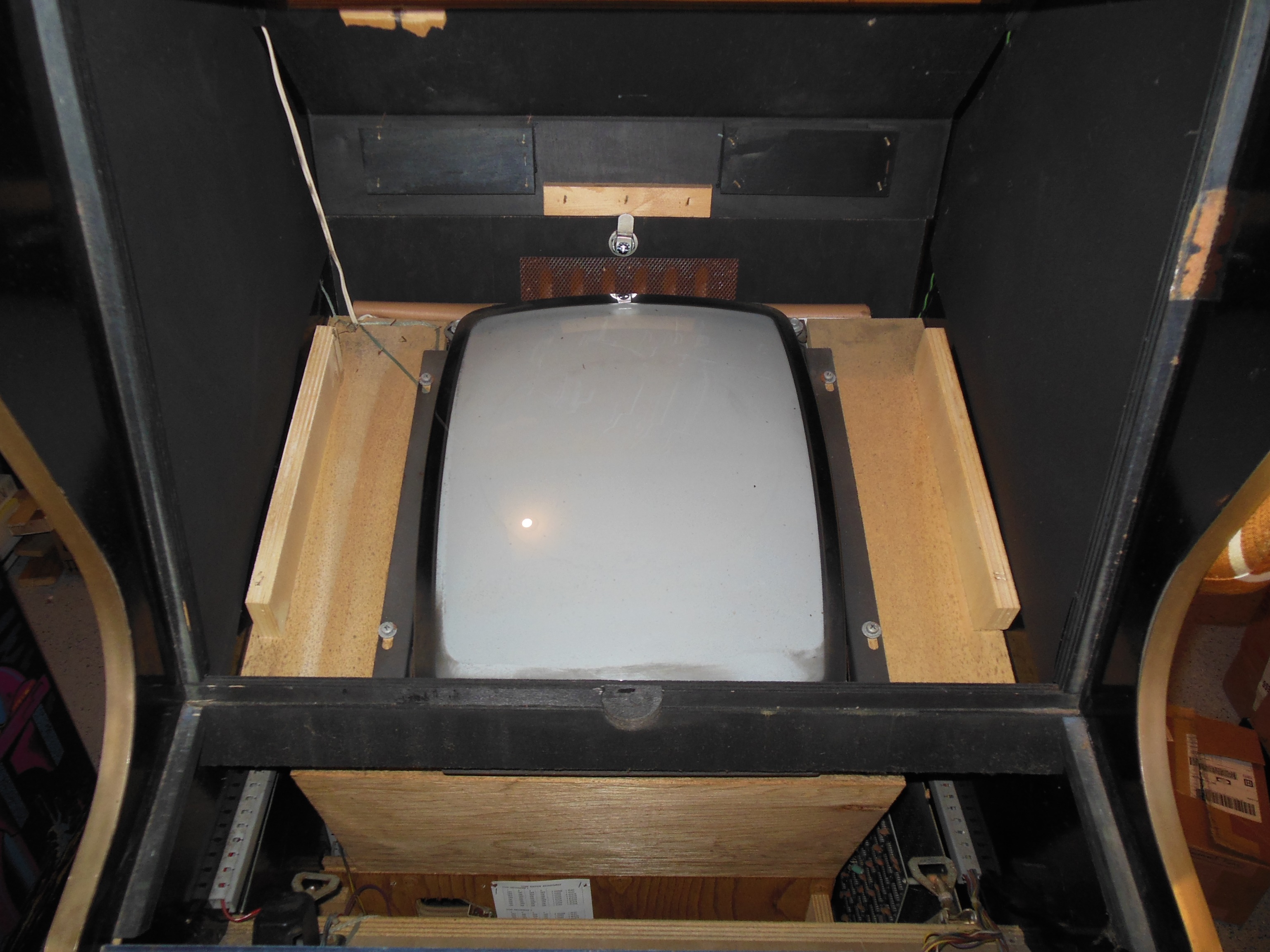
The cabinet was dusted, vacuumed and wiped down with a damp cloth. The CRT & frame was also cleaned.
|
I'm not sure what had happened to the ground braid, but it was very tight and snapped during the attachment of the ground clip. The two ends were too tight to join so a small section of solid core wire was used to add extra length and join the two ends. The chassis ground clip was then attached.

|
All the components were installed back into the cabinet.


|
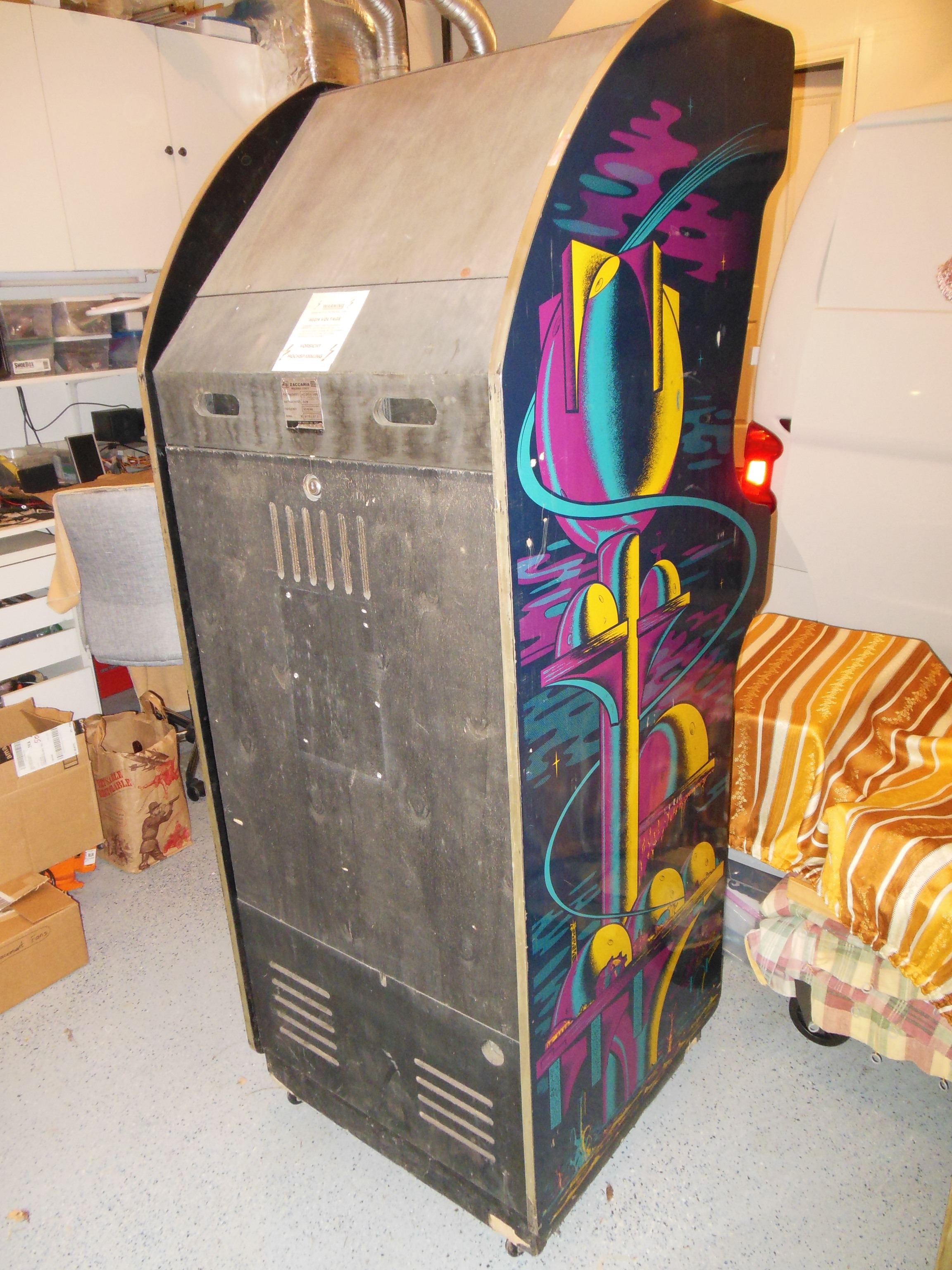
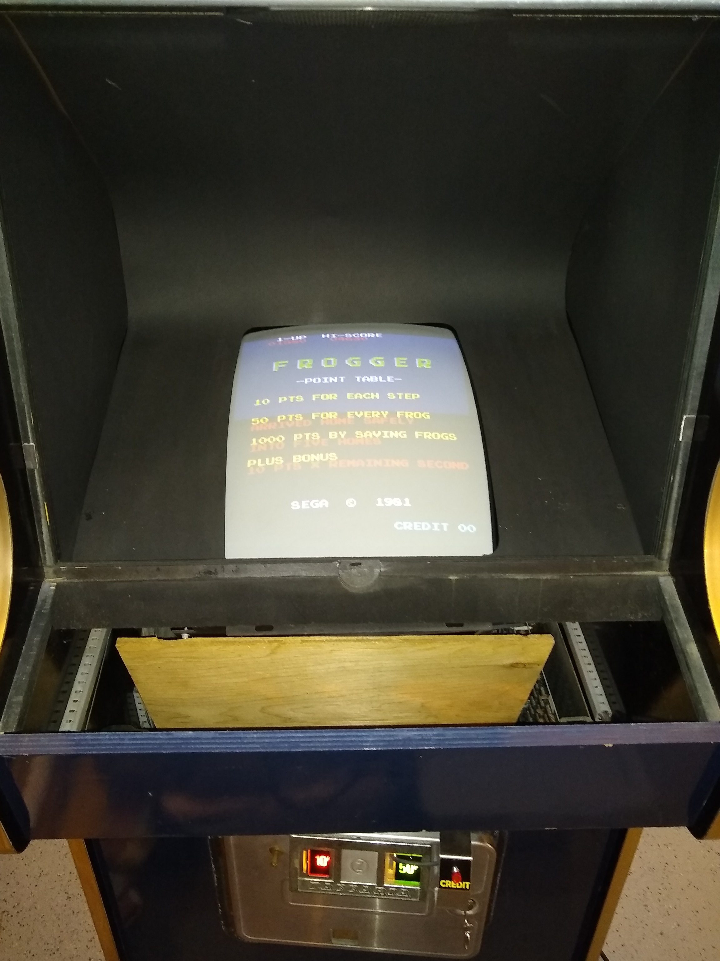
The plain black monitor surround wasn't as thick as the printed surrounds and even with top edge reinforcement was flimsy. Whilst checking the cabinet I noticed that the side walls still had printed artwork cards underneath - plain black card had been stapled over the star field card.
|
Despite the flimsy card the reinforcements were able to hold up the cavity but it remains to be seen if it will stay that way over time.
|
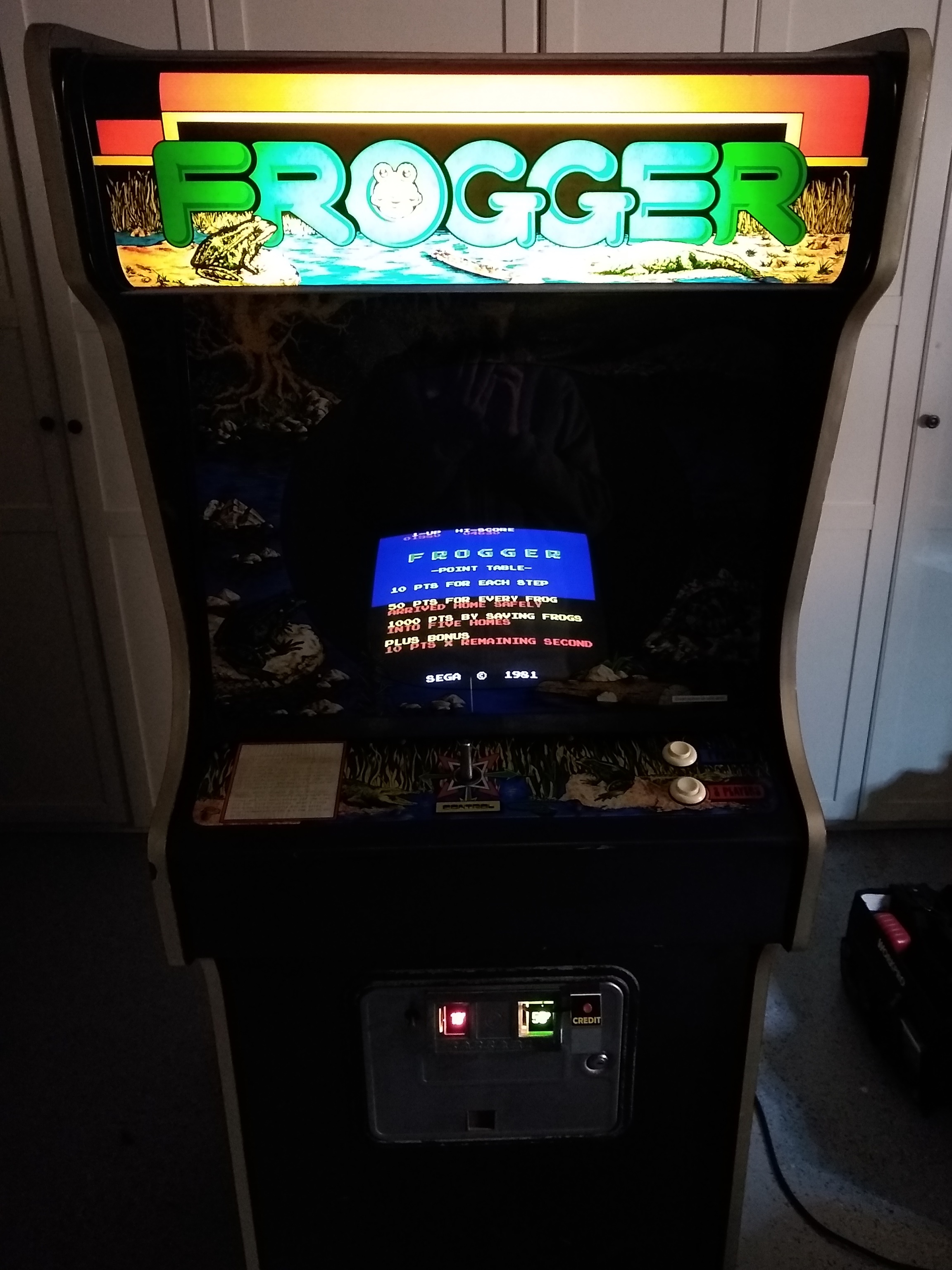
A final power on test encountered no issues and after a few hours of run time the monitor was adjusted. The vertical height was also increased a little.

|
A final power on test encountered no issues and after a few hours of run time the monitor was adjusted.
|
|
Scanned in the Frogger monitor glass.
300 DPI Frogger monitor glass scan (33.0MB).
|
Testing the spare PCB on the bench found that it had no game sounds but there was speaker his and the volume control appeared to be working. Using the Hustler sound support on the Arduino ICT (same sound PCB as Frogger) passed IC 30 (2114) but "E:31 4001 00 80" failure on IC 31 (2114). "AY Check" passed OK but the AY IC 35 channel A filter 2 test had no sound output. Manually checking the ROM CRCs found them both correctly matching MAME: