

|
|
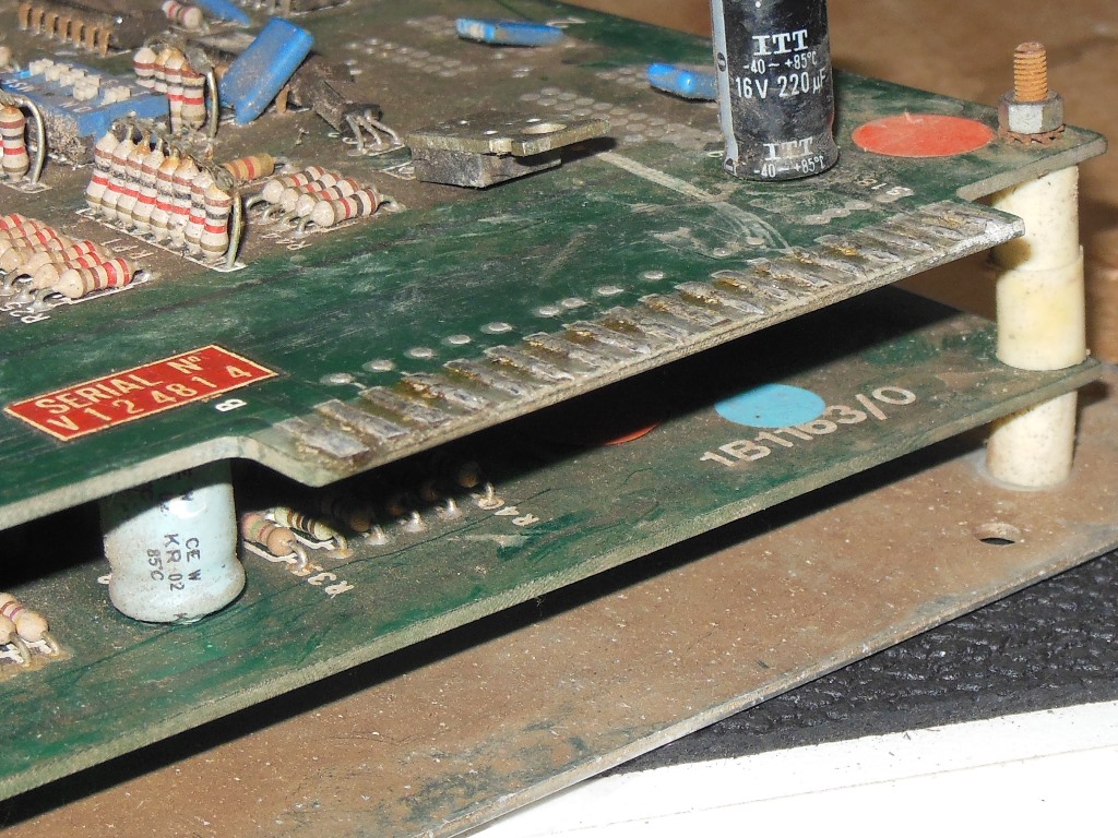
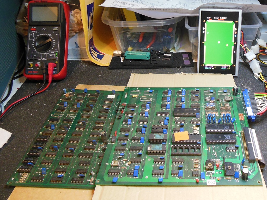
As part of a Zaccaria Scramble restoration I'd rounded up all my Zaccaria Scramble PCB sets with a view to having two working sets (one in the cab and one spare). One of the sets I found had been converted to Hustler and since I had already managed to get to two working Scramble sets I decided to leave it as is and keep it as a spare board for my Hustler. Interestingly, the board set mounting plate was labeled Super Cobra but there was no evidence the PCB set had ever been converted to Super Cobra.
|
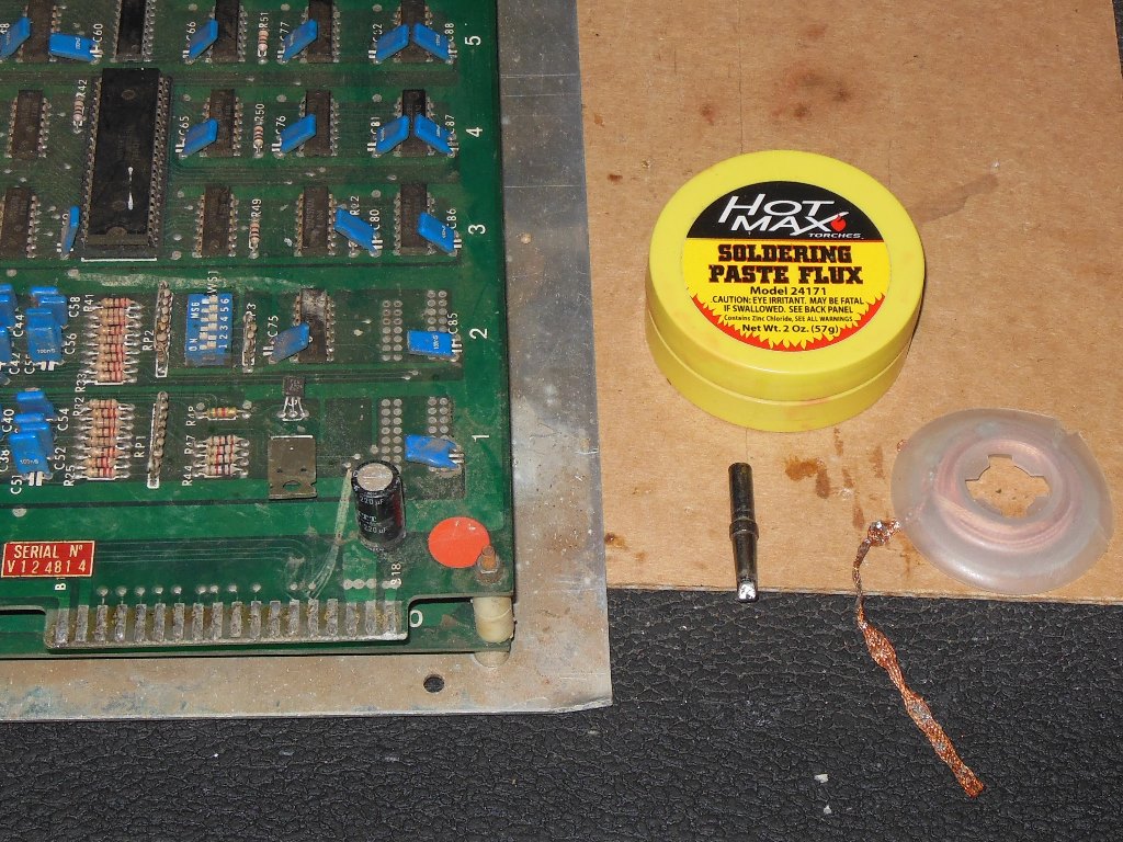
The edge connector had been previously directly soldered and blobs of solder still remained that would damage the edge connector if left as it was. A large flat edge soldering tip and soldering braid was used to "mop up" the excess solder to restore the edge fingers.

|
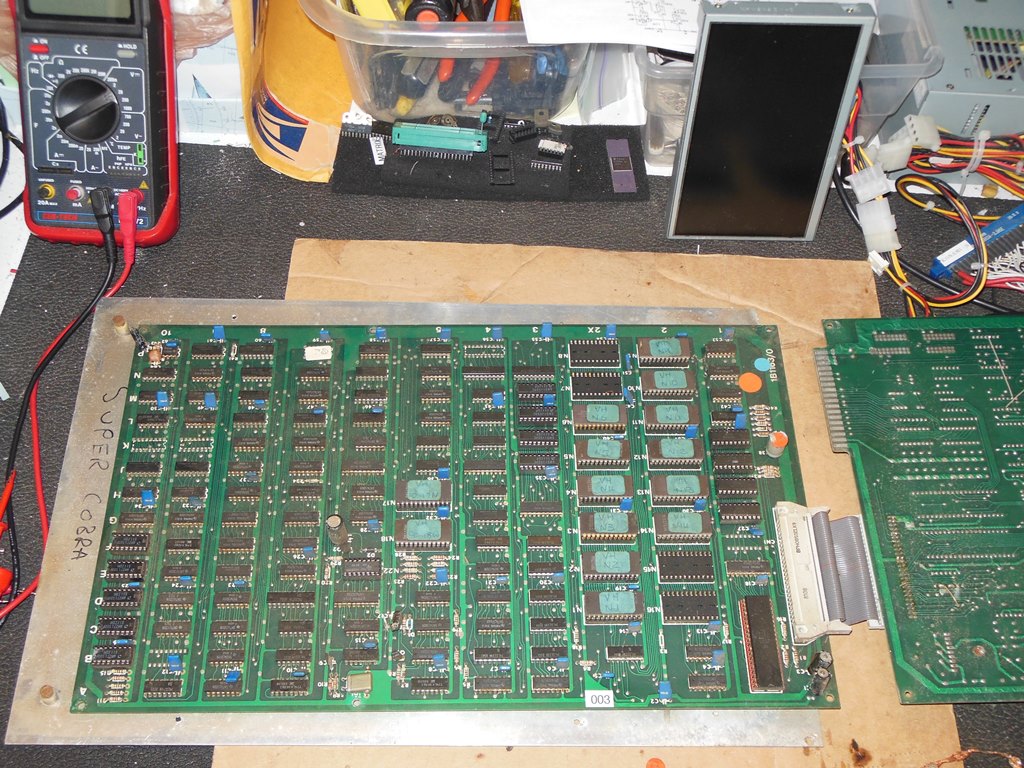
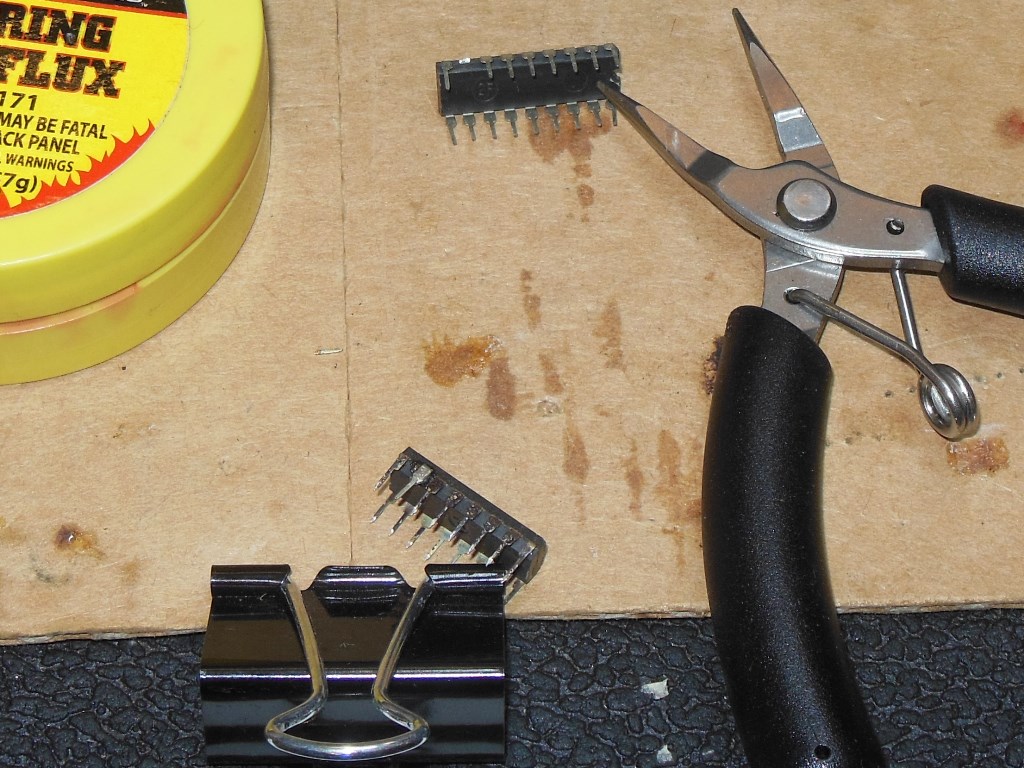
The conversion was fairly neat. On the main board there were a couple of cuts and straps to go with the ROM swap. The Hustler ROMs had been split into 2708s to match the Zaccaria PCB set. The sound PCB had one of the AY-3-8910's removed and a few more cuts and straps. For future reference I dumped the conversion ROM set and added the game to the Arduino ICT.
Zaccaria Scramble Video Hustler Conversion ROM Set (13KB).
|
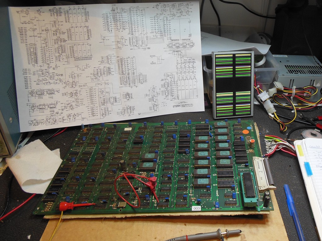
First power on yielded a static image with no boot and no video sync. The reset capacitor, 10uF @ 40V was at least broken but the game still didn't boot after fixing it. Pursuing the lack of video sync, starting with the video counters found IC 6M (LS161) outputs running OK. IC 6L (LS161) outputs were all idle. Pins 10 & 7 LD looked OK and I suspected IC 6L was bad. Replacing 6L (LS161) fixed the video sync and the game booted up.
|
The colour PROM pins looked black and corroded. On removal, one pin snapped off that required a pin graft to fix - using a pin removed from a scrap IC soldered onto the sanded clean stub of the missing pin.
|
The board didn't stay running for long. It started out failing to boot and then lost graphics to coloured bars on a split screen. Starting with the graphics problem, ROM IC 5H (2716) had pins 6, 7 & 8 (E2, E1, E0) all idle. IC 6J (LS273) pin 1 VBLANK was running, pin 2 output was idle, pin 3 input was running. IC 10N (LS139) pin 1 LD was running, pin 2 2H was running, pin 3 4H was idle and pin 4 VPL was idle. Tracking back to the video counters found IC 6M (LS161) pin 13 idle. I suspected IC 6M (LS161) was bad and replacing it brought back the graphics but the game still didn't boot.
Moving on to the no boot, the Arduino ICT flagged ROM byte errors:
2XC 0008 77 af
2P 26d7edbd
2XE 0808 26 85
2M 0c08 16 86
2XF c008 c8 af
The address of the failing byte was mostly of the form xx08 suggesting that address bit
A3 was stuck. Probing with a scope found that IC 2C (LS367) pin 12 input was OK but
pin 11 output was stuck low. Since this was the address bus there were a lot of IC's
that could have been the cause (pulling down the output). Forcing IC 2C pin 11 high
with a strap to +5V caused IC 2C to get warm. Replacing IC 2C (LS367) brought the game
back to life.
|
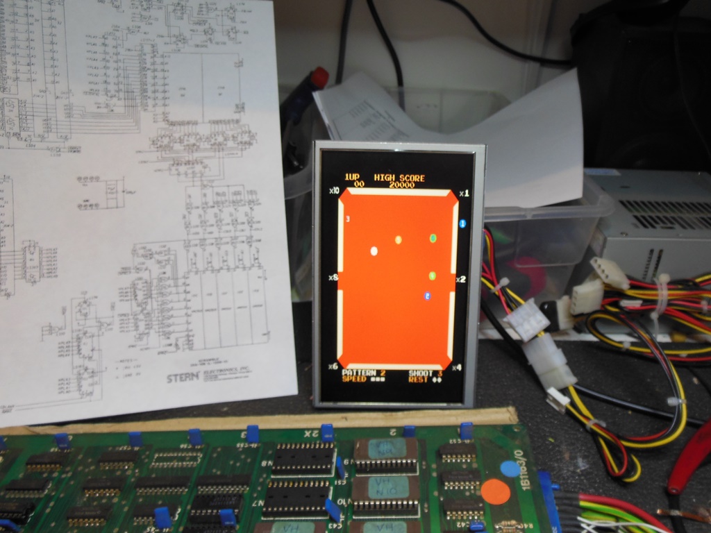
After a few hours of soak testing on the bench the colours went bad - the green baize had become red baize. Starting with the three colour selectors COL0, COL1, COL2 at IC 8C pins 11, 3, 8 found all three with different scope signals and nothing conclusive. The scope probe on IC 9C (LS20) pin 6 caused video sparkles. IC 9A (LS174) pin 11 GCO was idle and pin 5 active. I suspected a schematic error since IC 9A pin 12 was correct. Using a video proble to check IC 6D pin 12 confirmed CBLANK showed the split screen. Pin 16 COL1 was always on and pin 19 COL2 was on during sprite display.
Moving to IC 7D (LS377) pins 2, 19 & 6 looked OK on the scope (corresponding to CD0, CD1, CD2). Using the ICT to RAM Write All AD (to set RAM data to be equal to the address) generated clock-like patters on CD0, CD1, CD2 as expected. The next step was to remove the sprite RAM, IC's 10E, 10D, 10F (27LS00) to quiet GC0, GC1, GC2. IC 9C (LS20) pin 2 GC1 was still active. This traced back to IC 9A (LS174) pin 15 but the Stern Scramble schematics for IC 9A/9B did not match this PCB - IC 9B was not installed and 9A was an LS174 rather than an LS175. Grounding IC 9A pin 15 had no visual effect and I thus suspected IC 9A (LS174) was bad. Replacing IC 9A (LS174) fixed the colours.

|
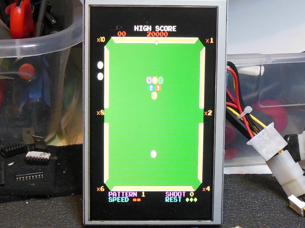
After a few more hours the screen became split into two identical halves. I suspected a vertical count issue and started inspecting the outputs of IC 7L/8L (LS161) that all looked to be running. IC 8K (LS86) outputs were running. IC 7K (LS86) pin 6 1V output was idle high, pin 4 input also idle high. IC 8N (LS74) pin 8 was low, pin 7 high and pin 11 clock input was running OK so I suspected IC 8N was bad. Replacing IC 8N (LS74) fixed the split screen.
|
During the last round of repairs to the video circuit the game stopped booting. Reconnecting the ICT, "ROM Test All" passed OK but the "RAM Test All" reported "E: 1J 8400 00 0F". Checking through all the other RAM's didn't find any more issues and IC 1J (2114) was socketed and thus quick to change. Replacing RAM IC 1J (2114) brought the game back to life but with no audio.
|
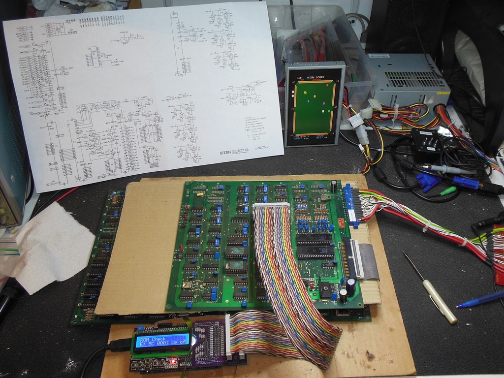
Starting with Arduino ICT, both the ROM check and RAM check failed. Setting
a repeated "ROM Read All" and poking around with a scope found the address bus
at EPROM IC 5E (2716) A0 - A10 looking clock-like as expected. The data bus
had poor low logic levels on pins 9,10,11,13 and pin 16 was all over the place
voltage-wise. Suspecting a data bus contention I checked the ROM OE & RAM CS signals
but both were as expected. "RAM Write-Read" read back "09 09 09 09" instead of
"01 02 04 08" on the lower nibble of the RAM and "00 00 40 40" instead of
"10 20 40 80" on the upper nibble of the RAM.
"ROM Check" on IC 5C reported "E: 0001 ce cf" and "ROM Read" reported "cf cf 0f cf".
"ROM Check" on IC 5D reported "E: 0801 3d 3f" and "ROM Read" reported "0f 3f 2f 0f".
In both cases the lower nibble was stuck and I suspected the IC 6C (2114) was bad.
Replacing IC 6C (2114) fixed the ROM check and the lower nibble RAM check but the upper
nibble RAM check still failed. Replacing IC 6D (2114) fixed the upper nibble RAM check.
Retesting with a Z80, the audio was working but the quality was very poor. I suspected a cap kit and cap polarity reversal was needed as learned from the other two Scramble boards repaired as part of the Scramble Restoration. After the cap work the audio quality issues were gone. However, whilst on the bench the board stopped booting again :(
This time the game got as far as clearing the screen, printing "1 UP" and then resetting. Retesting with the ICT discovered that ROM & RAM tested OK but the "Interrupt Check" failed with a timeout error. Inspecting IC 9M (LS74) found the inputs pin 3 CLK OK, pin 4 high and pin 5 high but the output Q high when it should have been low given the input pin state so I suspected it was bad. Replacing IC 9M (LS74) yielded a passing "Interrupt Check" and on retest the game was booting again but had lost audio again :(
With the ICT back in the audio board, ROM, RAM and AY-3-8910 checks all passed OK. Tracing from the AY forward with a scope confirmed audio output from the AY and audio output from the op-amp but only hiss from the TDA1010. The TDA1010 input was also sat at +12V versus the usual ~1.4V. Replacing the TDA1010 brought back the audio. The board set finally ran for a few more days without any further issues.
This board set was unusually tough going :|
|
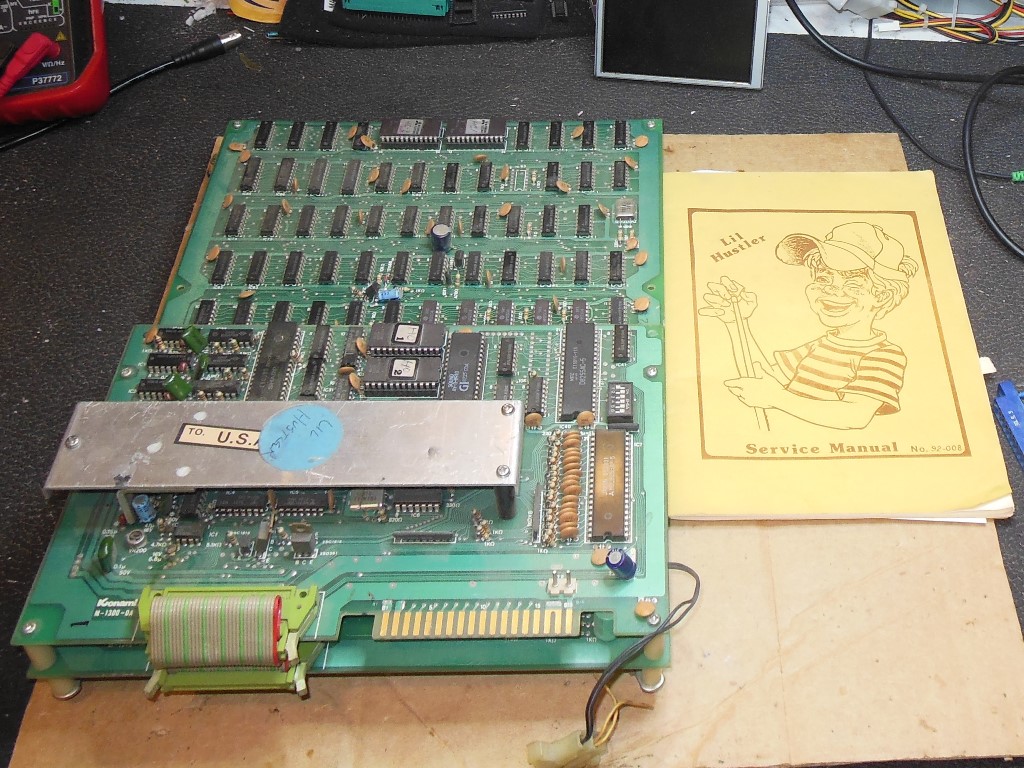
The spare PCB #003 that I'd previously struggled through repairing was a converted Scramble in poor condition with many faults. I'd placed a search on eBay for an original Hustler PCB to replace it consistent with the existing one in the cabinet. Though Hustler is not a popular game it does share the same base hardware as Frogger and thus often more valuable converted to Frogger than as Hustler. I got a hit on a listing for an original US release Dynamo Lil Hustler PCB & manual that first listed for $100 BIN and then relisted for $40 BIN that I then bought.

|
There was a mysterious fly lead with a plug on it that I removed & cleaned up. Visual inspection also spotted a blown -5V tantalum capacitor that I replaced.
The eBay listing mentioned that there was no sound but on the bench the sound seemed to be working except for a continuous background tone. Replacing the AY-3-8910 was all that was needed to eliminate the background tone and fix the sound such that the game appeared to be fully working.