

|
|
On show day 2 the sound stopped working, outputting only a high-pitched single tone. The spare game PCB was swapped in and the game ran for the remainder of the show with no further issues.

|
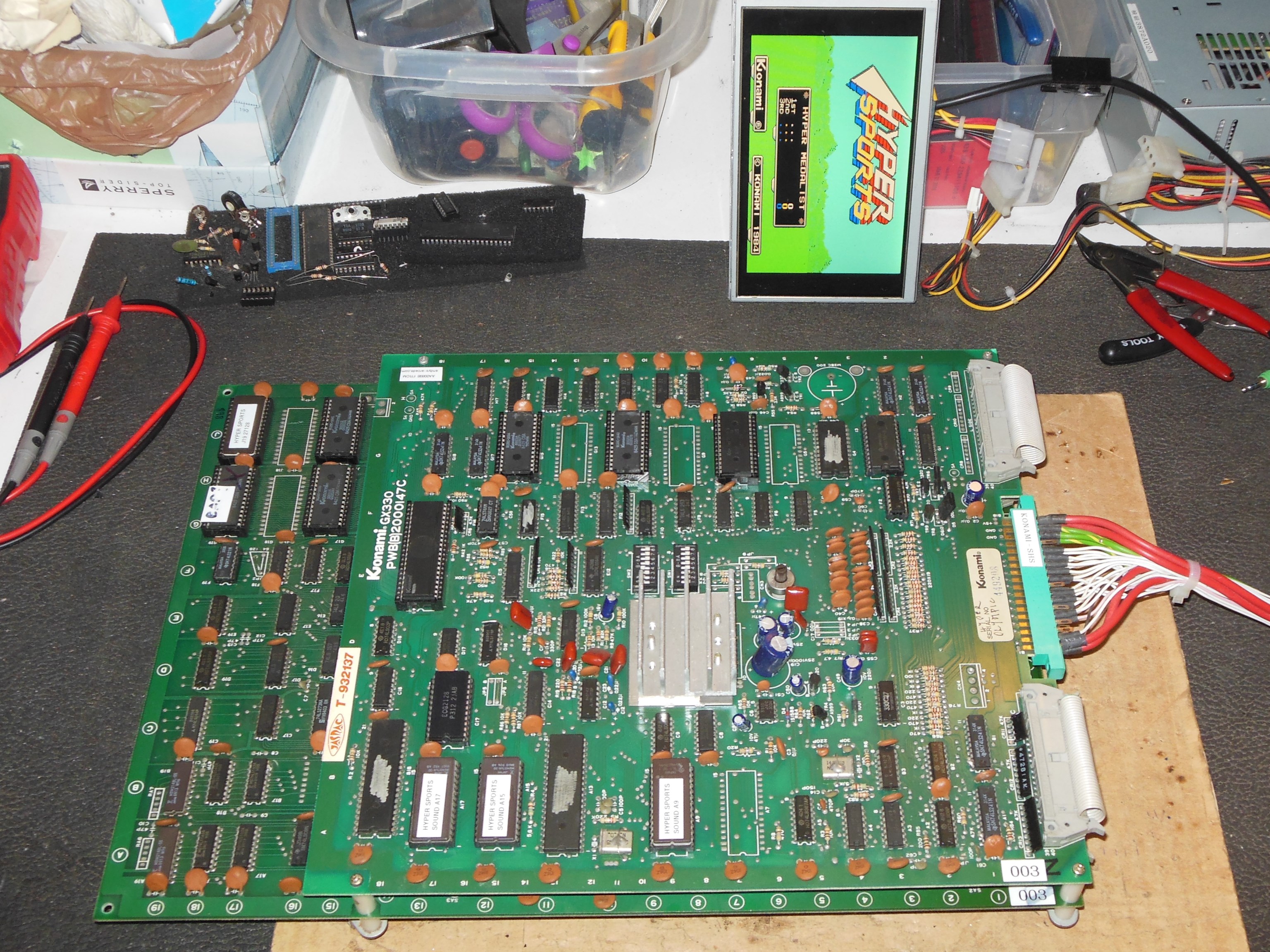
On the bench the game PCB output a single tone and no other sounds. The sound Z80 was
soldered so a cursory look around the Z80 with a scope didn't encounter anything
obvious. Pins 1,2,3 (A11, A12, A13) were idle low. IC C17 (6116) ~CE and ~WE were active
and ~OE idle low, enabled. Socketed RAM IC C17 (6116) was replaced but there were still no
game sounds however, during game play the speech was working. This was confirmed with
the original RAM also. No writes were seen at E15, the DAC latch, or on IC F13 (the
SN76489 latch). In game mode IC D17 (LS138) pins 13,14,15 were idle and pin 4 idle high.
Inspecting IC C18 (LS138) in coined up press start button mode found:
With no definative way to fault find with the game code running, the Z80 was removed and
a socket fitted with a replacement Z80, but still there were no game sounds other than speech.
Using the Arduino ICT with added support for Hyper Sports sound, ROM and
RAM tests passed OK. An input read of the timer found the lower 2 bits cycling OK. The
sound command read was 0x00 and then 0x3A on coin-up. Using a custom "Test DAC" function
on the ICT found no change in signal on IC D13 (uPC324) pin 10. Working back to IC
E15 (LS374) pin 11 chip select was idle high. Checking IC D17 (LS138) found:
|
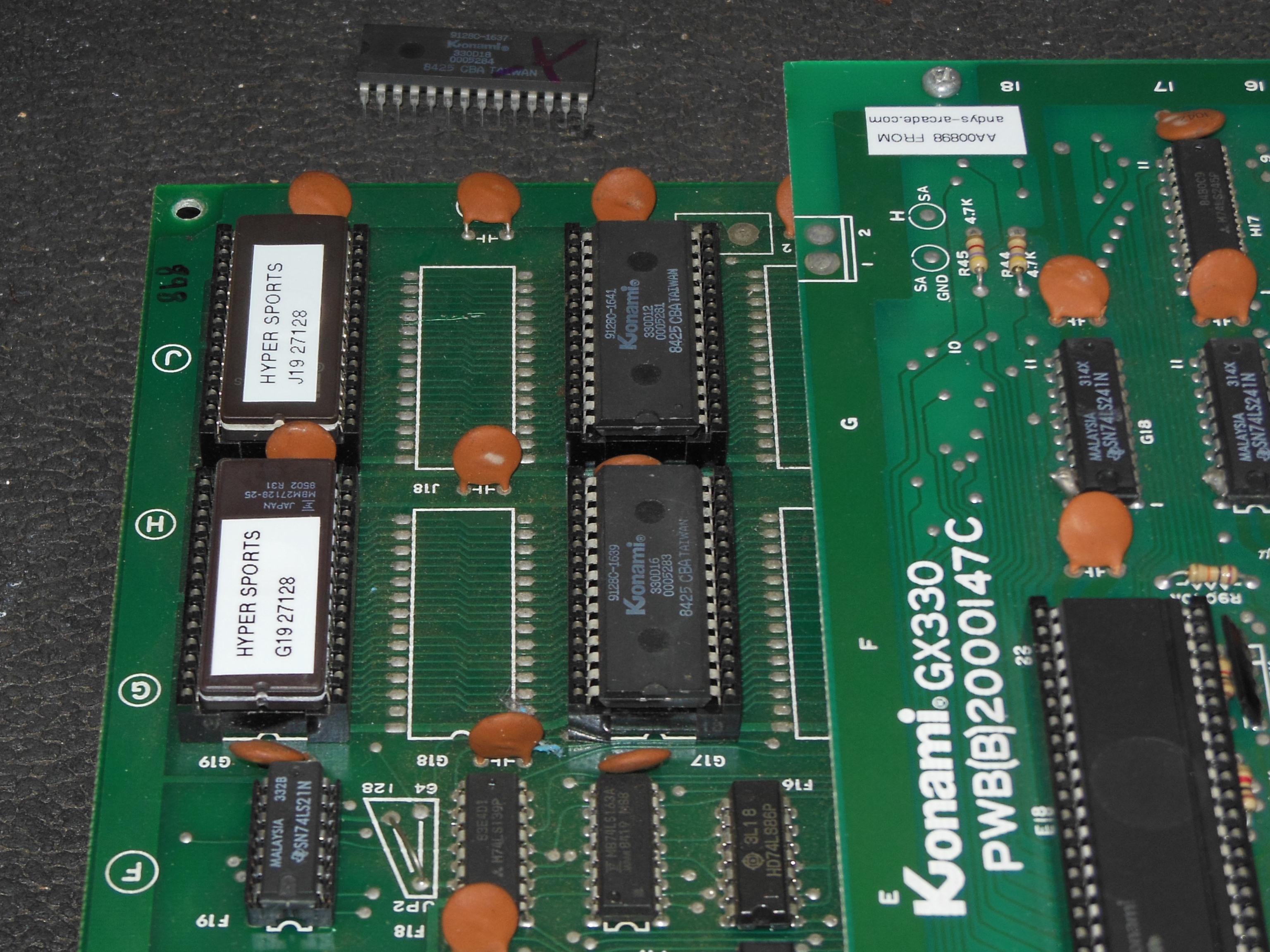
Pre-show testing had already identified IC G19 (masked ROM) as bad but there wasn't enough time left before the show to program a replacement. A blank 27128 EPROM was programmed that fixed the sprite graphics corruption.

|
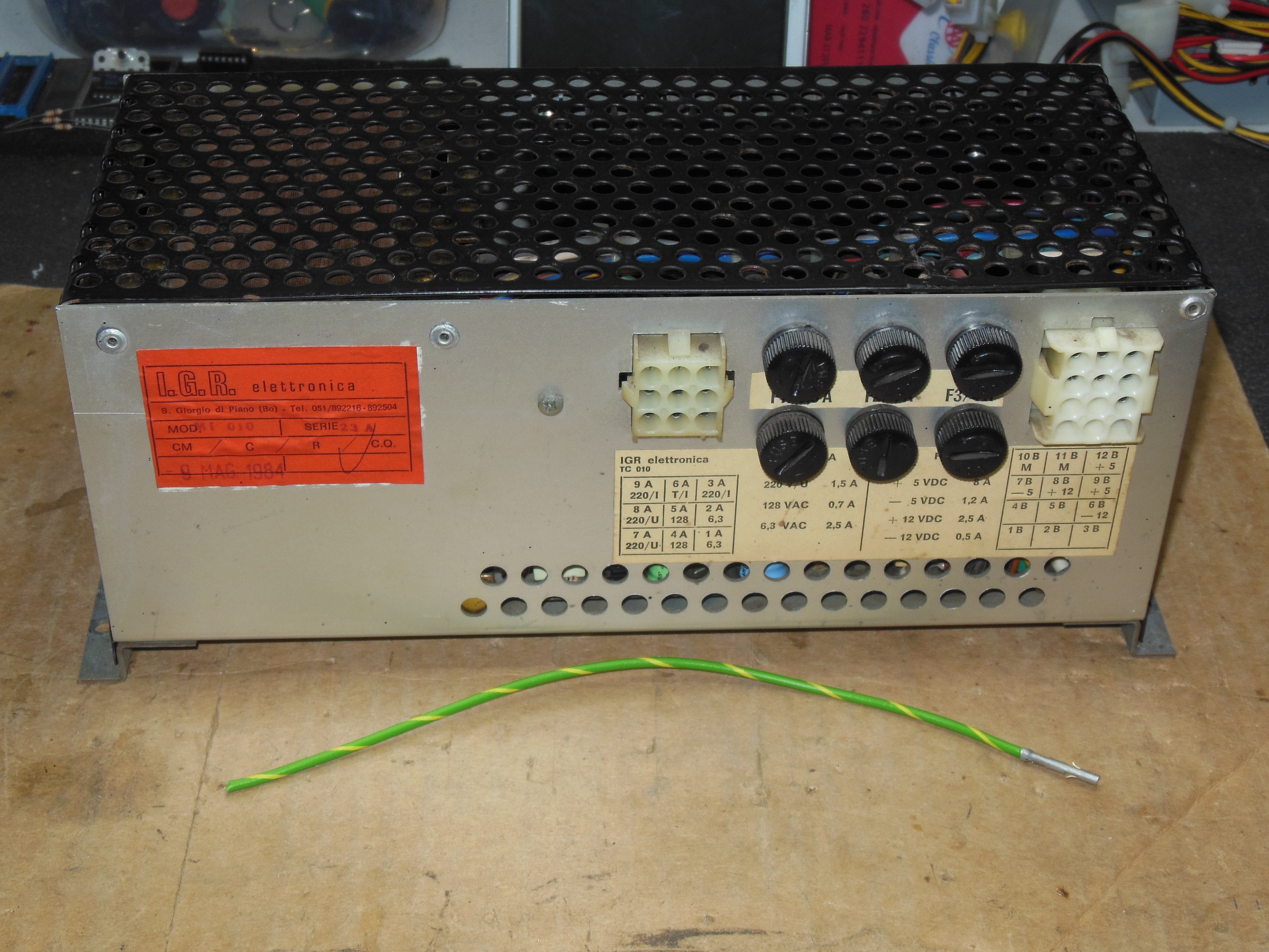
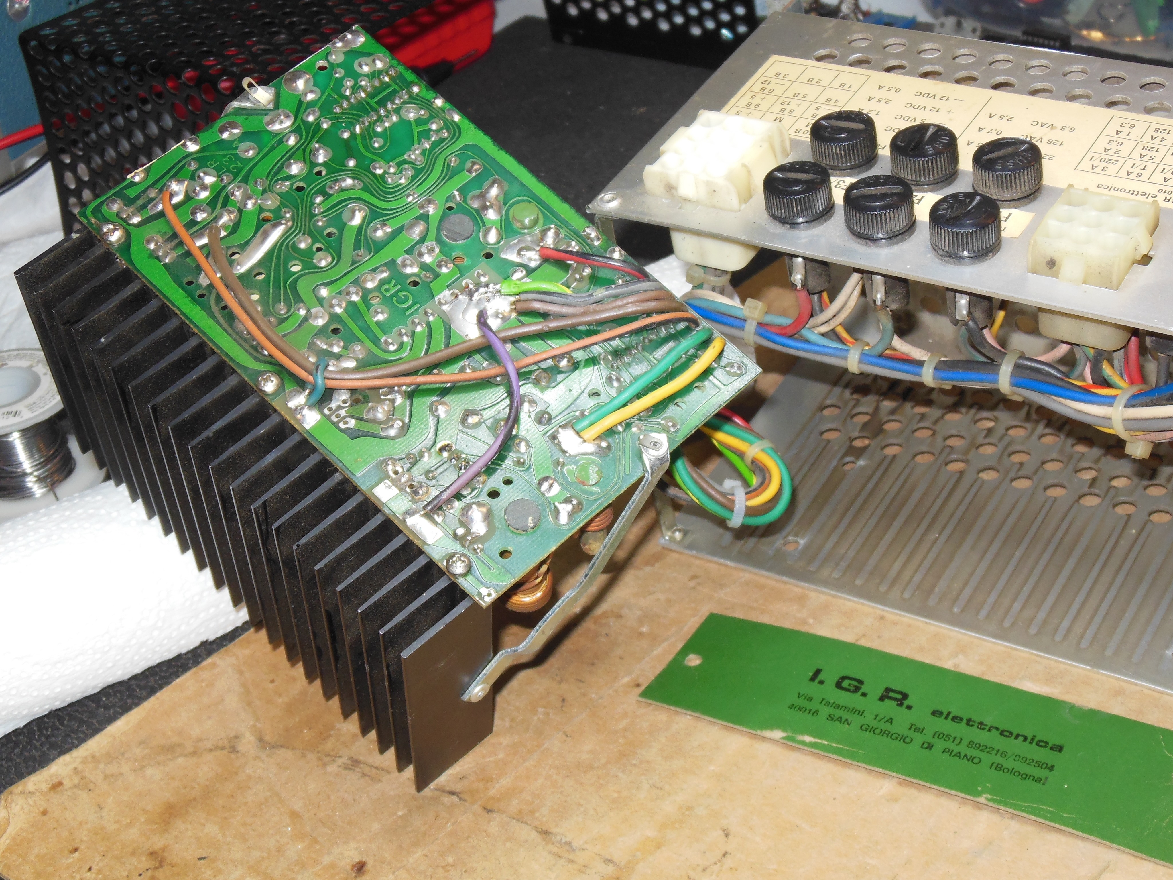
After the reliability improvement success of the cabinet fans fitted to Money Money and Jackrabbit, a fan kit was prepared for Hyper Sports (fan cabling and additional ground wire for the IGR power supply).
|
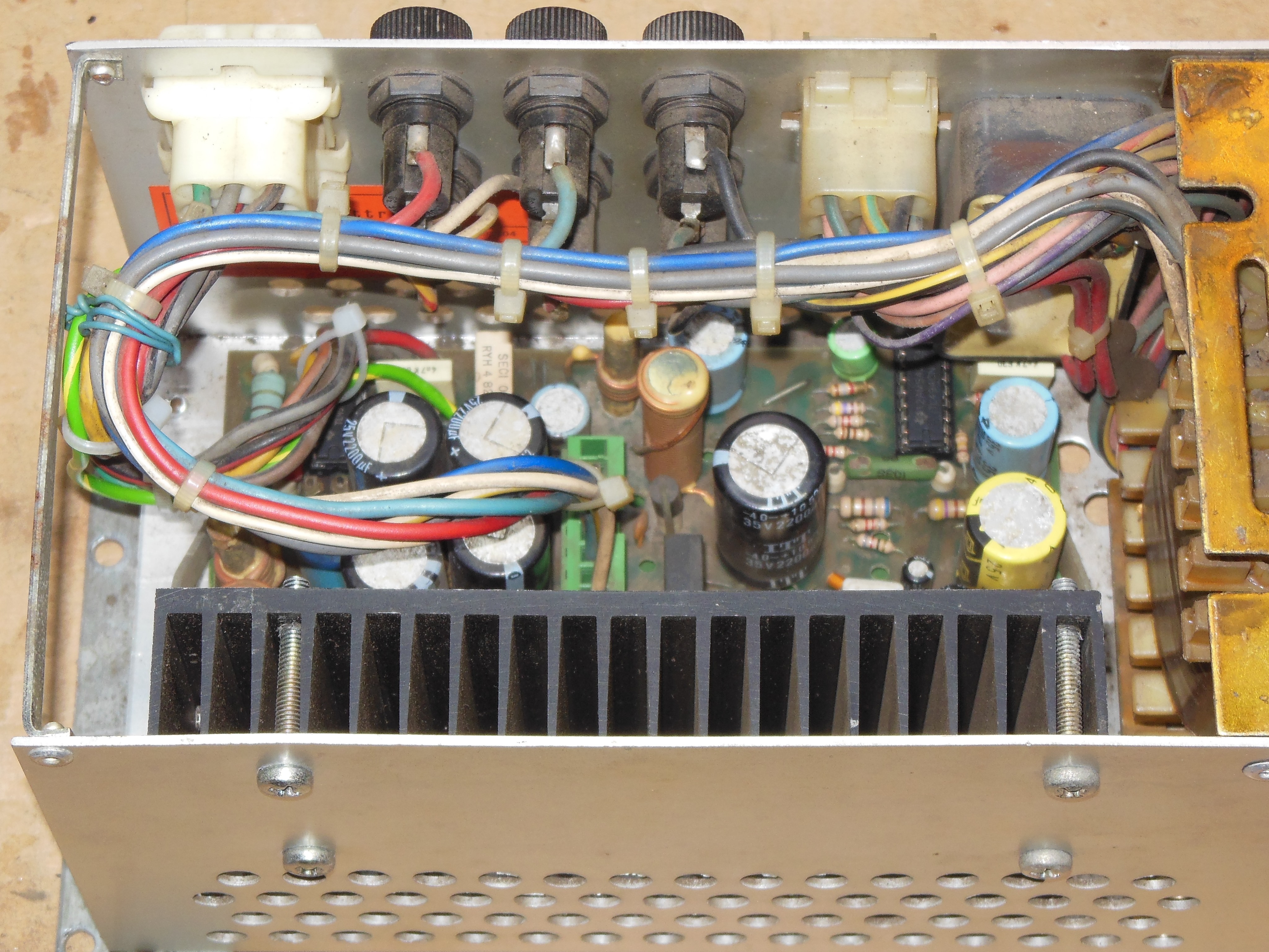
The additional ground pin was fitted to the the IGR power supply in an unused connector position.
|
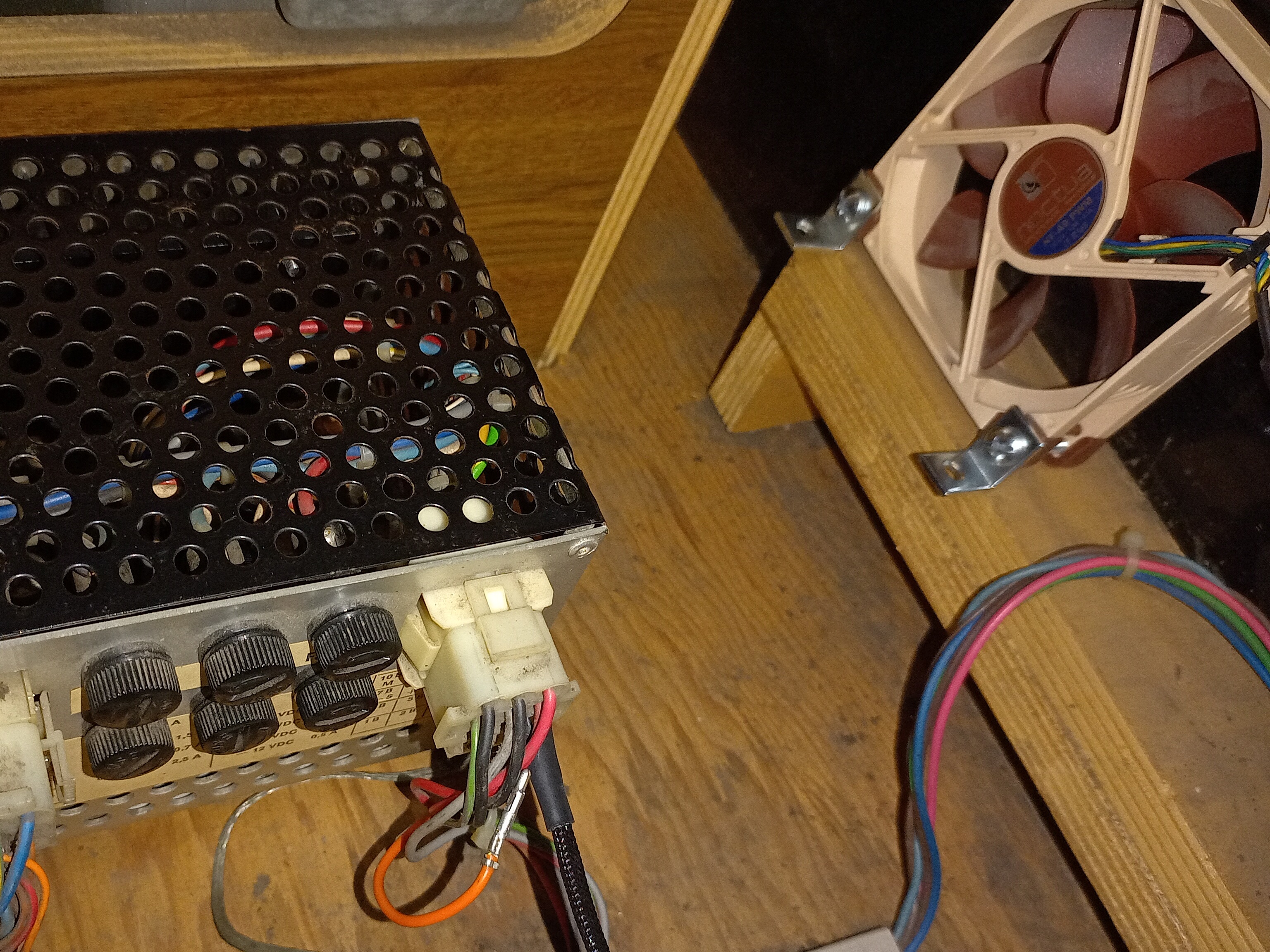
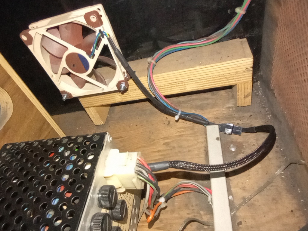
Unlike Money Money & Jackrabbit in the earlier cabinet, this wiring loom did connect to the -12V supply but the end point was tucked away unused. The pin was popped out of the connector, covered with shrink wrap and neatly zip tied to the harness (fully reversable). The fan was fitted to blow across the power supply towards the game PCB.
|
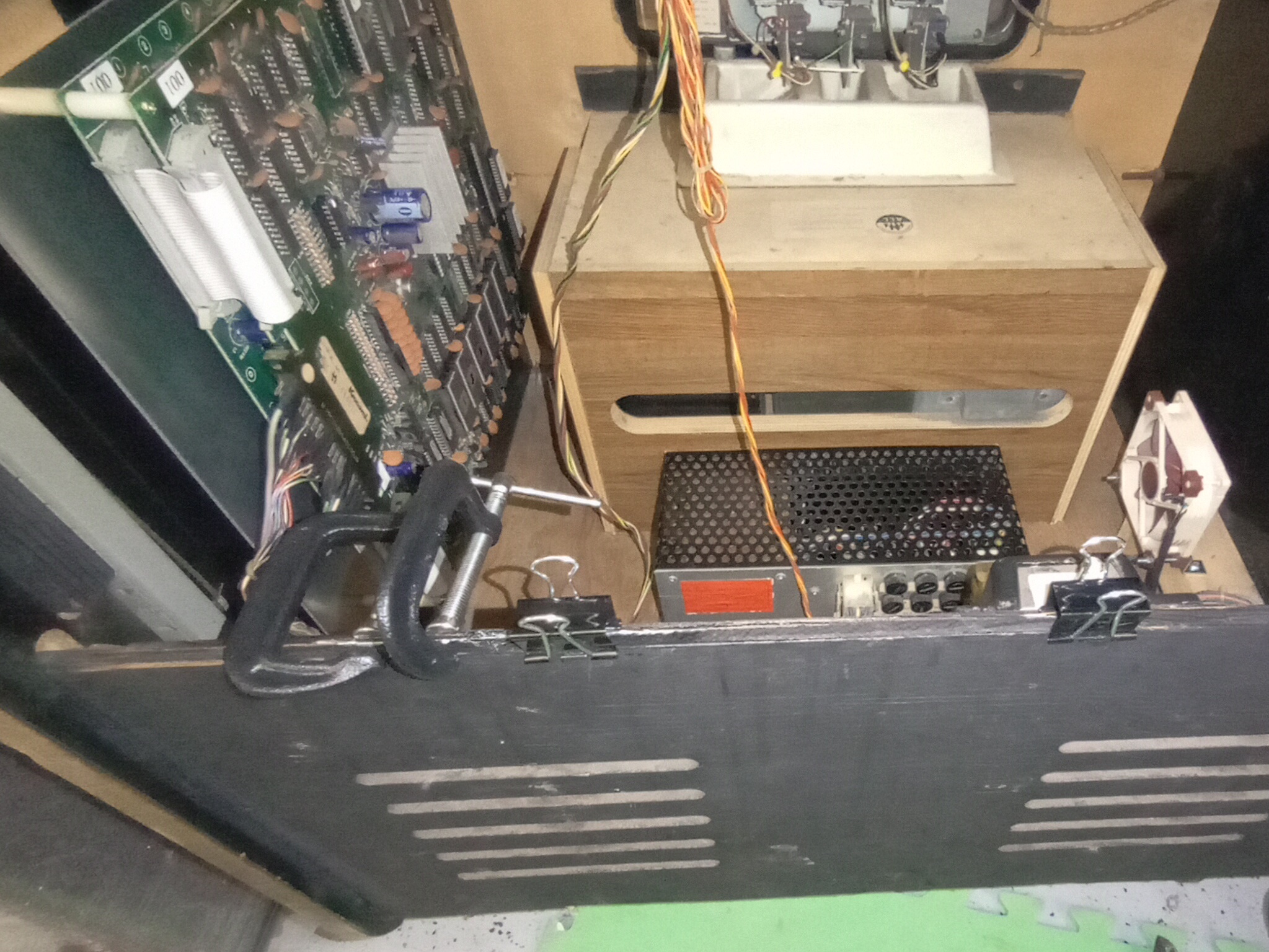
A wood split along the bottom of the door lip was repaired with wood glue and clamps.
|
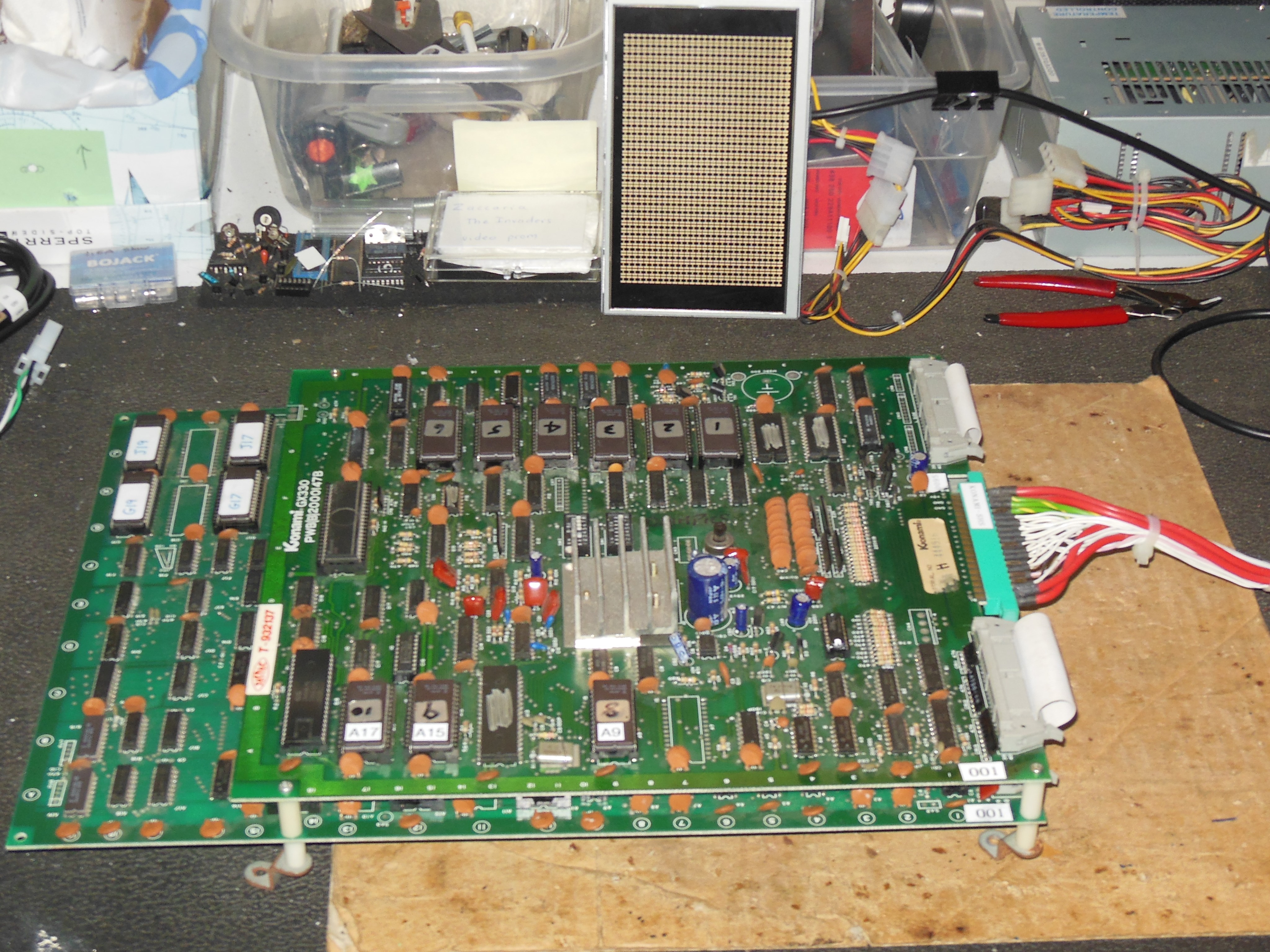
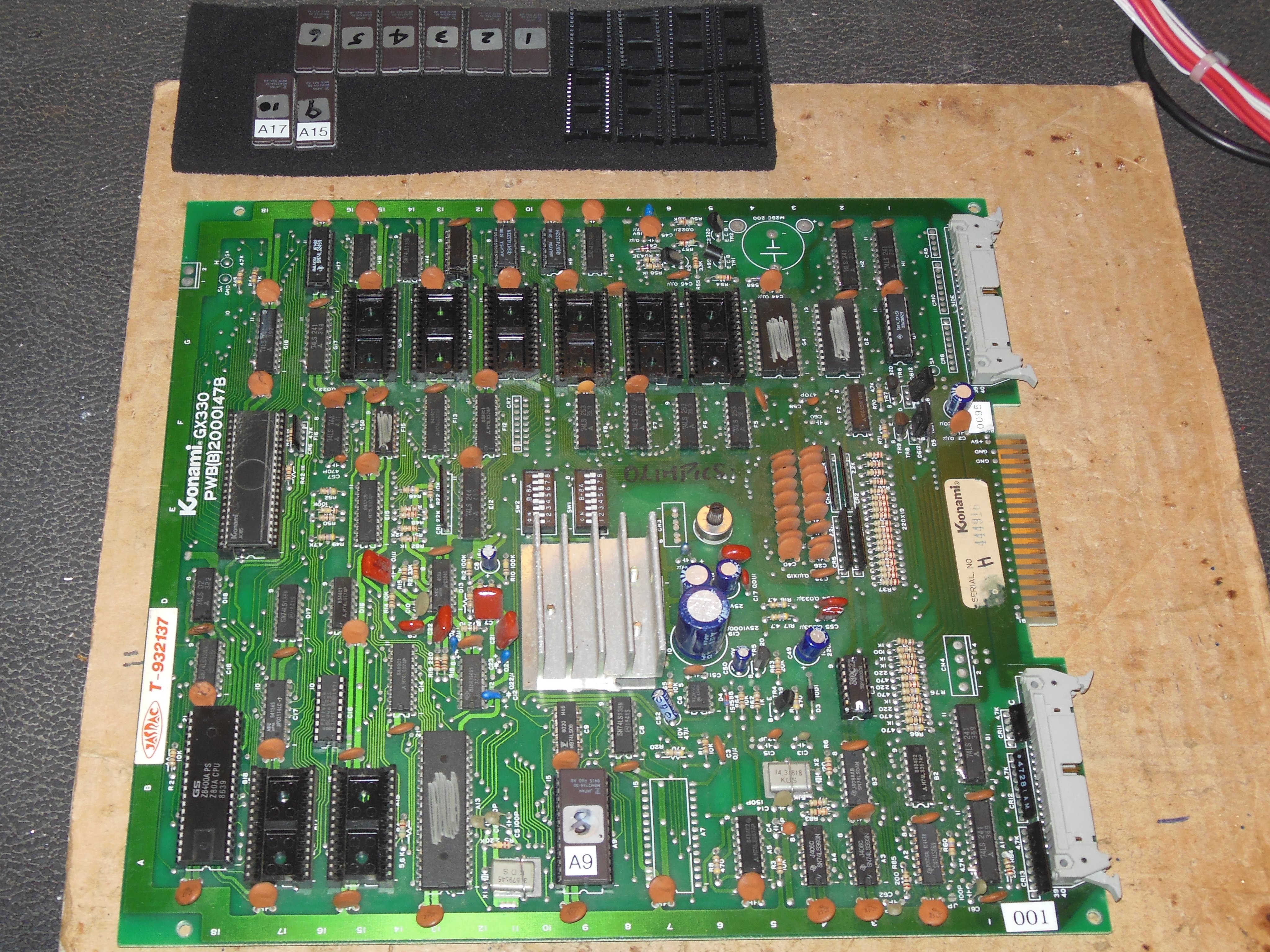
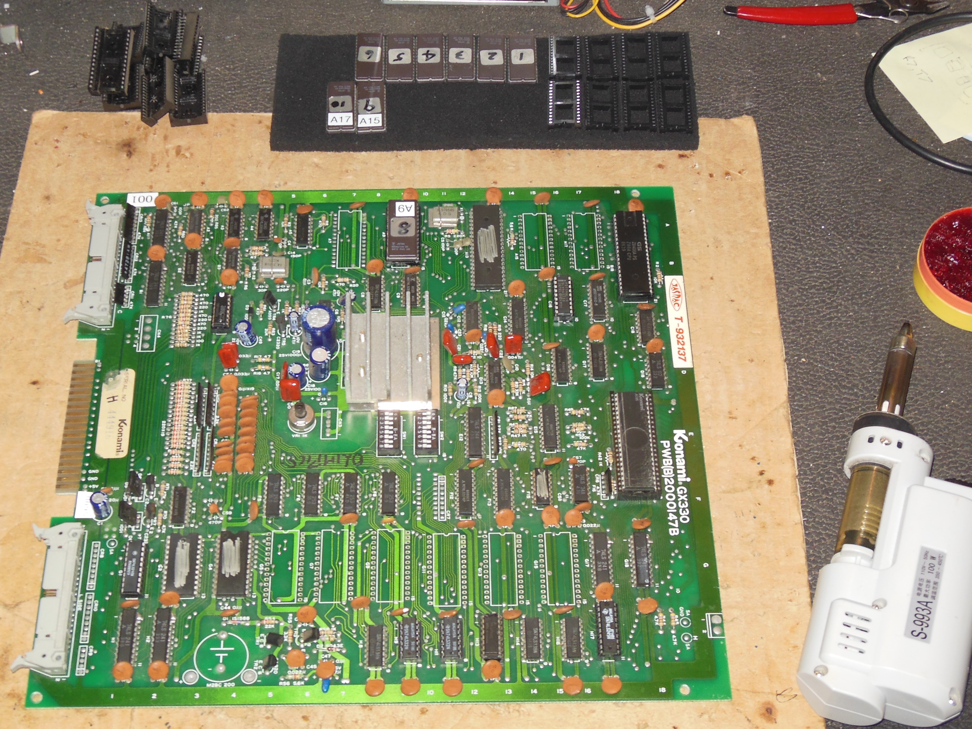
Pre-show testing found the game not booting reliably. Lifting ROM 6 (G17) slightly impacted the issue hinting at bad sockets or IC pins. This PCB had socket issues previously and the IC pins were already cleaned. Pressing on the sound ERPOM also caused sound glitches and I decided to replace all the sockets on the top PCB. After all the sockets were replaced the PCB passed the test ROM and the game ran OK.