

|
|
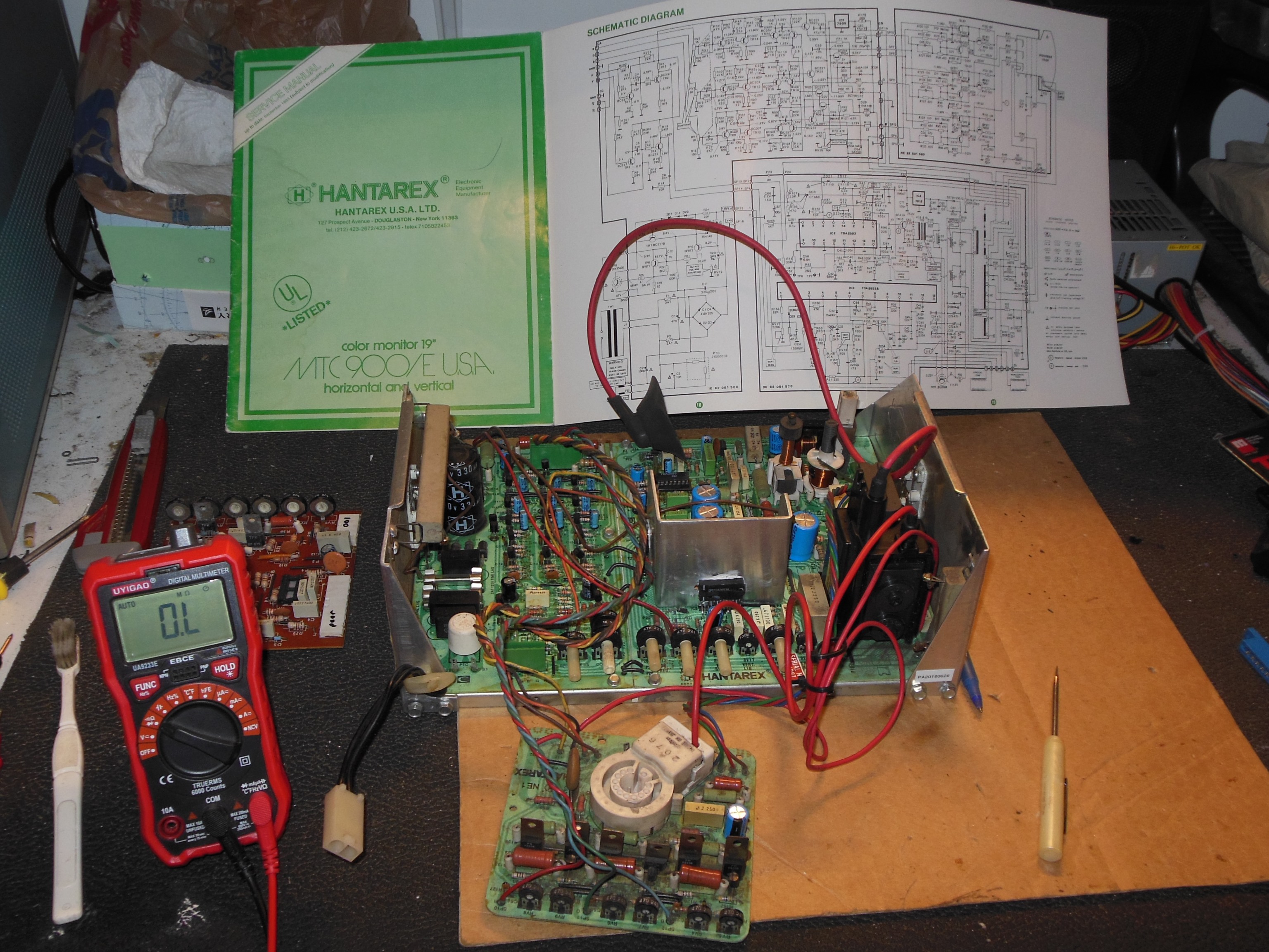
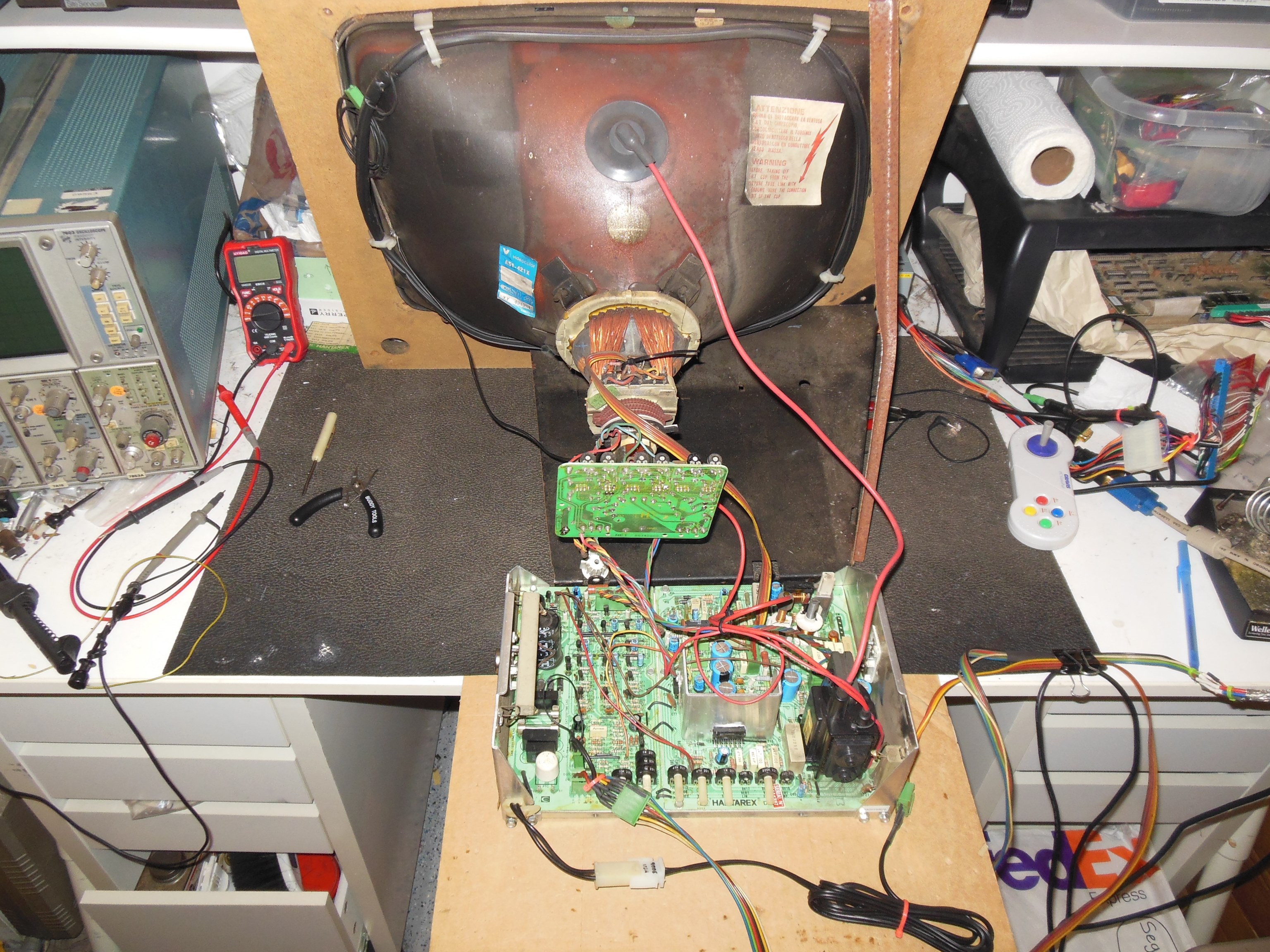
Pre-show testing encountered intermittent issues with blue that I suspected was a monitor problem. The monitor chassis was removed for repair.
|
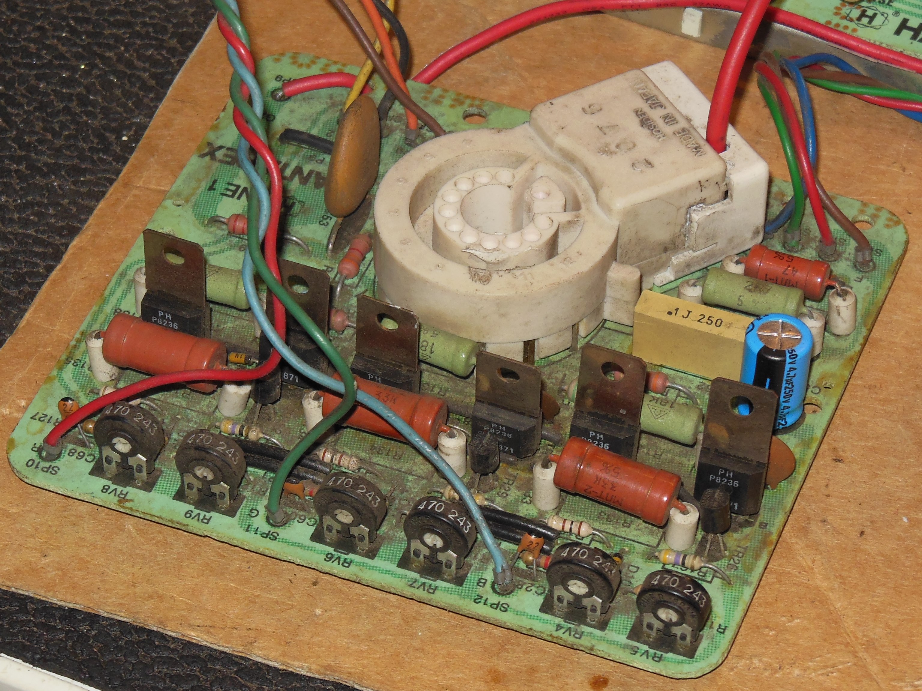
Starting with a static analysis of the neck board on the bench didn't find any anomalies
across R,G,B transistors using the back-to-back diode check. Similarly testing on the main
PCB colour drive circuits didn't find anything. Considering that possibly a neck pot was loose
I measured all of the pots:
|
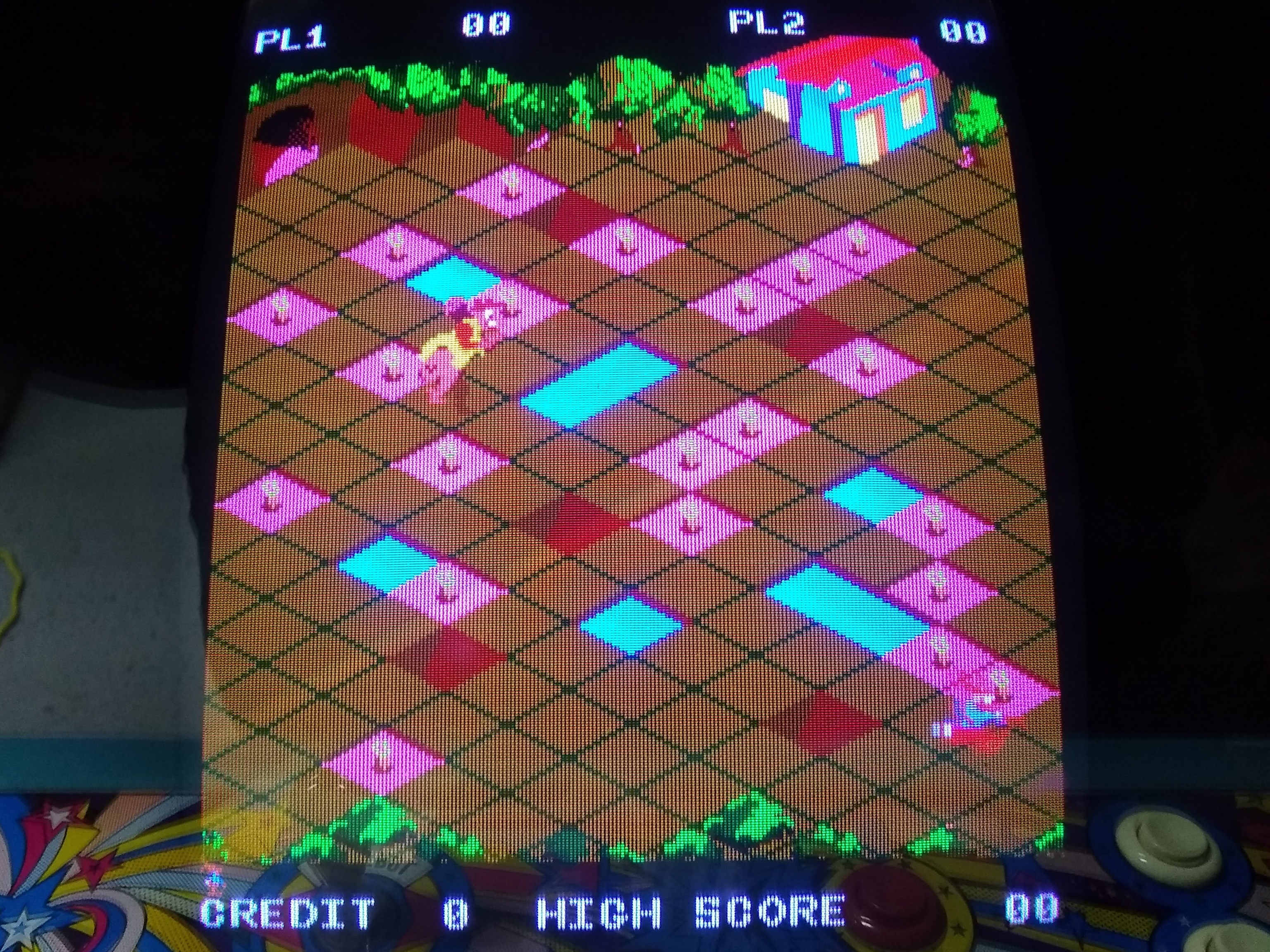
Back in the cabinet there were still intermittent blue issues and once again the chassis was removed for repair. Setting up on the bench and using a scope identified the blue instability as output from the main PCB. Using freezer spray confirmed the issue was in the blue pre-amp circuit. Targeting each transistor with a drop of freezer spray identified TR8 (BC547B) as susceptible. Switching a couple of times between freezer spray and heat from a soldering iron confirmed. Replacing TR8 (BC547B) fixed blue and eliminated any thermal response.
|
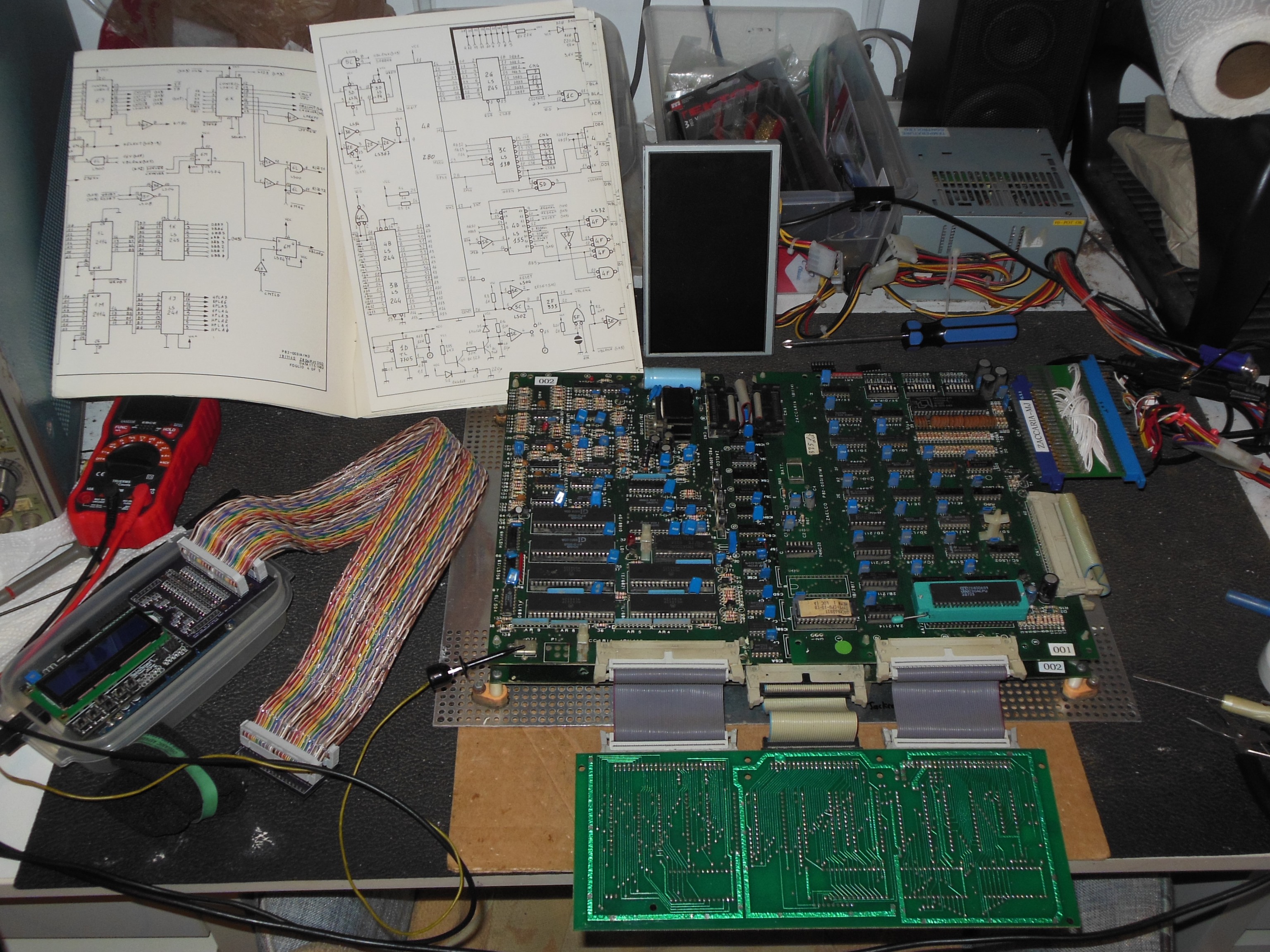
The spare game PCB was tested for a few hours on the bench and developed an intermnittant no boot & resetting issue. Checking the Z80 pin 26 RESET found it unstable & noisy. Checking IC 5C (LS02) pin 1 output was high with a lot of low noise. IC 5C pin 2 input watchdog was firing cleanly but IC 5C pin 3 input was low with high noise and borderline logic high. Working back to IC 5E (LS04), pin 3 input was idle at ~1.1V, borderline, and appeared to picking up pin 5, a clock. The output was also not inverted, and I suspected IC 5E was bad. Replacing IC 5E (LS04) fixed the noisy signal but now reset was stuck active. After a few minutes, the noisy signal returned. I suspected the reset circuit transistors Q1 or Q2 were bad. Q2/T2 (BC327) was removed and tested bad out of circuit. Both Q1/T1 and Q2/T2 were replaced with equivalents (BC327 === BC557 and BC548 === BC237). IC 5E inputs looked OK and the game ran without issue.


|
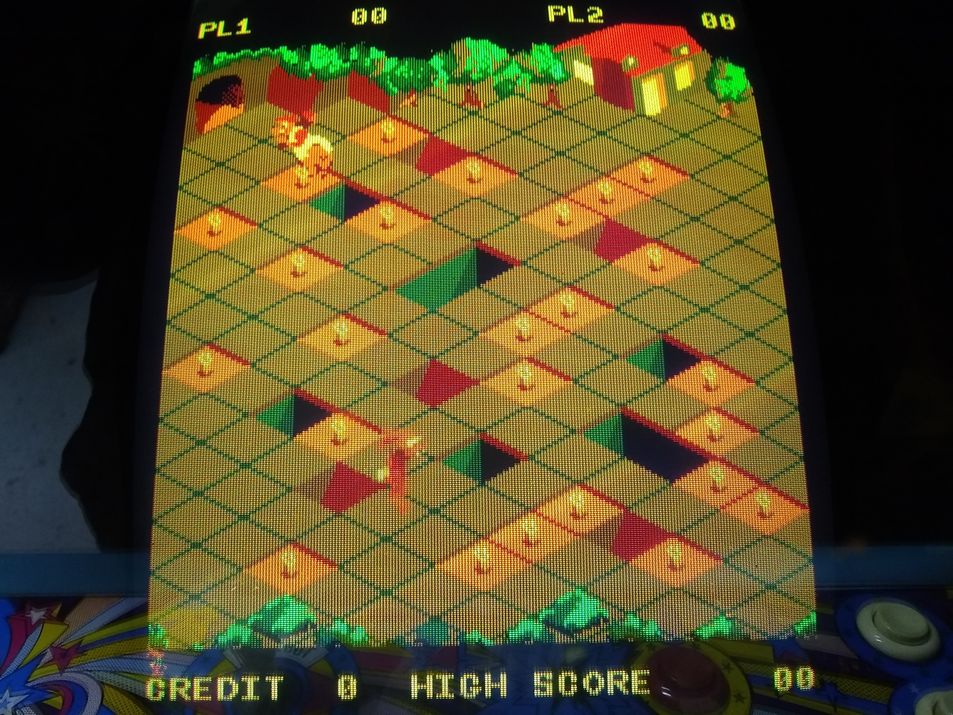
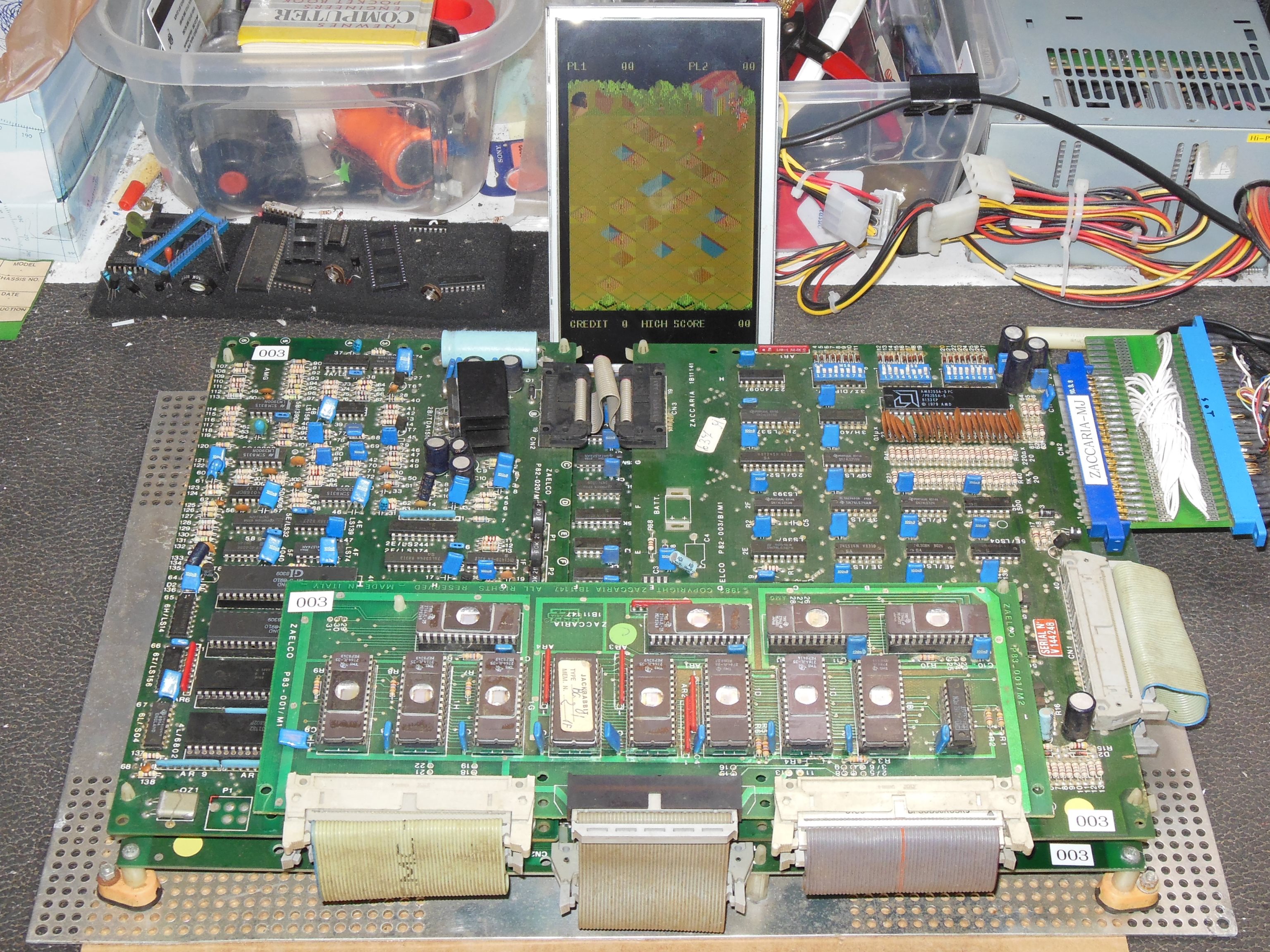
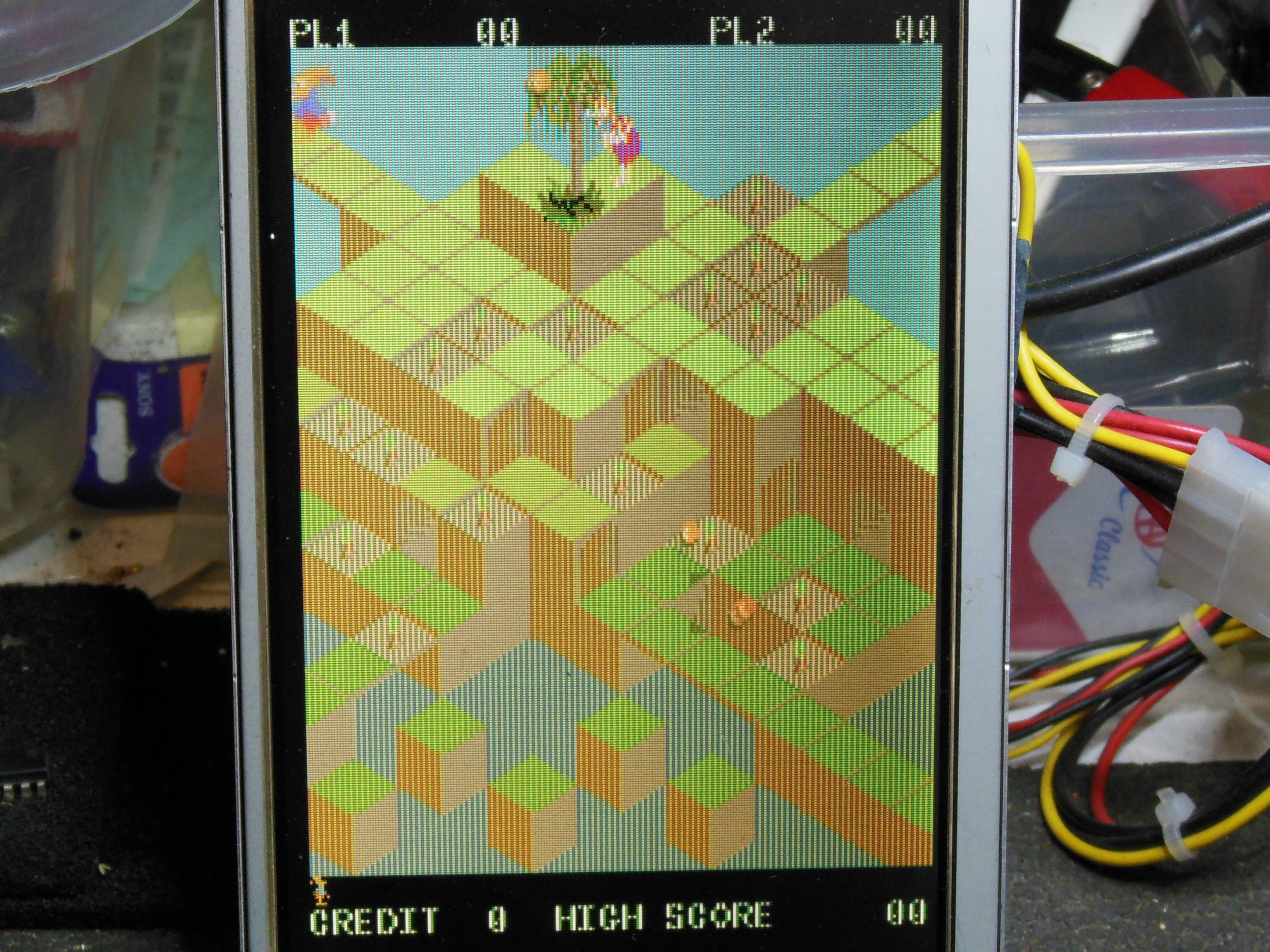
During cabinet testing for the monitor fix, the game PCB developed lines in the picture and was removed for repair.
|
According to the schematic the final line mixing between the two alternating line circuits
was done at IC 9E,9D (LS157). Checking the mixer outputs with a video probe found: