
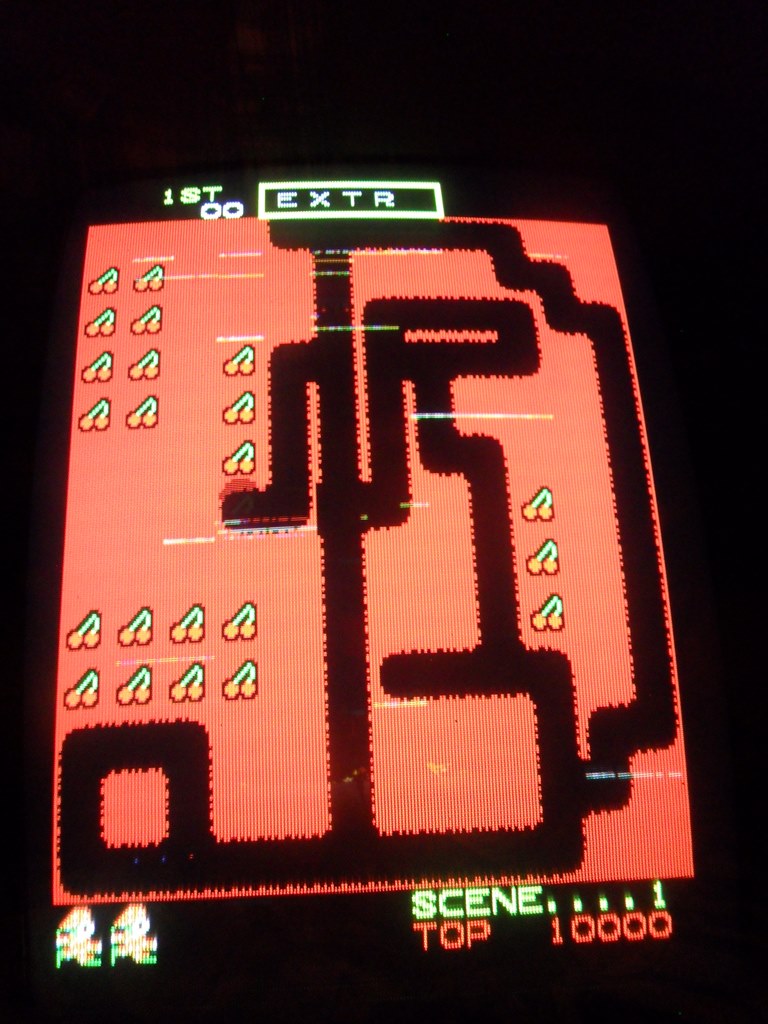
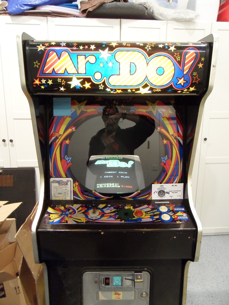
Submitted for the first time into the show as one of ten machines. The game ran for less than a day with intermittant focus issues and then the monitor died completely :(
|
|
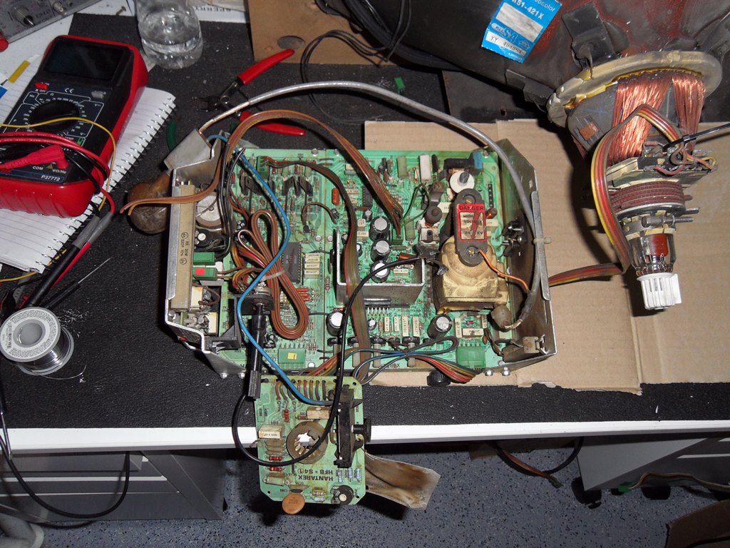
Whilst swapping out the TDA 2593 it became clear that the socket it was in was shot. Changing out the socket brought back HV but a blank screen still. Poking around with the scope there were signals going into the RGB preamplifier IC but no RGB drive coming out. Brightness and contrast didn't bring up scan lines either. The RGB pre-amp is in a socket (that I'd already changed out previously) and a replacement didn't change anything. Back poking around with the scope and comparing the blanking signal shown in the manual hinted that something was up with it on the chassis - diagram 7 looked very poor on the chassis by comparison. The BC237 at TR8 driving it was bad.
|
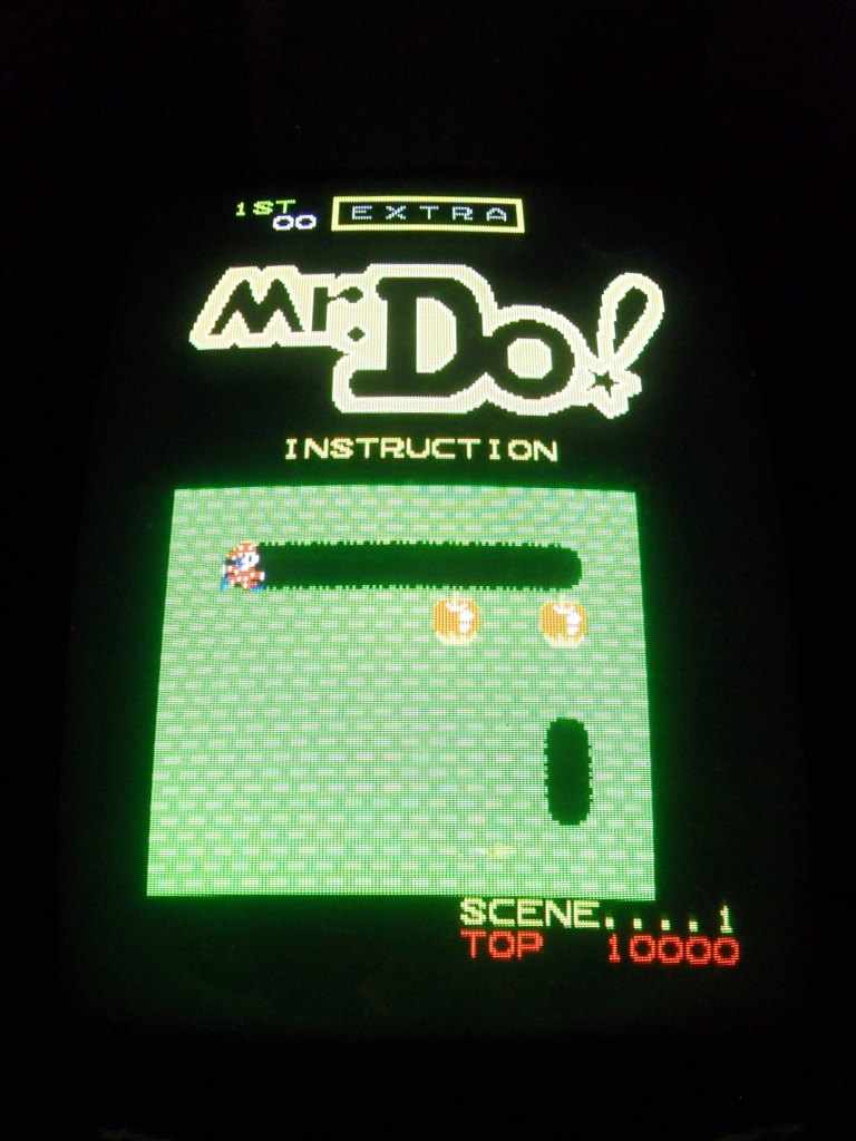
The picture looked pretty good on the bench and ran fine for a few hours with no further issues.
|
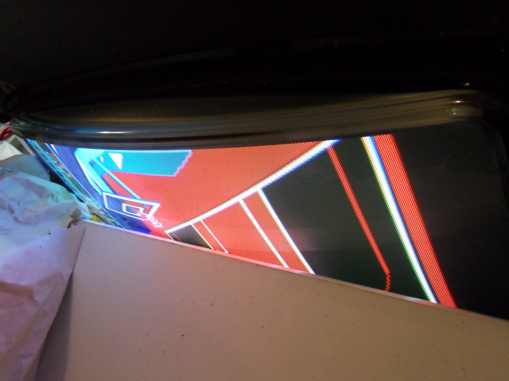
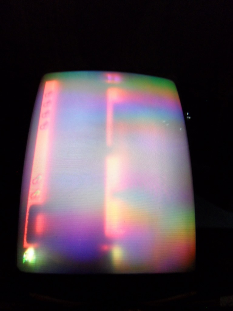
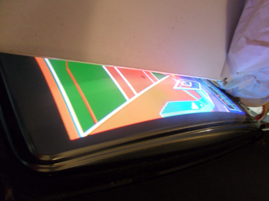
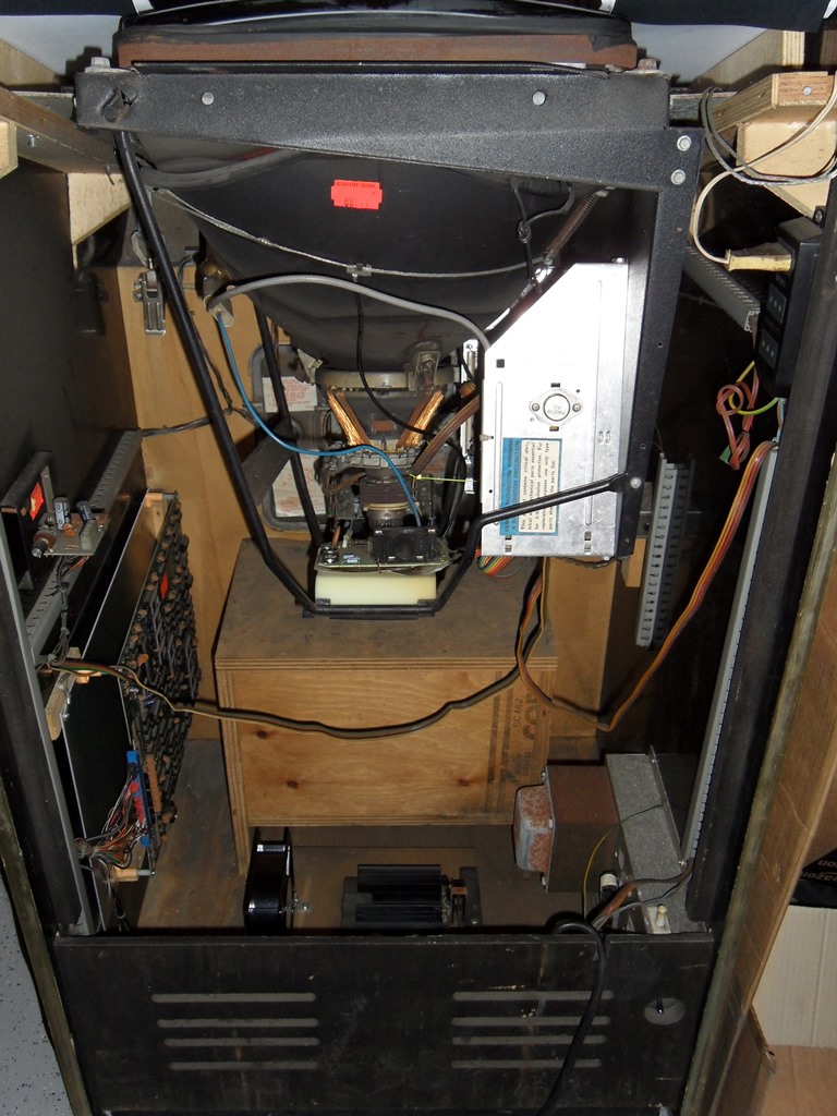
Alas, even though the chassis was working perfectly on the bench back in the cabinet it was a mess and still had the original issue it had before :( On a near all green screen the focus is super sharp but the brightness uneven. On a near all read screen the focus is completely lost sometimes accross all the screen and sometimes accross only half the screen. I checked the supply rails, 128Vac was 127Vac and the 220Vac was 237Vac, both OK.
|
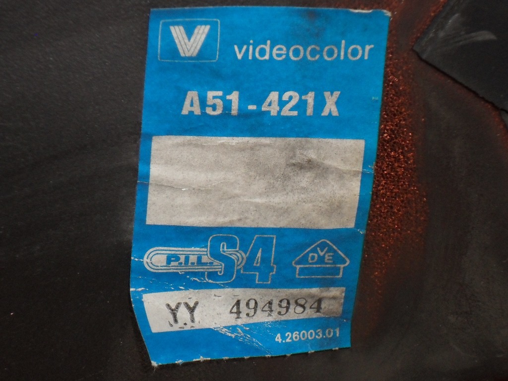
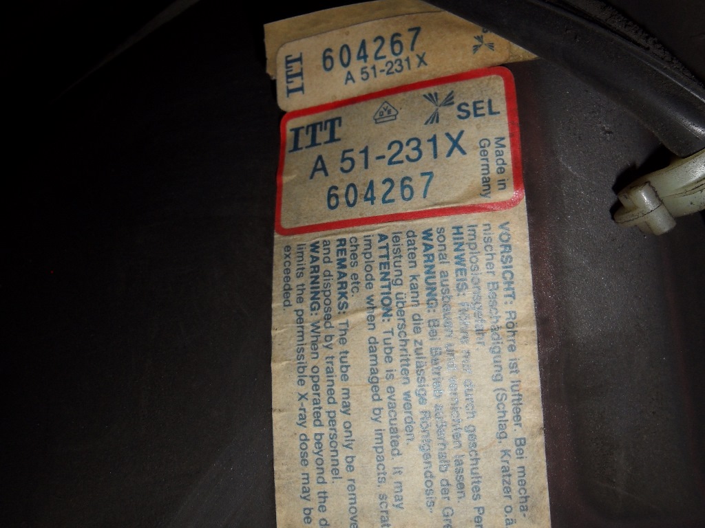
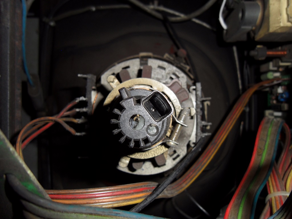
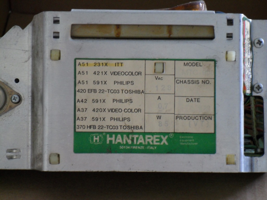
I noticed that the CRT in the cab was an ITT whereas my test tube was Videocolor.
I also noticed that the chassis itself had a Videocolor label and further examination
of a number of chassis showed they appeared to be often labelled with the CRT used. I wondered
if there was a possible chassis incompatibility between chassis & CRT types. The manual
showed three neck boards, a different one for a different ITT CRT but no reference to
this particular ITT CRT that appears pinned the same as the Videocolor neck PCB. After
consulting with a monitor guru in the UK, the opinion was that there is no known difference
between these tubes and chassis, and what I have is a bad CRT :(
The next step is to analyze it with a B&K 467 once I have a CRT adaptor sourced for it.
Fingers crossed.
|
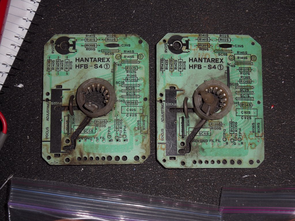
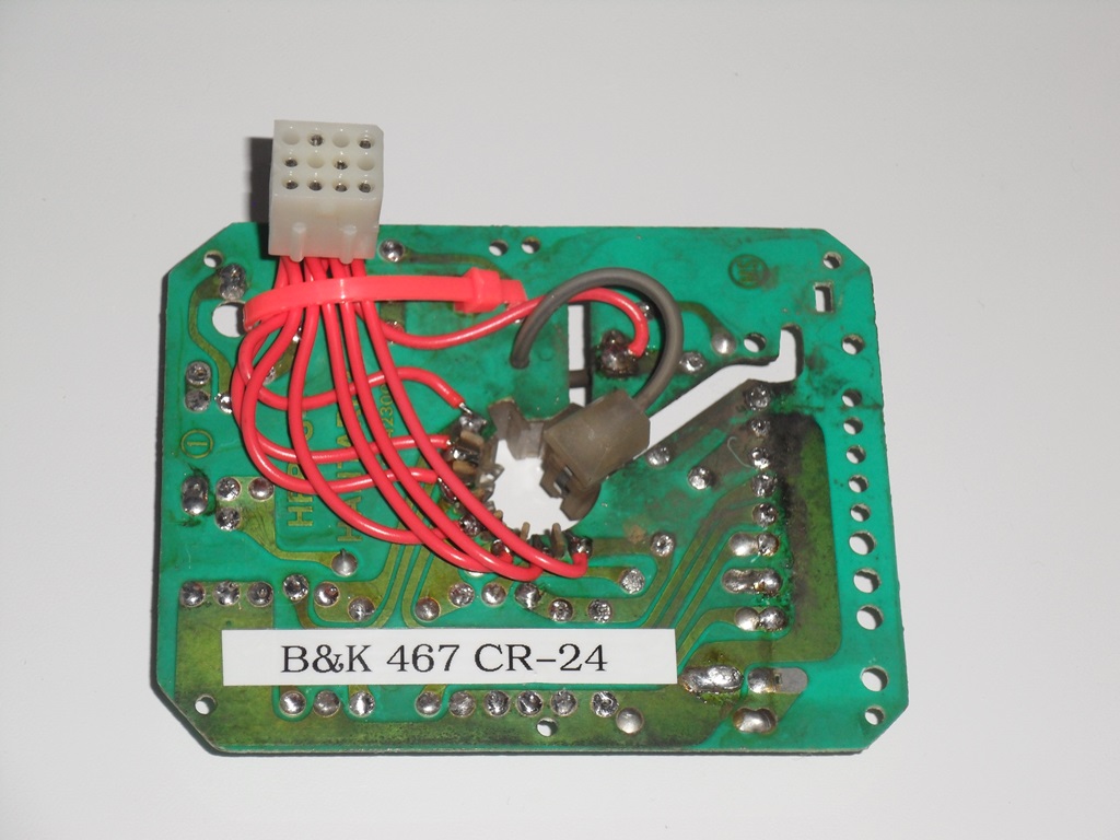
So it turns out that the CR-24 adaptor is hard to find or build because the neck sockets are long obsolete. Stripping a couple of neck boards from scrap chassis provided a couple of donors that could be used to make up a couple of CR-24 adaptors (a fellow collector made one up for me).
|
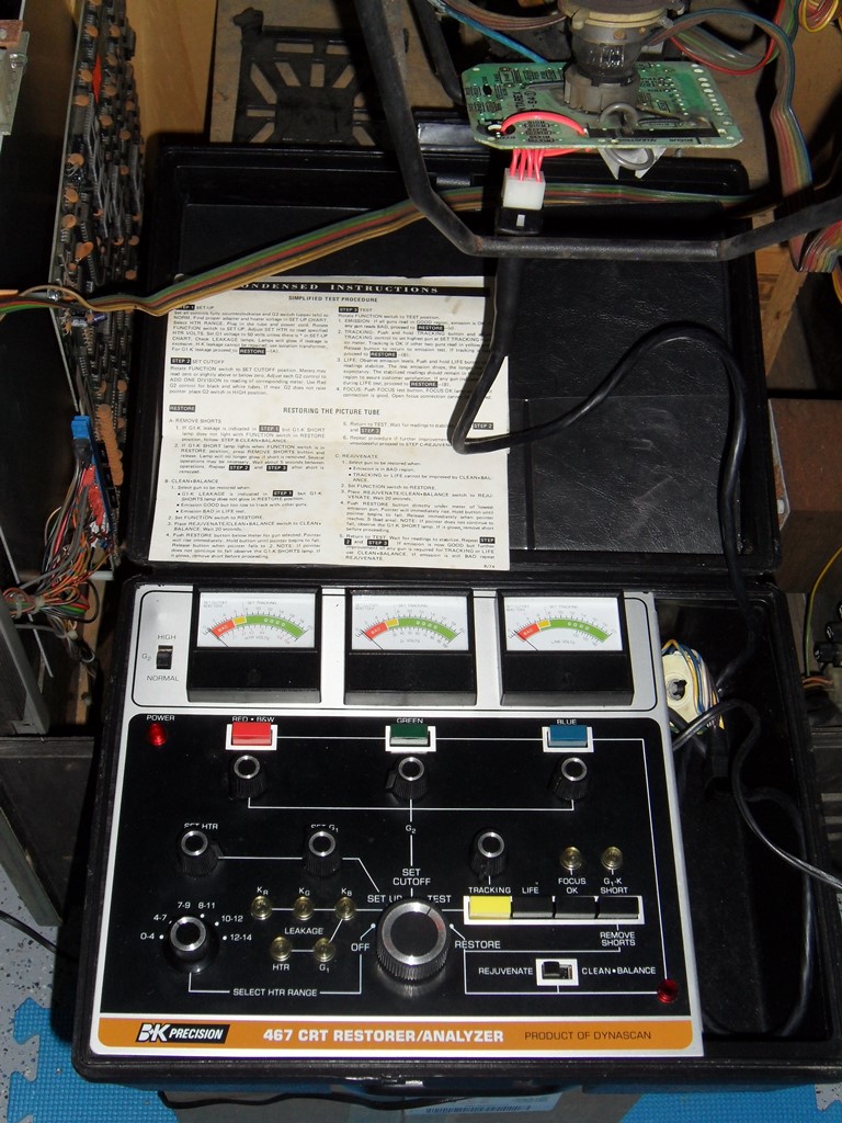
I wasn't able to get any sensible readings from the BK 467 on either the suspect ITT CRT or the Videocolor CRT. In setup the meters were either 0 or off scale. This tester was bought untested off eBay so I've no idea if it works or not - I will have to cross check the tester at a repair party some time and repair it if needed.
|
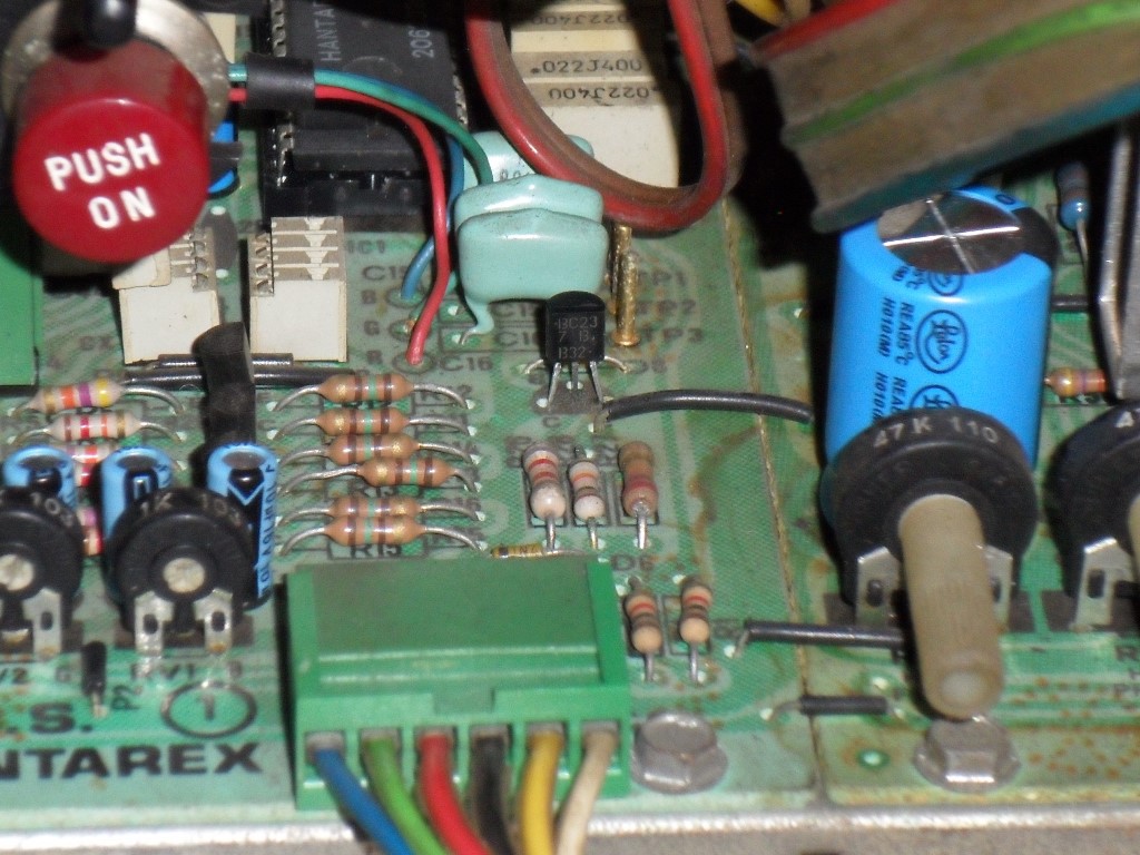
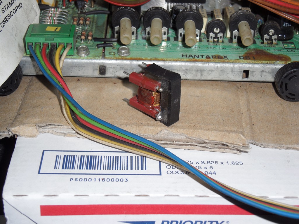
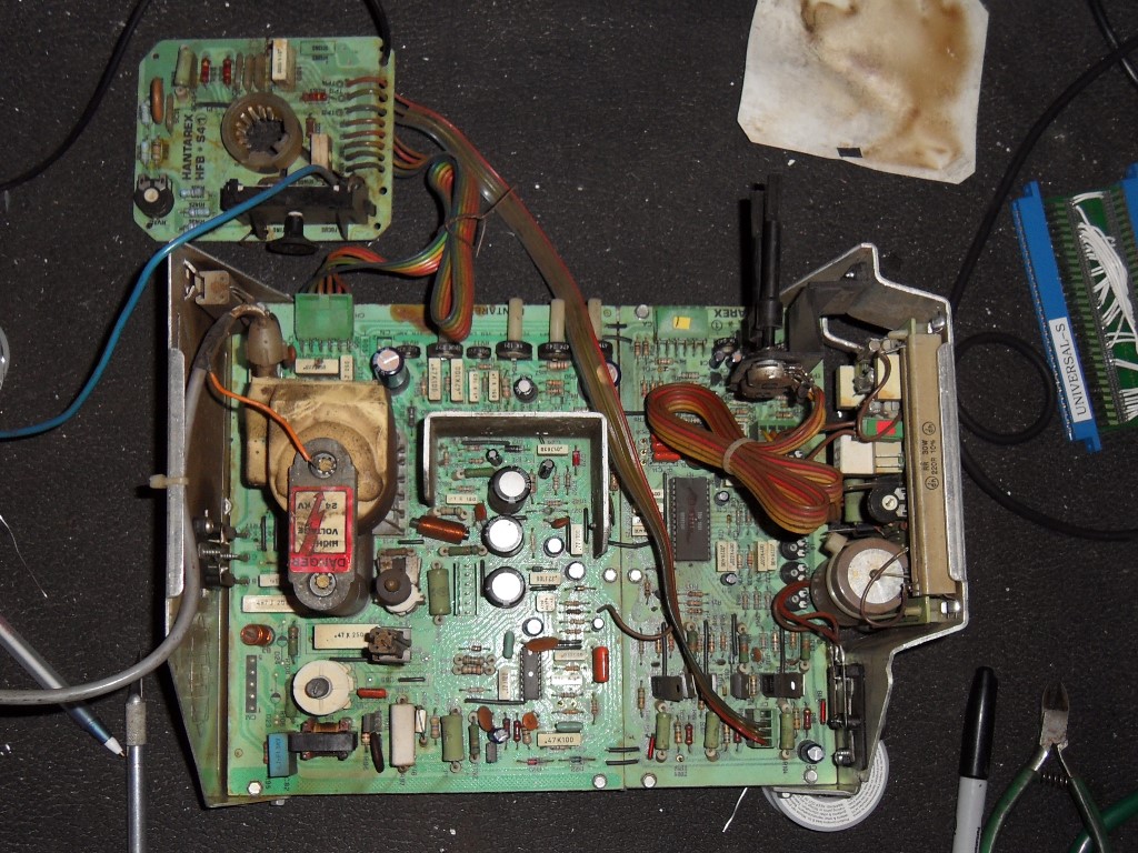
Digging through some boxes of salvaged chassis turned up an MTC-900 configured for an ITT CRT. The idea was that maybe the Videocolor configured chassis might not be a perfect fit for the ITT CRT in the cabinet (must have been swapped out some time in the past). One difference is that the ITT chassis has no East-West PCB and no connector or associated components for it on the main PCB. This ITT labeled chassis looked clean but was dead. Poking around with a meter showed the TDA 2593 had boot strap power and the scope showed oscillator output from it (changing it anyway made no difference). A monitor guru in the UK pointed me at a common problem of the transformer TH2 wires breaking off the posts and he was exactly right :) I popped it out, scraped off the wire and reattached it.
|
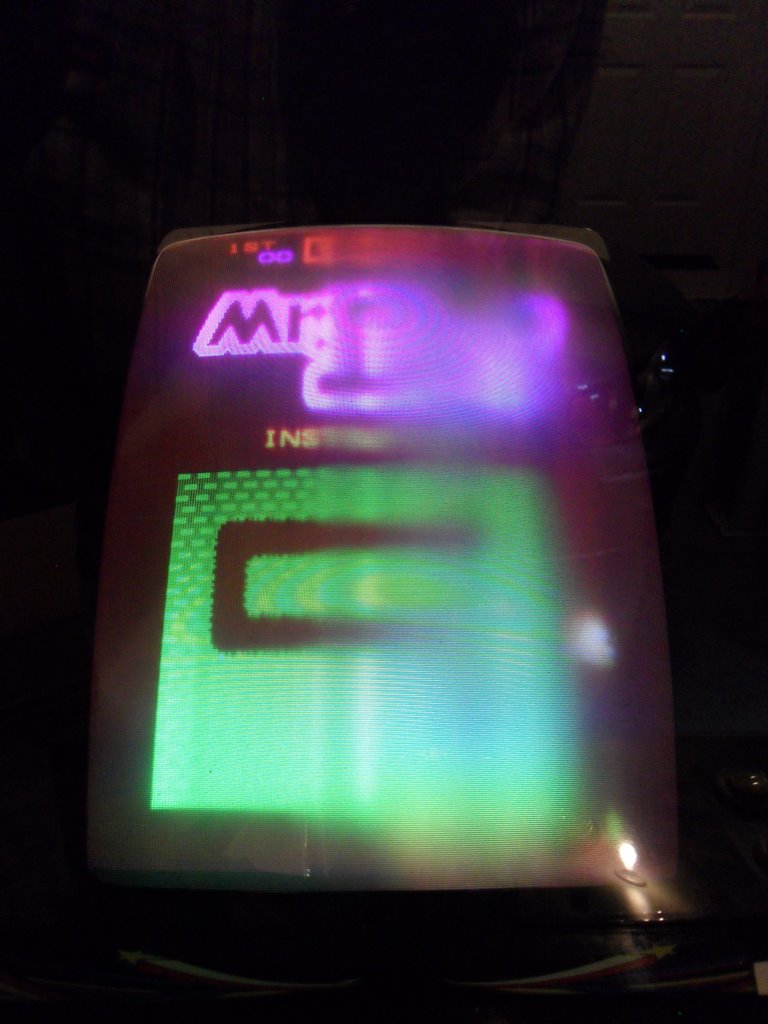
The broken wire seemed to be all that was wrong with it and the picture looked complete and good on the bench on the Videocolor.
|
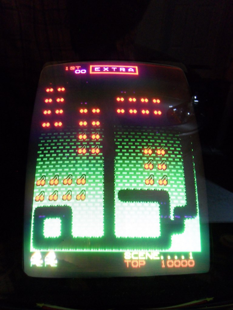
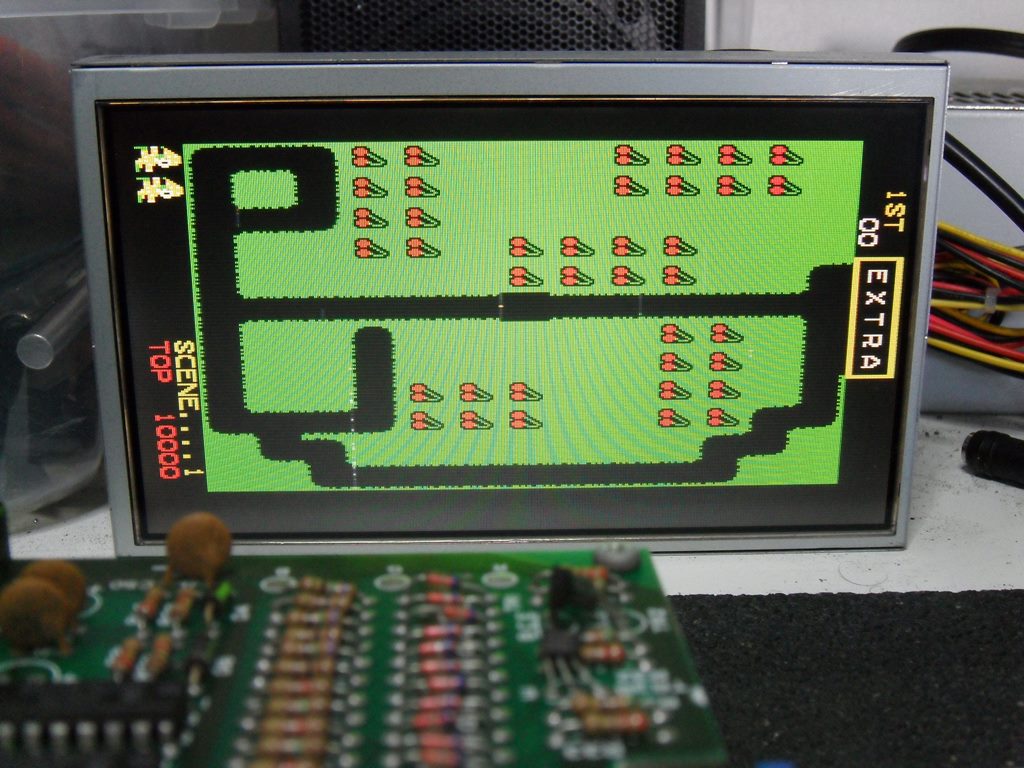
With the ITT configured chassis installed in the cabinet the picture looks good. The focus failure that occured with the Videocolor chassis was reproducible if the brightness and contrast are both maxed out, so likely the CRT does have an issue, but so far it's working fine with normal settings (ran for a few hours). The game board has a sprite fault that needs to be fixed.
|
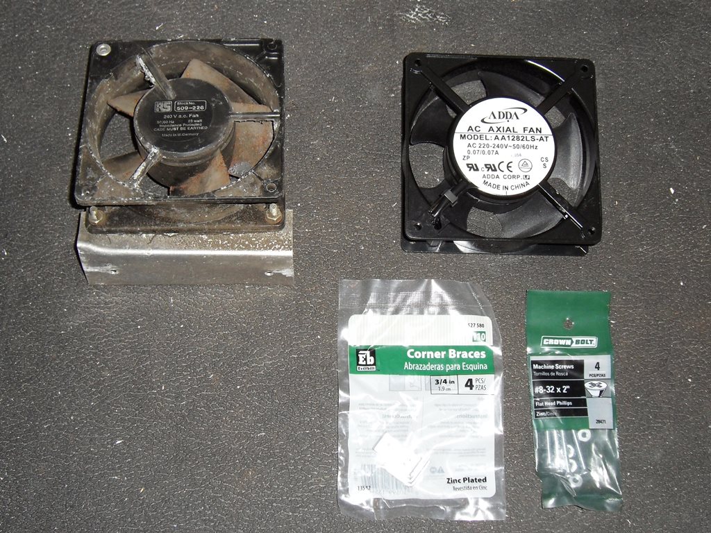
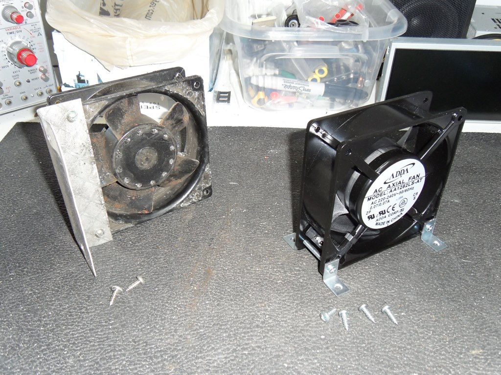
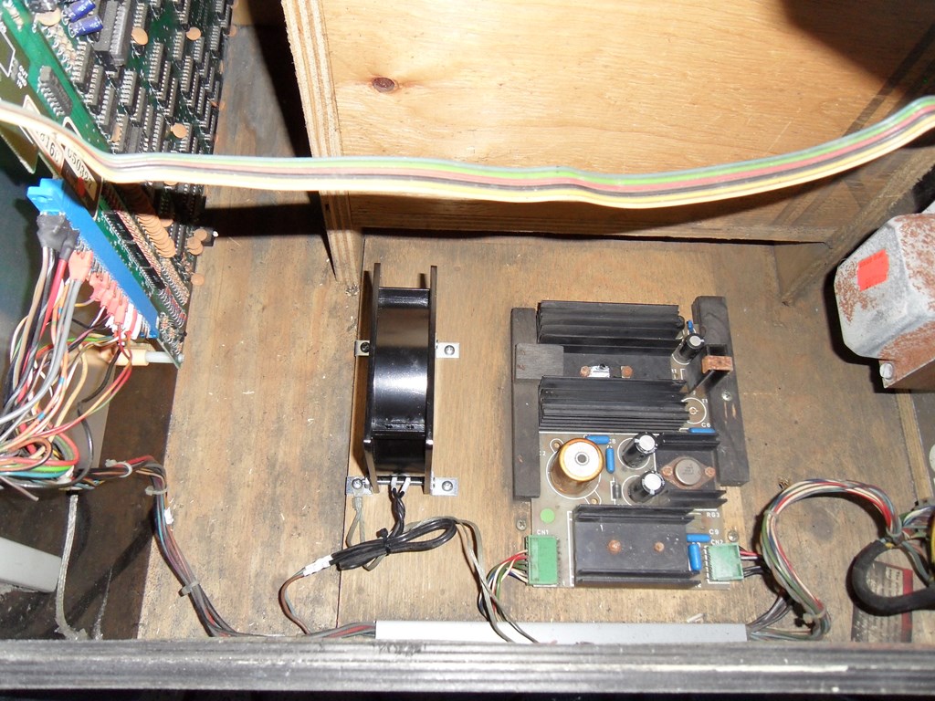
The original fan had already been replaced with a "modern" PC style fan that now too was in need of replacement (rusting, rattling and scraping). The replacement is a standard size 120mmx120mmx38mm 220V-240V 50/60Hz, in this case an ADDA AA1282LS-AT low speed/low noise variation off eBay. The brackets and screws are standard hardware from Home Depot.
|
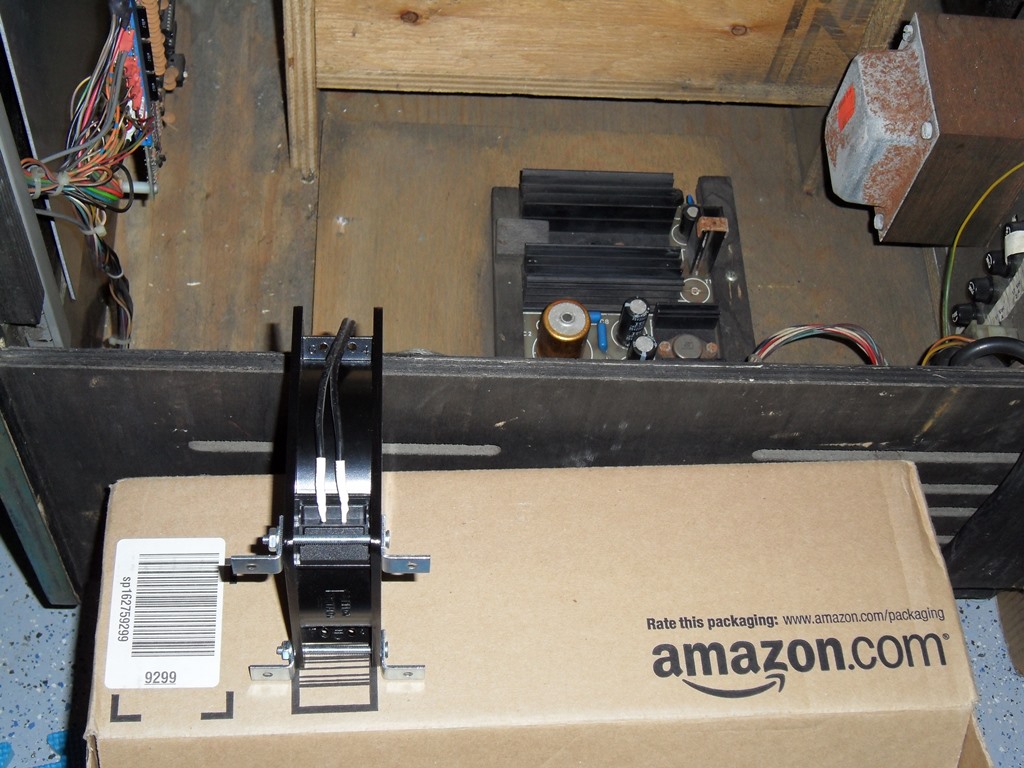
The prior replacement had removed the fan connector so this fan is directly wired. The fan worked fine with no monitor interference and not too much background noise. Hopefully this will help prolong the life of the electronics. I've ordered five more for other cabs, this time ADDA AA1282DB-AT that's quieter, lower power and a longer lifespan ball fan (versus the cheaper sleeve fans).
|
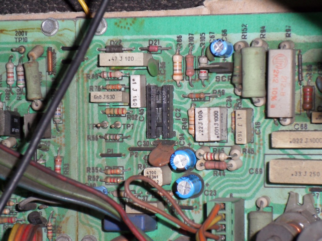
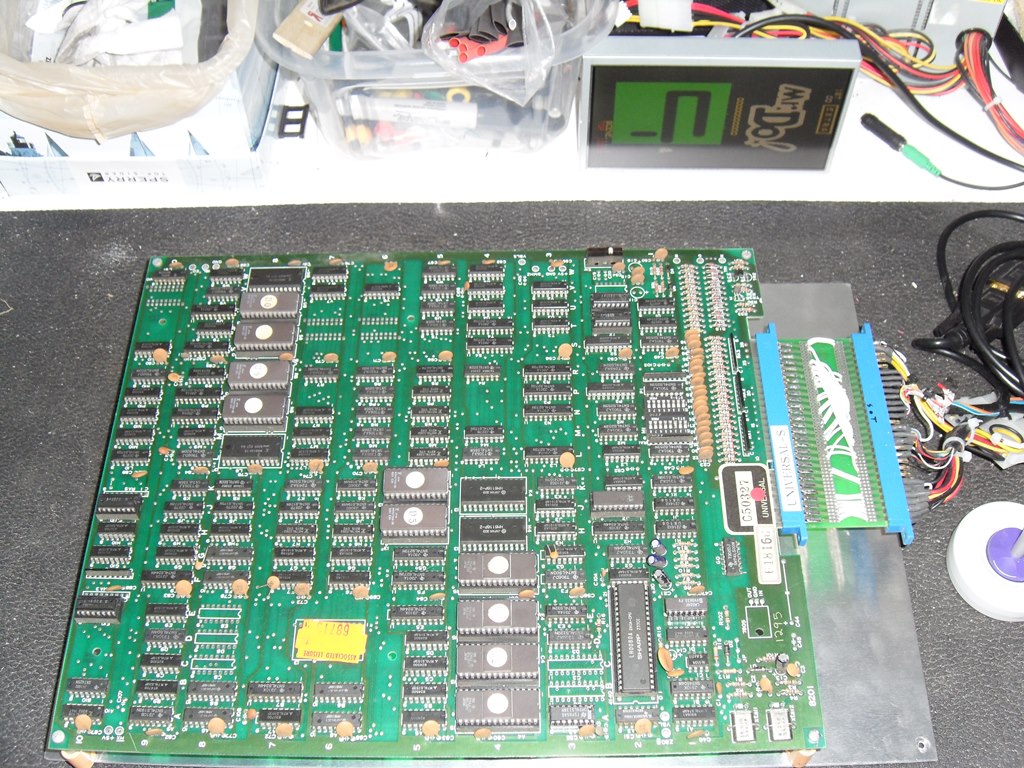
The game PCB developed a graphics fault where the sprites were missing and horizontal coloured lines flashed across the screen. The flashing lines were even present on the static credit screen. Diving in with a scope on the sprite RAM (F8, 6148) showed that scoping the D-bus made the lines much worse and sticky on screen. The ~WE line was flickering all over the place. Tracing that to H8 (LS157) pin 13 as a flashing high/clock, then to C9 (LS10) pin 4 flashing, then to J7 (LS157) pin 10 & 12 flashing and then to a floating pin 9 that's supposed to be a CLK input. That led to J9 (LS174) with all outputs floating. Comparing with J8 (LS175) that's performing the same function on other bits of the bus that was outputting fine suggested J9 (LS174) was dead as a dodo.


|
With the outputs all dead on J9 a piggyback on J9 brought back the sprites and confirmed the suspected fault. Replacing J9 (LS174) fixed the game :)

|
Rather than continuing to use Bob Roberts MTC-900E kits with extras added and a bunch left over I decided to make up some MTC-900 specific kits based off the Panasonic M5 series caps from Digikey. Plus, I only have two 900E kits left and I'd rather use those for MTC-900E's in future to save ordering more. In total I made 25 sets that should be about enough for all the spare and in-cab MTC-900 chassis I have.
|
Having based the MTC-900 kits on the two usual chassis, part way through fitting the kit to the ITT chassis in the Mr. Do! I discovered that it doesn't use a "DS" series deflection board but a "DB1" deflection board. This variation appears to be close to an MTC-900E deflection board except still using the MTC-900 LOPT and "S4" neck board. Unlike the "DS" series based on the TDA 1470 vertical deflection IC the "DB1" uses the TDA 2653A like the MTC-900E chassis. Below is the cap list for this chassis (still also with the usual MTC-900 "IS" interface board).
| IS 50142230 | DB1 50142800 | ||||||
|---|---|---|---|---|---|---|---|
| Location | Original | Manual | Kit | Location | Original | Manual | Kit |
| C65 | 4.7uF 250V |
4.7uF 250V |
4.7uF 250V |
C66 | 2.2uF 63V |
2.2uF 63V |
2.2uF 160V |
| C18 | 22uF 25V |
22uF 16V |
22uF 63V |
C23 | 100uF 25V |
100uF 16V |
100uF 50V |
| C17 | 10uF 25V |
10uF 16V |
10uF 25V |
C94 | 100uF 25V |
100uF 16V |
100uF 50V |
| C53 | 22uF 25V |
22uF 16V |
22uF 63V |
C85 | 100uF 25V |
100uF 25V |
100uF 50V |
| C8 | 10uF 25V |
10uF 16V |
10uF 25V |
C60 | 2200uF 16V |
2200uF 16V (E) |
2200uF 25V (not in kit) |
| C9 | 10uF 25V |
10uF 16V |
10uF 25V |
C31 | 1000uF 35V |
1000uF 35V |
1000uF 50V |
| C10 | 10uF 25V |
10uF 16V |
10uF 25V |
C72 | 47uF 250V |
47uF 200V |
47uF 250V |
| . | . | . | . | C97 | 47uF 250V |
47uF 200V |
47uF 250V |
| . | . | . | . | C33 | 1000uF 35V |
1000uF 35V (E) |
1000uF 50V (DS C60) |
| . | . | . | . | C55 | 22uF 16V |
22uF 16V |
22uF 63V |
| . | . | . | . | C40 | 4.7uF 50V |
4.7uF 16V |
4.7uF 50V |
| . | . | . | . | C98 | 100uF 25V |
100uF 16V (E) |
100uF 50V (DS C33) |
| . | . | . | . | C32 | 2.2uF 63V |
2.2uF 63V (E) |
2.2uF 160V (not in kit) |
(E) in the table denotes the value specified for the capacitor in the 900E manual for the "DE" deflection board. The extra caps I had already left over from 900E kits used on 900's.
|
After a new fan, alternate chassis, chassis repair, cap kit and board repair the machine is ready, again, for the next show.