
|
|
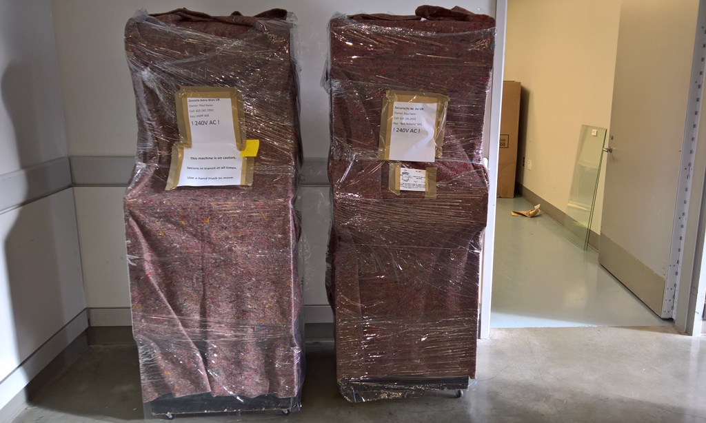
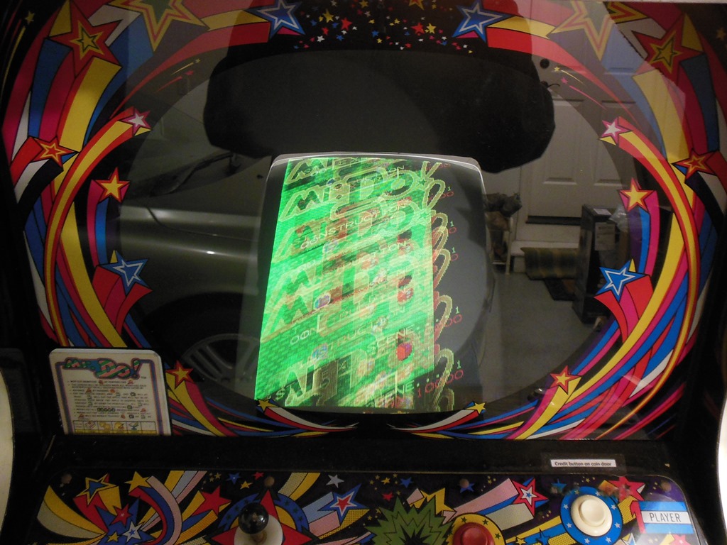
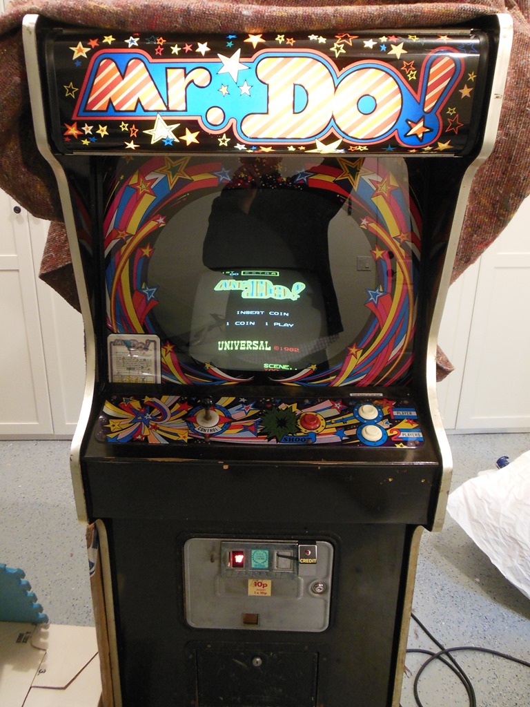
Though the monitor was dim the game was running OK during Thursdays setup but alas it didn't survive into Friday. The game board stopped booting. With no spares to hand it was wheeled into the backroom and wrapped for return :(
|
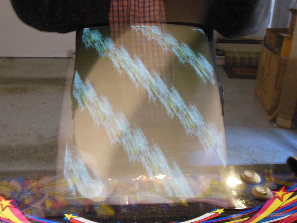
Back at home the game had the same issues as at the show - dim monitor and a none-booting game board - but also now had intermittent video sync loss.


|
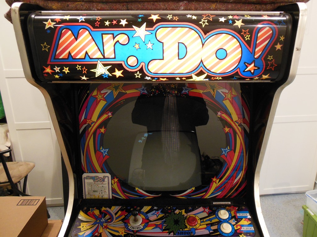
I'd had problems with the CRT in this game before and had previously unsuccessfully attempted to investigate with the rejuvenator. A fellow collector had looked at my rejuvenator & adaptors afterwards and had determined that the unit was working properly but there was a wiring error on my custom made CR-24 socket adaptor that he fixed such that it was all now working properly. The CRT had continued to deteriorate over the last few years (getting dimmer and taking longer to come up in focus) so it was time to have another attempt at rejuvenation or replace the monitor.
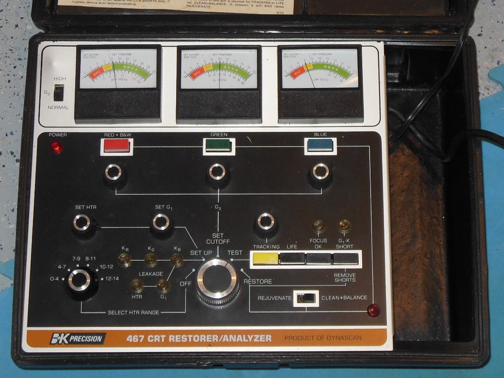
Setting up the rejuvenator revealed that the blue gun was in the yellow marginal zone and that there was a G1-K short. Using the remove option created some disconcerting flashes in the neck of the CRT but after a couple of shots the G1-K short light was out. Retesting the colour balance now had all three guns in the good zone. After reconnecting the chassis and retesting the picture came up bright and in focus straight away and looked good!
|
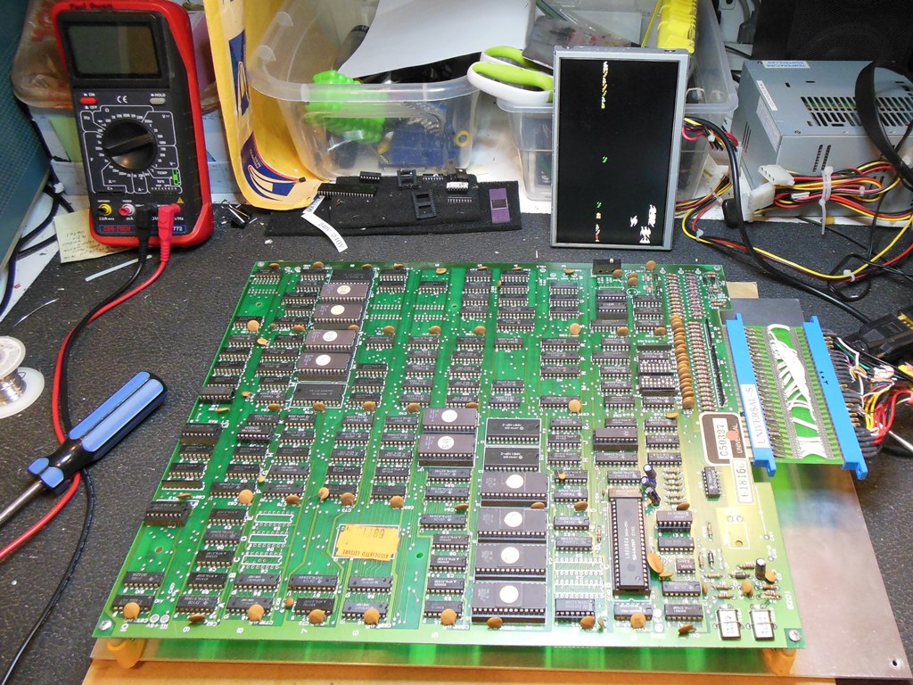
The game showed no signs of booting - all Z80 CPU address & data were idle high. The Z80 CPU clock pin 6 was running and reset pin 26 was high and toggled OK on power cycle. The interrupt on pin 16 was also running. Replacing the Z80 CPU brought the game back to life but with sprites not working properly.
The game sprites were misplaced in half of the screen, as in when sprites appeared in lower half of the screen they were positioned correctly but when they should have been in the upper half they'd wrap back into the lower half. It appeared as if a horizontal sprite address bit was stuck. Checking the address/count multiplexors A5 through D5 (LS153) found IC A5 pins 10 & 11 stuck low. IC A7 (LS393) pin 10 was low and pin 11 active. I considered a bad IC A7 (LS393) but a check with a comparator didn't flag any issue. Comparing with a second Mr. Do! game PCB confirmed that IC A7 pin 10 was also low and therefore expected.
Poking around with a scope found IC H6 (LS283) pin 11 RB7 looking suspicious "--|--|--|--|--" and pin 12 running like a clock. A comparator confirmed no issues with IC's A5,B5,C5 and D5 (LS153). A video probe showed that the outputs of A5 -> D5 showed the issue of half screen activity. Inspecting IC B7 (LS244) with a scope didn't find any obvious problem.
Comparing with the second good PCB confirmed C5 & A5 showed full screen activity on the good board and half screen activity on the bad. This suggested that possibly this was as a result of a read from IC's A8/B8 (6148). Similarly, the sum output of IC H7 (LS283) was also all one side on the bad board but full screen on the good. It was time to try and check the output of the sprite RAM, RB7 data as latched via signals LA1, LA2, LA3, etc. IC G6 & F6 (LS161) pin 6 was idle & partly floating, completely floating on the title screen. Shorting RB6 to RB7 moved the characters to one corner of the screen. Shorting RB7 to IC G6 pin 8 removed the artifacts from the title screen and I suspected that IC B6 (6148) was bad. Trying a piggyback of a compatible 2148 on IC B6 fixed the sprites and replacing it fixed the game.
|
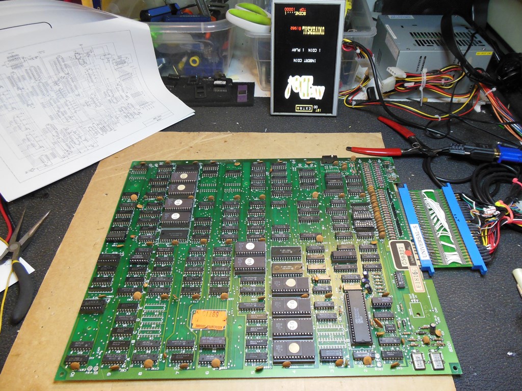
This board was earmarked to become a spare board for the game. It seemed to be generally working but had a no video sync problem. Looking at the sync output on the scope found the sync output less than 2V amplitude. Comparing with the other board, it had ~4V amplitude and thus I suspected a bad IC K9 (LS86). Replacing IC K9 fixed the video sync and the board had no further issues.
|
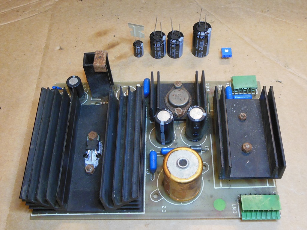
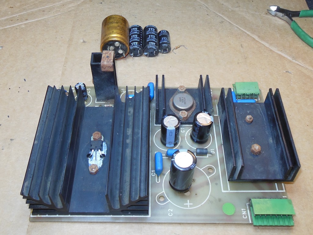
There was a lot of audio hum from the speaker and some bands on the picture that I suspected was failing capacitors on the regulator board. Pressing on one of the two +12V smoothing capacitors on the regulator board noticeably changed the hum so I removed the regulator board to a apply cap kit on it. With new caps, the audio hum was much reduced and bands in the picture were gone. No change to the sync loss problem, however.
|
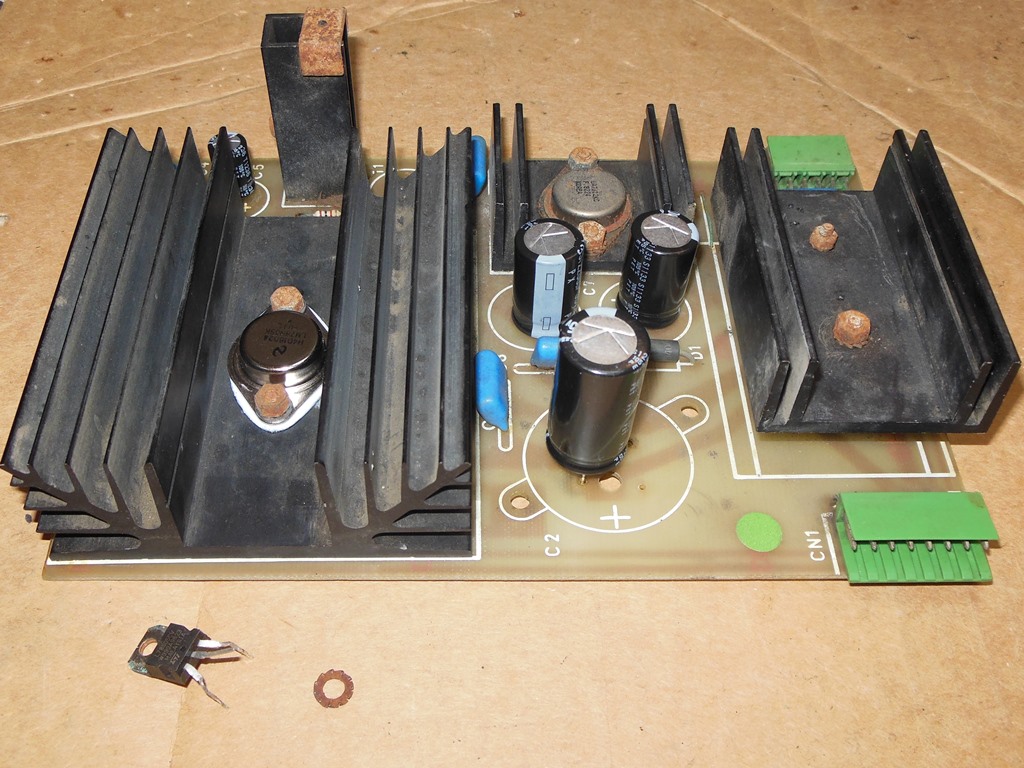
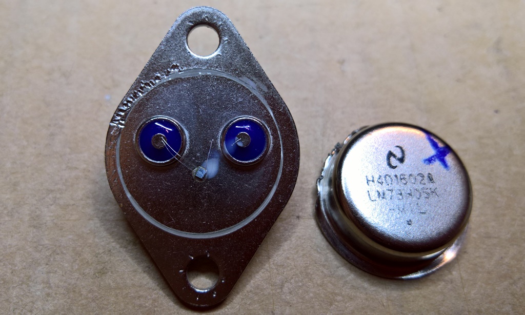
Whilst the regulator board was on the bench I noticed that the uA78H05 TO-3 regulator had been replaced with a TO-220 one. The heat sink residue and lack of insulation on the legs stretched perilously close the heat sink suggested that this was prior repair. I ordered a pack of LM78H05K's to restore the board to back to its original configuration, but the first one fitted yielded no +5V output. Testing back on the bench found the LM78H05 was not working. Fitting a second LM78H05K yielded the same result - dead, no output. Before I fitted the third one I tested it on the bench to make sure it was working - 12V DC input yielded +5V output as expected. After two failures on what was a known working board I was suspicious of the LM78H05K I had bought from China.
|
To confirm my suspicions I opened up one of the blown LM78H05 and discovered that it was indeed fake. The construction looked like it was a small 78L05-type die bonded with thin wires to the TO-3 can. There was no way this design was rated at 5A capacity - more like 100mA. A case filed with eBay with this picture as evidence resulted in a full refund and I went ahead and ordered a pack of uA78H05 with a 1982 date code.

|
With the uA78H05 fitted the game powered on OK and ran for a few hours without any power issues.

|
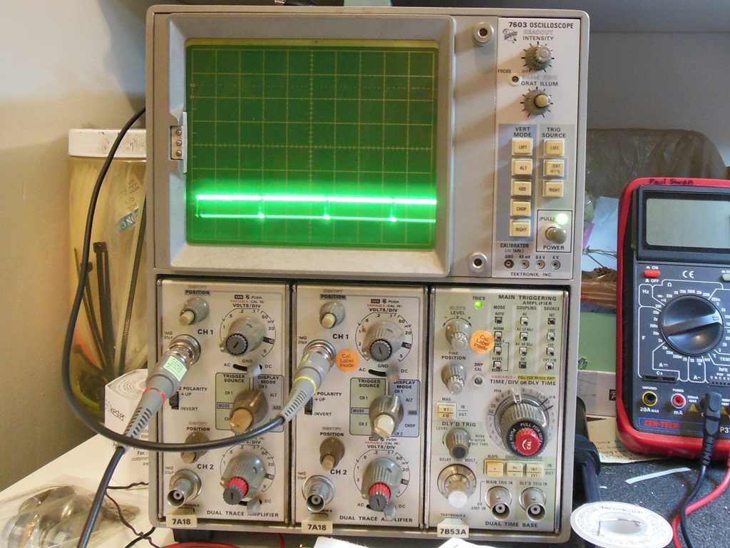
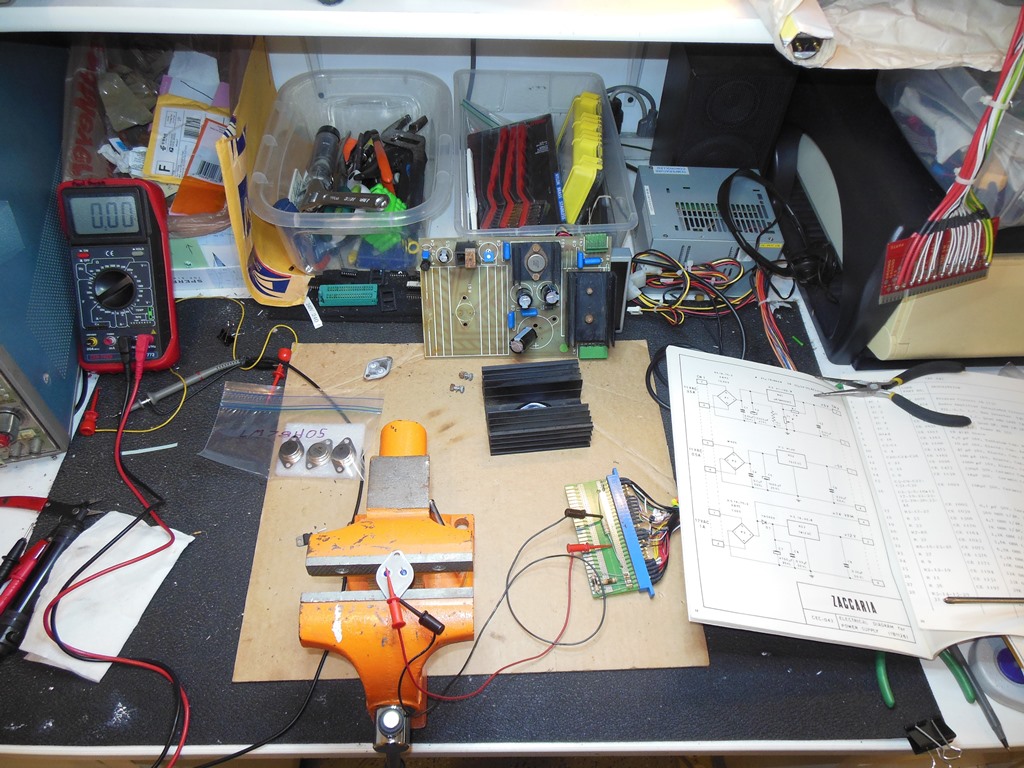
On the bench the monitor chassis exhibited the same problem of being very sensitive to sync adjustment - it was difficult to lock and would lose lock that needed a tweak to bring it back on. Checking waveform (1) from the manual, the output from TR1 (BC237), found it not matching the manual. I suspected a bad TR1 (BC237) and replacing it fixed the sync issues.


|
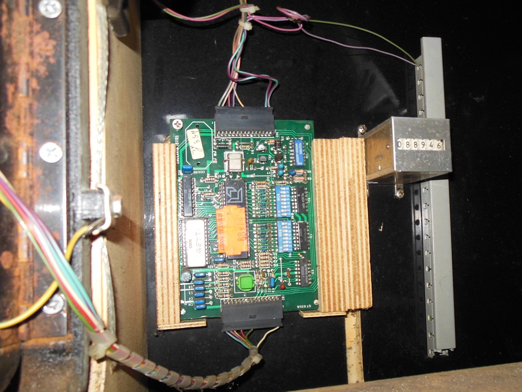
The game was working properly but each coin yielded five credits. All my games are set for 1 coin 1 credit so I checked the credit board DIP switches to verify if they had been changed at the show. The DIP switches were set correctly so I suspected a fault on the credit PCB. After removing the credit board and setting it up on the bench I began to look at IC 1 (40097) on the scope. Pin 1 ~RD looked OK and the input pins 2, 4, 6 & 10 all seemed reasonable. I set up the scope for 2-channels to be able to trigger on 8035 CPU read and see the data being read out. With that I found pins 3, 5 & 7 returning high or low OK but pin 9 (DB3) returned high or floating. Replacing IC1 (40097) fixed the credit board.
This game set a record for most components repaired in a single session on one game with the CRT, game board, power board, monitor chassis and credit board all needing repairs.