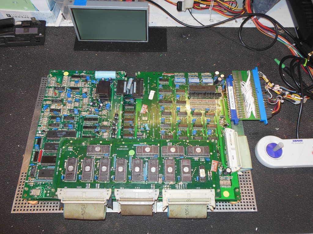
This game PCB was from a dedicated Jackrabbit upright discovered in a warehouse on the east side of the US. The reported problem was that the game PCB was dead with no video but with a sound board chime on power up.
|
|
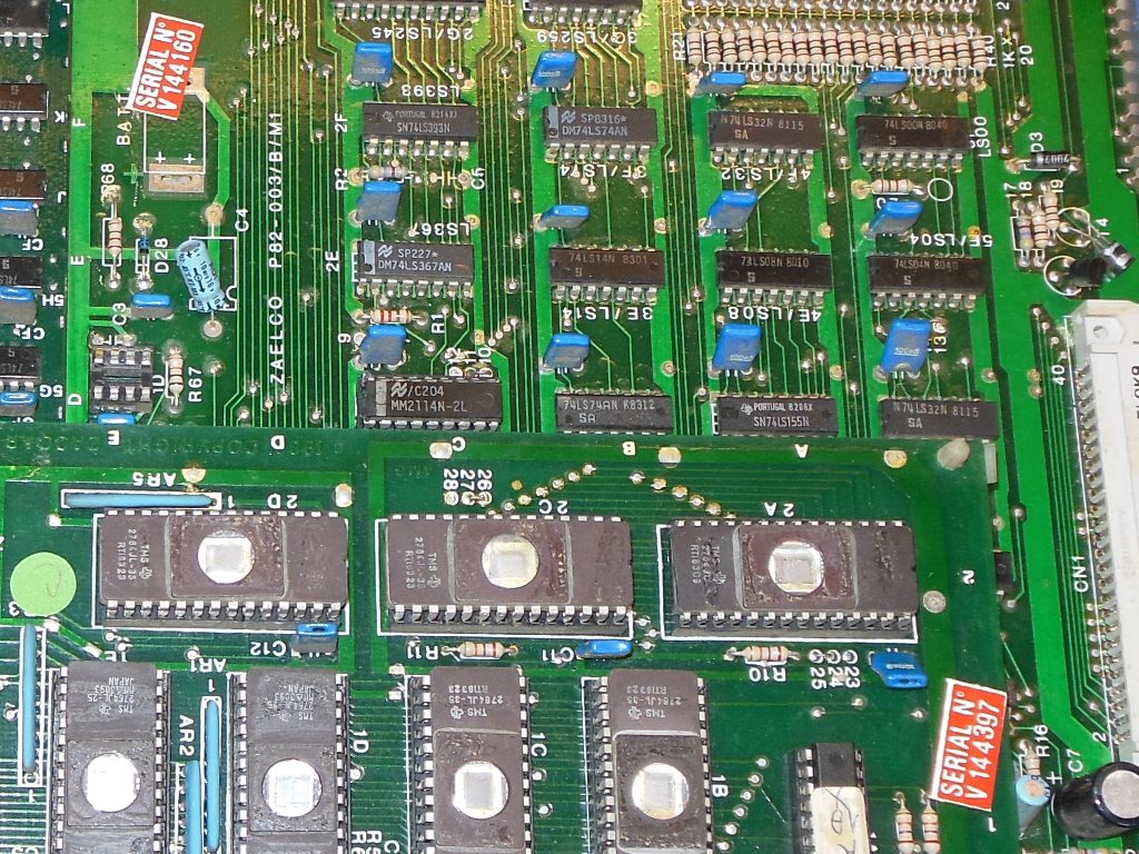
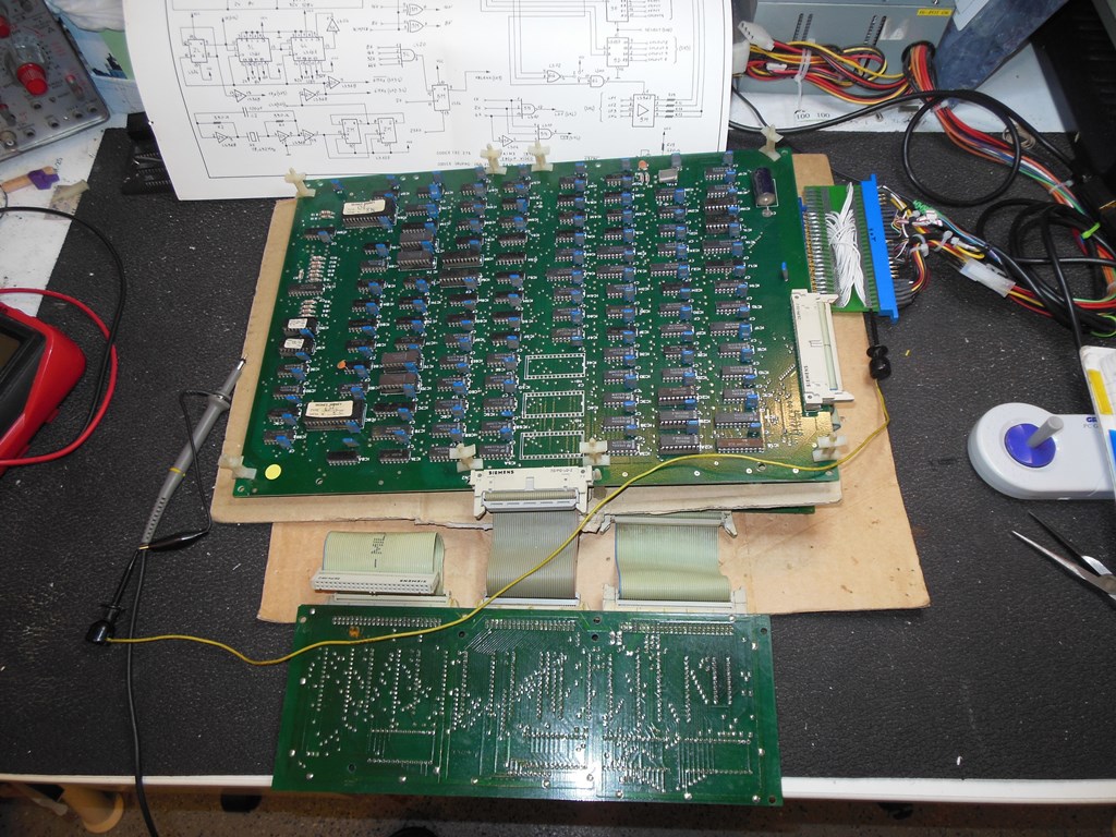
The owners description was pretty accurate - the sound board chimed on power up but there was no video output or response to coin input. The board had two serial numbers, V144160 on the CPU board and V144397 on the ROM board. There were also some burn marks near the power input connector suggesting that the edge connector (board and/or cabinet) maybe dirty and thus overheating.
|
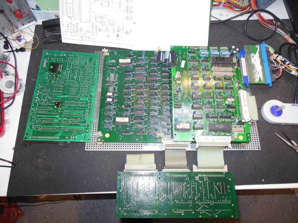
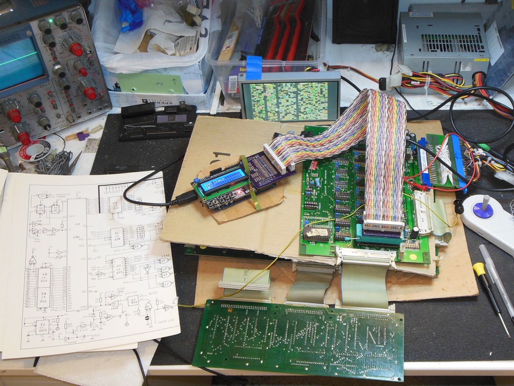
Starting at the main Z80 CPU and poking around with the scope indicated that the CPU was running and the clock on pin 6 looked good. The reset line was inactive and there was no watchdog firing. Since the game was clearly not running the lack of a watchdog seemed suspicious so I investigated the watchdog circuit and discovered that the VBLANK signal on pin 13 of 2F (LS393) was stuck low (and thus the watchdog counter wasn't running to fire the watchdog). VBLANK originates on the video PCB that in order to get good access to needs to board stack pulling apart and reassembling in a way to leave the video board on the top. The sound board could be left out for now.
|
Tracing VBLANK back on the video board revealed that pins 11/12 of 5P (LS74) were idle indicating that the video clocks were not running. The 6MHz clock was present on pin 11 of 2N (LS368) OK. The video counters 3N & 4N (LS161) were all idle with no clock on pin 2. Inspecting 5M (LS74) showed pin 2 high (bad), pin 3 active. Inspecting 5J (LS00) showed pin 6 high (bad), pins 4 & 5 active. Inspecting 4L (LS161) showed that pins 14,13,12,11 were not divided down as they are usually. I suspected 4L was bad.
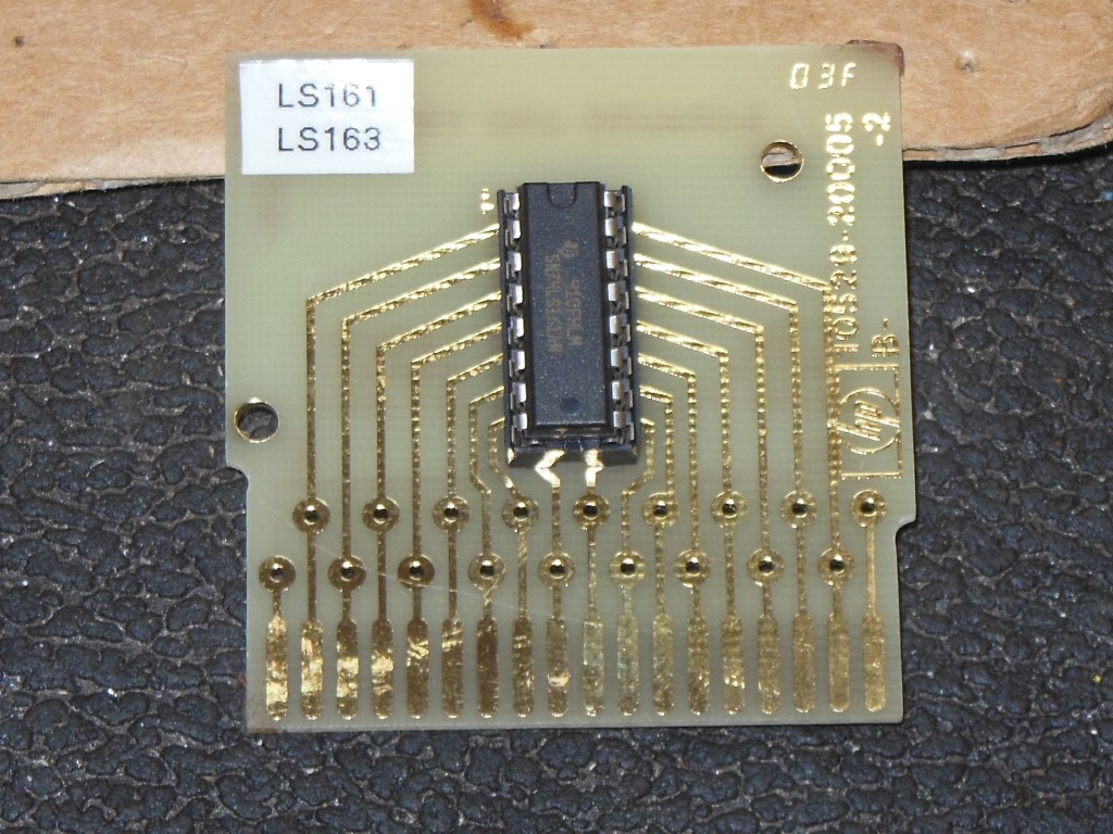
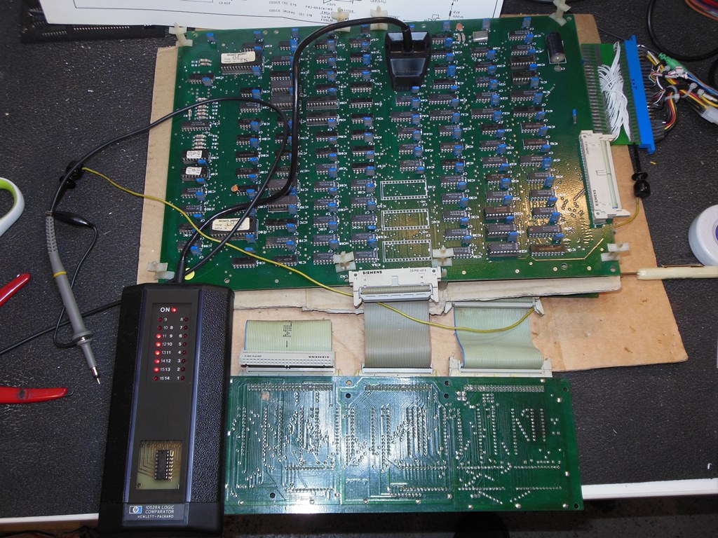
After a recent run of bad LS161's on various boards I decided to try out an HP10529A comparator and make up an LS161/LS163 compare card for it. The comparator flagged 4L as bad on all its outputs.
Also note the Money Money labels on the PROMS on the video board - it's likely this board (and the whole cabinet) is a Jackrabbit conversion kit applied to a Money Money.

|
Replacing 4L (LS161) brought the video output back but the game was still not booting.
|
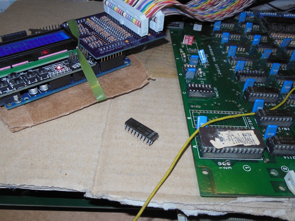
Rearranging the board stack to put the CPU board back on top and poking around with the scope revealed that the Z80 was being reset by the watchdog. Inserting the Arduino ICT and running the ROM test for set 1 flagged r1C, r1D, r2A as bad. Running the ROM test for set 2 flagged only r1C as bad. Reading the ROM r1C with the tester returned all FF. I suspected r1C (2764) was bad. Replacing r1C with one from my spare board allowed the ROM test to all pass, confirming r1C was bad.
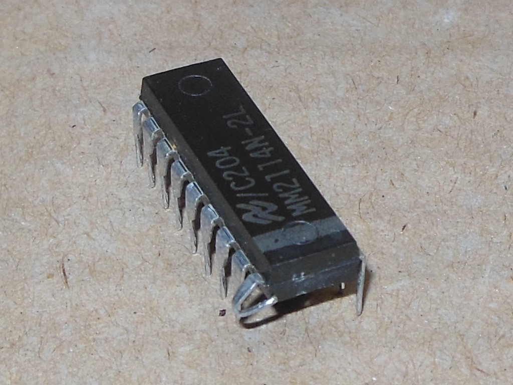
Moving on to the RAM test flagged RAM c2D (2114) as bad. Removing c2D revealed that it had a bent pin. Straightening out the bent pin and putting it back in the board was all that was needed to allow the RAM test to all pass.
|
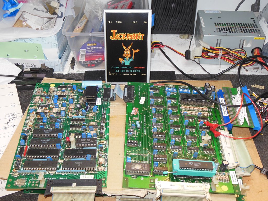
Reconnecting the sound board and reinstalling a Z80 brought the game fully back to life. Attention turned to the sound board and all the sounds & speech were working. As is common with this board set the speech for the rabbit was off - too slow on this board to properly lip sync with the rabbits mouth. There was also a burn mark in the center of the board to check out.

|
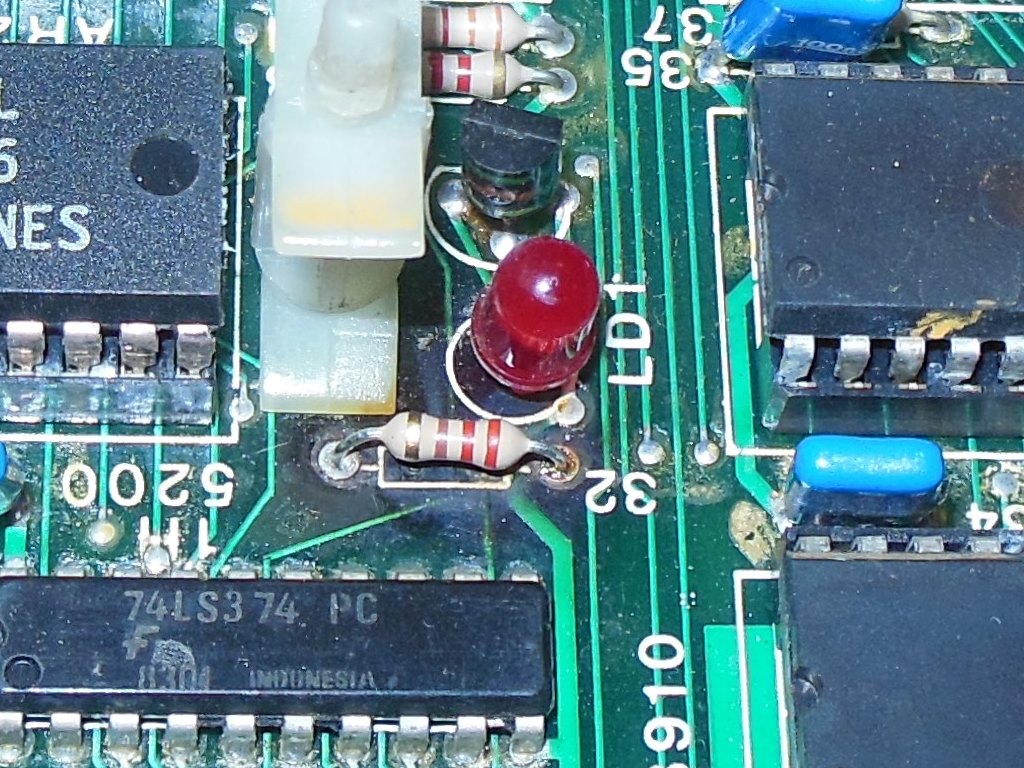
Investigating the burn mark revealed that R32, the sound board LED resistor, was burning hot. Measuring R32 in circuit gave 216 Ohms and removing the resistor confirmed that it was a 220R resistor. The schematics denote the value of this resistor as 470R. There was no indication it had ever been changed and it was likely that this was a factory manufacturing error. An Ohms law calculation for a 470R resistor and LED driven off the +12V supply suggested the power dissipation could exceed 0.25W, that is the usual standard sized resistor power rating, so I replaced R32 with 1K to be sure there was no further risk of burning.
|
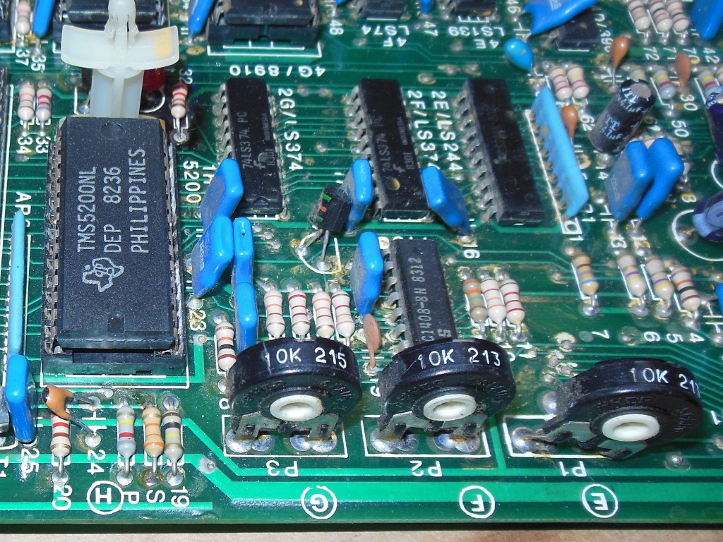
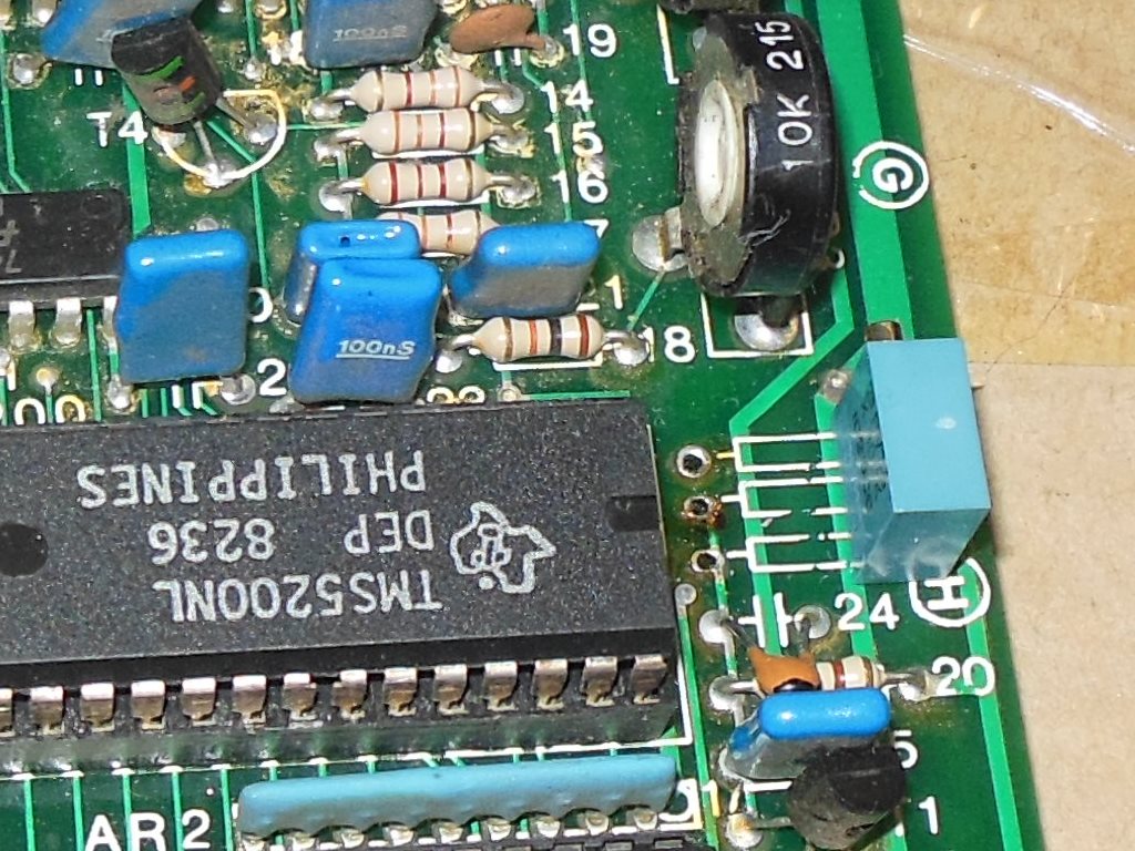
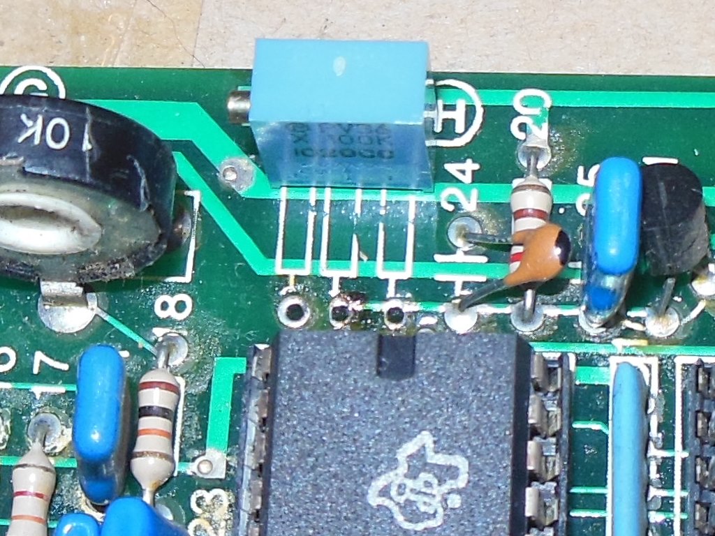
The speech for the rabbit looks to have been factory tuned using up to three resistors marked as R19, S & P. I've seen various resistor values fitted in these locations to attempt to set the speech speed to lip sync with the animation of the rabbits mouth. If the TMS5200 is replaced then the tuning usually needs recalibrating to the new IC fitted. Chances are it also varies with temperature and power supply voltage. The most effective way I've found to handle this design defect is to replace the fixed resistors with a 100K trimmer pot.
In addition to removing the resistors there is also a track cut that can be made to allow two tuning resistors instead of one. This had been done on this board and thus needed to be repaired so that the pot replacement would work properly. Tweaking the pot worked OK to fix the lip sync.
Three days of six hour burn in testing didn't result in any failures and the board was returned to its owner.