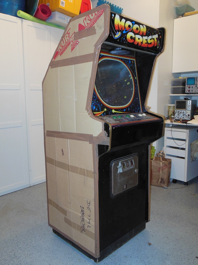

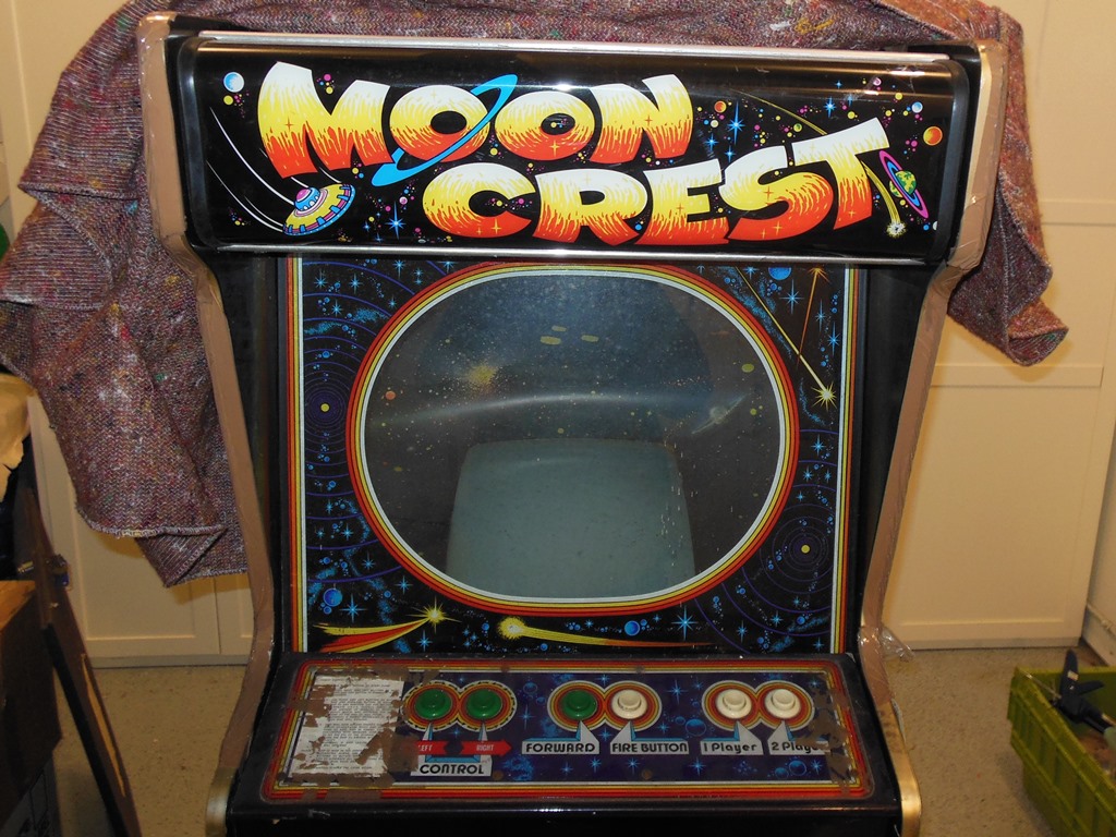
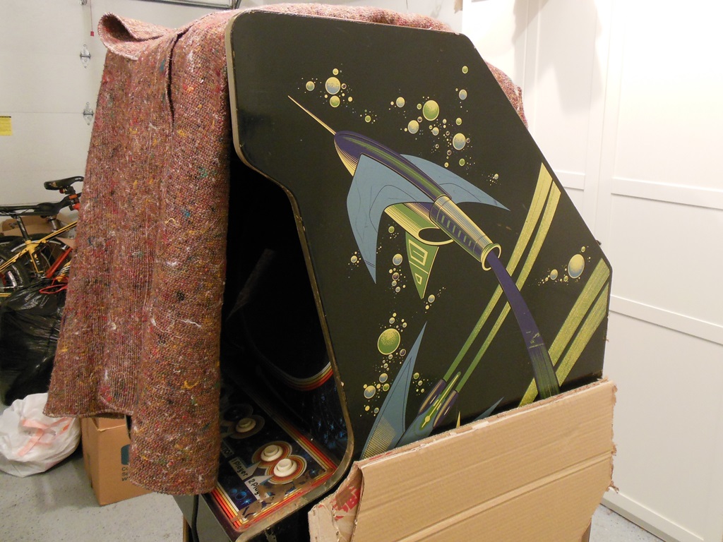
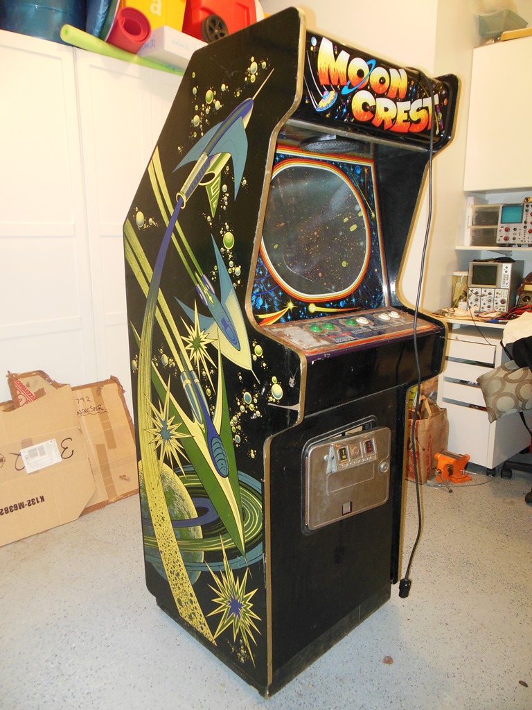
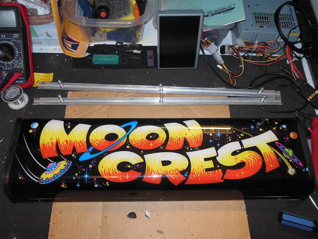
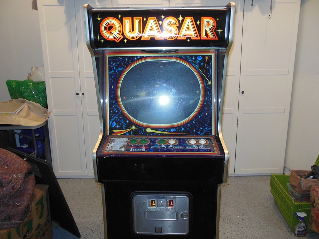
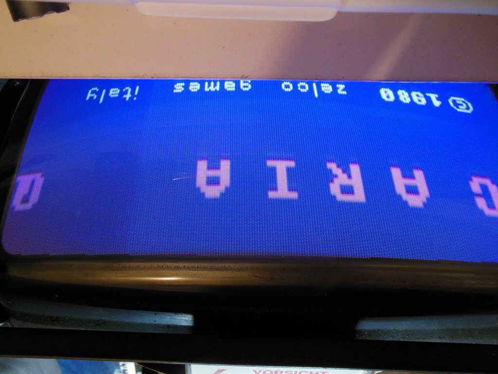
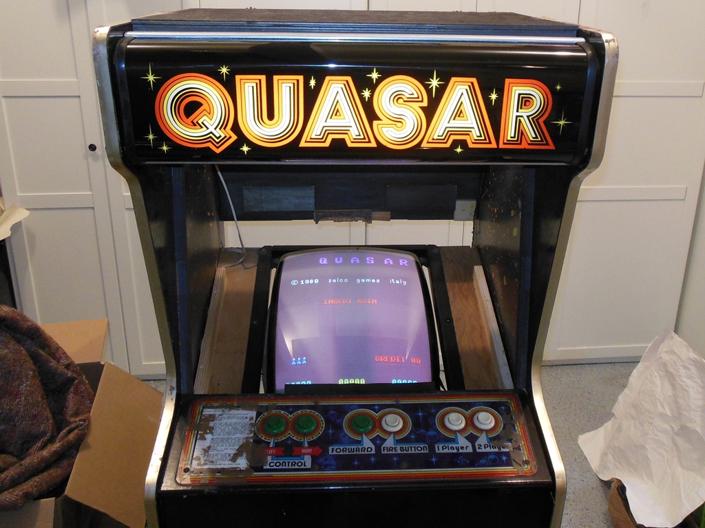
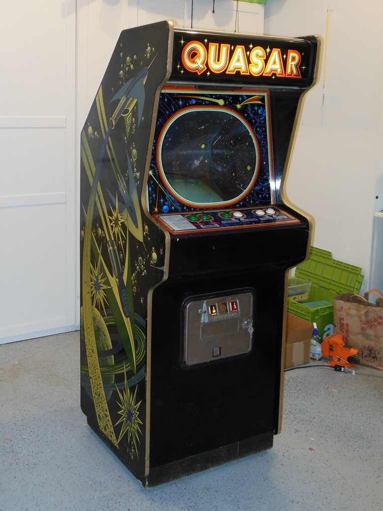
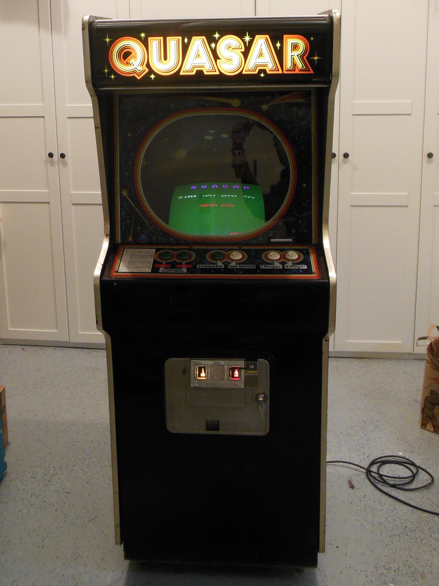
This game was listed for sale on eBay Germany in none-working condition. At first I thought it may be something unusual given the Moon Crest marque, atypical side art and Zaccaria game boards. Maybe it was something previously undiscovered (like a Zaccaria port of Moon Cresta in the same vain as Galaxia & Astro Wars for example). On arrival I discovered it to be a near complete factory Quasar with alternative side art :)
|
|
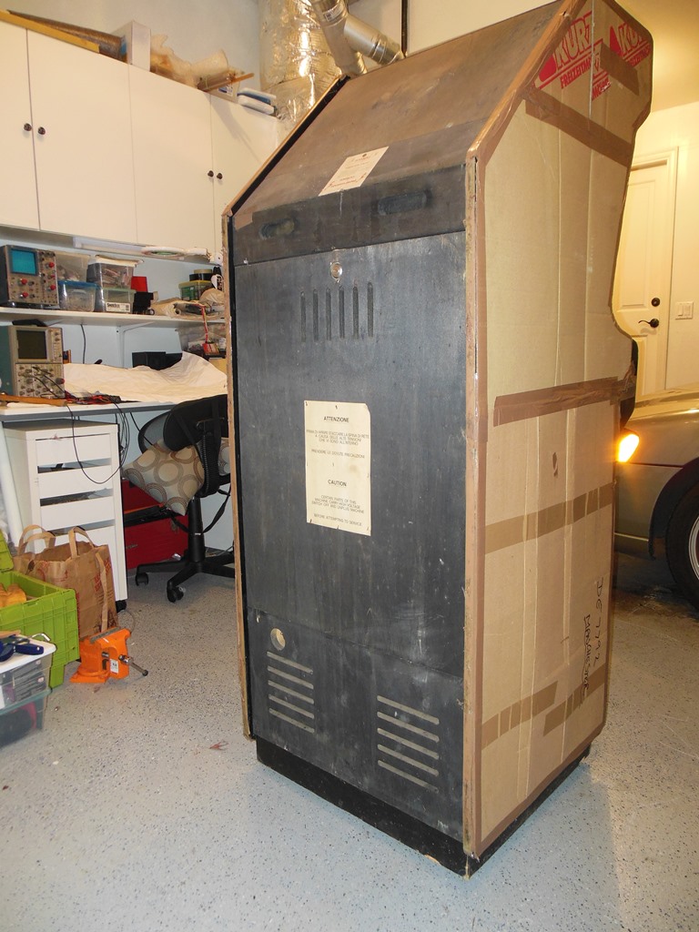
The exterior condition looked pretty good. The seller had protected the game with cardboard for shipping as I had asked originally but had used packing tape all the way around to secure. The tape removed from the control panel had left some residue behind. Portions of the T-molding were also afflicted with tape residue. The sides were still covered of course. The Moon Crest marque had some damage to the top right.
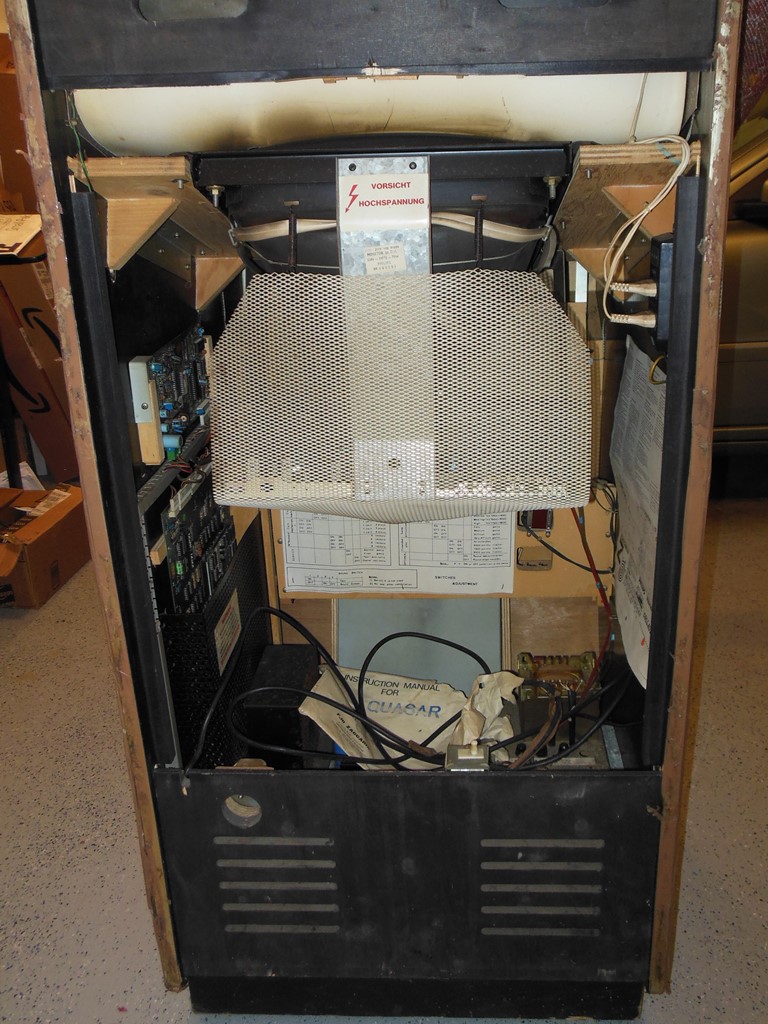
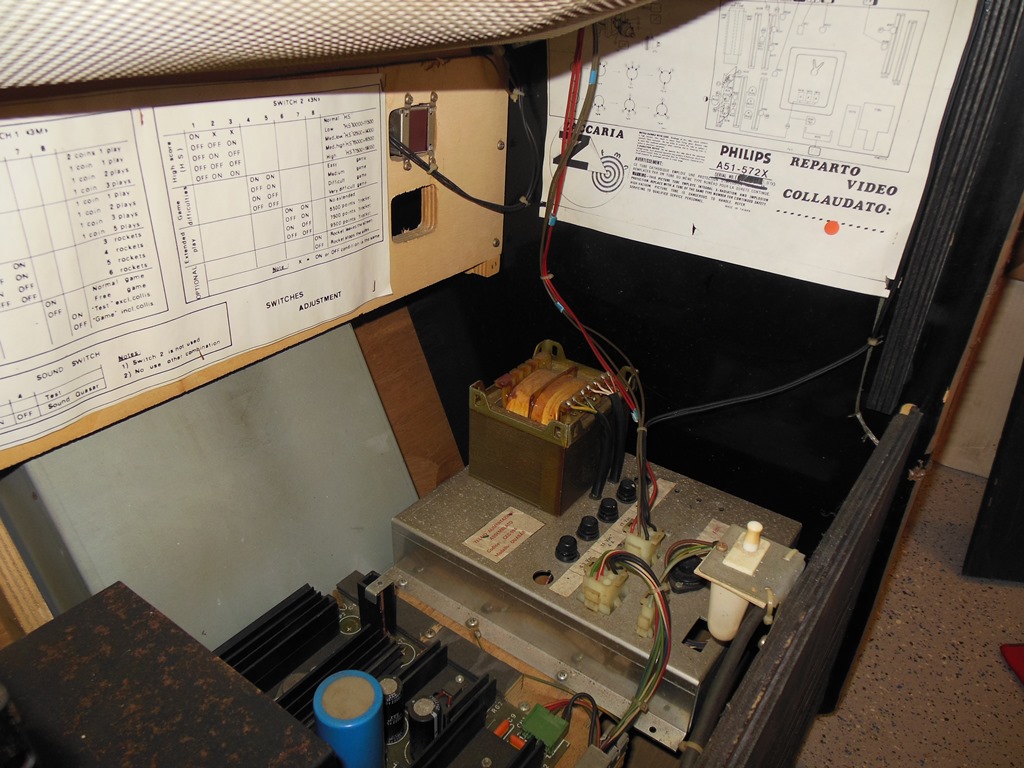
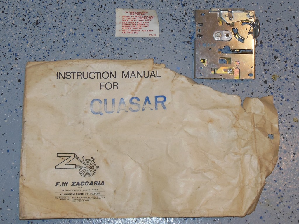
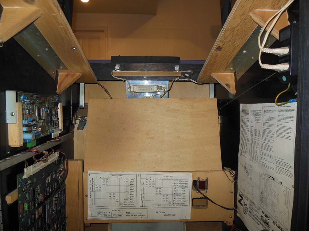
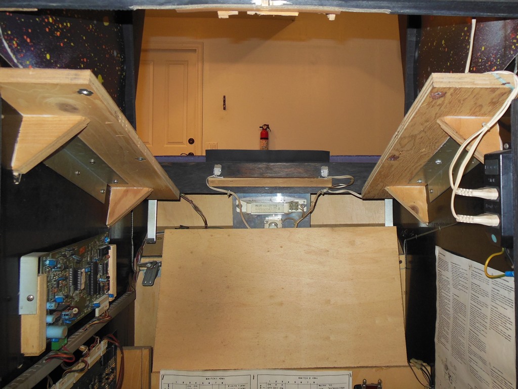
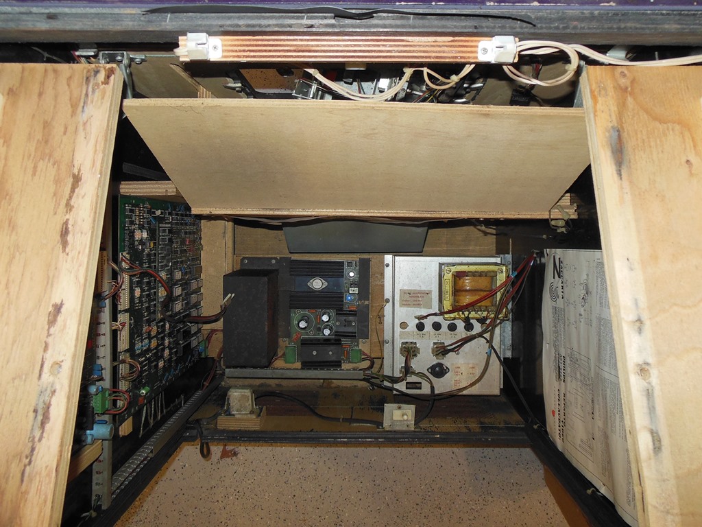
A first look at the inside found an empty Quasar manual envelope and all the major components (monitor chassis, power board, transformer brick and all game boards).
|
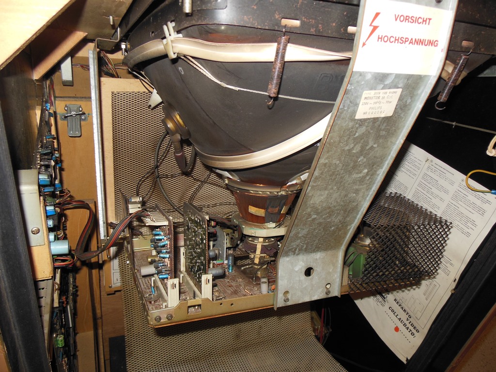
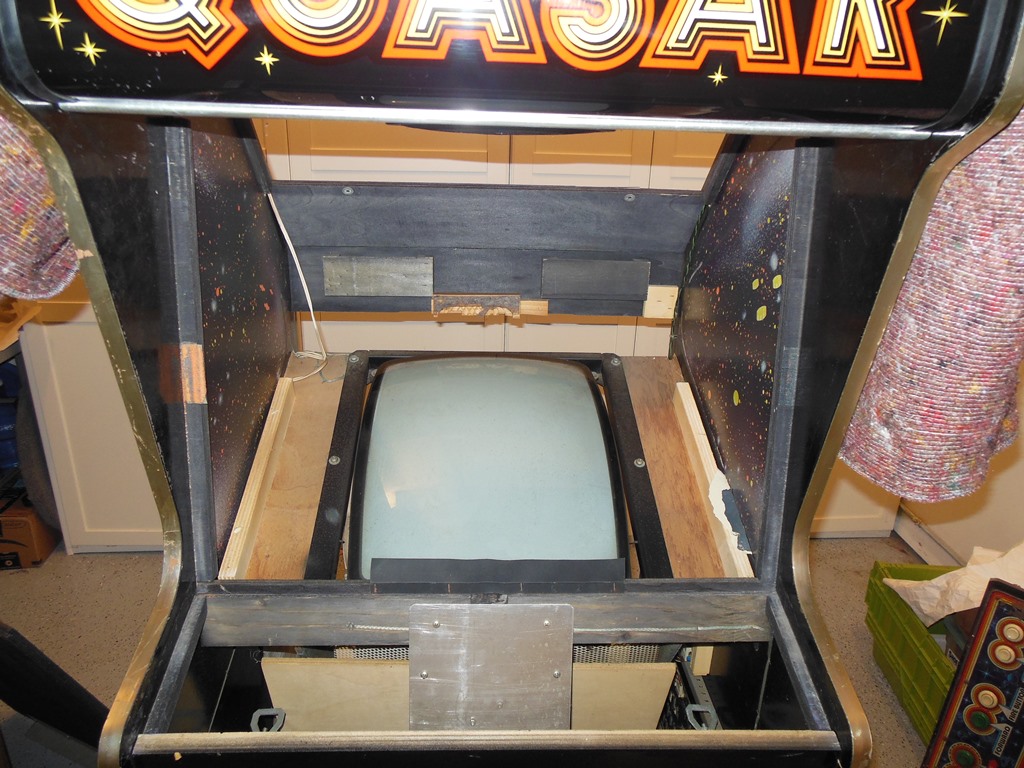
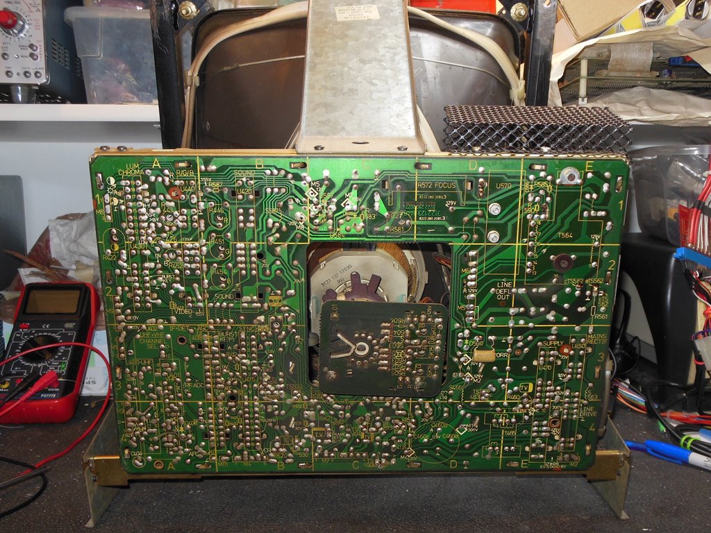
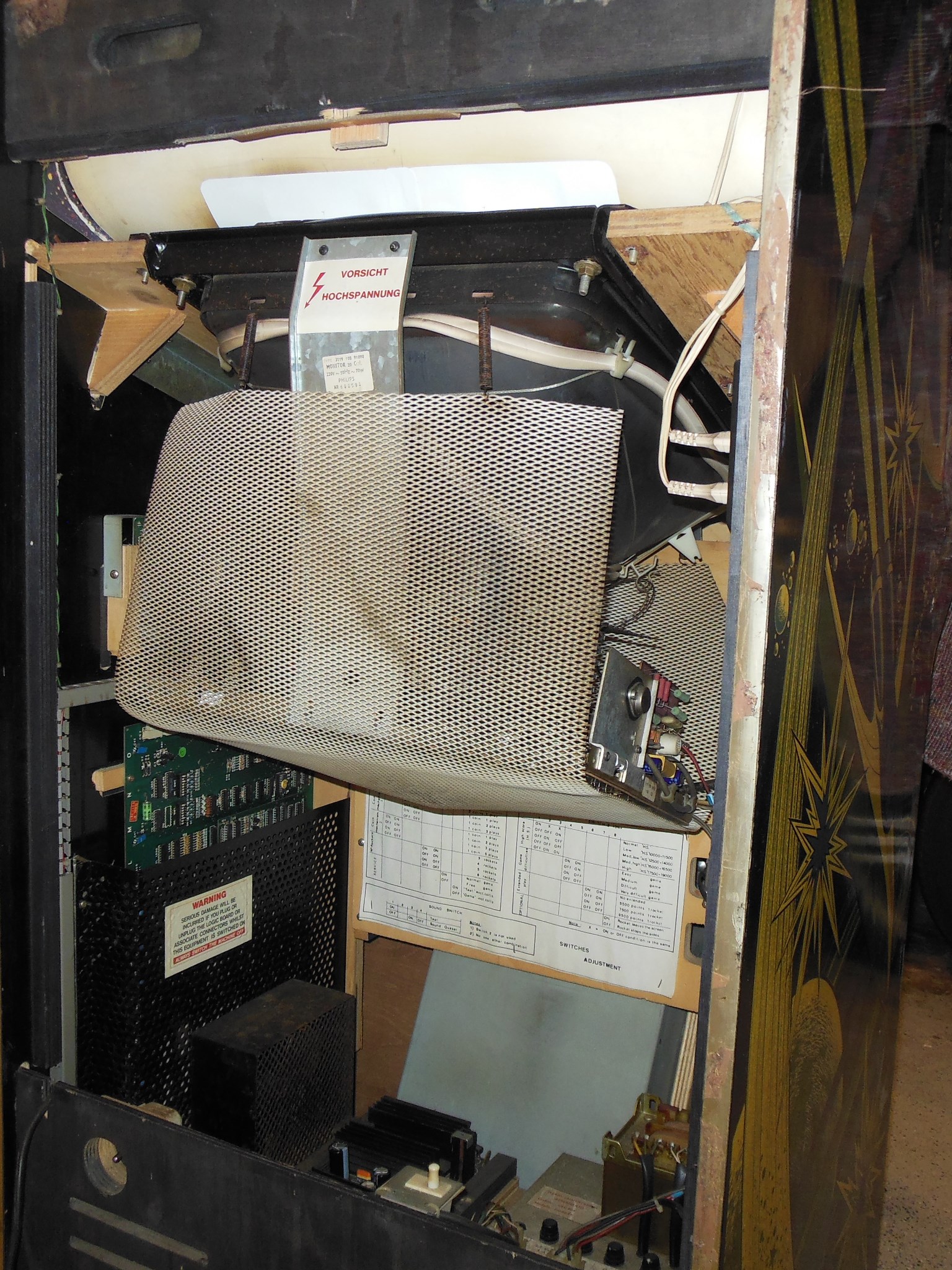
Un-clipping the monitors protective mesh revealed an original and complete Philips KT-3 monitor. Though it looks similar to the Hantarex MTC-90, aside from sharing a tripler based high voltage design and plug in card style it is otherwise completely different. The Philips KT-3 chassis is a depopulated TV chassis with the best service manual I've ever seen. The KT-3 based TV's are highly regarded in the vintage TV community, with many still in daily use. That said, I had last attempted to work on these chassis back in the UK in 2000 with limited success...
|
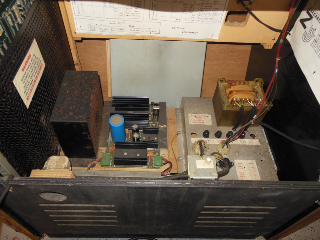
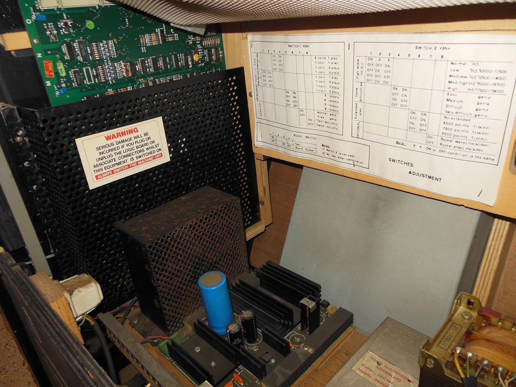
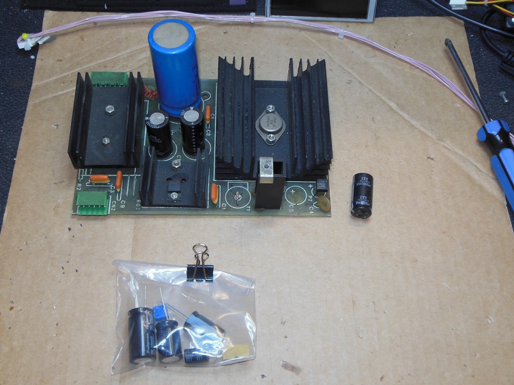
All the components of the power supply plinth were present, right down to the mounting hardware - the cover cage for the game PCB is often missing. The only thing I noticed was that one of the capacitors was missing from the 1B1126 regulator board that having rusted through and fallen off the board.

|
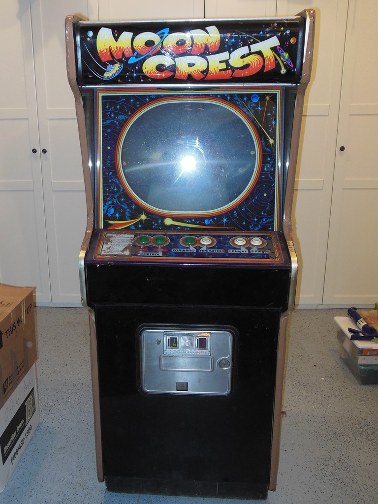
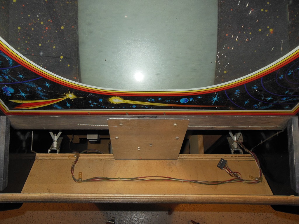
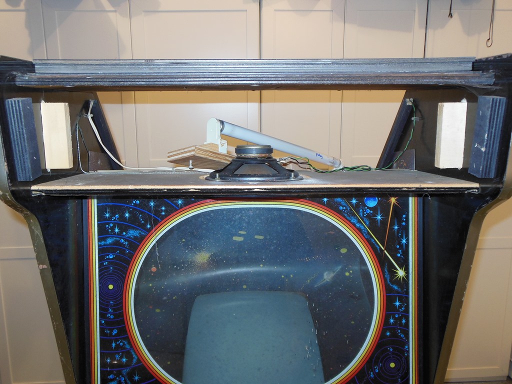
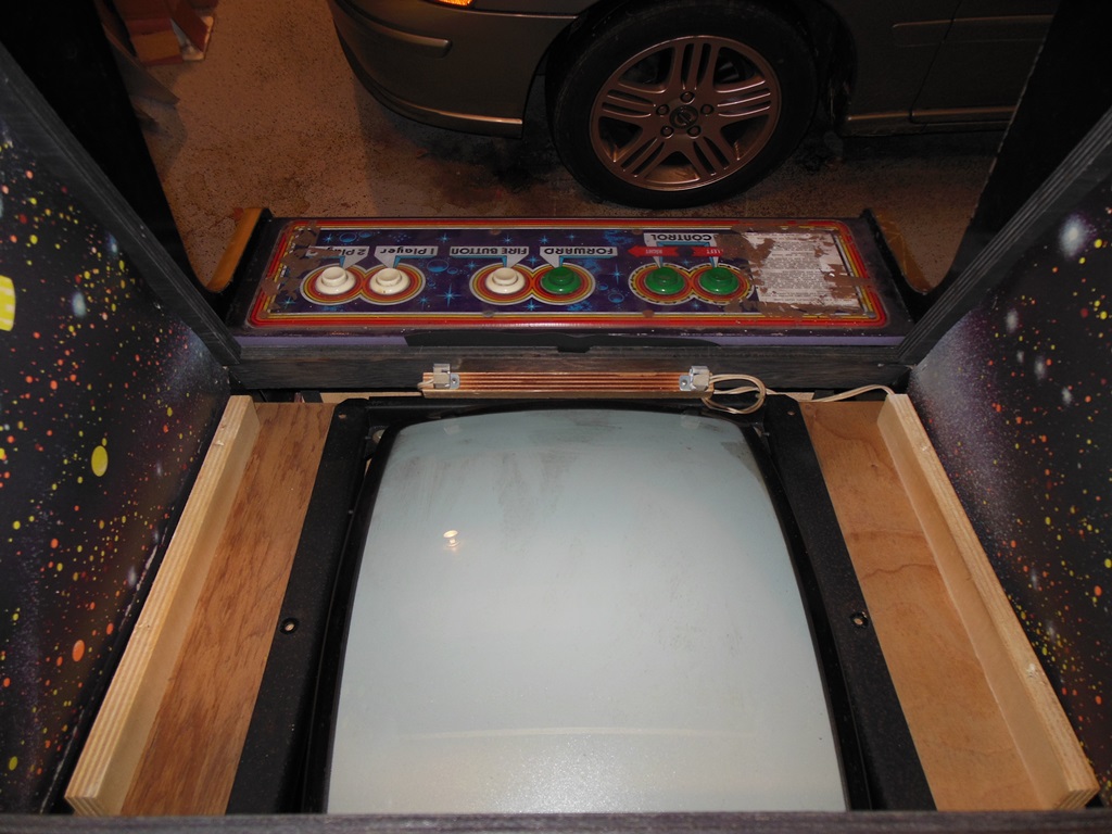
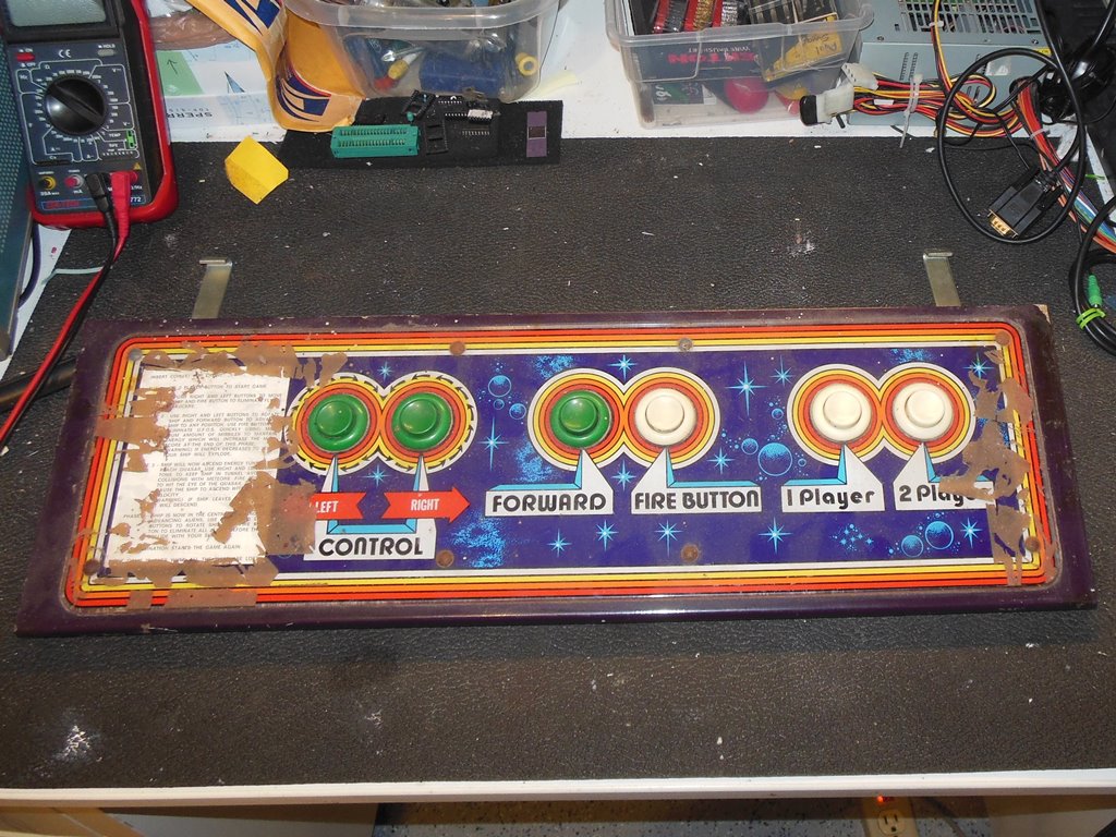
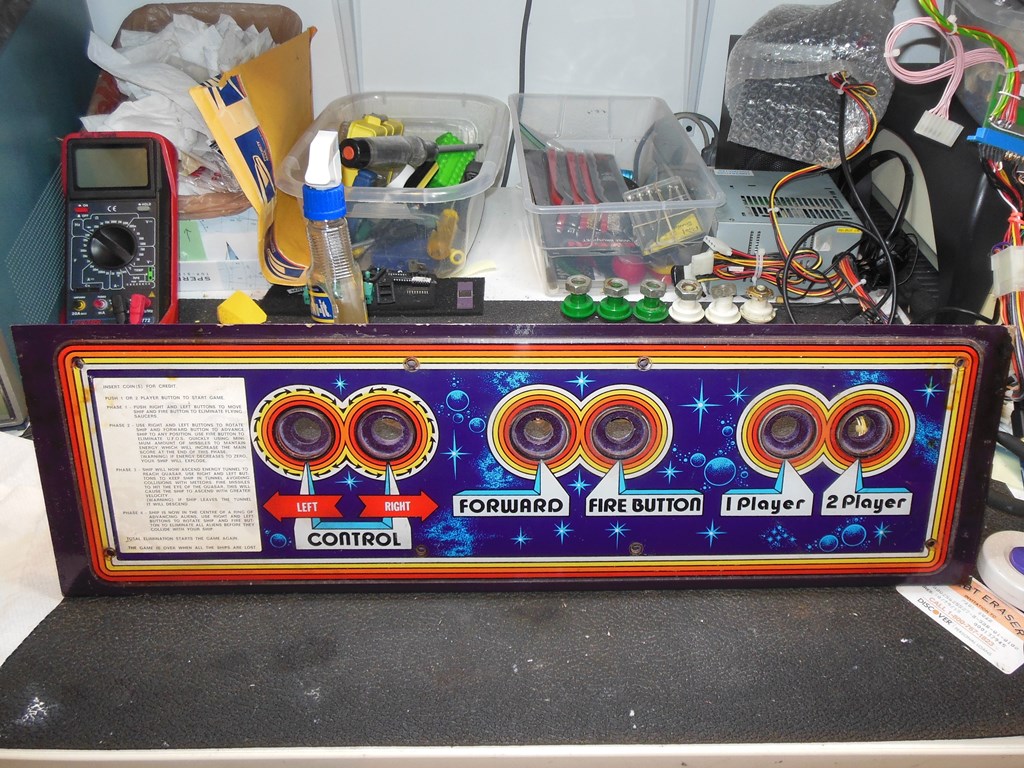
Other than the sticky tape residue, the control panel and glass was dirty and paint spattered but undamaged. There was a small amount of cigarette burn but I'd seen far worse. The monitor surround also looked in good condition - it had been removed before so it had some deformation and tears around the staples. Behind the control panel was the mounting plate that held the ballast & starter for the small fluorescent black light that accents the portions of the artwork on the monitor surround.
|
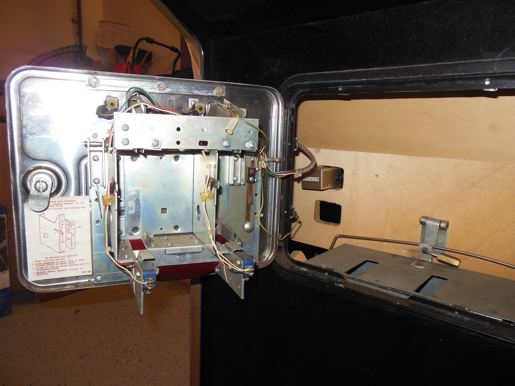
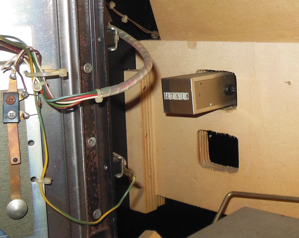
The coin door was missing the coin mechanisms (one of which I found in the bottom of the cabinet) but all the wiring was intact and unhacked. The coin counter read 27,518.
|
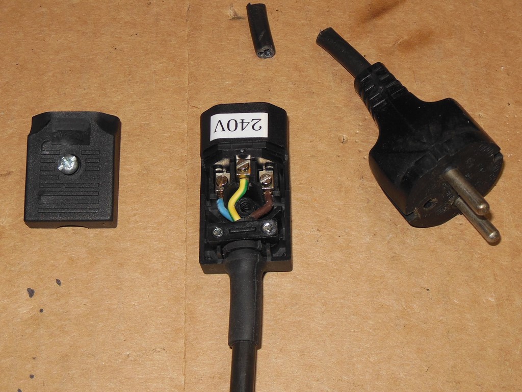
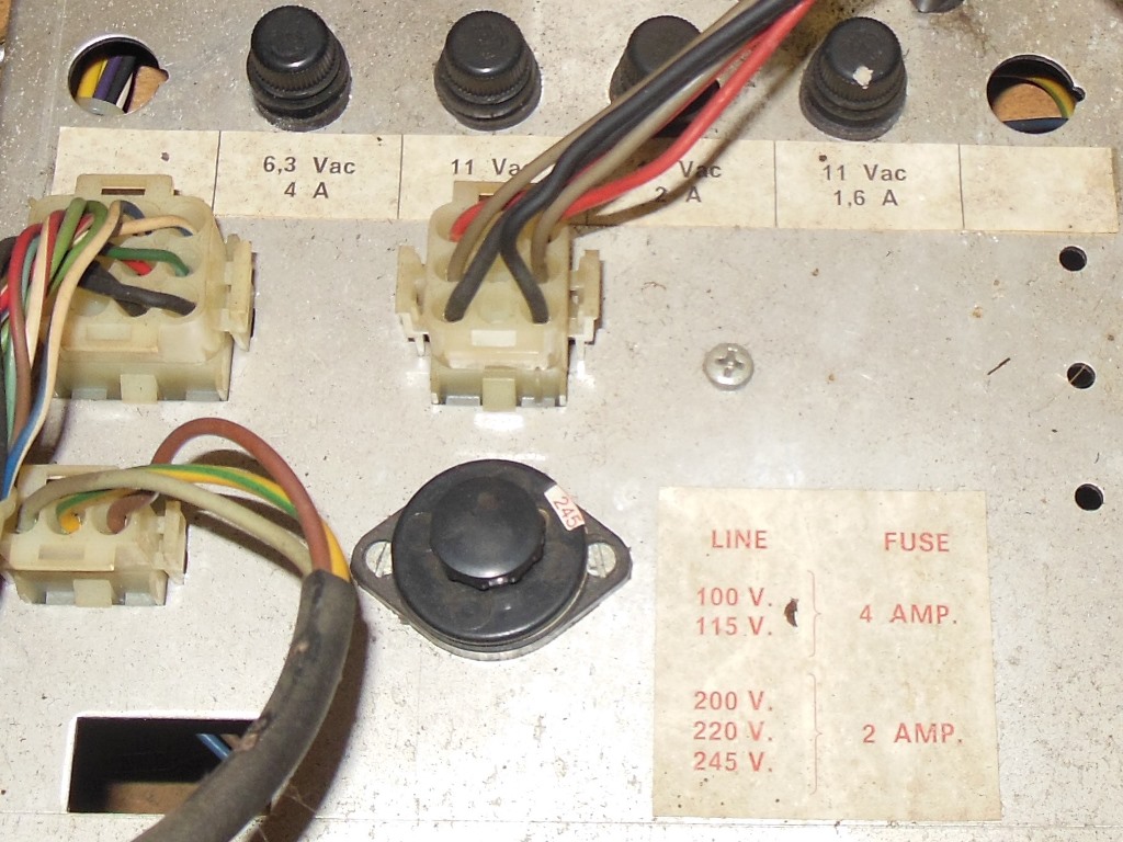
I replaced the old European 220V round pin plug with the standard IEC C14 plug I'd been using for keeping the 240V based games separate from the usual 120V mains. Inside the cab, the empty torn manual packet, fallen of label and 1 Mark coin mechanism were cleaned out and the power transformer voltage selector plug changed from 220V to 245V.
|
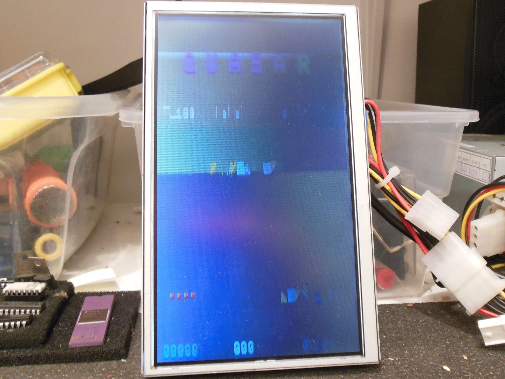
First power yielded no sparks or smoke. The monitor came up but the game itself was crashing with corrupted graphics on screen. The marque light flickered on and off, the small monitor cavity black light was dead and both coin slot lights were burnt out. The cabinet fan seemed to be running OK, however. Voltage readings at the power regulator were -4.82V(-5V), +4.99V(+5V), +11.39V(+12V) and +15.80V(+14V unregulated). At the game board +5.01V was present, all looking good power-wise so I suspected a board fault.
|
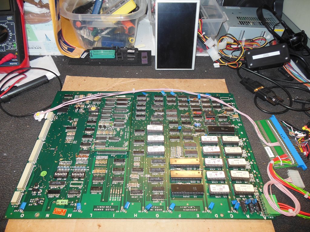
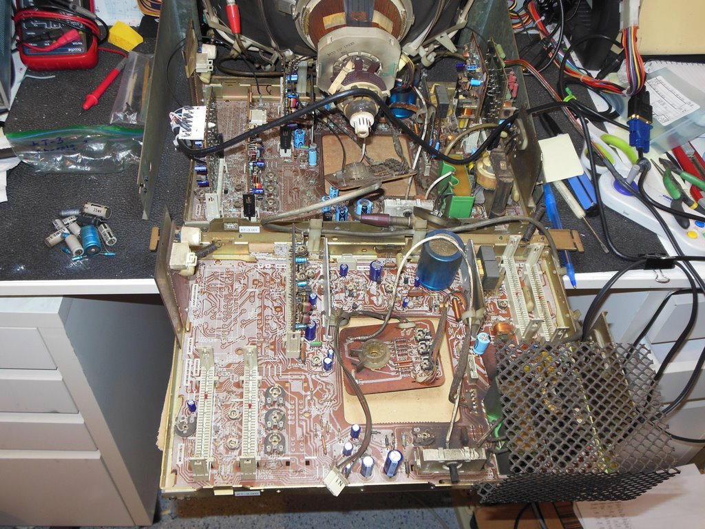
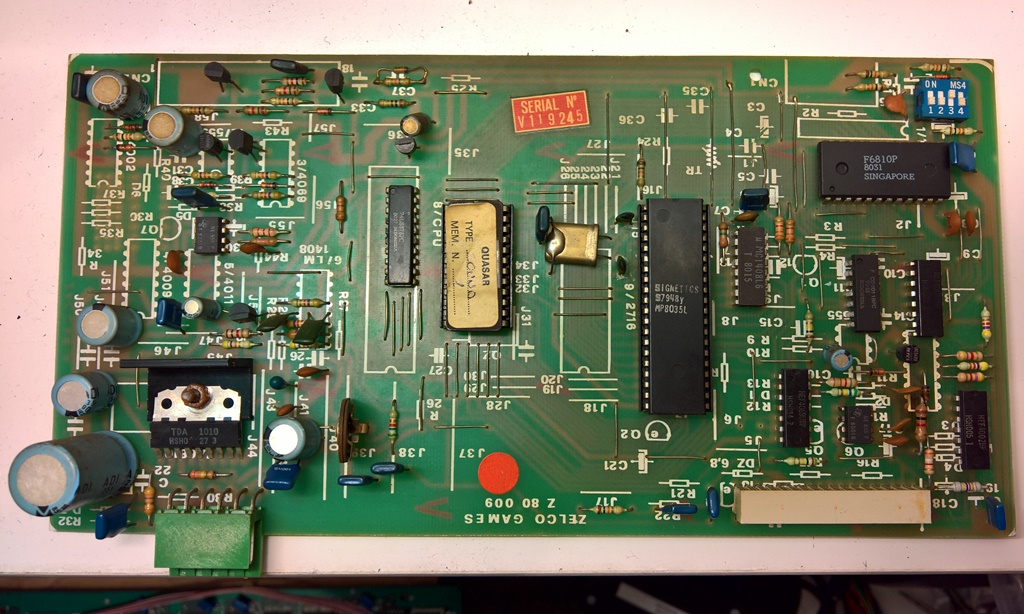
The behavior of the game main PCB was the same on the bench as it was in the cabinet.
Connecting the Arduino ICT flagged a ROM CRC check failure on IC 7B with CRC 0x9DED7808.
The ROM CRC was consistent so this would need further investigation later. The RAM check
flagged multiple issues:
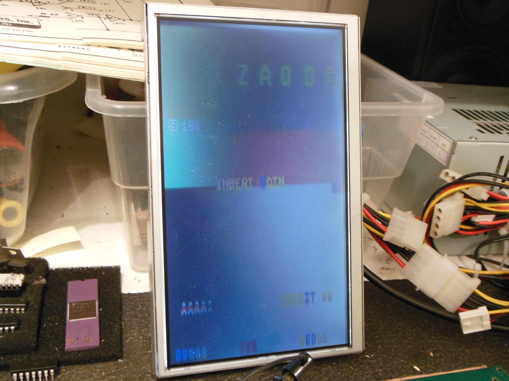
The game now booted and ran OK except that there were bad character colours and the Arduino ICT still flagged "13H 1800 00 04" on "RAM Check All" indicating a bad colour RAM. There was nothing on the scope to suggest this wasn't just a common bad RAM and replacing IC 13H (2102) fixed both the Arduino ICT RAM test and the bad character colours. A few hours of bench testing didn't yield any further faults.
|
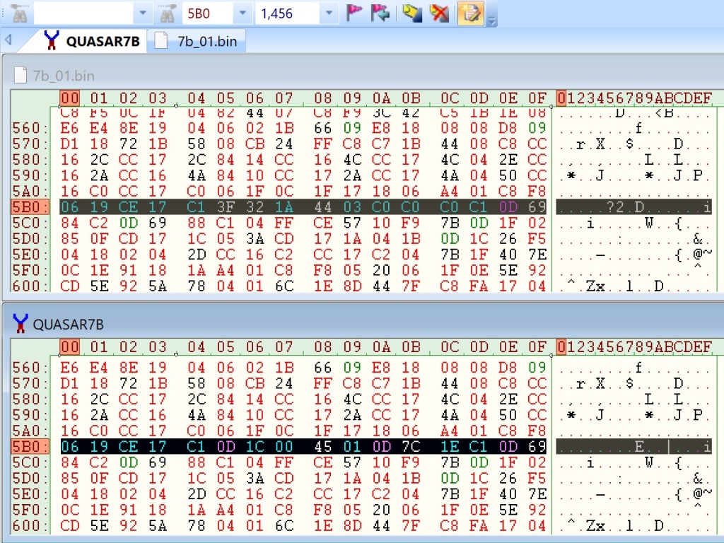
Testing with the Arduino ICT flagged a ROM CRC mismatch on ROM IC 7B. The game seemed to be working OK so I dumped the the ROM to investigate further. Comparing with a known set a difference occurs at offset 0x5B5. The prior known set has code patched out with NOPs leading me to believe that this ROM set is an earlier version of the game and that the ROM image is good.
The dump of ROM 7B merged with matching set of MAME ROMs:
Zaccaria Quasar Set 3

|
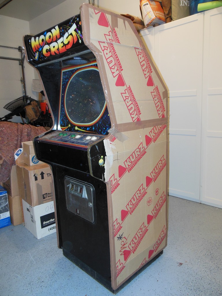
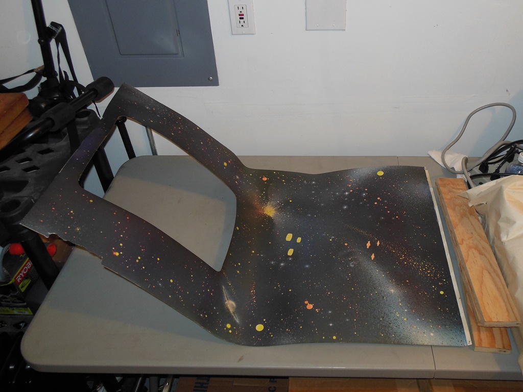
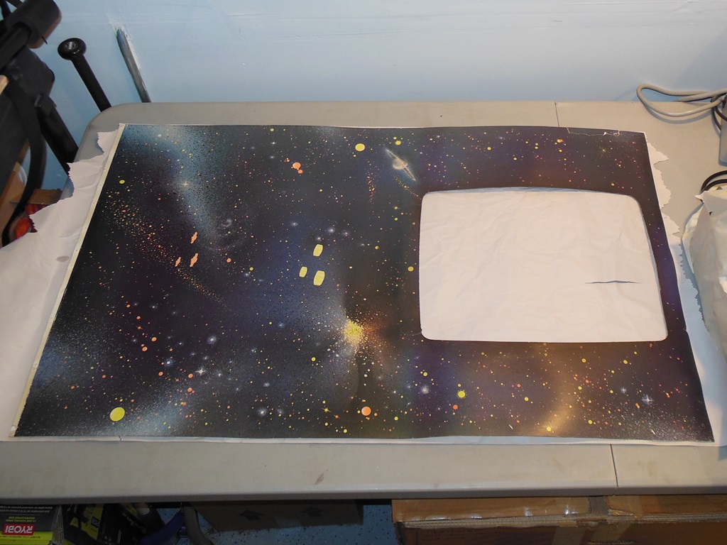
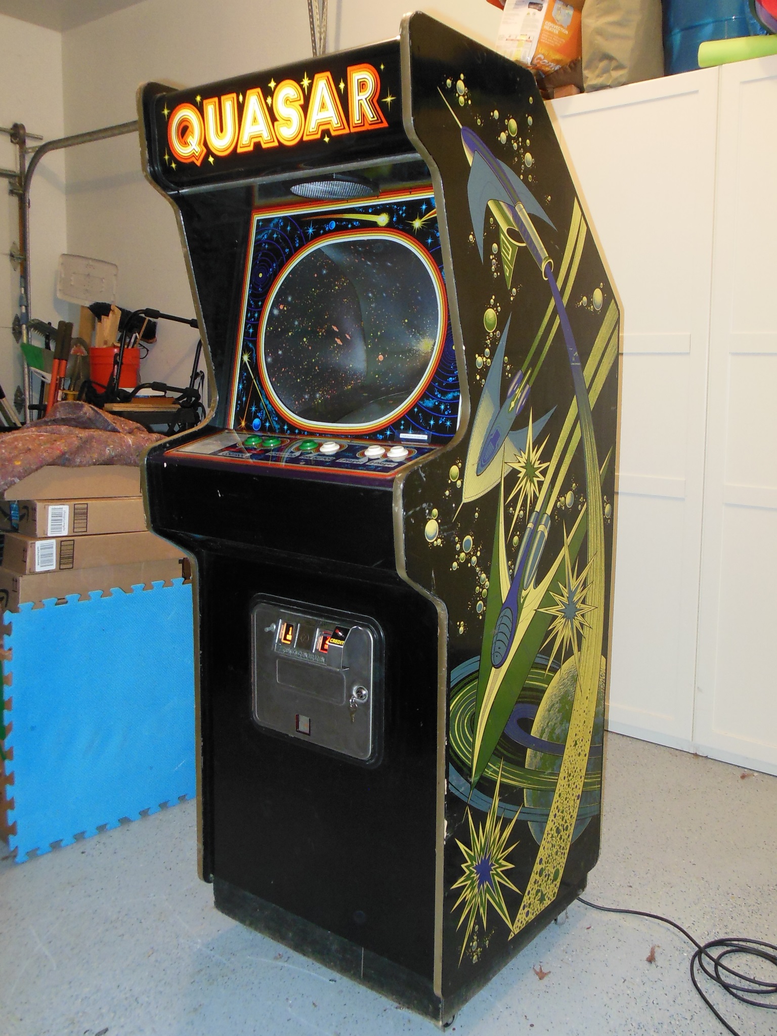
This side art was one of my favorites and I hadn't seen it since the original auction pictures were taken. I took as much care as I could peeling off the packing tape to get off as much of the residue as possible. The tape came off the front of the cabinet pretty well, less so on the top of the cabinet and the back T-molding was a sticky mess of tape glue and fragments :(


|
Underneath the artwork was in good shape for its age and use. Some scratches and dings but nothing overly distressing.
|
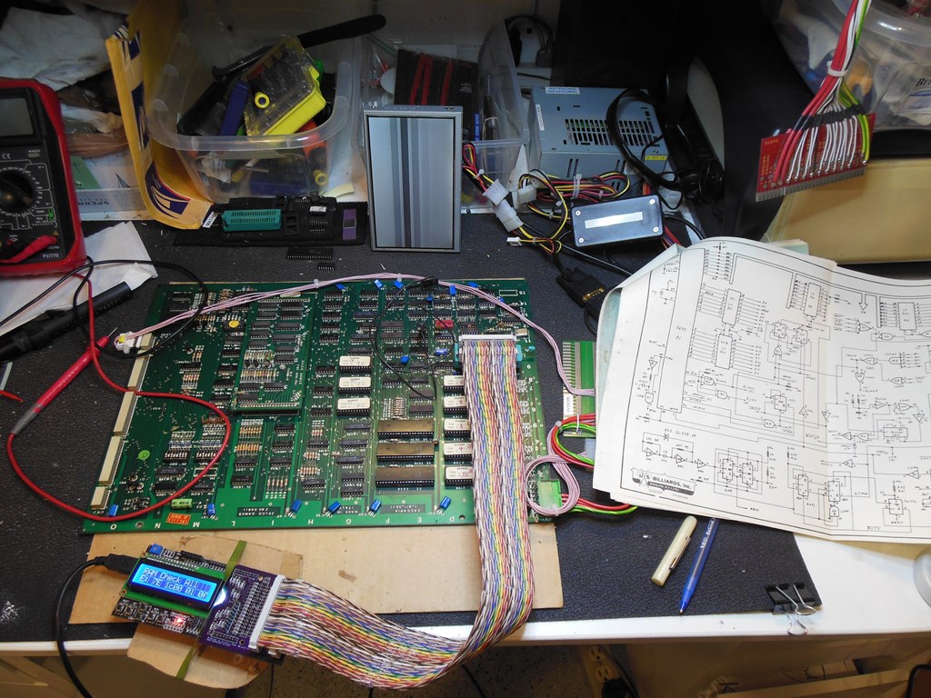
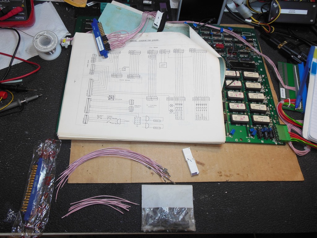
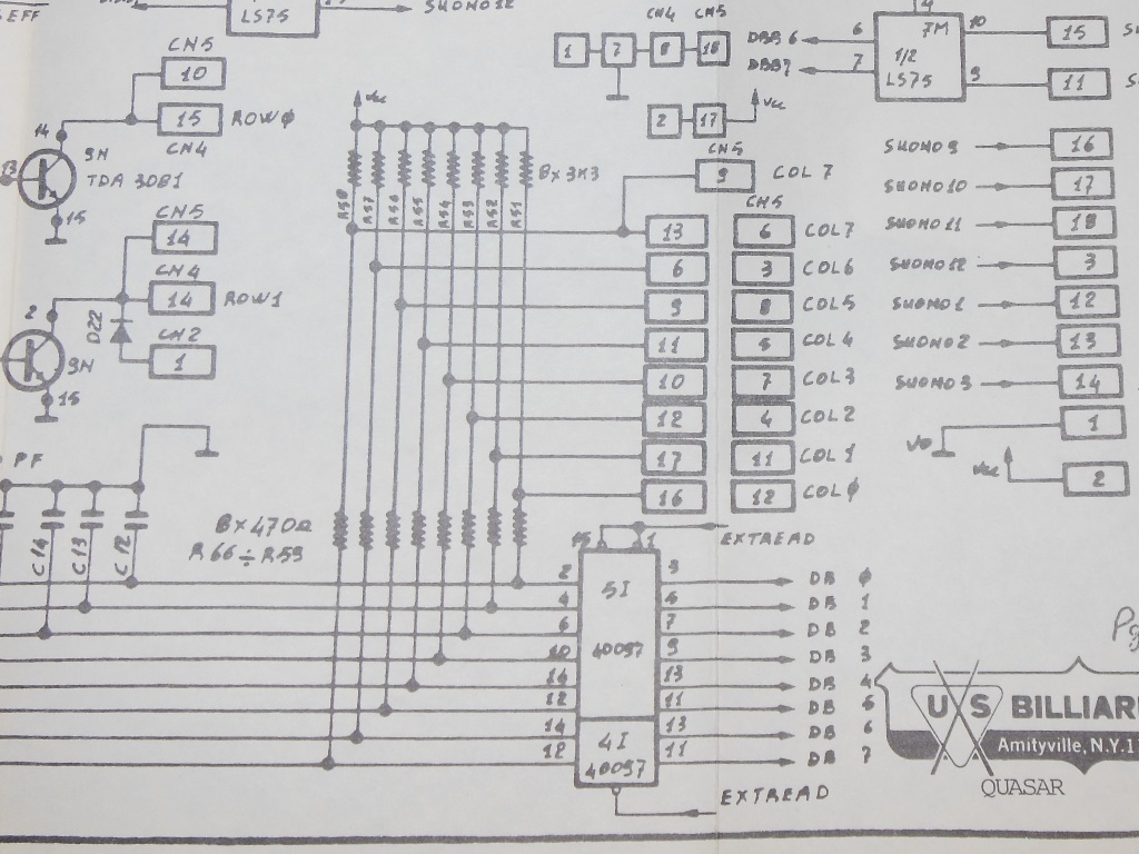
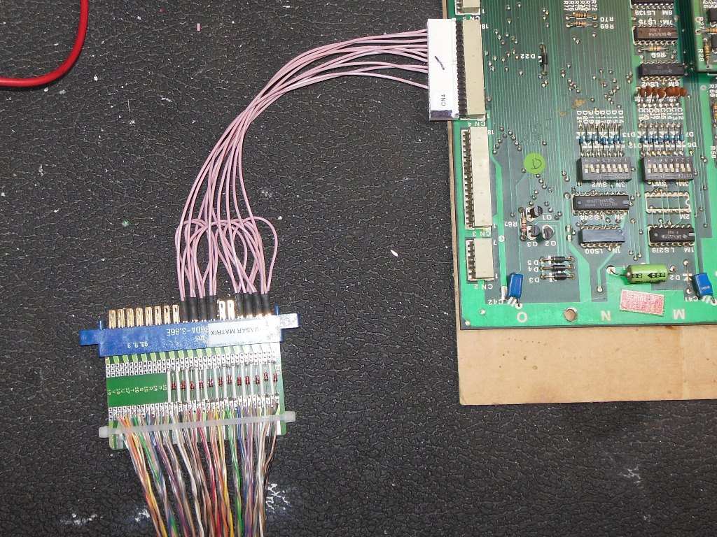
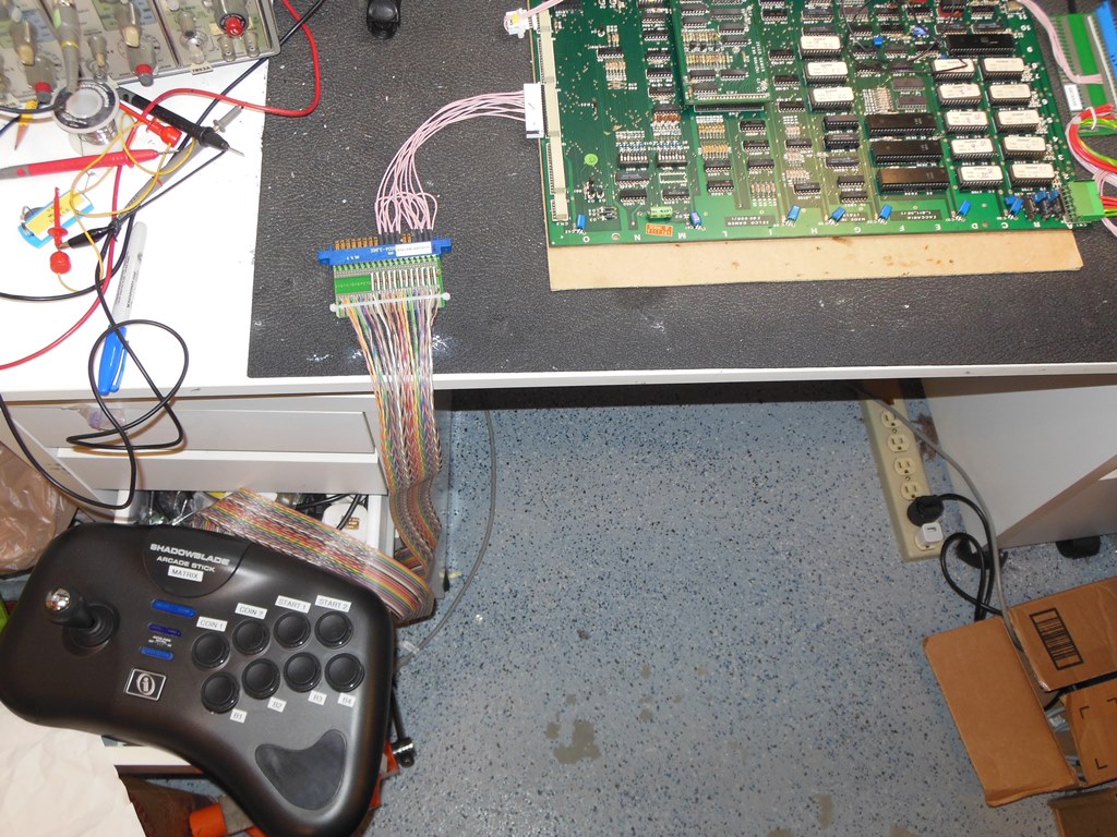
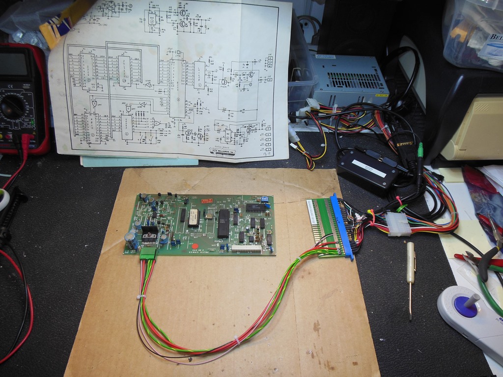
Having previously built a generic matrix control panel for Astro Wars I decided to build one for Quasar to allow it to be play tested on the bench. Though the wiring diagram in the manual shows CN5 used for coin/test/service and CN4 used for game control inputs, the schematic showed all the signals on CN5 were also available on CN4 such that only a single connector was required to connect all the inputs.
|
The matrix adaptor worked fine and no issues were found with the game board - all the inputs were working OK.

|
Retesting the repaired Quasar main PCB back in the cabinet still encountered boot problems :|

|
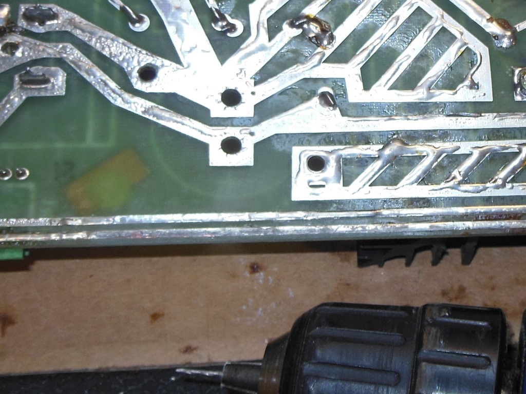
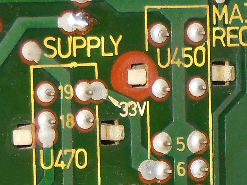
I'd already spotted a broken off capacitor on the regulator board on the -5V rail. Since the main PCB used triple-voltage 2708 EPROMS I surmised it or other cap problems could be the cause of the intermittent boot problem in the cabinet. As has been the case in the past, once a capacitor fails I apply a full cap kit on the regulator board that includes fitting the +5V adjustment pot option. Also on this particular boards the +5V capacitor was screwed in place and thus a couple of holes needed to be drilled through the PCB to be able to use a standard through-pin soldered capacitor.

|
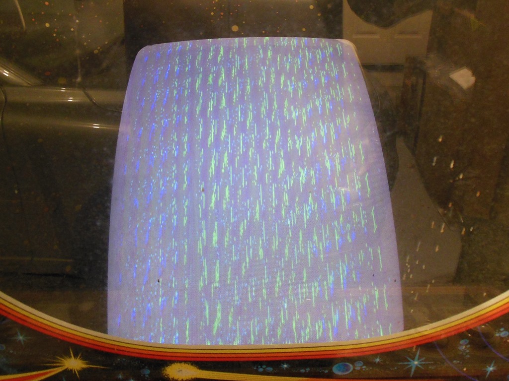
On retest the game appeared to stay booted now but there was no sync and the monitor exhibited an intermittent shutdown/restart problem. Opening up the chassis found at least one capacitor dangling by a sole remaining pin so the monitor chassis at least needed a cap kit.
|
The two wing nuts securing the marque light rear access panel were both only hand tight and unscrewed easily. The marque light and Moon Crest marque nuts were all easy to remove so I suspect it hadn't been long since the original Quasar marque had been replaced with the Moon Crest one.


|
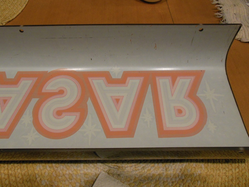
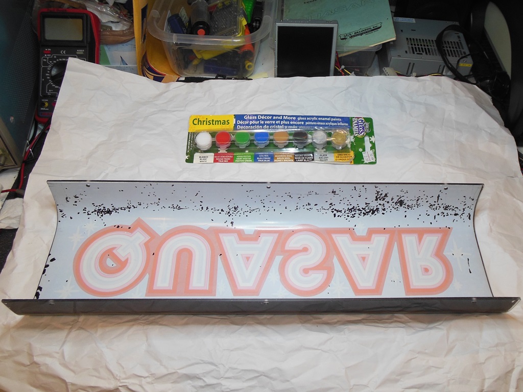
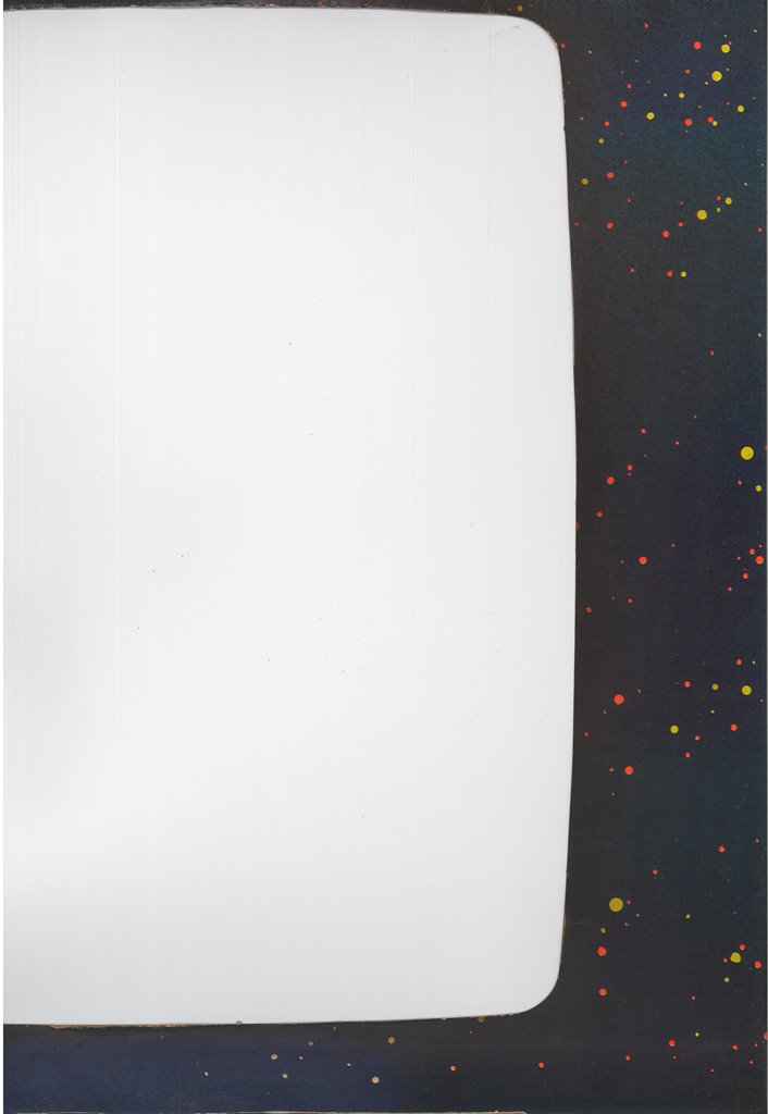
Scanned in the Quasar marque - the curved over portion is blank so there was no
need to scan it.
600 DPI Quasar marque scan (27.0MB).
|
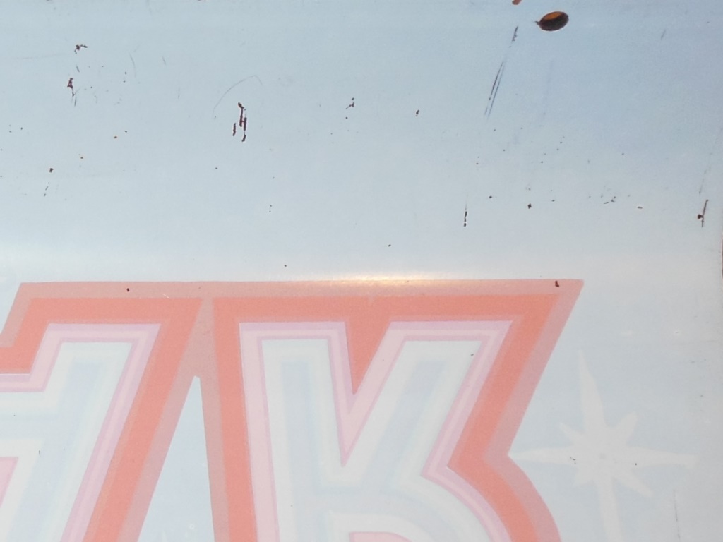
The spare Quasar marque I had to fit into this cab had some damage to the artwork. Most of the damage was to the black areas of the marque that are opaque to light, making the damage barely visible with the marque light off but clearly visible with it on. The original paint must have had at least two coats - a coat of black on the front and white on the back. For the touch up I used black paint to match the visible side of the marque, leaving the back of the marque looking messy. I could have painted over it with white paint but decided to leave as is since it's not visible when fitted in the cab.

|
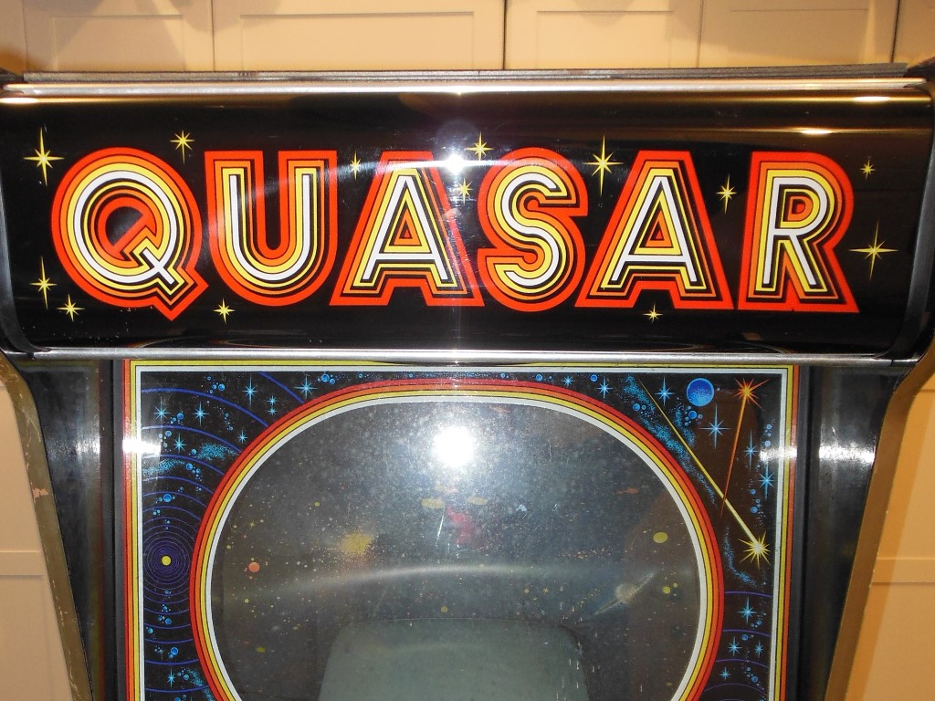
The repaired Quasar marque was fitted into the cab and tested out. As far as I could tell it looked good.
|
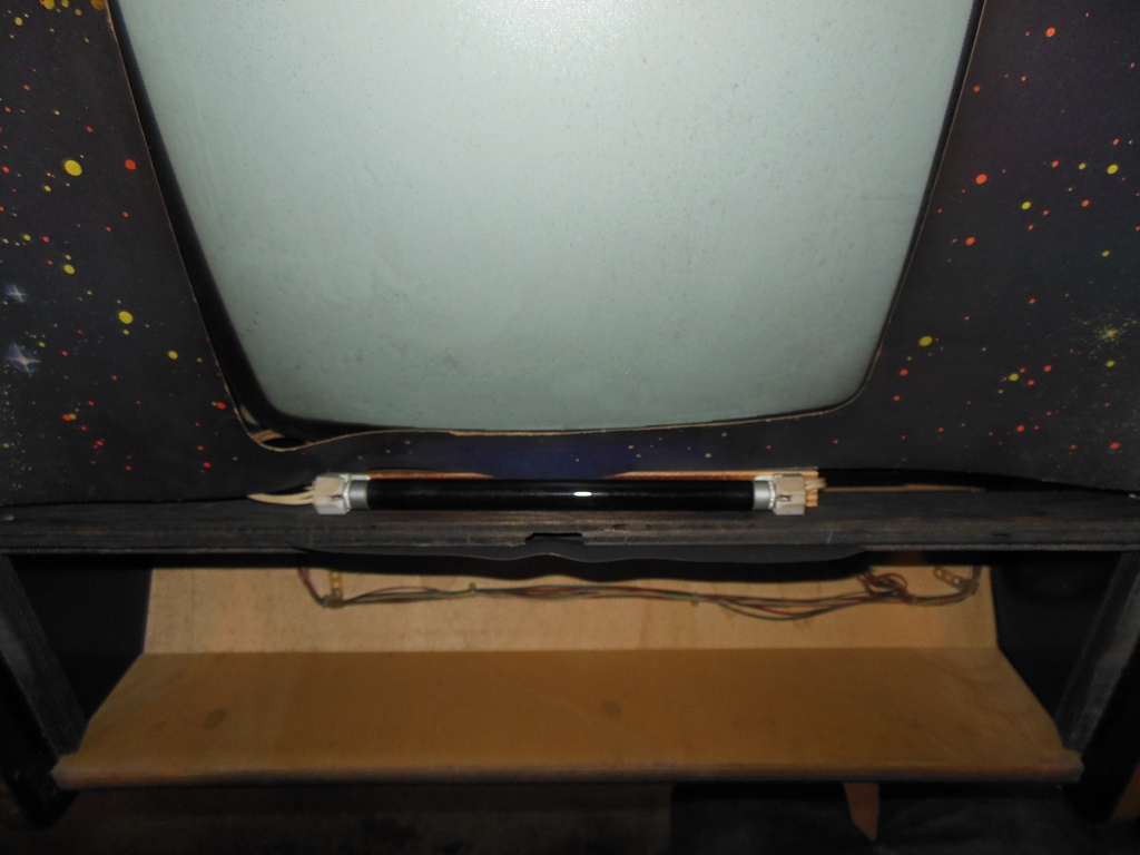
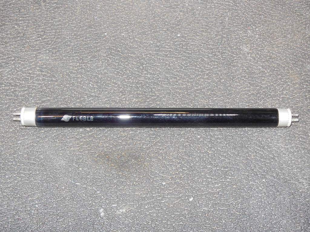
The small fluorescent black light that highlights portions of the monitor surround was completely dead. Removing the FL6BLB black light blue tube and testing it on the bench with a multi-meter found the heater on one side open. I ordered a couple of replacement tubes from eBay.
|
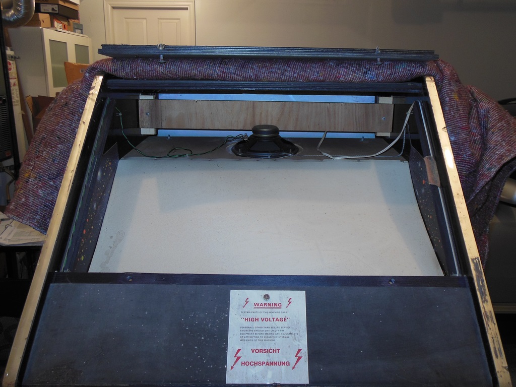
The monitor surround was removed by levering out the row of rusted staples along the top edge near the marque and a couple of staples on each side of the monitor. The surround had some minor creasing above the monitor area, some discoloration along the bottom due to the blacklight and a portion torn off on the right side. Thankfully the torn piece was still attached by half a staple to the frame.
|
|
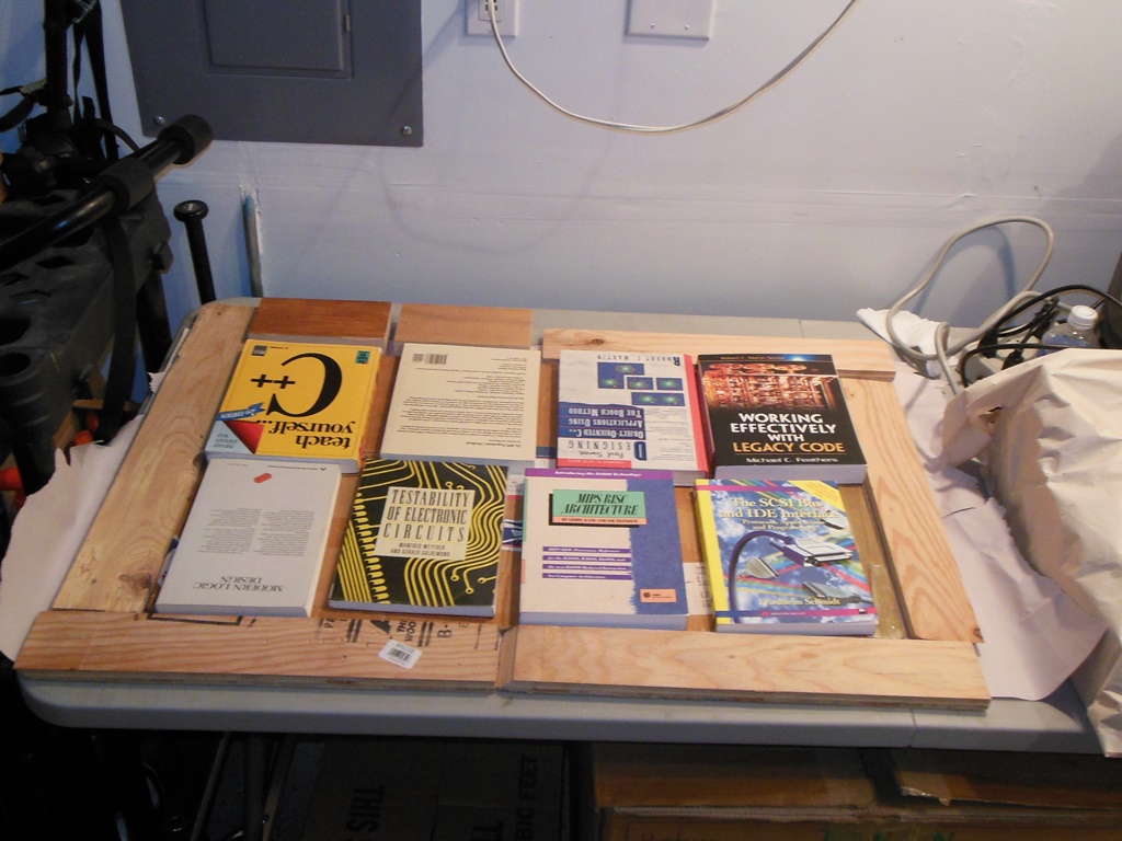
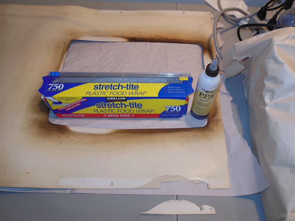
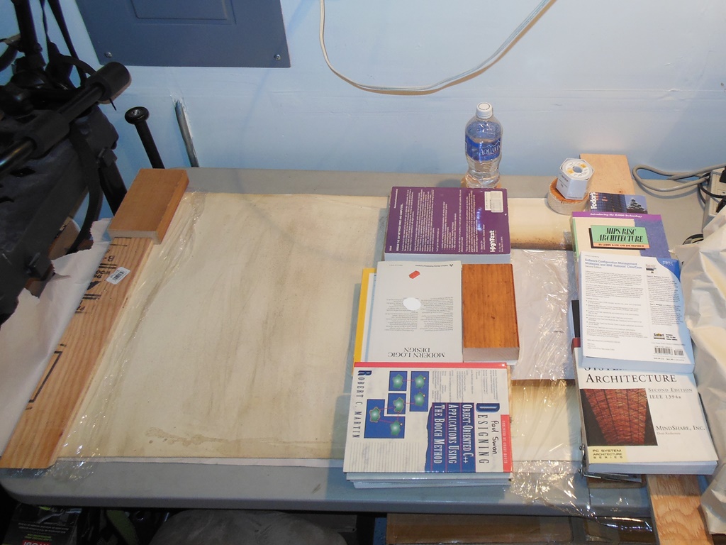
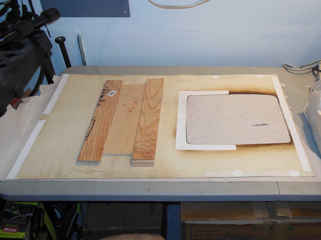
In order to scan and repair the surround the first step was to wipe down both sides with a damp cloth then leave it for a few days under a foam tile and book weights for a few days to flatten out.
|
|
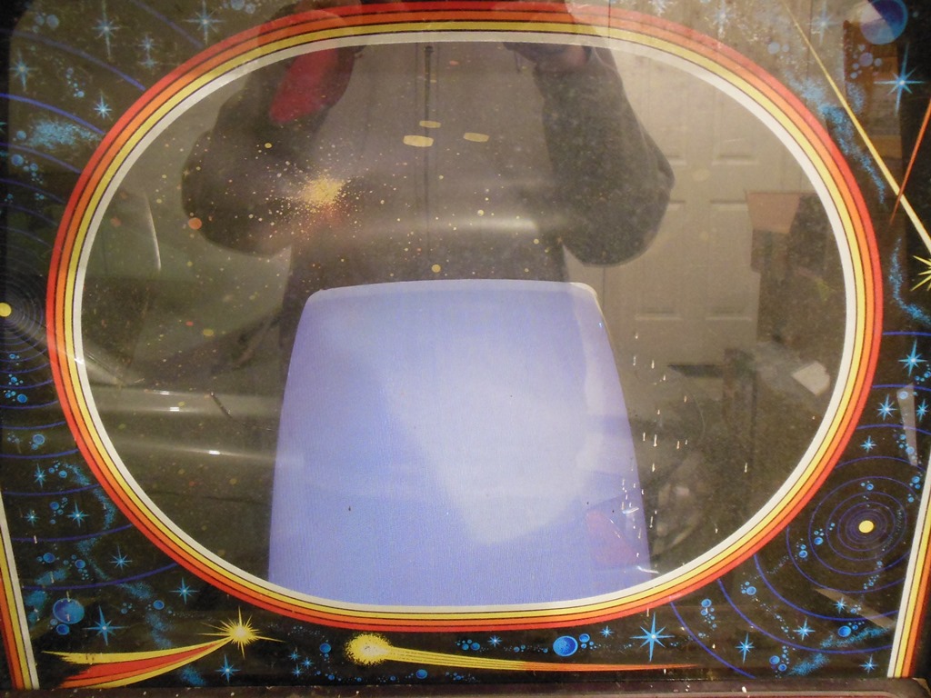
Scanned in the Quasar monitor glass.
300 DPI Quasar monitor glass scan (8.0MB).
|
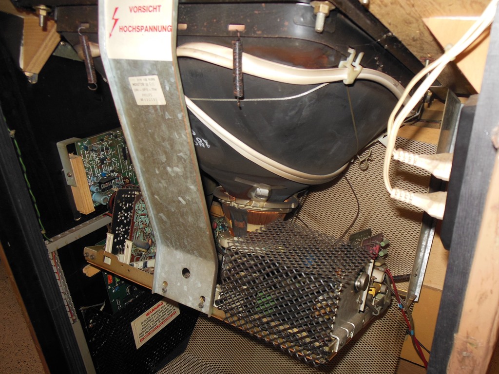
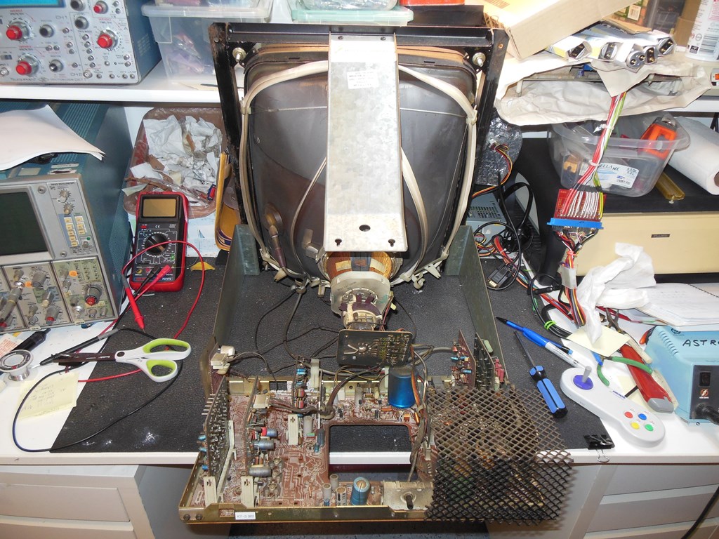
Since the monitor surround was out and the monitor needed repairs I decided to remove the entire monitor. The monitor is attached to the cabinet by six screws, in this case four large bolt screws and two wood screws. With these screws removed the whole monitor can be slid out of the back of the cabinet.
|
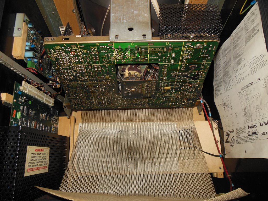
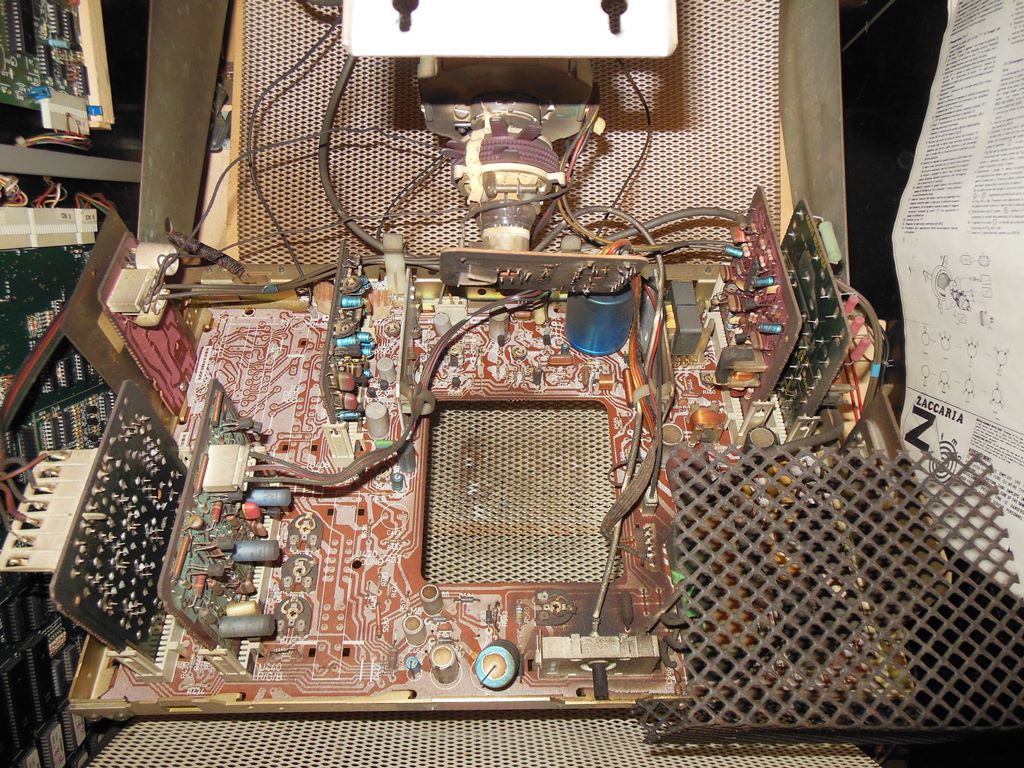
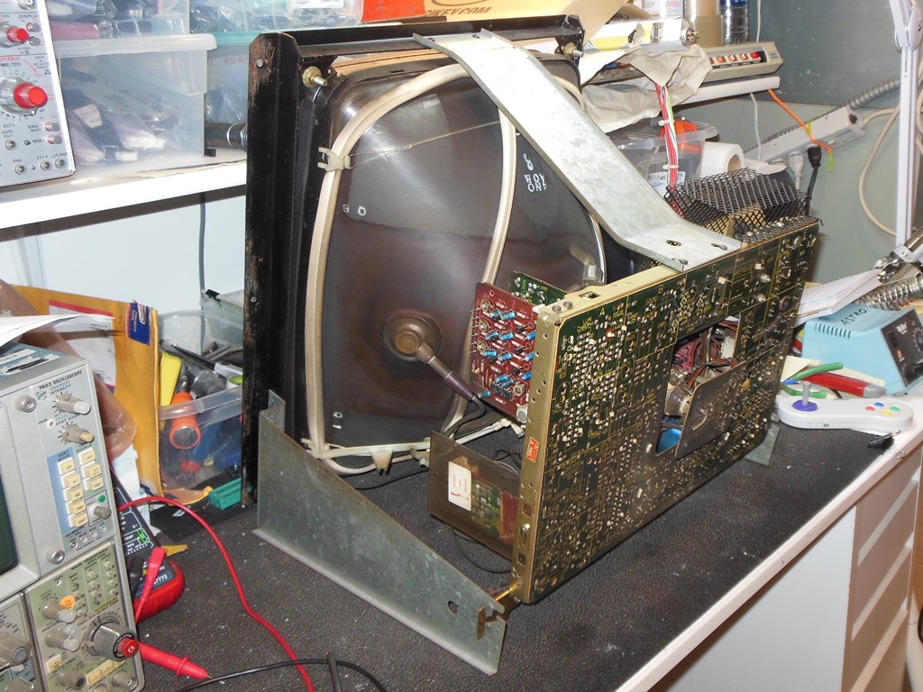
The Philips KT-3 monitor chassis is quite large with about a third of it unpopulated TV components (e.g. audio amplifier & tuner).
|
Removal of the two top screws allowed the chassis to fold open to allow easier fault diagnosis.
|
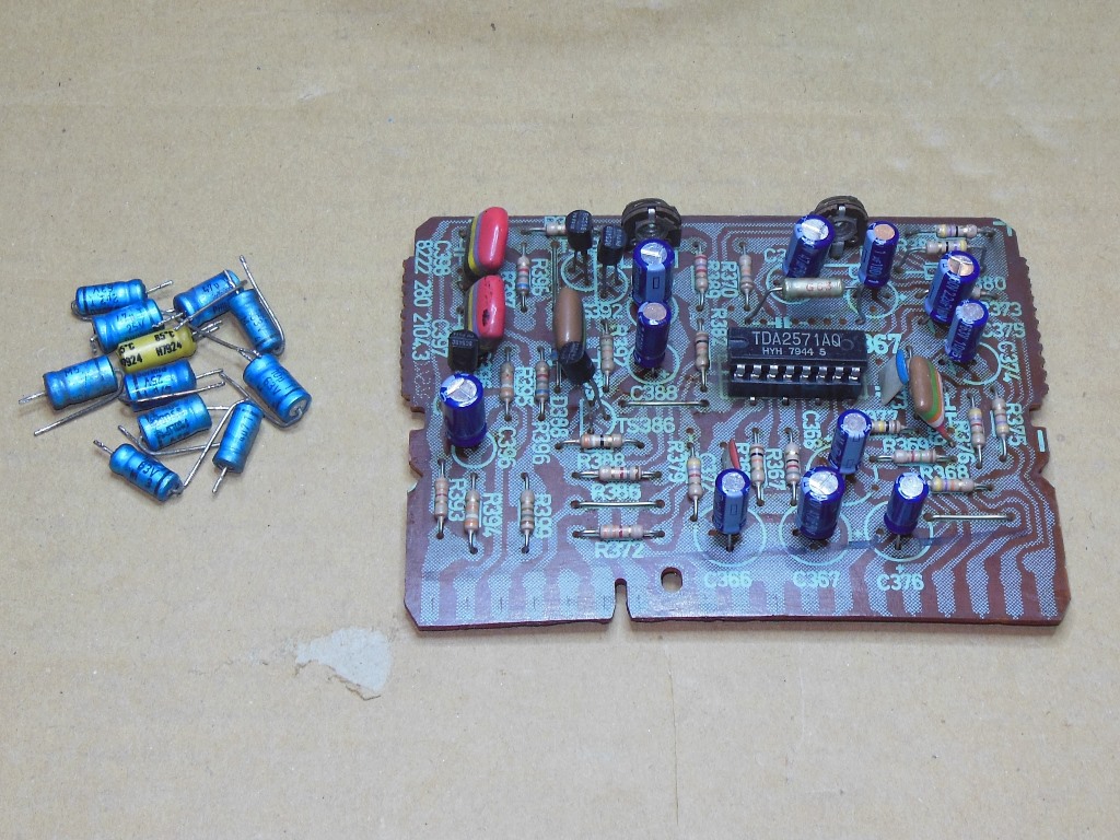
The monitor behaved the same on the bench as in the cabinet. Swapping in a known good "line frame sync" daughter PCB confirmed my suspicion that the one in the chassis had failed. There is only one IC on this daughter board, a TDA2571, so I decided to remove, socket and replace the TDA2571 with a new one to start with.
|
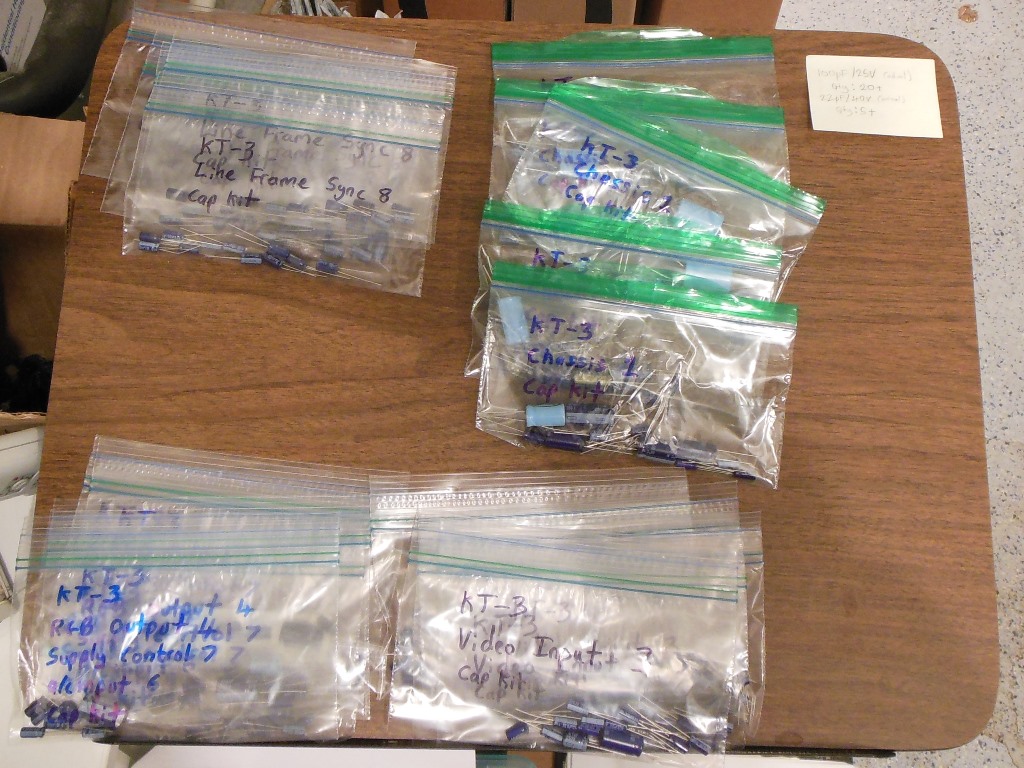
I'd already installed an ad-hoc cap kit in the US Billiards Quasar KT-3 chassis but I had several more Philips KT-3 based cabinets still to restore so I decided to make up a few DIY cap kits for this chassis.
|
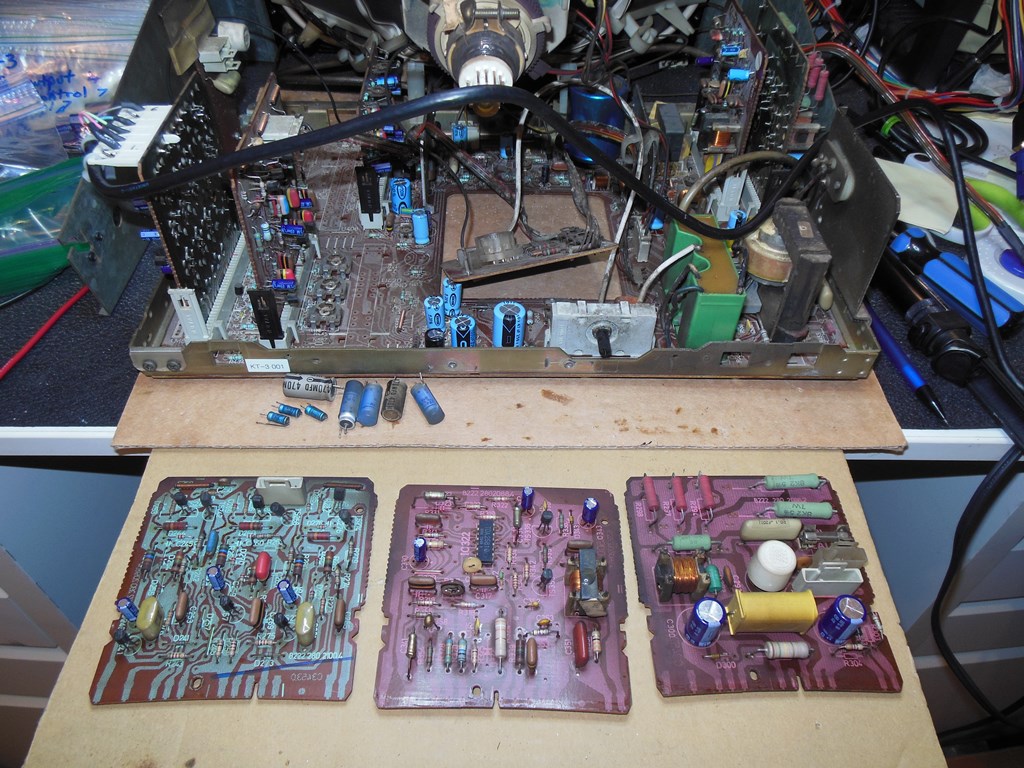
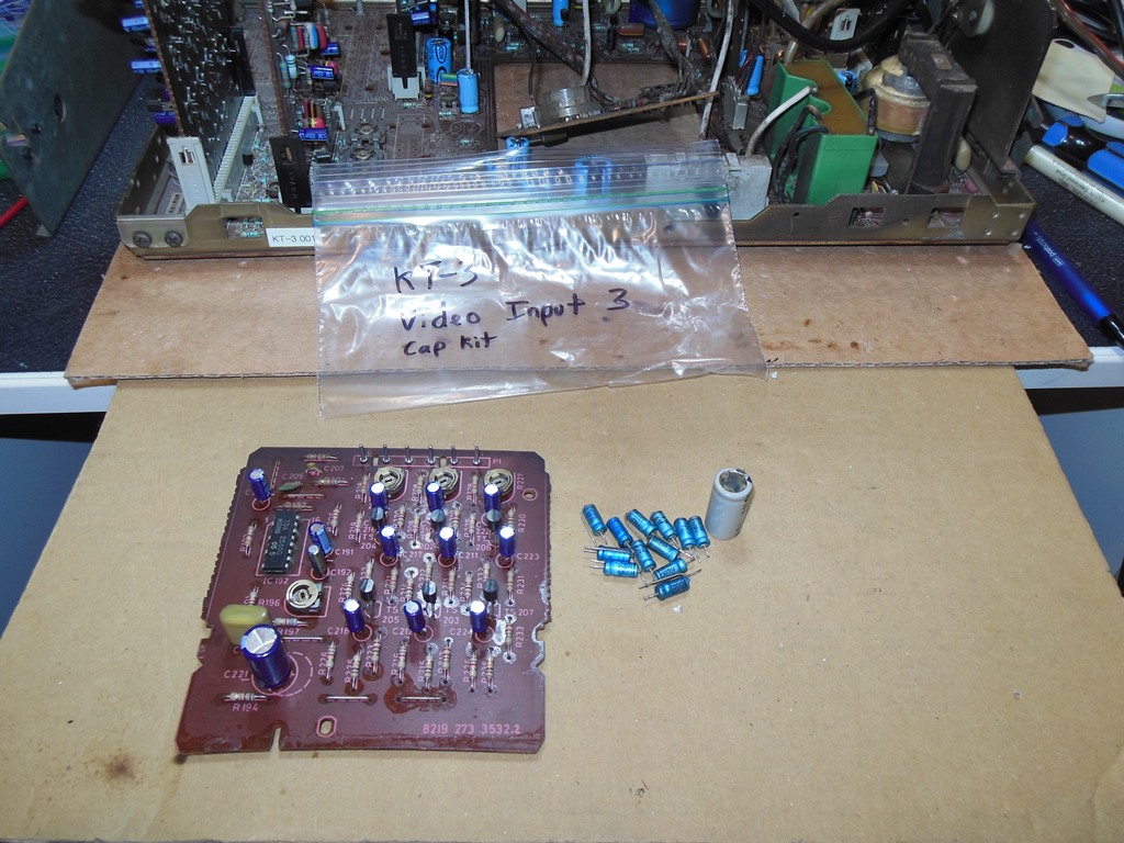
The DIY cap kits were fitted to all five daughter boards and the main chassis.
|
Retesting the monitor on the bench yielded a good stable picture, confirming the TDA1571 on the line frame sync PCB had failed, however there was still an intermittent shutdown problem to diagnose. Tapping some of the daughter boards caused various effects and pushing on the supply control daughter board caused the monitor to shut down.


|
Flipping the chassis back up to inspect the daughter board connector joints revealed numerous dry joints on several connectors. Reflowing all the pins on all the connectors and the line transformer fixed all of the intermittent issues. The monitor ran fine for several hours on the bench.
|
I took the opportunity to clean the monitor shelf and surrounding areas whilst the chassis was out prior to fitting the monitor chassis. Reinstallation was accomplished by sliding the whole monitor back into the cab and securing with the four large bolt screws and two wood screws. After reconnecting the power & video on power up the monitor was still working properly.
|
The replacement FL6BLB black light blue fluorescent tubes arrived. Fitting a new tube was all that was needed to fix the black light.

|
The control panel was in reasonable condition aside from the large amount of packing tape residue. The buttons were also all OK though at some stage the player 2 start button had been replaced that I decided to leave as is since it's not noticeable from the top.
|
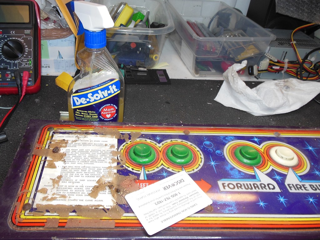
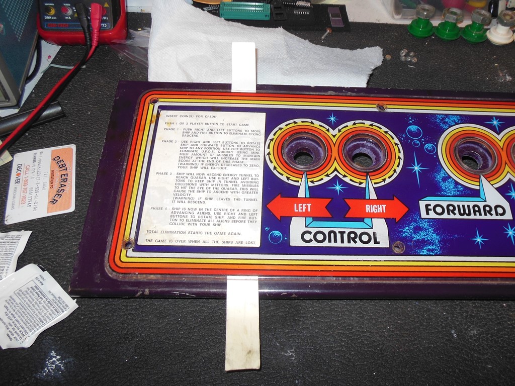
The tape residue needed a lot of Goof Off (a citrus based cleaning agent) and credit card scraping elbow grease to remove.
|
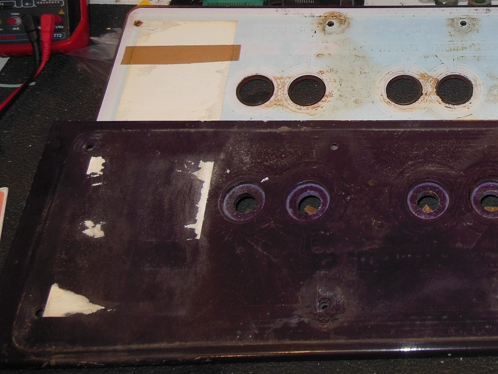
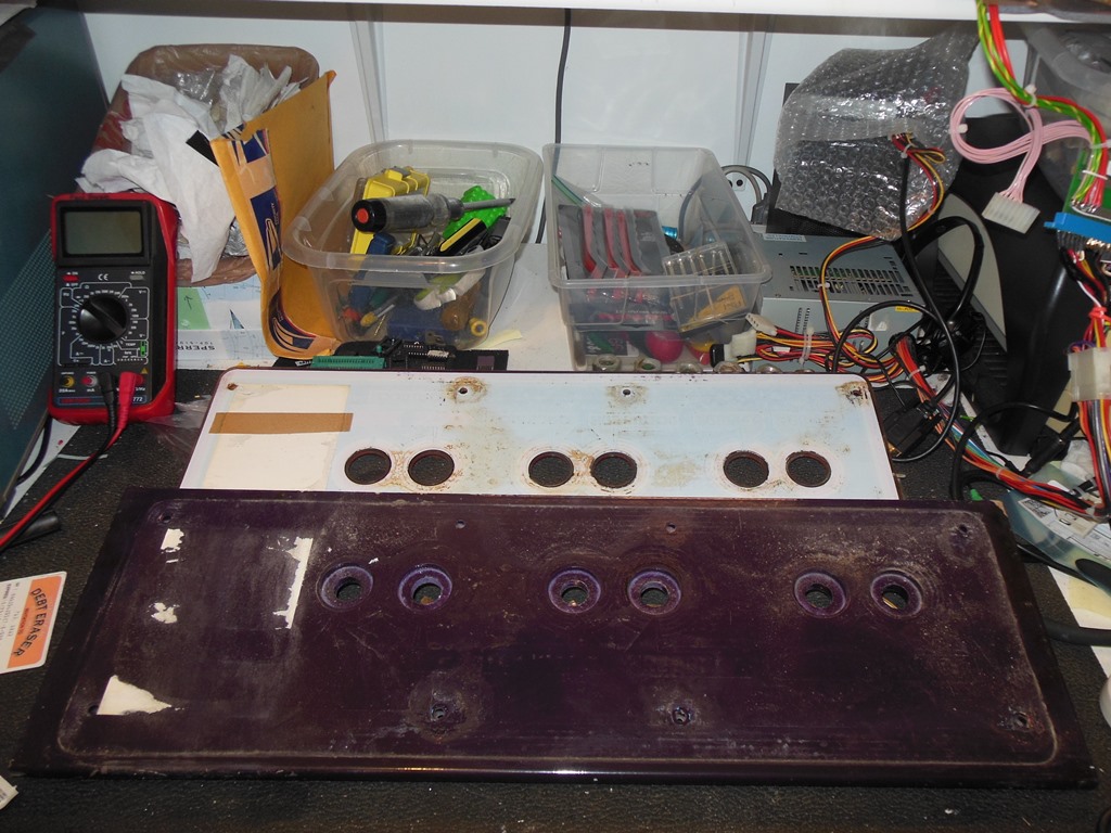
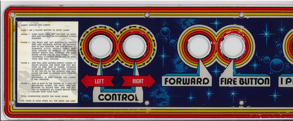
The control panel overlays are normally straight forward to remove by removing all the screws and buttons. In this case, the instruction sheet (a piece of carboard sandwiched between the overlay and the panel) had become stuck to both the overlay and the panel. Using a thin strip of cardboard I gently levered across between the sheet and the panel to separate off the sheet. Most of the sheet separated except for a portion of the left side and left corner. I decided to not attempt to separate the instruction sheet from the overlay and leave as is. Both the bottom of the overlay and top of the panel had a lot of dirt and spilled liquid residue that I removed using a plain damp cloth (no chemicals on the print side).
|
After a few days flattening the monitor surround was flat enough to repair the torn piece and apply reinforcement strips around creases and stressed areas. These were left to set for another few days.
|
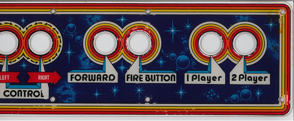
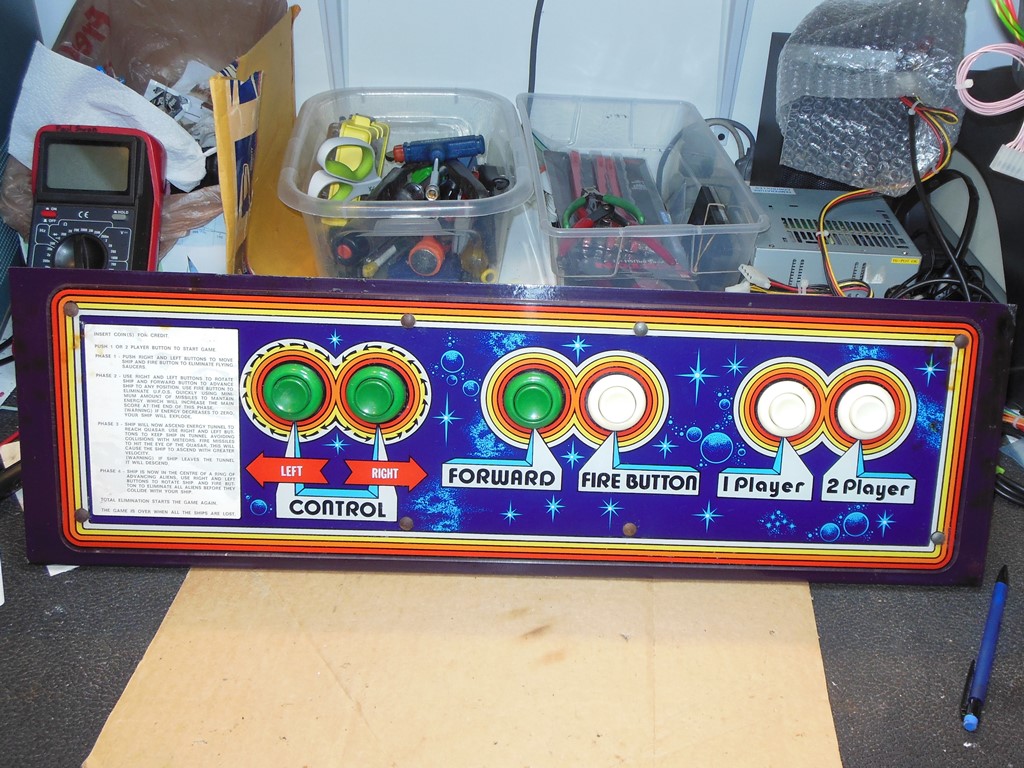
Scanned in the Quasar control panel overlay.
600 DPI Quasar control panel overlay scan (26.8MB).

|
After cleaning the overlay, panel, leaf contacts and all the buttons the control panel was reassembled and installed back into the cabinet for testing. All the controls were working OK.


|
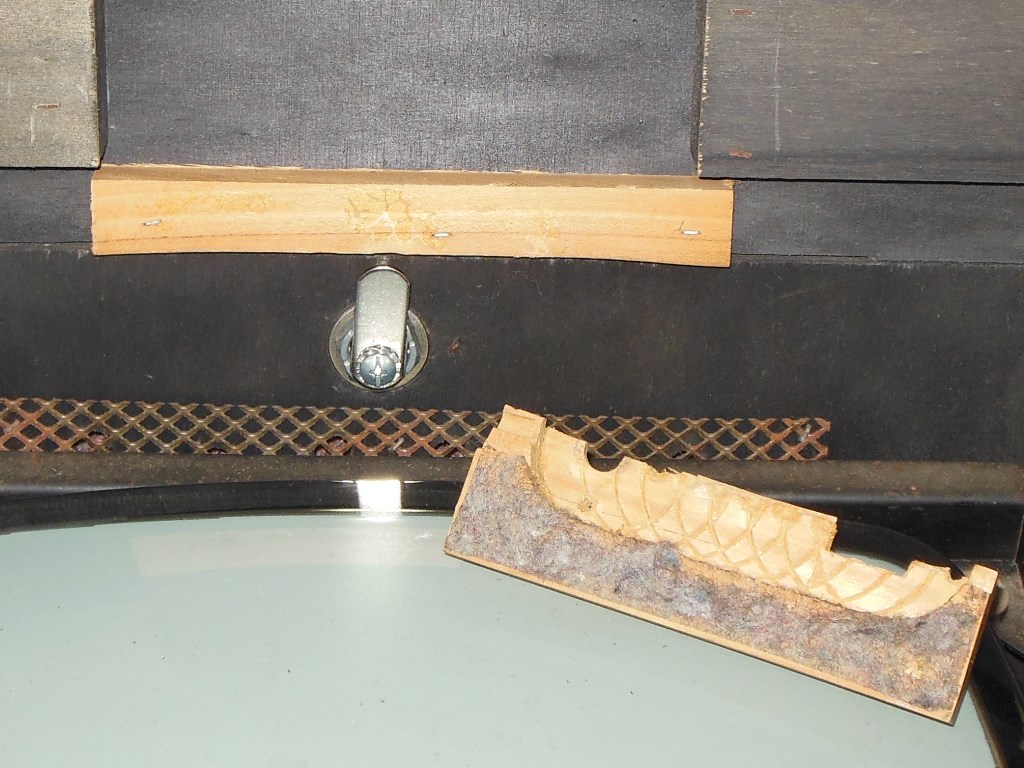
Whilst changing the locks to Happ A05 that I'd been using for all my games I discovered that the back door frame lock lip had been sawn off and subsequently repaired using a piece of old molding glued over the top. The repair wasn't solid and the molding piece easily pulled off. I made a more solid repair along with an angled cam for the back door lock to fit.

|
After a few days the repairs had set and the surround was ready for scanning and fitting back into the cabinet.
|
|
|
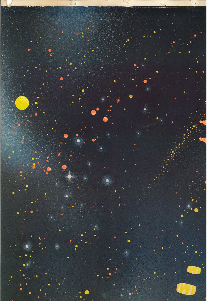
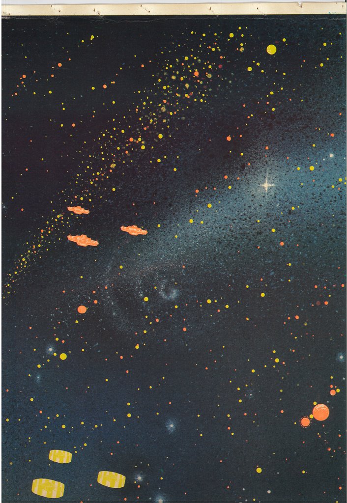
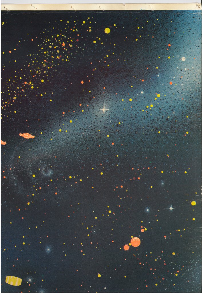
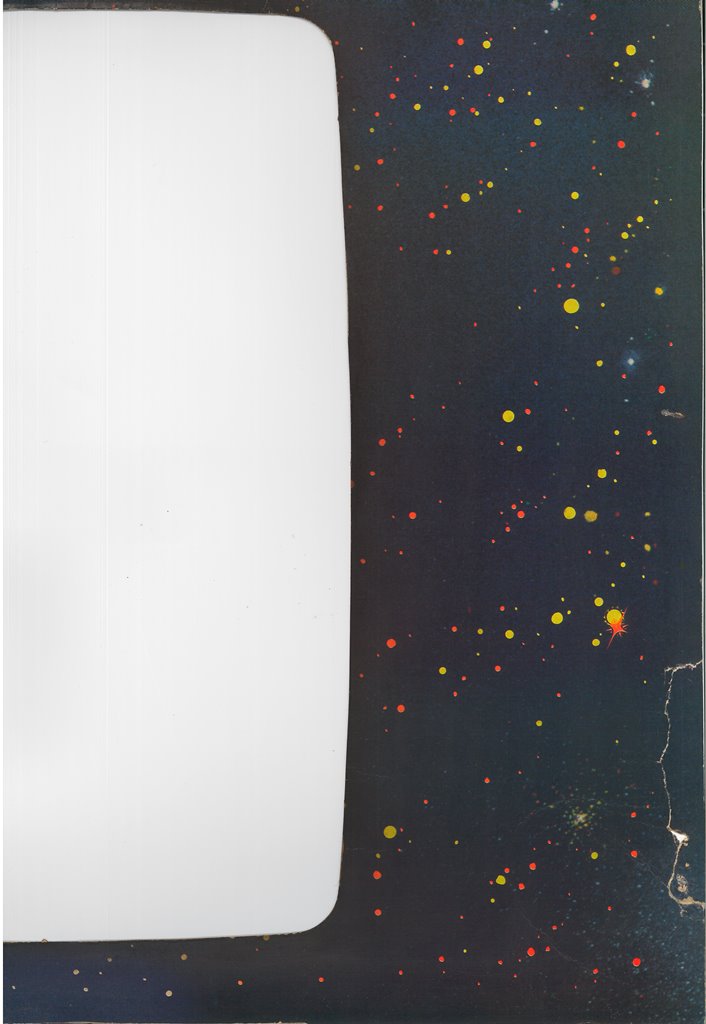
Scanned in the Quasar monitor surround.
300 DPI Quasar monitor surround scan (53.1MB).


|
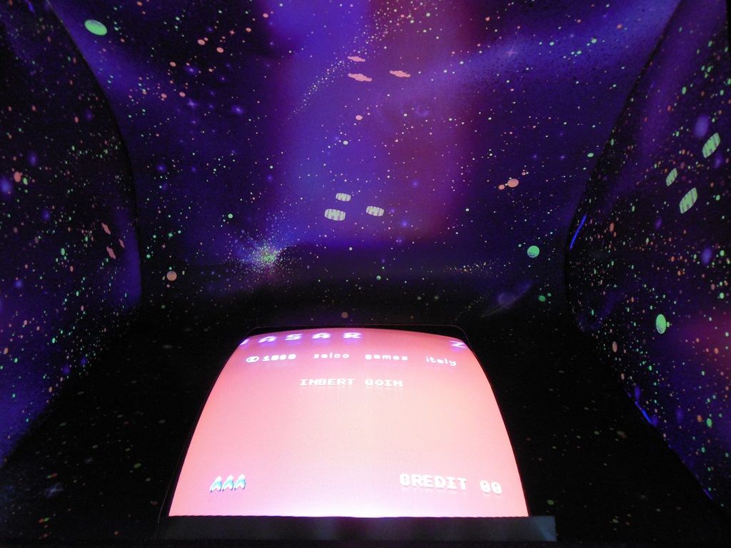
The monitor surround was reinstalled into the cab via a small gap in the monitor glass side runners that allowed the surround to be fed into the monitor cavity. Once it was in the cavity it was adjusted into position and the top row stapled. Four side staples secured each side of the bottom section, the same as the factory.
|
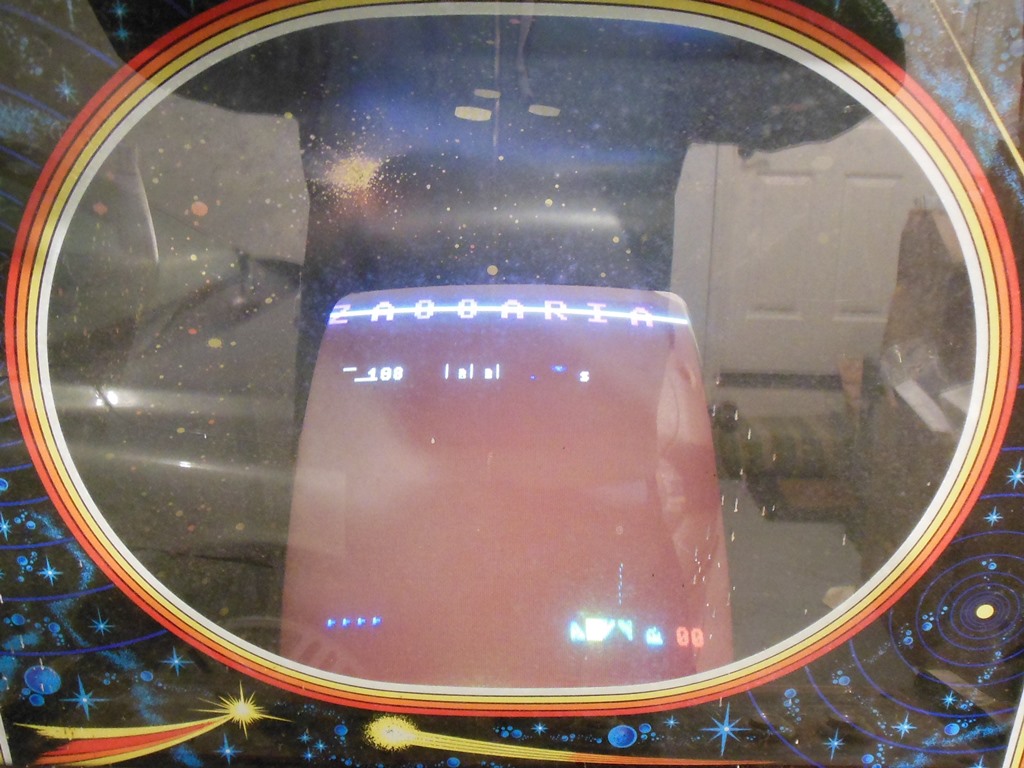
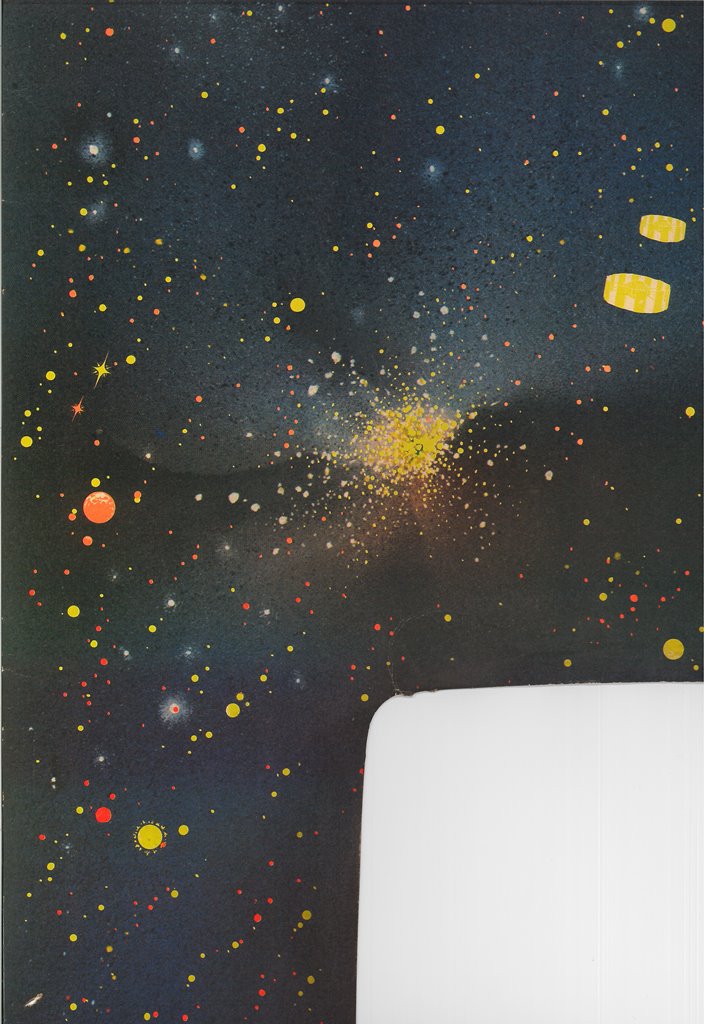
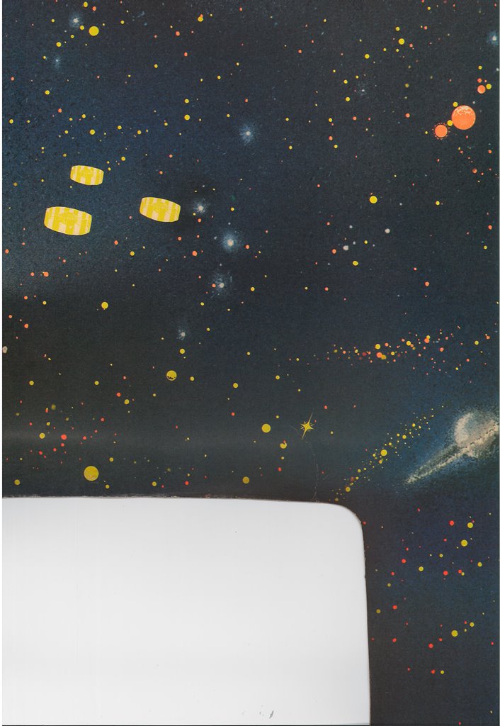
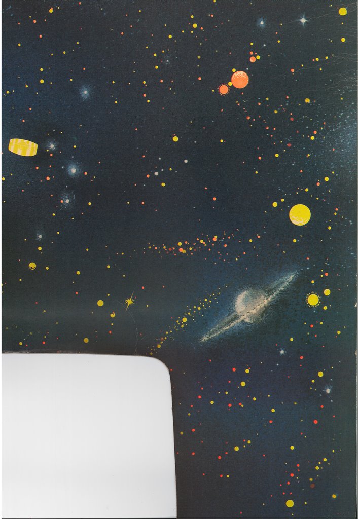
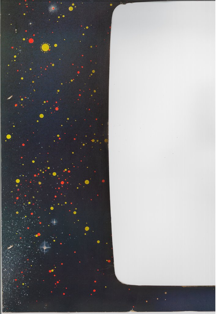
With the game running and the black light on, the net effect gave the background deep colour and glowing highlights on the space ships :)
|
After an hour or so of burn in testing a spot check on the game discovered that the audio had become scratchy. By the next spot check an hour later the audio had gone entirely. The rest of the game appeared to be working OK.
|
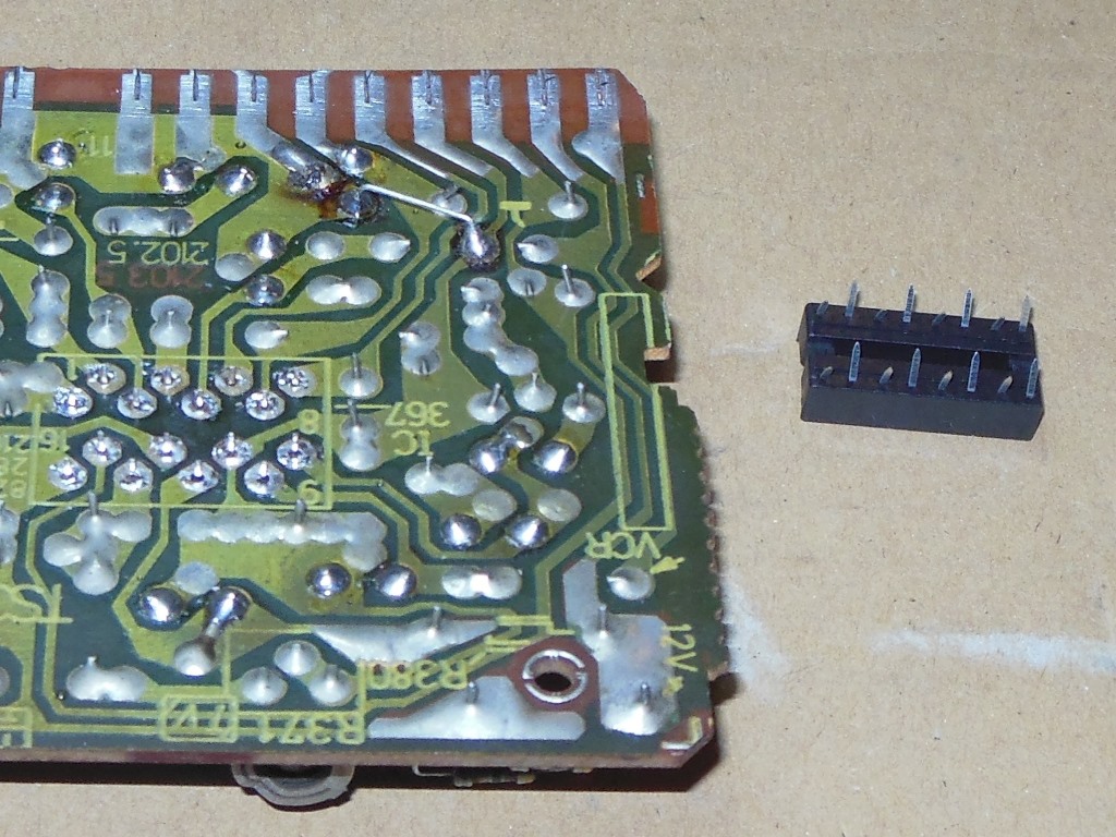
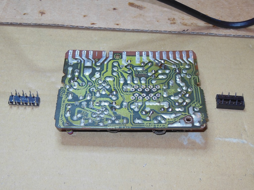
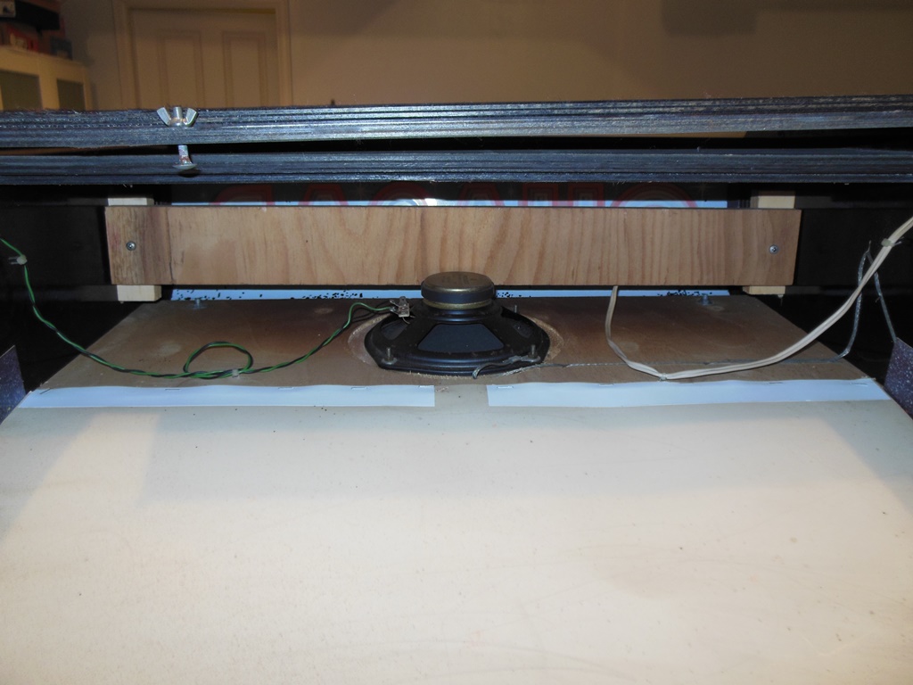
The sound PCB was removed from the cabinet for bench testing. As can be seen from the photo, the silk screen layer of the PCB has been printed upside down. Thankfully a copy of the silk screen layer is provided in the service manual.

|
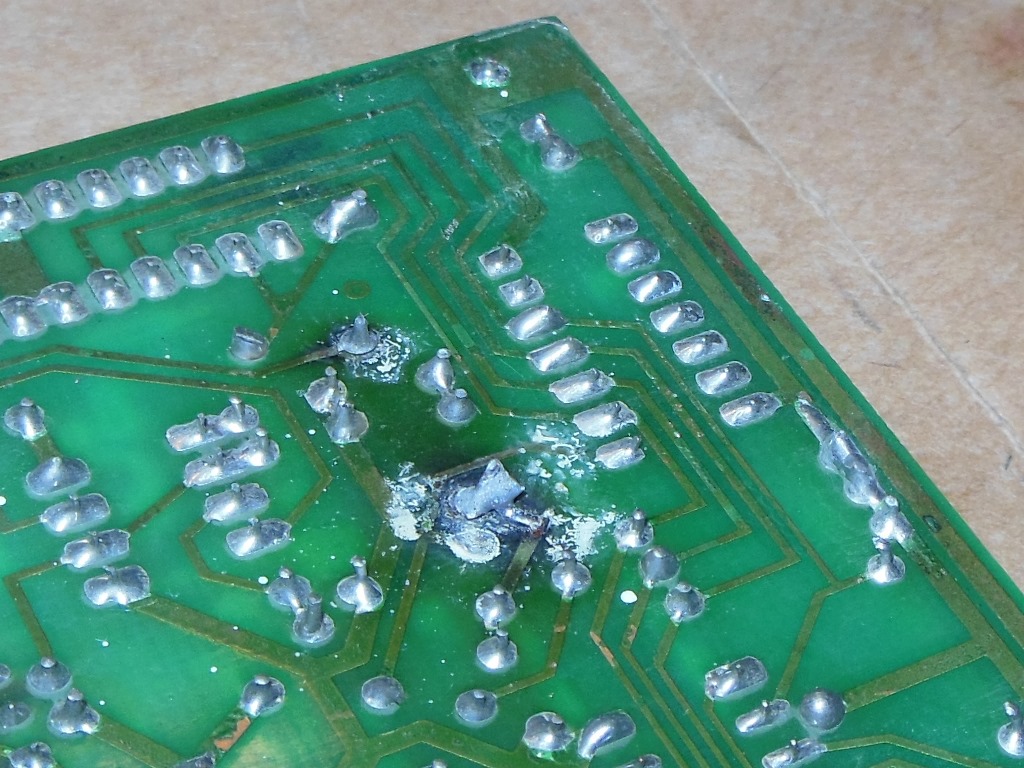
Inspection of the sound PCB revealed some near-dry joints on the power connector and an area of charring around a power resistor. The former I reflowed and the latter did not appear to be open or running hot on the bench now.

|
Testing on the bench using power only adaptor and the built in self-test didn't show any problem with the audio initially, however after an hour the audio had stopped working. This sound board contains a small power inverter circuit that generates -11V from the +12V and it appeared to be working OK as measured on pin 3 of IC 6 (LM1408, DAC). Pin 4 of IC 6 showed reasonable audio output, suggesting the digital section was working. Audio was also present entering and exiting the volume pot P1 and on pin 6 of the TDA1010 power amplifier. The scope also showed a jumpy DC offset on pin 6 of the TDA1010 and I suspected the TDA1010 or 1uF tantalum input capacitor C6 were bad. Changing both the TDA1010 and C6 (replaced with a 1uF none-polarized ceramic version) brought the sound back. No further audio problems were found after several hours on the bench and in the cab.

|
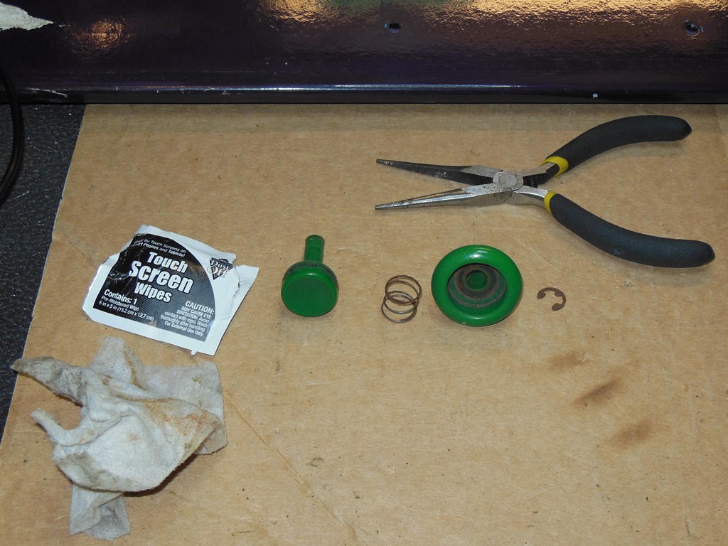
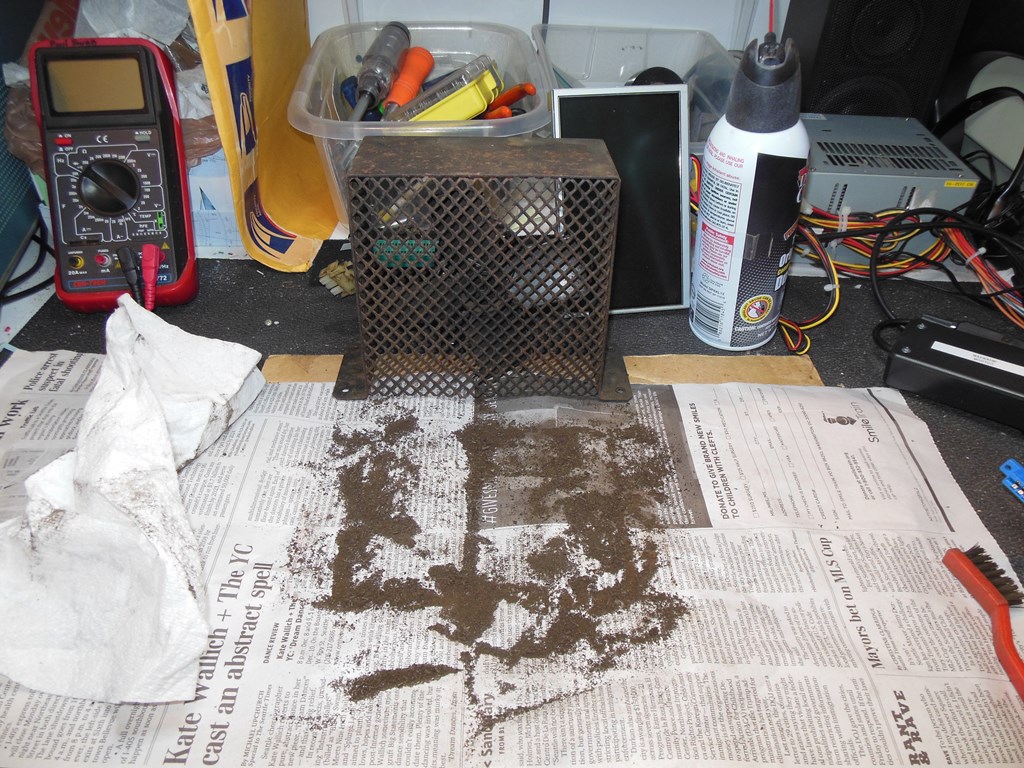
The fans in these early Zaccaria games were usually corroded and worn out thus needing a replacement to be fitted. This example appeared to be dusty but in good condition and working properly. A good clean with a nylon brush and blast with Dust-Off cleaned it up.
|
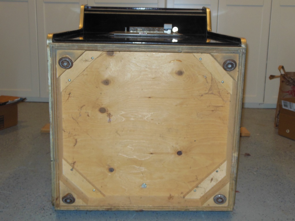
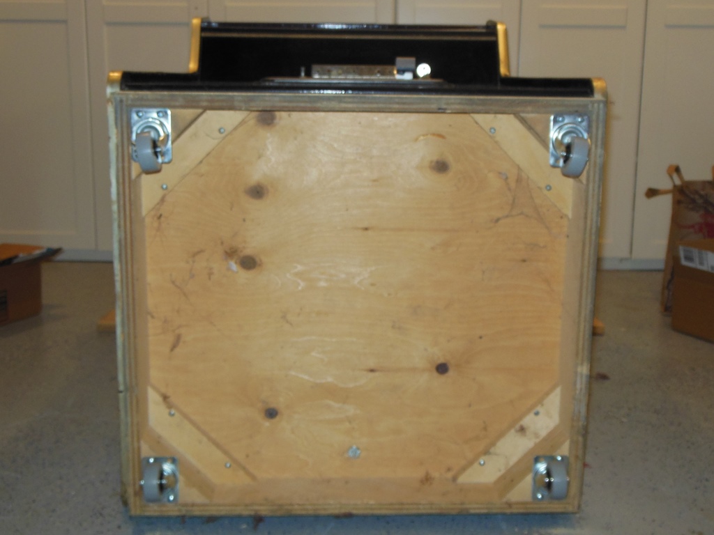
The wobbly feet were replaced with 2" soft wheel castors for ease of transport.

|
After a few more days of testing, the game PCB cover plate and monitor shroud were reinstalled. One final wipe down with a damp cloth completed the restoration.