|
|
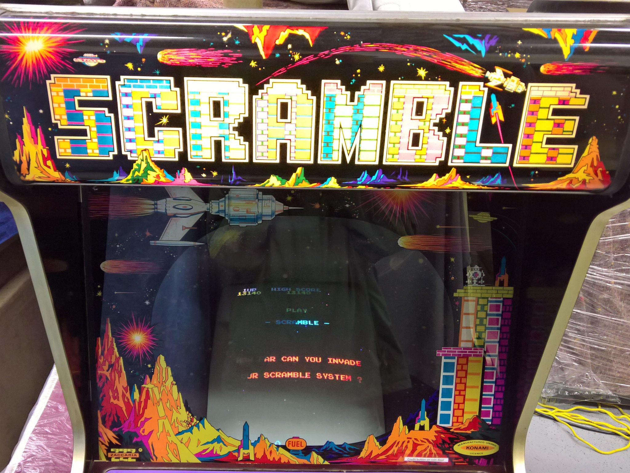
The game was running fine at the show up until Friday mid-afternoon when it was discovered that it wouldn't coin up. Suspecting the credit PCB had failed I swapped in a spare but it still wouldn't coin up. Swapping in a spare game PCB still didn't fix the coin up issue. The game was turned off and I brought the credit PCB's home with me to test out.
|
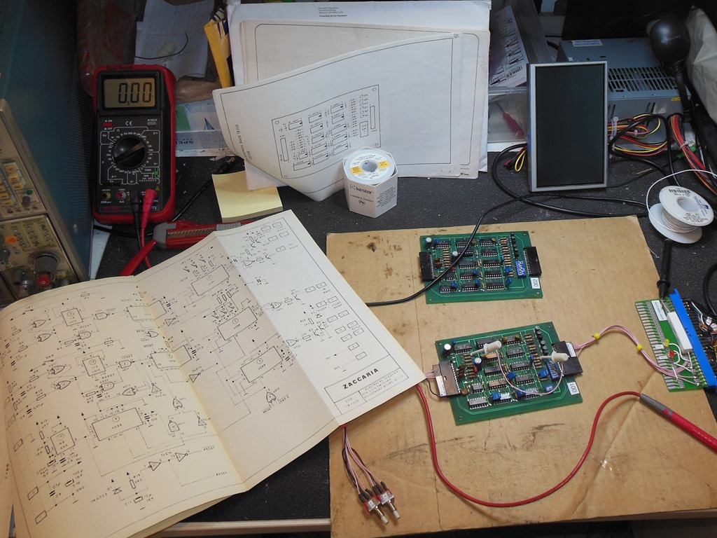
Testing the 1B1145 credit PCB on the bench confirmed that it wasn't working (and neither was the spare). With limited time to investigate, my first thought was to add a simple strap from the coin input switch to the credit output, effectively bypassing the credit circuit. This worked OK on the bench but I was suspicious that the entire CMOS implementation was because the board ran off +12V in the cabinet. Checking the manuals confirmed that the credit board Vcc was +12V so connecting the coin switch, that was pulled up to +12V, directly to the game PCB coin input risked blowing the input and thus was abandoned.
I decided to go with leaving the credit PCB out altogether and adding a strap directly from the coin switch to the credit pin on the connector. This got the coin-up working again and aside from the failure of the marque light the game ran through to the end of the show OK.
|
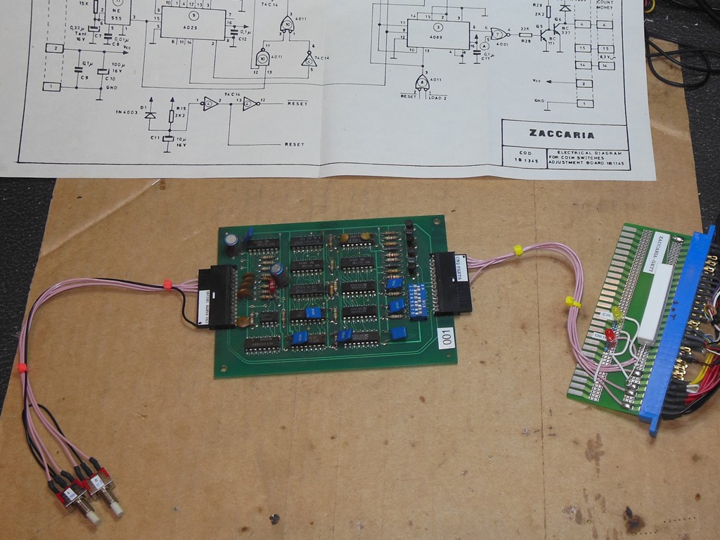
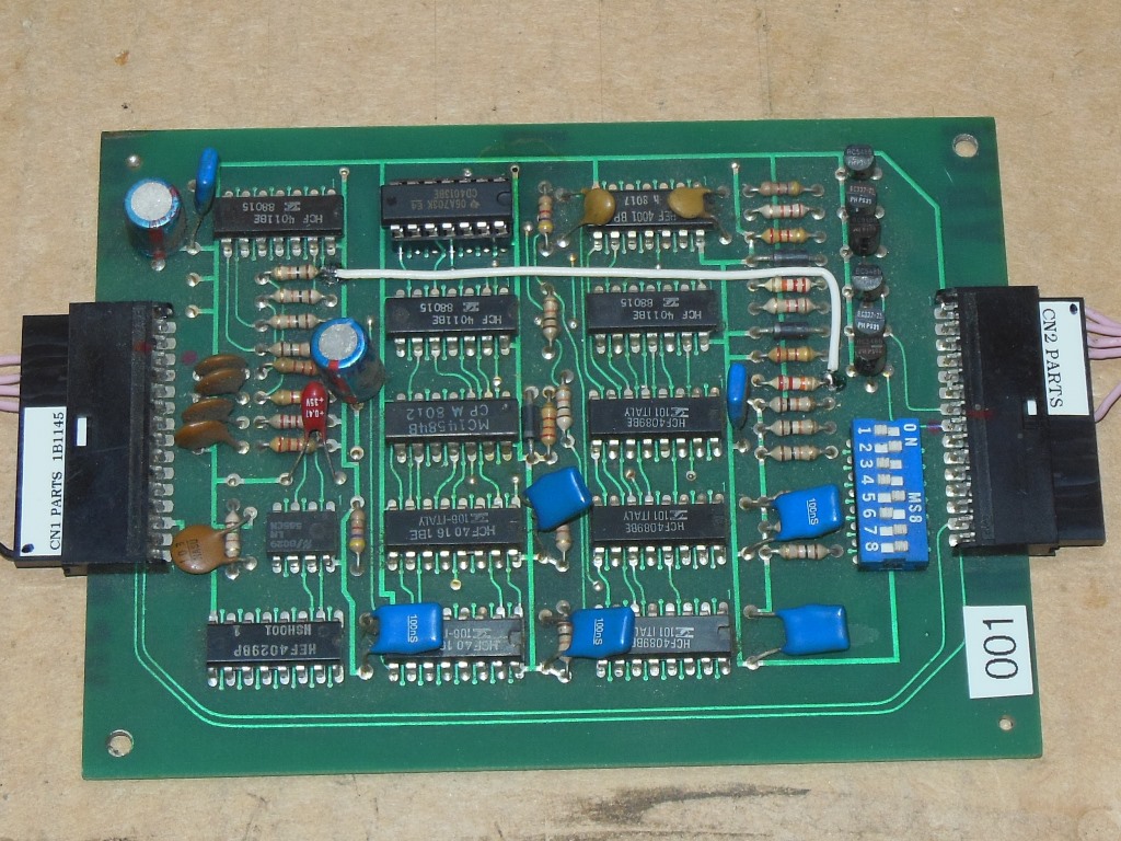
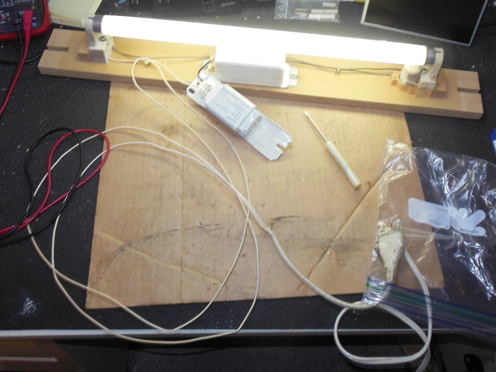
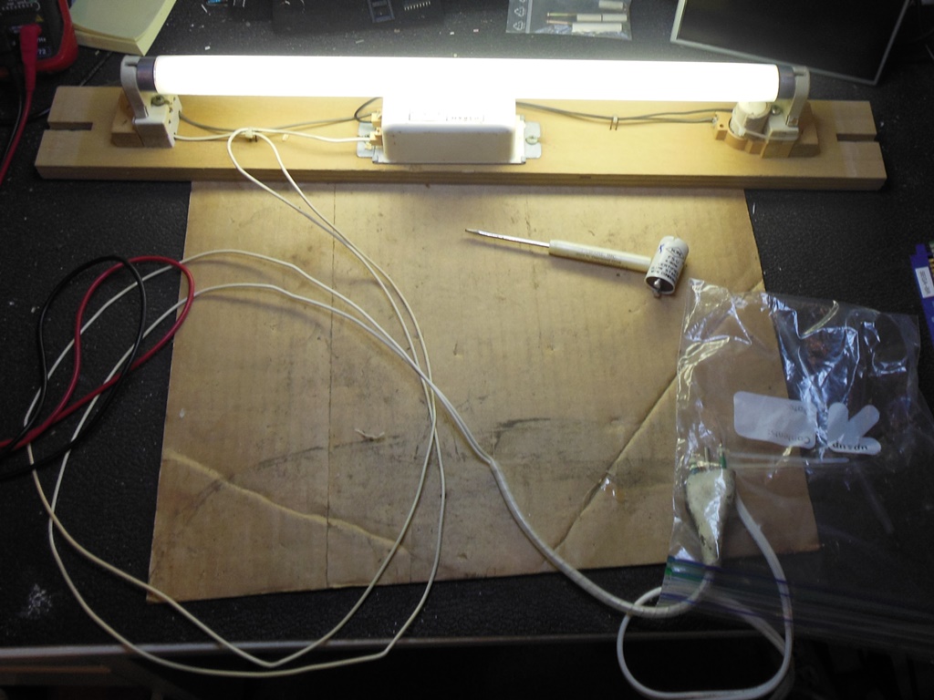
The Zaccaria 1B1145 credit PCB is an awkward thing to work on. It is all CMOS necessitating a set of spare parts just for it (some of which are hard to find) and difficult to debug being all one-shot logic. Since I don't operate games commercially I only need 1 coin 1 credit so I decided to come up with a simple strap to bypass as much of the credit logic as possible.
|
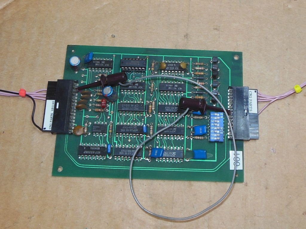
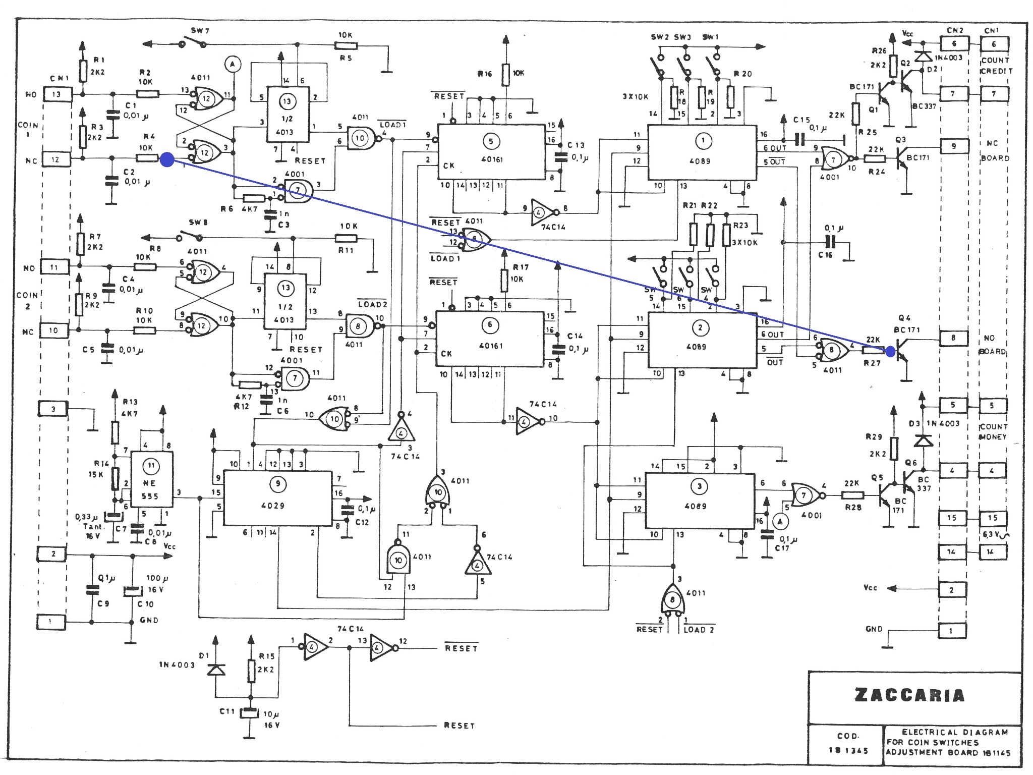
The strap idea I came up with linked the NC (normally closed) coin switch input to the credit drive transistor. The strap linked the IC 12 (4011) pin 1 side of R 4 (10K) to the Q 4 (BC 171) base side of R 27 (22K). In the idle state the NC switch is closed and thus pulling down the Q 4 base (off). When the NC switch is open (coined) R 3 pulls up the Q 4 base via R 3 (2.2K) and R 4 (10K). Since R 27 (from the credit logic) is still low the Q 4 base voltage from the divider of R3 + R4 + R27 is about 7.7V, more than enough to activate the credit transistor. After fitting the strap on the two PCBs on the bench the strap worked fine on both faulty boards.
|
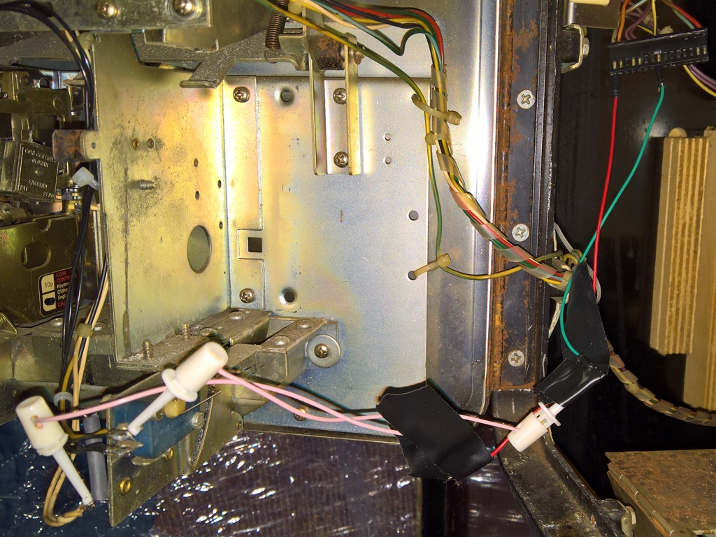
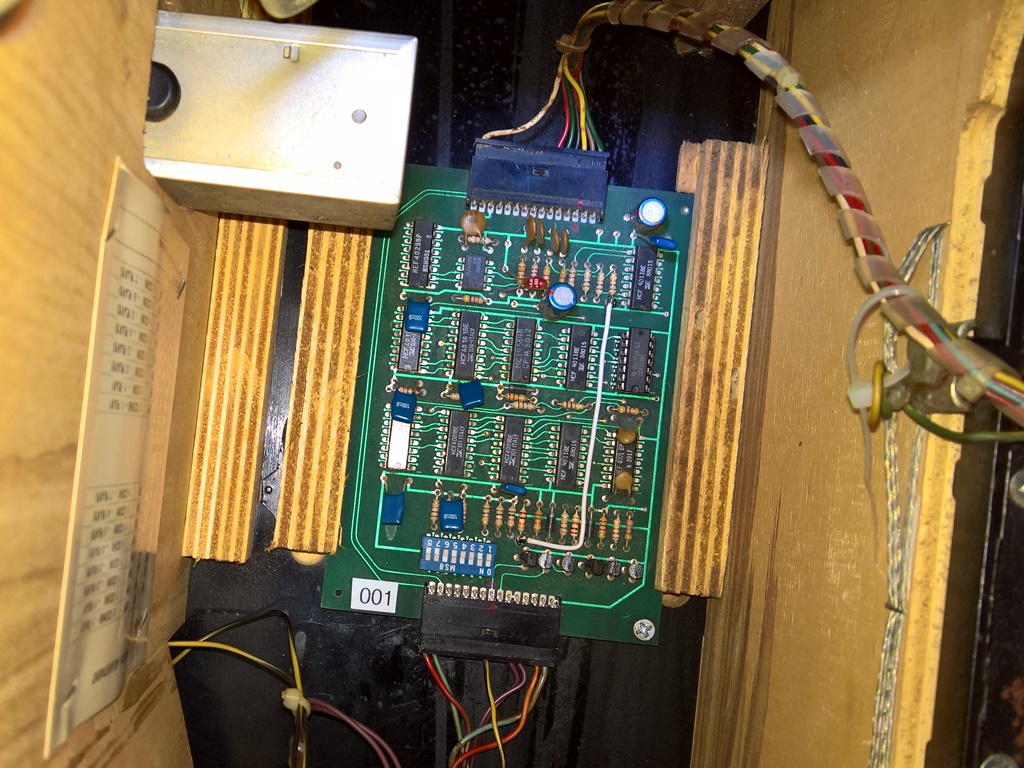
The original MacGyver fix for the credit board at the show involved jumper wires in connectors and probe clips on the coin switch held in place with electrical tape. All that was removed and the credit PCB refitted. The strapped credit PCB worked without issue in the cabinet.

|
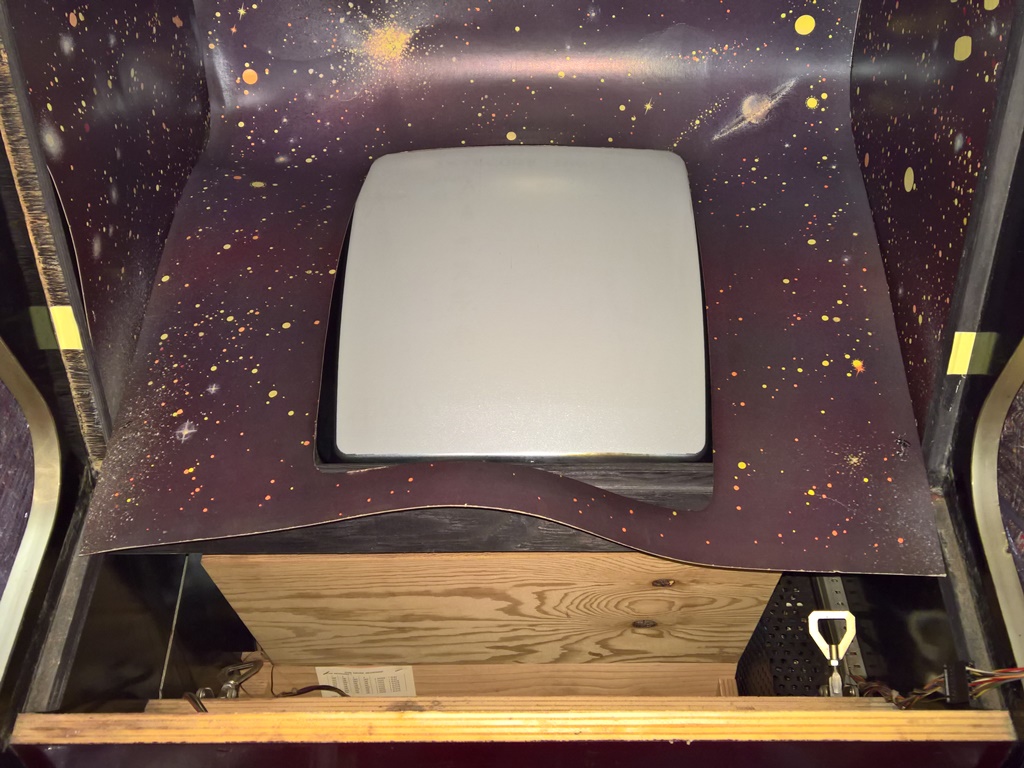
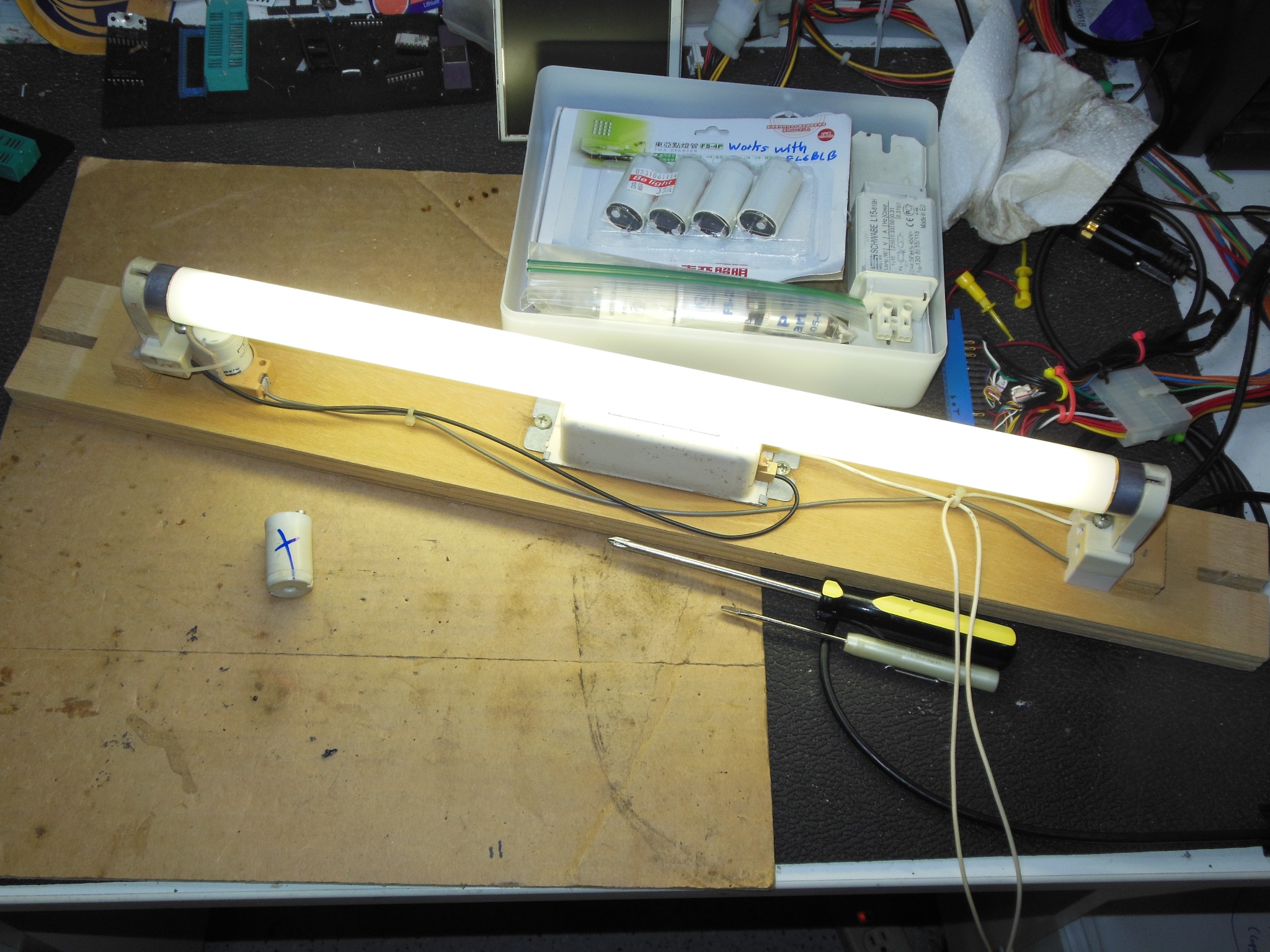
The marque light had failed at the show. Since the marque itself cannot be removed from the outside, the marque assembly must be removed via the rear access hatch. There isn't quite enough room to undo the rear access hatch wing nuts without risk of creasing the monitor surround, so in order to make space to undo them the surround front staples are removed and the surround slid forward (that itself requires the control panel & monitor glass to be removed). Thus it's quite a bit of effort to simply change out the marque light :|
|
Since there was no life at all, no flickering or dim light, I suspected a bad ballast. I wired in a spare ballast and discovered that there was still no life. Fitting a new starter brought the light to life with the new ballast and swapping back to the old ballast found it also working. The light ran fine on the bench for a few hours.


|
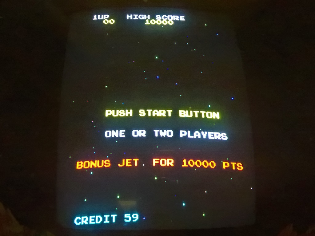
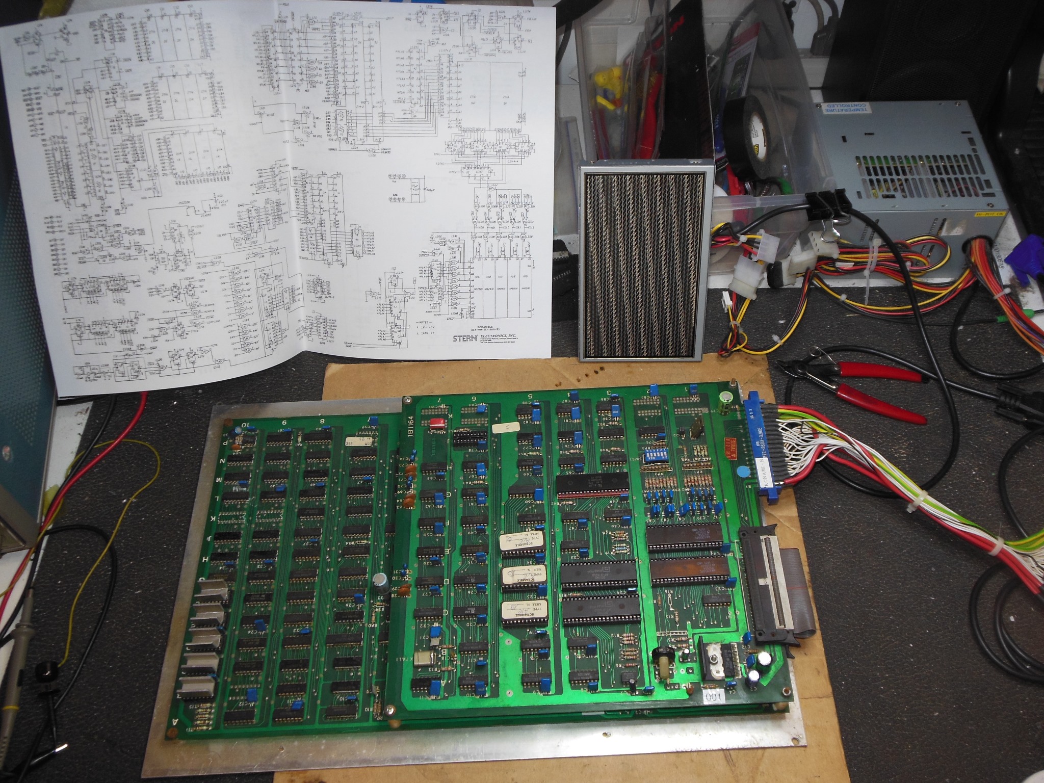
After a few minutes of pre-show testing the monitor lost sync but the game still appeared to be running. After a power cycle the monitor came up white screen but the game still coined up and appeared to play blind. I suspected the Philips KT-3 monitor sync PCB had failed but also removed the game PCB for testing as well.
On the bench the game PCB was working OK with no problems with the picture or sync so I suspected that the TDA2571AQ on the monitor sync PCB was bad (a common failure on this chassis). Replacing it and retesting in the cabinet confirmed the sync PCB was fixed and the picture looked good.
|
Testing of the spare Zaccaria Scramble PCB found it to be not booting with no sync. Inspecting VBLANK at IC 6P (LS08) pin 13 found it high and inactive. Working back to IC 9M (LS74) pin 9 output was high and pin 8 output low. On the input side pin 12 was high and pin 11 active with a clock. Moving on to IC 9L (LS10) output pin 8 was high with input pins 9,10,11 all low with pin 9 having a 0.5V high pulse on it. Checking IC 8L (LS161) outputs 11,12,13,14 were all low with input pin 2 clock active and pin 10 active. At IC 7L (LS161) all outputs were active so I suspected IC 8L was bad. Replacing 8L (LS161) fixed the sync and the game ran OK for several hours on the bench

|
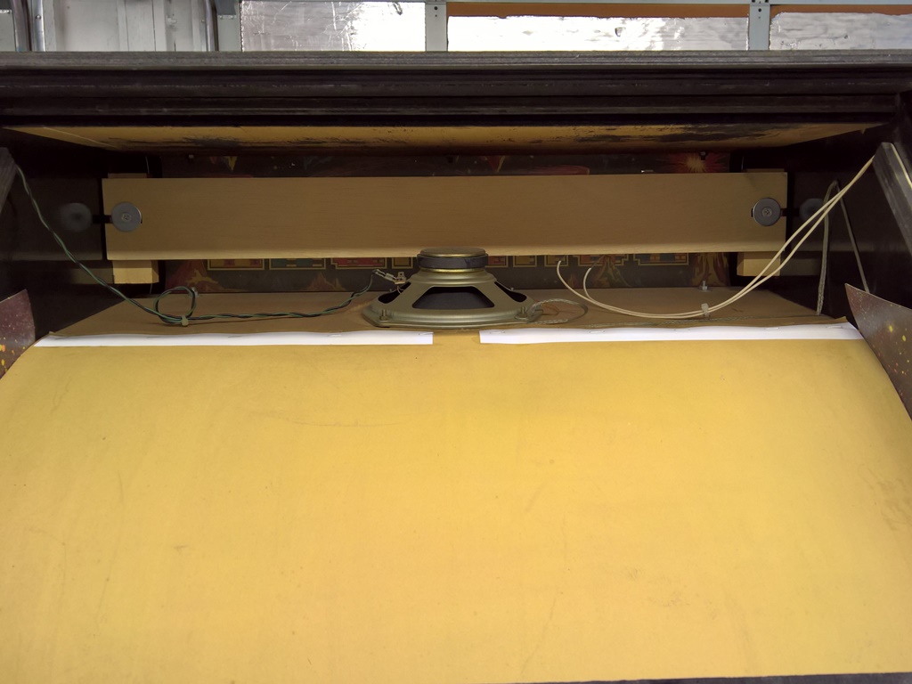
Power-on for the test of the monitor repair found the marque light not working again. The monitor surround was unstapled, pulled forward and marque light assembly removed through the rear hatch.

|
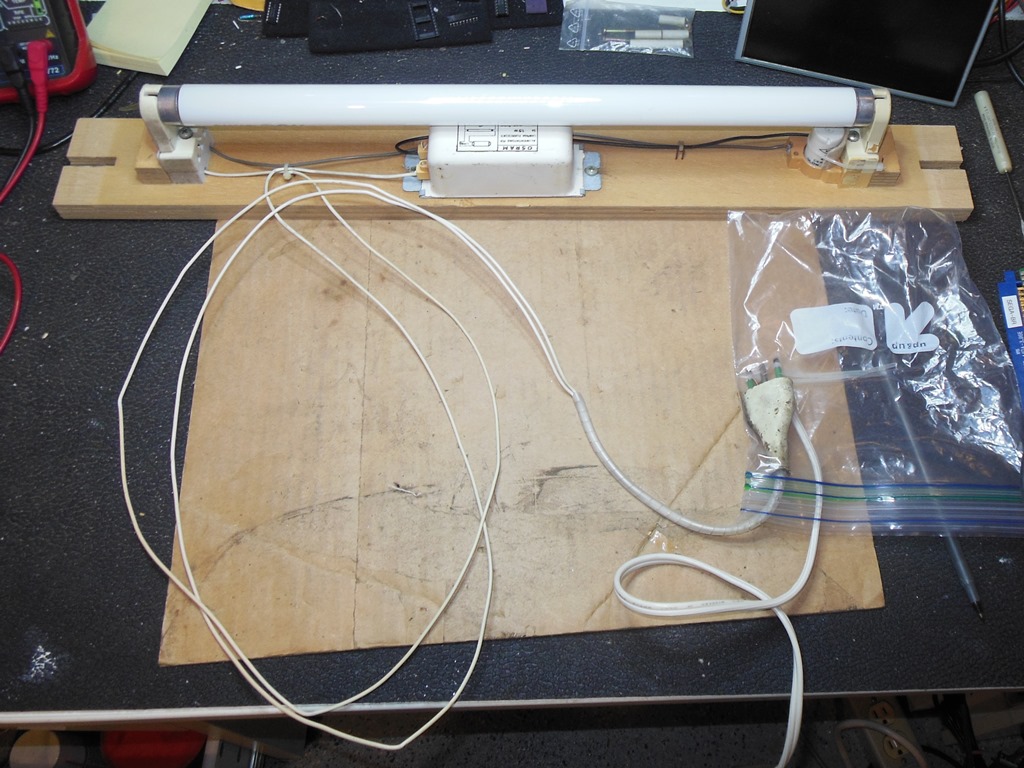
The marque light assembly was an older version from an Astro Wars that had 3-pin power connector. To allow this to plug into a 2-pin travel adaptor I drilled a small hole in the adaptor (the center ground pin, whilst present, wasn't connected to anything on the marque light and later models used a 2-pin power plug). The marque light was still dead on the bench and there was no glow from the starter. Replacing the starter fixed the light.
|
Back in the cabinet the marque light was working OK as was the rest of the game for several hours.