|
|
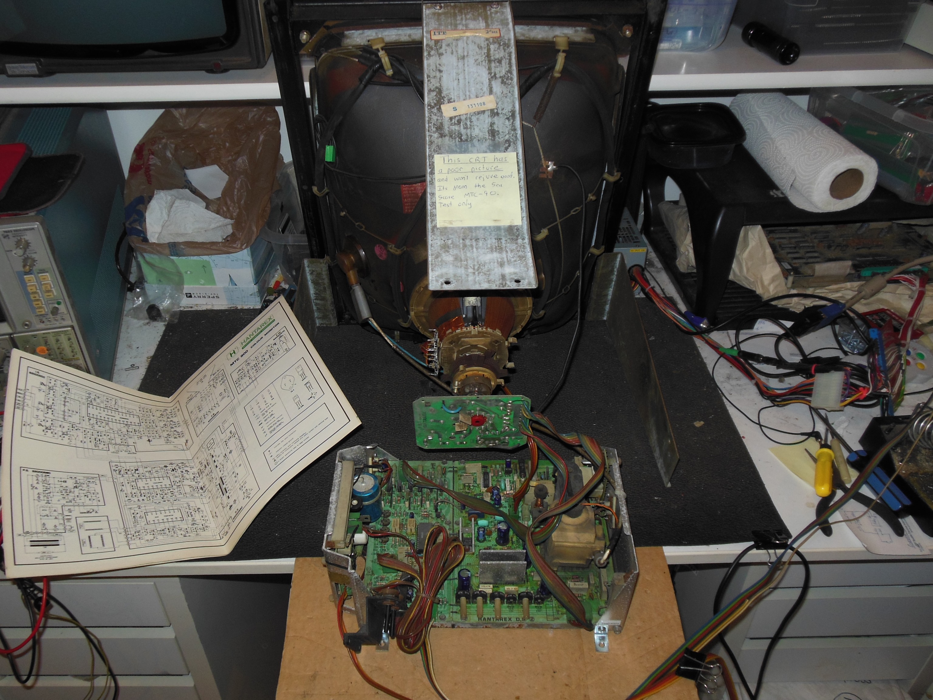
During pre-show testing after several hours the game had no picture. The game was playing blind and the monitor had neck glow and HV. The monitor chassis was removed for inspection. Suspecting a common failure in the blanking transistors TR1 (BC237) or TR8 (BC237), these were removed and tested but both tested OK.
|
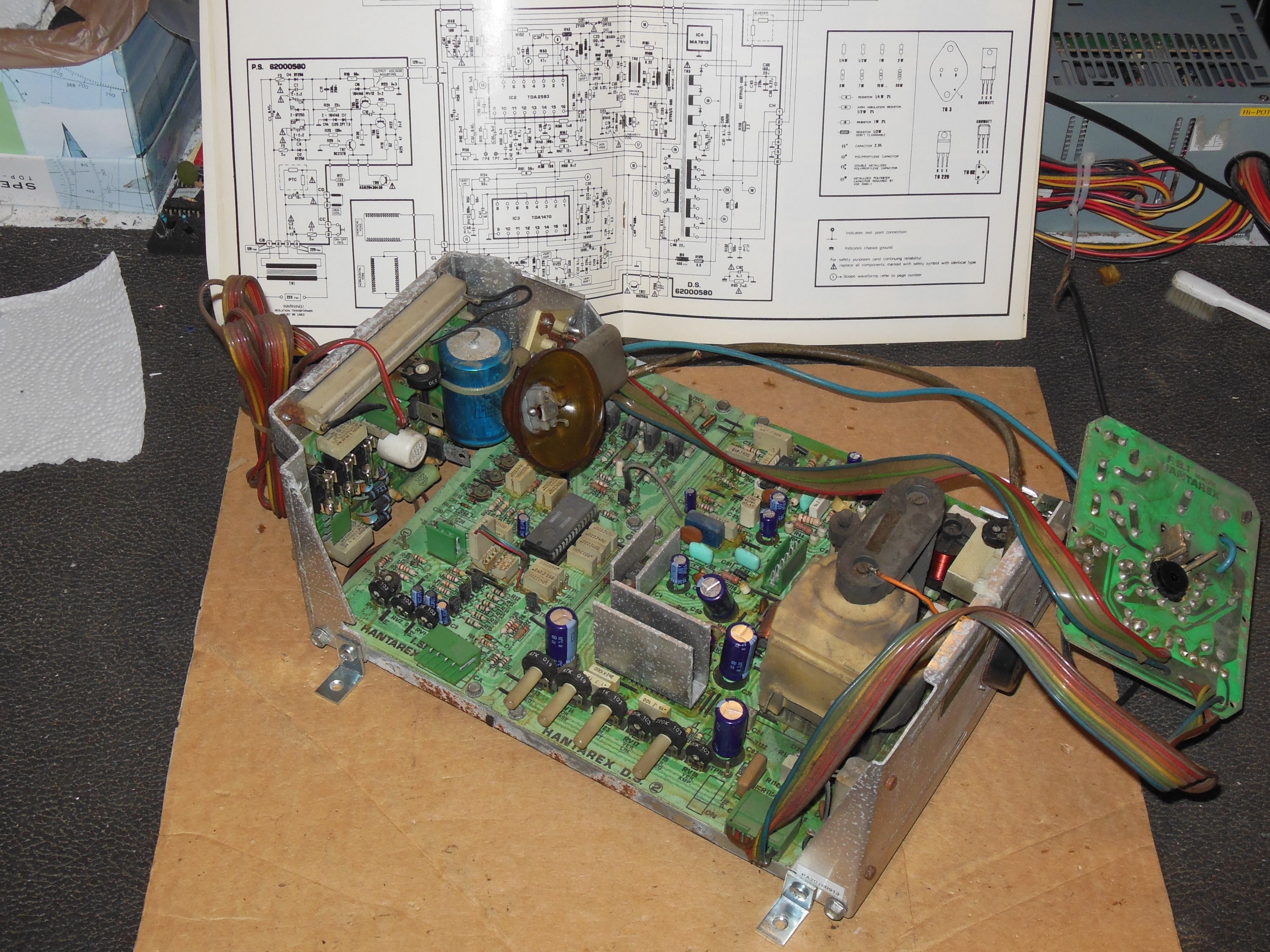
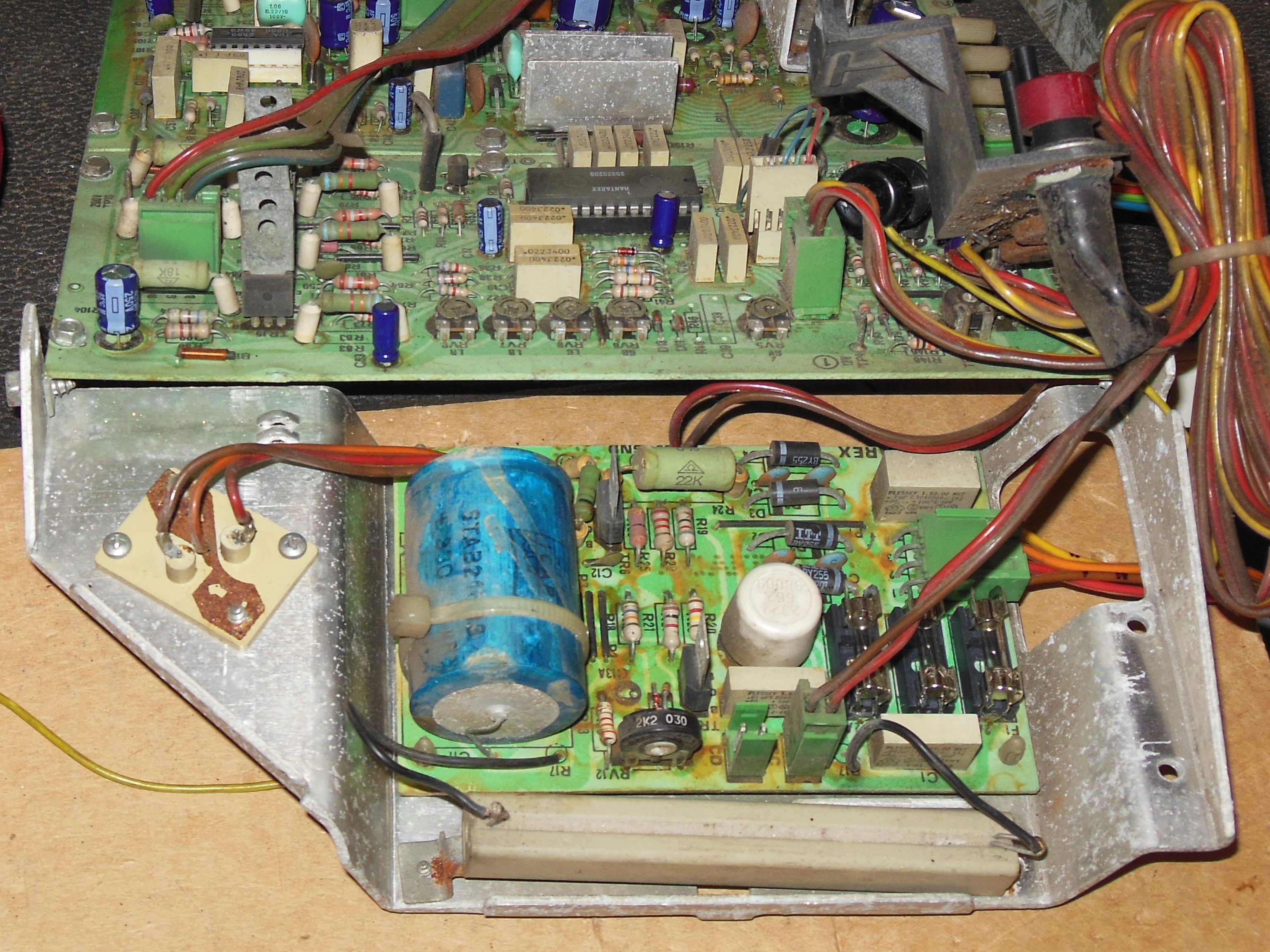
Whilst setting up on the bench I spotted diode D10 (1N4148) was shattered. Replacing it didn't make any difference. Checking IC 1 (TDA 3501) input pins 12,13,14 had signal but the output pins were all idle. The blanking input did appear to be running OK, consistent with the two blanking transistors that tested OK out of circuit. Replacing IC 1 didn't restore the picture. Looking at the pins of IC 1 found Vp pin 6 at 1V whereas it should have been +12V. Checking the +12V regulator IC 4 (7812) found +14.2V on the input but only 0.6V on the output. Replacing IC 4 (7812) brought back 10.7V at the output from 12.3V at the input, still not a solid +12V but enough to produce a poor, barely visible picture with squashed geometry.
|
The 200V test point TP10 measured 165VDC and the 128V measured 107VDC. The B+ adjustment pot had no effect indicating a fault on the power regulator board. Both back-to-back diode checks and out of circuit Hfe checks passed on all the transistors but a close visual inspection identified diode D5 (1N4148) was shattered. Replacing D5 and reassembling the chassis found B+ voltage close to 126VDC and it was set at 126VDC. Picture quality also looked good.
After several hours on the bench the picture became a bright white raster. IC1 (TDA 3501) was very hot. The socket looked poor and was replaced but IC1 was still hot and still white raster. Replacing IC 1 (TDA 3501) brought the picture back and the chassis ran on the bench for several hours without issue.