

The Northwest Pinball and Arcade Show secured a seminar from Warren Davis, the creater of Q*Bert.

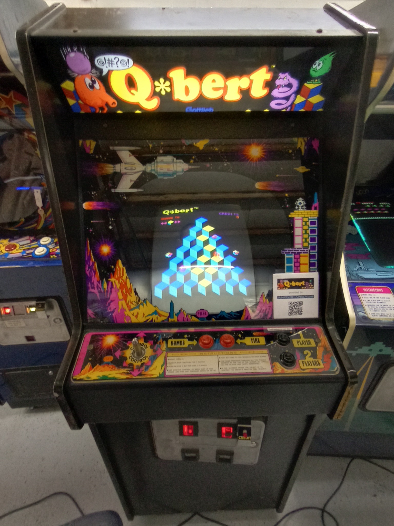
To provide more than one Q*Bert game to play at the show I decided to attempt a temporary conversion of this Super Cobra cabinet to Q*Bert. This cabinet was selected based on it being the most likely joystick assembly to allow a simple temporary 45-degree diagonal rotation. The plan wasn't to use an original Gottlieb PCB set as it's a large awkward board set, but instead to use the compact bootleg single board version loaned to me for the show by Andys Arcade.

|
|
Andy sent me two game PCBs, one of which was working OK and the other had issues. The game sprites were running OK, but it appeared that the background graphics plane was static garbage. Closer inspection found the coin input at least was not working. Attract mode sound was working OK.
Starting with the background graphics issue and using the Gottlieb schematics as a rough guide suggested the background RAM was IC 6L (6116). Checking on the scope found pin 18 "CE" idle low, pin 20 "OE" active and pin 21 "WR" idle high. The lack of a write pulse correlated with static garbage. Signal tracing with a meter found IC 5J (LS245) pin 19 idle high and IC 10G (LS32) output pin 8 idle high. Checking IC 10G input pin 9 was high with low periods and pin 10 idle high. Following the 10G pin 10 back to IC L3 (TC40H138) pin 7 output idle. Speculatively I tried a piggyback of an LS138 and the background was properly displayed. I didn't have any replacement 40H138 ICs, but identified that this low power CMOS version was used as part of the battery backed RAM circuit. Since I didn't need battery backed RAM for the show, I replaced IC L3 with a standard LS138 that fixed the graphics.

|
Moving on to the inputs, there were three LS240 input buffers IC U2, T3 and S3. The selects
for these traced back to IC R5 (LS138):


|
Testing the PCB on bench revealed that the picture was upside down. The cabinet doesn't support monitor rotation so the easiest option was to make a small yoke adaptor to flip the picture.


|
A standard 56-way JAMMA adaptor was cut down to fit an 18-pin edge connector using a Dremel and wired to convert the bootleg Q*Bert pinout to Konami standard.
|
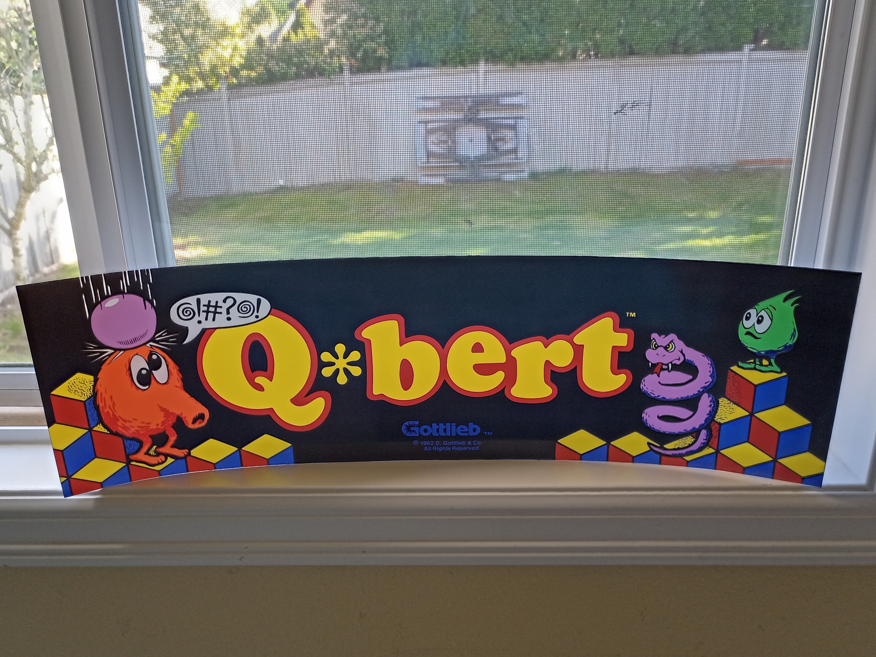
I found a seller on eBay that printed custom-sized Plexiroll Q*Bert marques and ordered a marque to fit the cabinet. A couple of Lexan sheets from Tap Plastics were used to make a sandwich to hold it in the cabinet.


|
Two changes were needed to the cabinet joystick - to rotate it 45 degrees and change the restrictor plate from 8-way to 4-way. There was a wood spacer between the joystick and the panel plate that allowed the joystick to be rotated and then screwed into the wood that worked surprisingly well.

|
The game PCB was too long to fit in the existing board guide, so it ended up resting on a cross member. For the show, it was mounted on a metal plate to sit on the cross member with a screw to hold it in place.

|
Everything was reassembled and the monitor picture adjusted. The game ran and played OK for several hours.