Since it's initial restoration in 2012 the game had run without issue. In the 2019 show I'd noticed the UFO sound wasn't working properly and the picture was a little dim and bleeding. I also didn't have a spare game PCB ready to go for it.
|
|
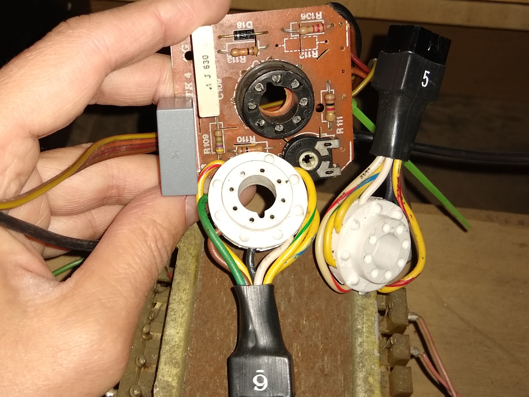
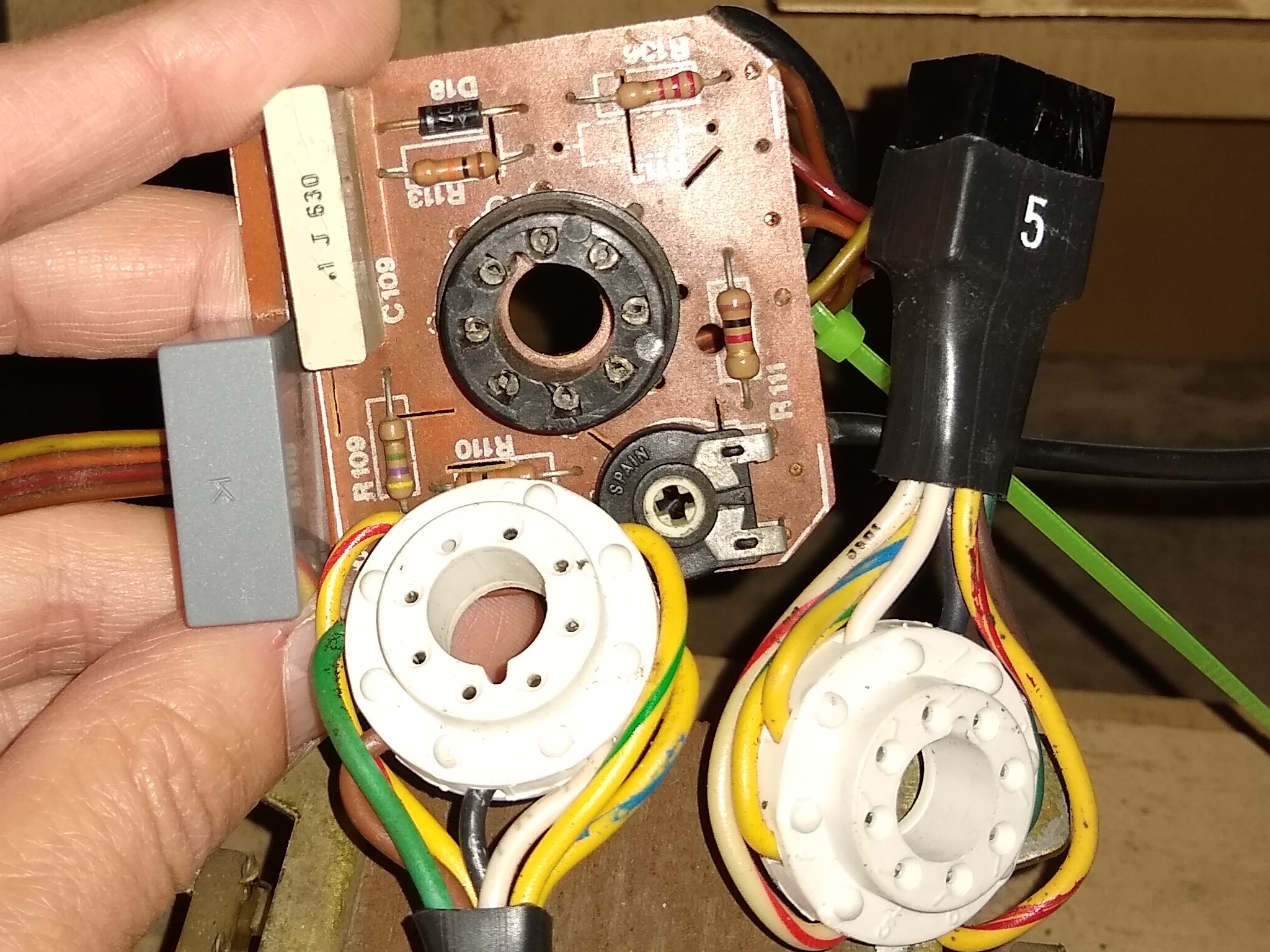
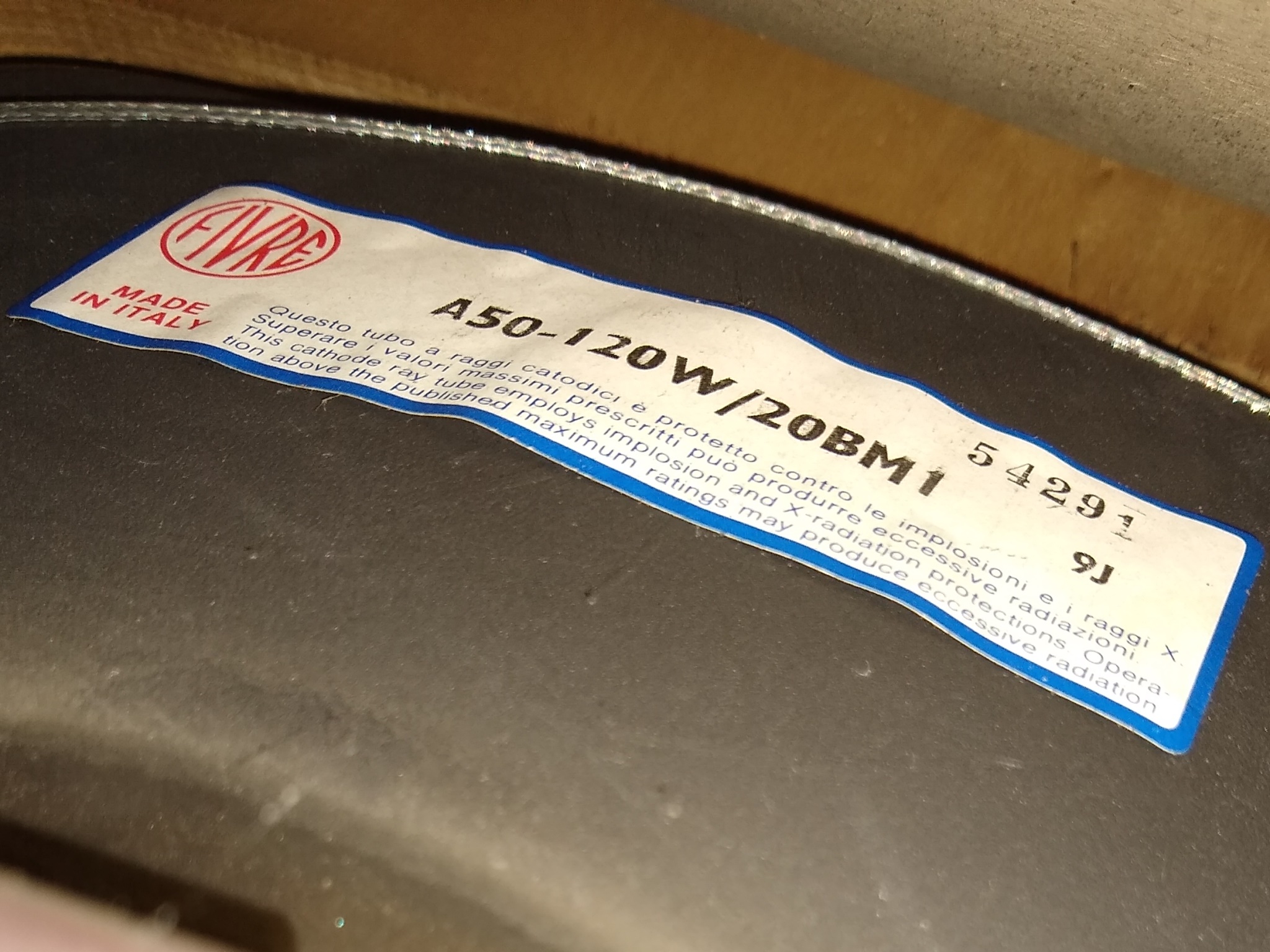
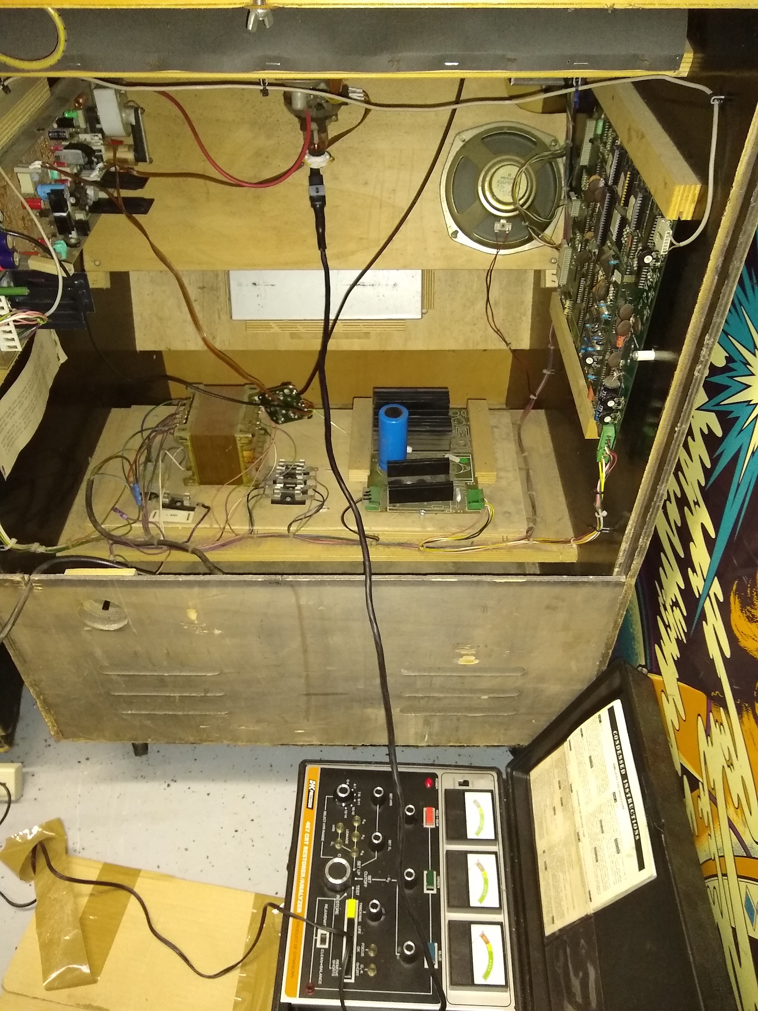
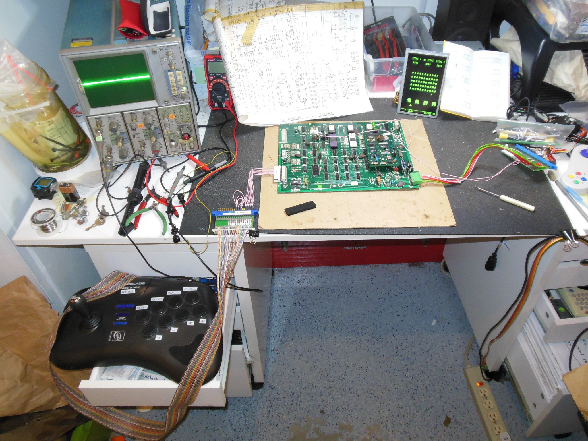
Adjusting the brightness on the monitor caused increased bleeding and not much actual improvement in brightness so the first step was to setup to test the CRT. Looking through the adaptors I found two, 5 and 6, that appeared to have a matching neck socket for this CRT (an Italian FIVRE A50-120W 20BM1). However, the centre of the adaptor socket was slightly too small to fit into the neck plug.
|
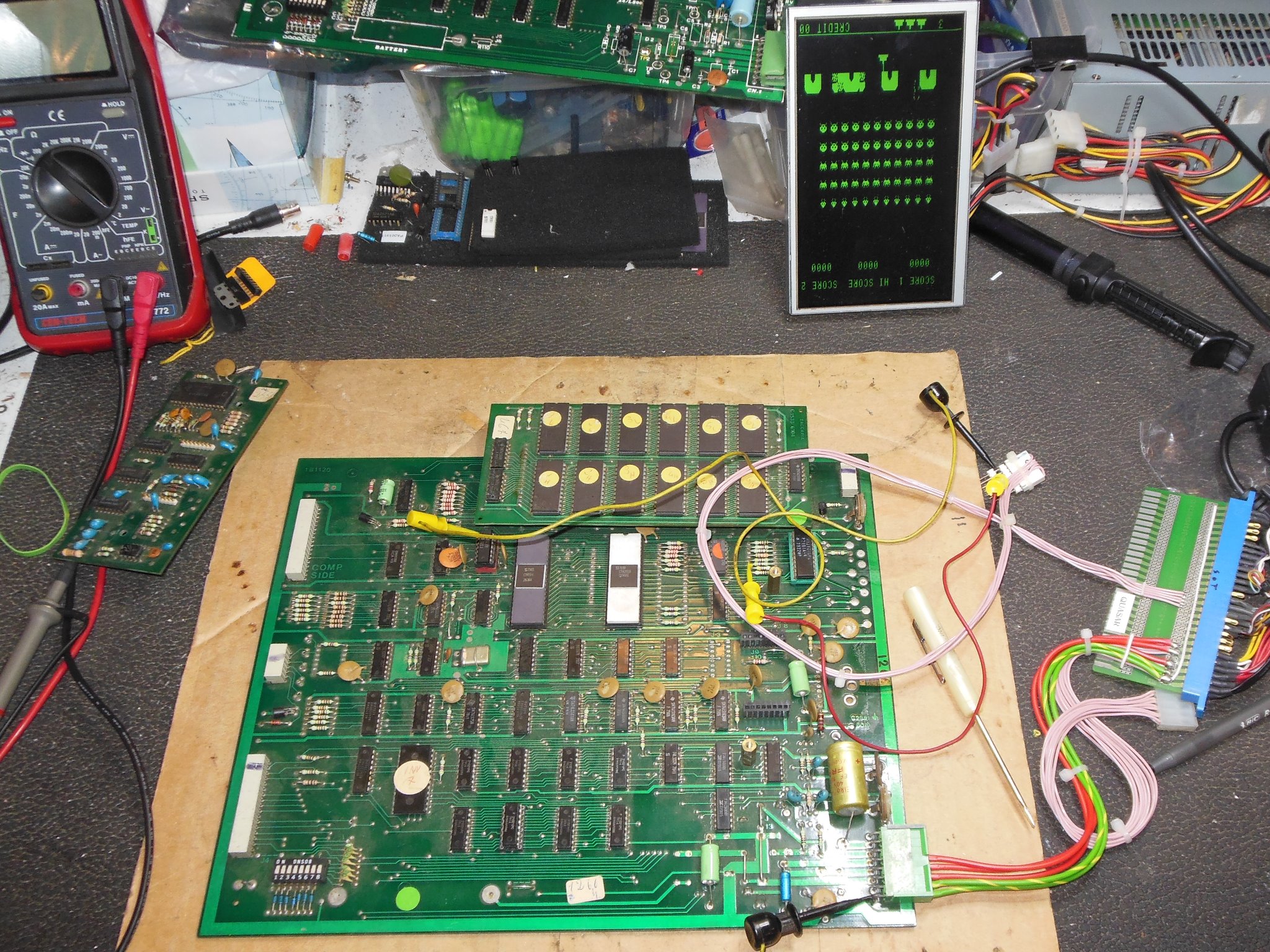
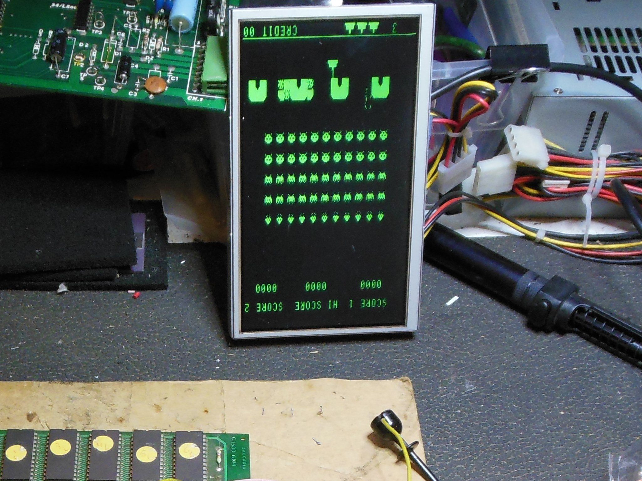
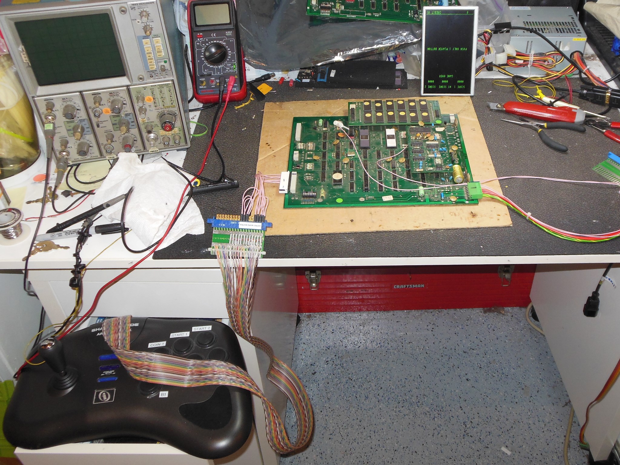
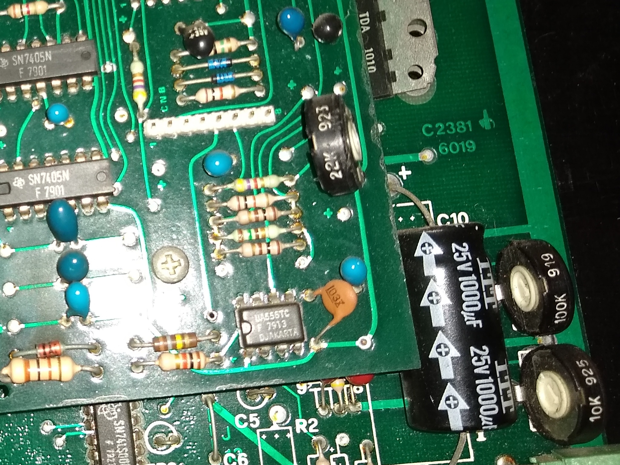
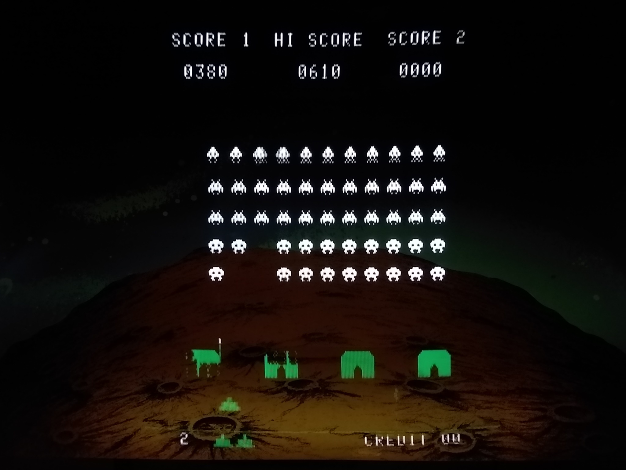
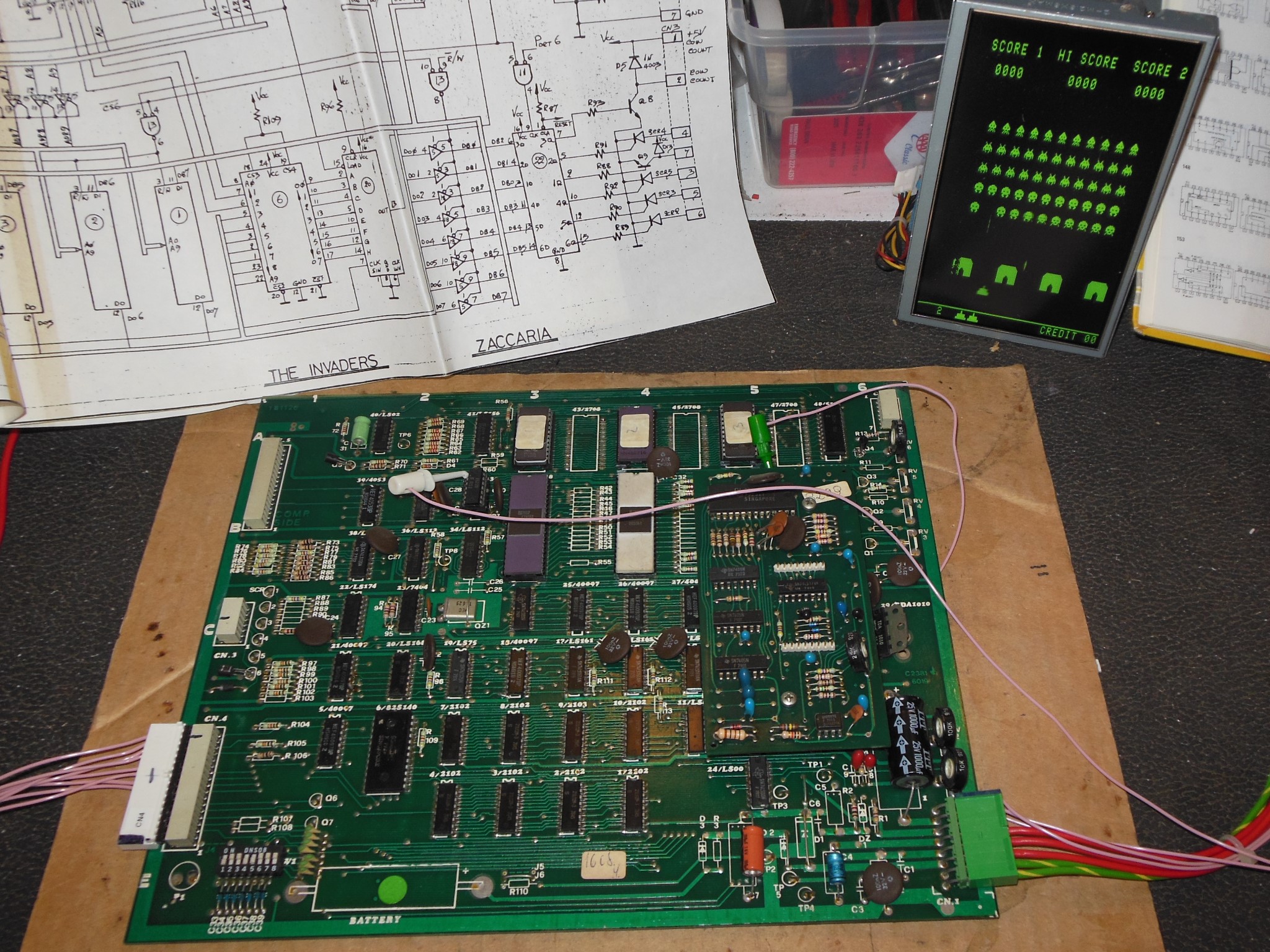
On the bench player 1 start wasn't not working. Both of the player start inputs went to IC5 (45038) pins 12 & 14 and I noticed that pin 12 had solder residue on it, hinting someone may have worked on this fault before. There was also some graphics issues around the base. The game was playing but collision detection didn't appear to be working. Checking the 'PORT 7' (collision reset) signal and collision detect output at IC24 (LS00) pin 3 found them both pulsing during the game.The next step was to add The Invaders to the Arduino ICT to further investigate.
|
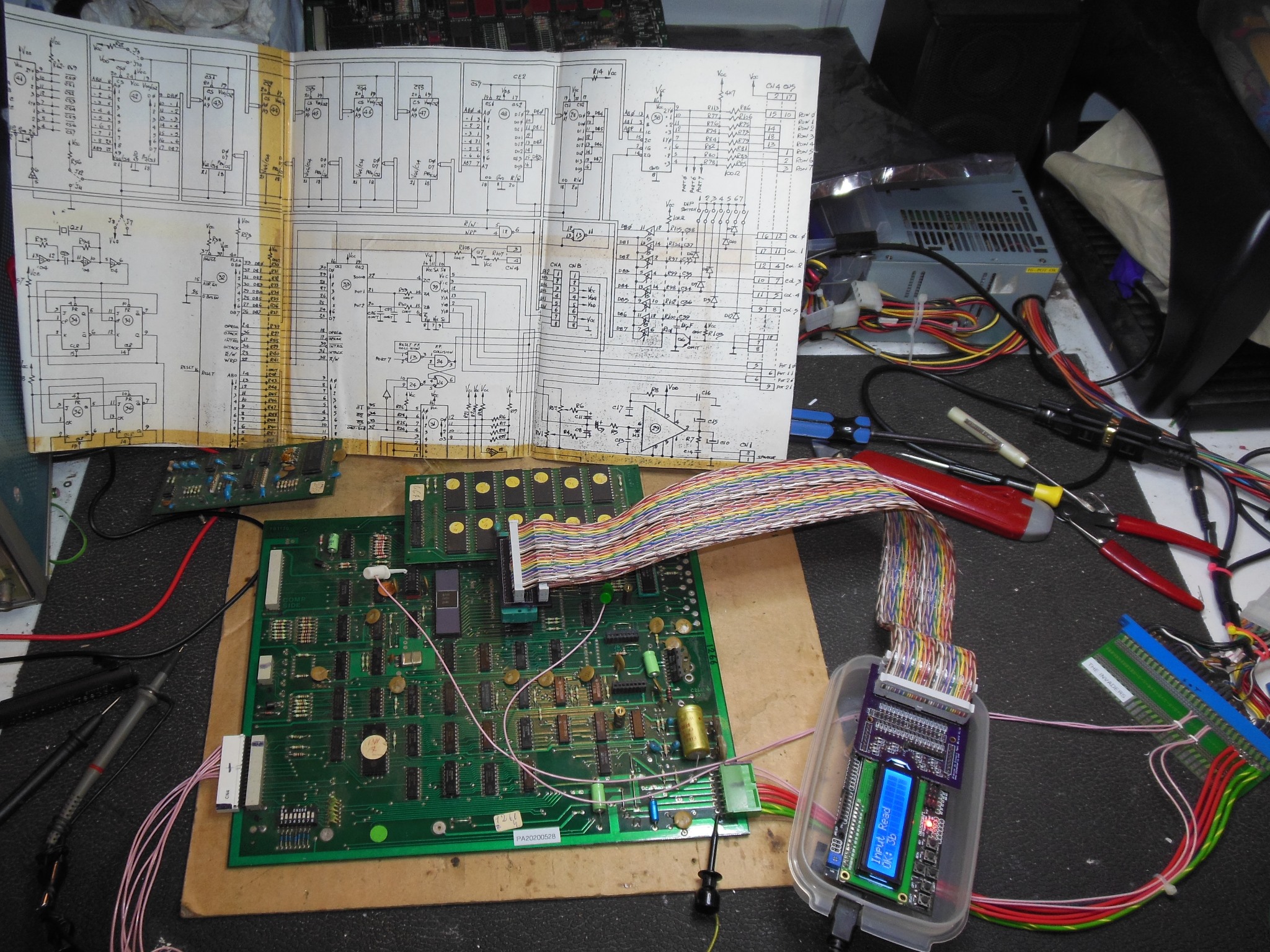
With The Invaders support added to the Arduino ICT the tester reported IC10 (2102) bad. It was at this point I noticed that IC10 served databus bit D0 that was also the same bit used for start 1 and collision detect. Using the scope to compare the data bus bits in CPU idle state found D1-D7 either floating or slightly above GND but D0 was high. Similarly comparing during an active cycle found D1-D7 consistent but D0 looked different with a much harder high. I suspected that something was high overloading data bit D0, not a dead short to +5V because that would cause the game to not boot, but high enough to overload weaker bus drivers :(
The attempt to find the culprit was based on an idle CPU with D0 tied to
GND and measurement of the D0 voltage around the board. The theory was that if enough
current was drawn by the overload there would be a voltage gradient towards it:-
| IC5 | pin 11 | 4.8mV |
| IC5 | pin 5 | 4.6mV |
| IC23 | pin 3 | 4.5mV |
| IC10 | pin 11 | 4.1mV |
| ROM 1H | pin 9 | 3.3mV |
| ROM 6L | pin 9 | 3.5mV |
| 2636 | pin 10 | 3.4mV |
|
A couple of the sound pots and audio amplifier had broken off the spare PCB. The values of the pots were not noted in the schematics and instead confirmed from the PCB in the cabinet. After replacing the sound pots and installing an audio amp the sound was working OK.
|
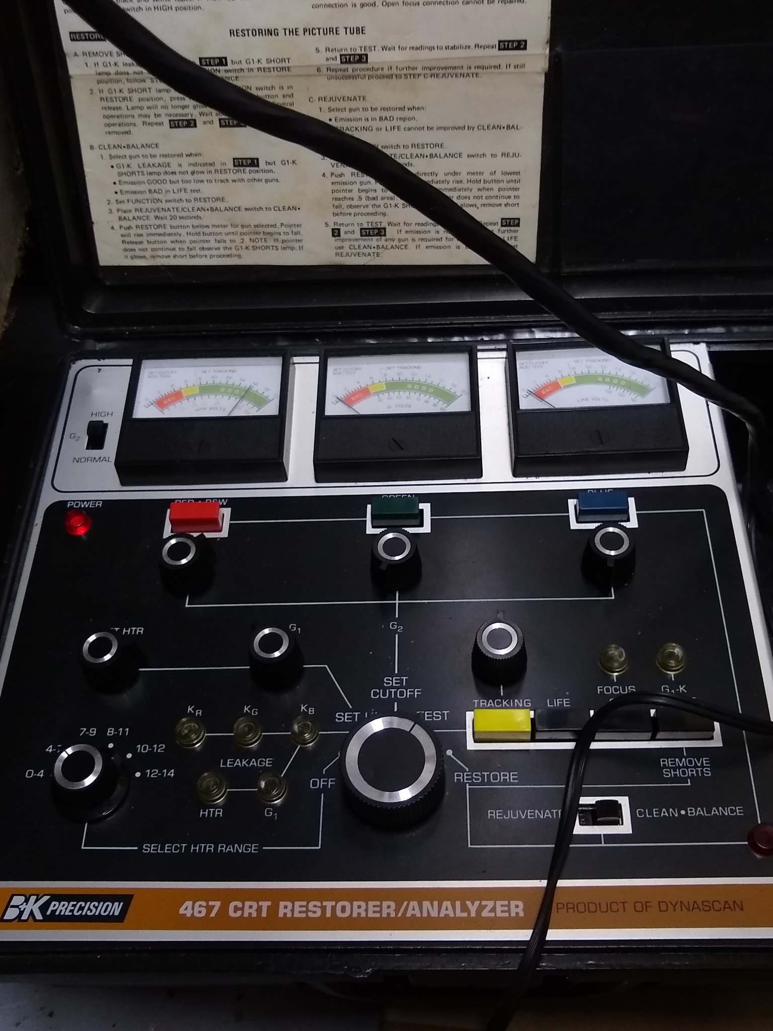
A Dremel with a sanding cylinder attachment was used to slighly increase the centre hole size of adaptor #6 so that it fit on the CRT neck plug. The initial TEST reading was just above POOR and the LIFE reading fell back into the BAD range after a few seconds. A single round of RESTORE with CLEAN-BALANCE brought the TEST reading firmly into GOOD and a GOOD steady LIFE reading. Back on the chassis even the unadjusted picture was brighter with no bleeding :)

|
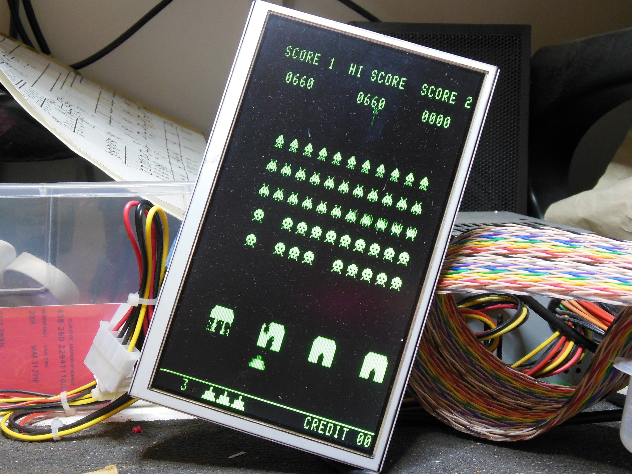
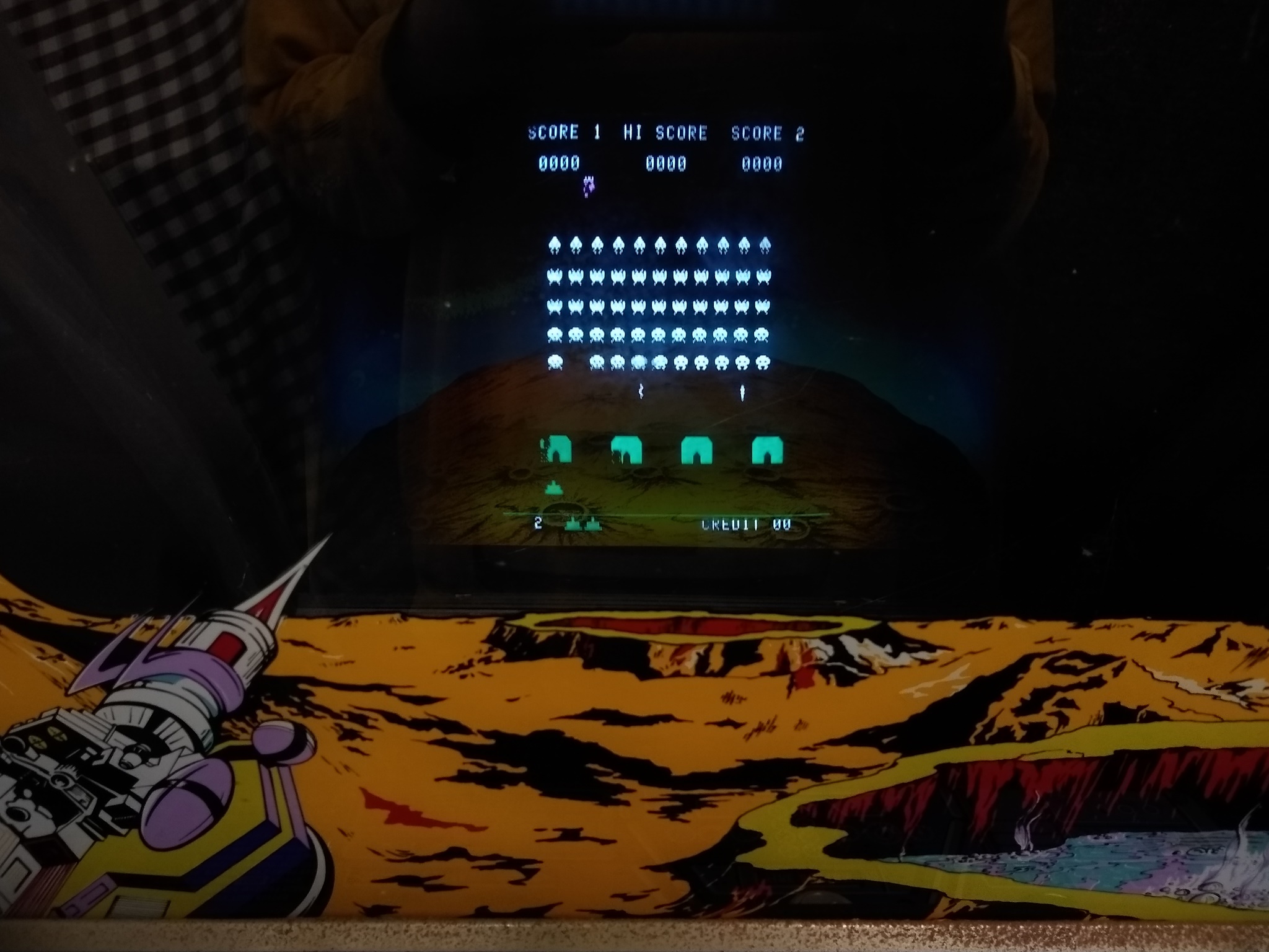
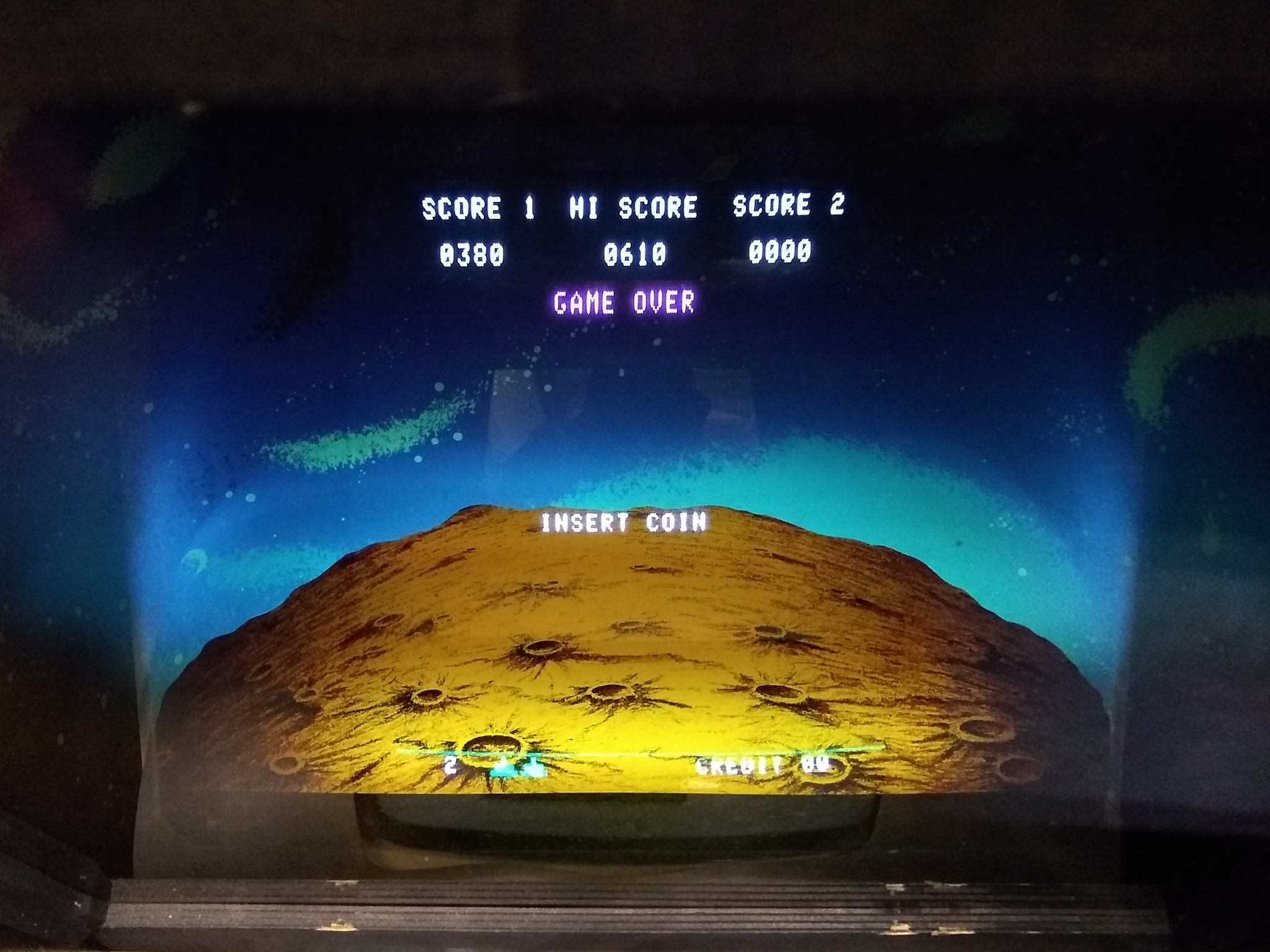
Picture geometry was left mostly untouched to keep it aligned with the coloured overlay. Some minor tweaks to the focus and brightness was enough to get a good picture.
|
The Invaders PCB from the cabinet worked without issue on the bench - the UFO sound was working OK. I cleaned the power pins and exercised the sound pots. On re-test in the cabinet there were no sound issues.