|
|
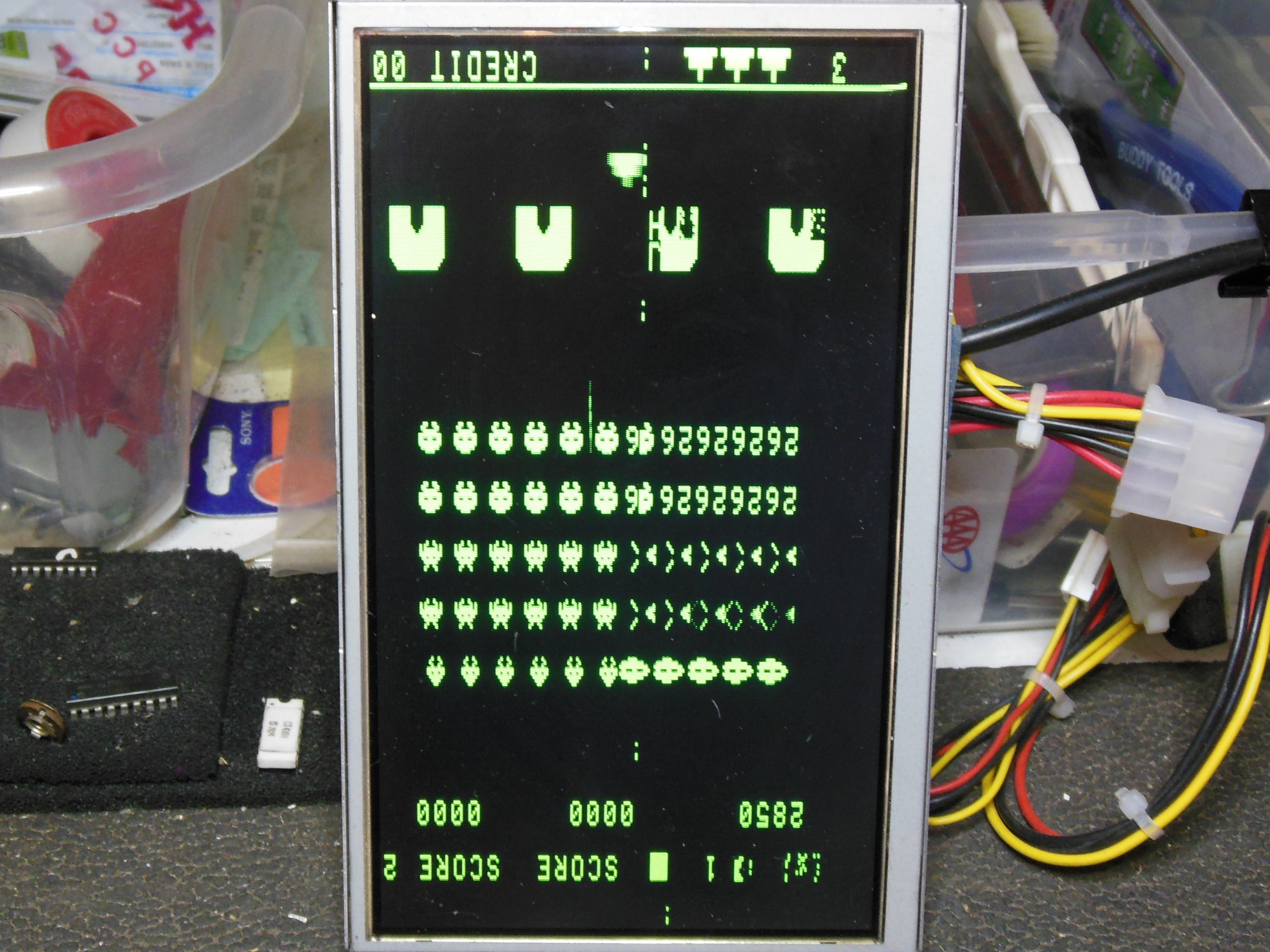
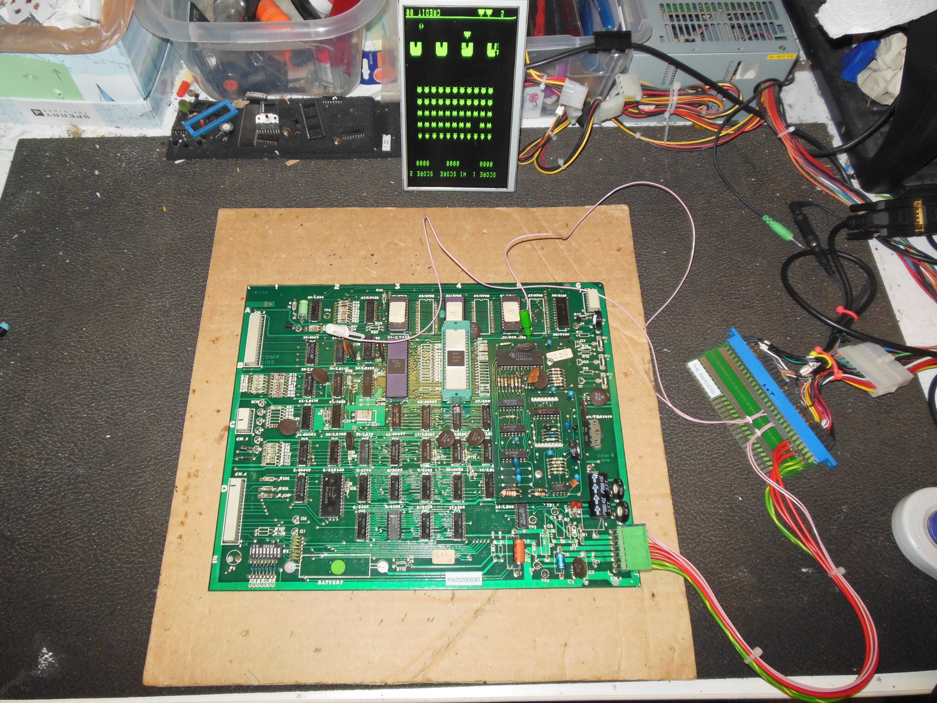
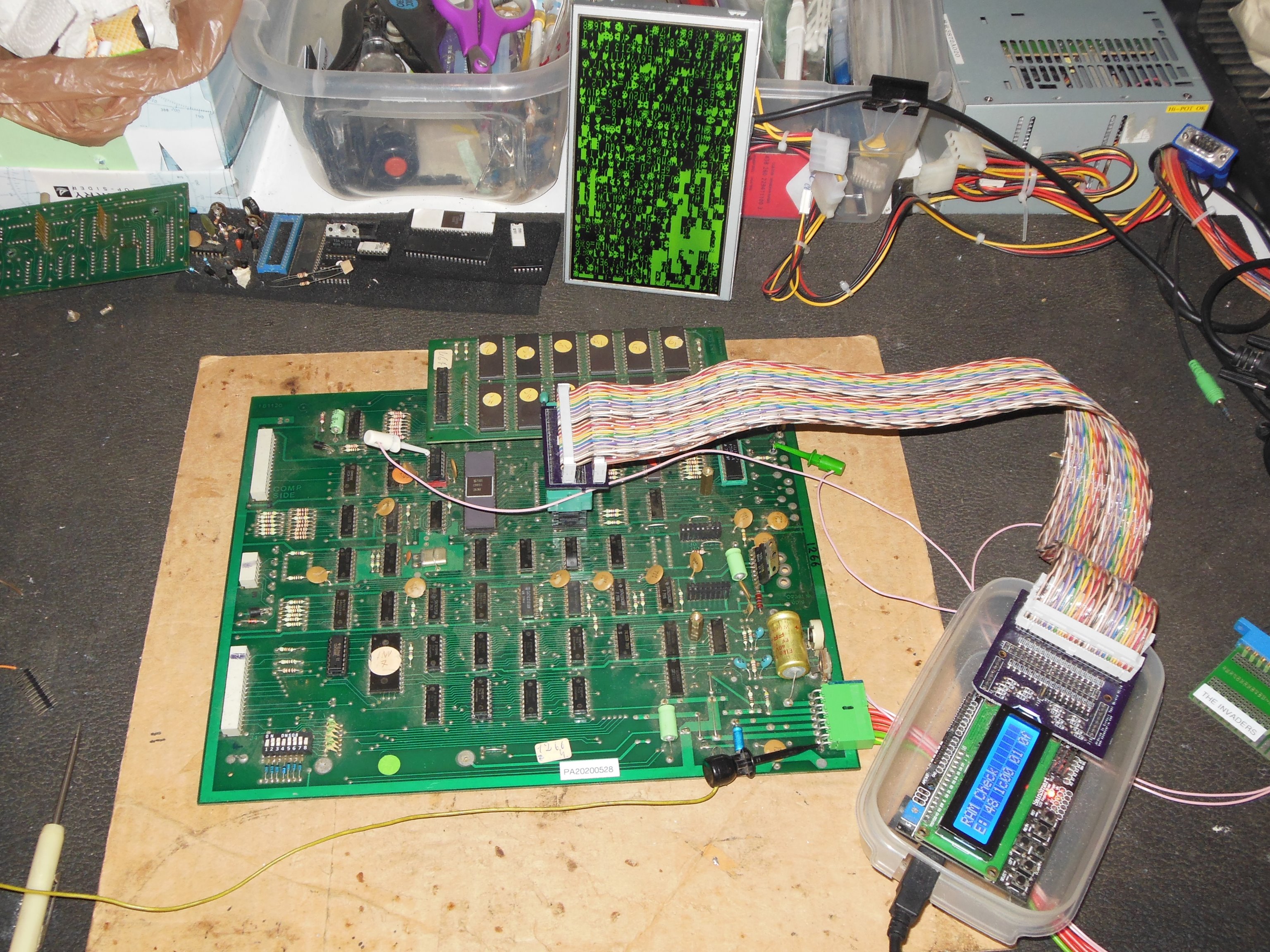
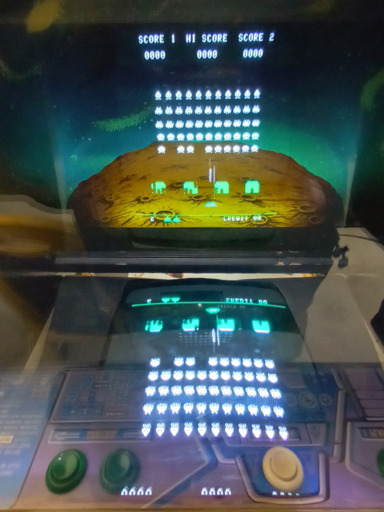
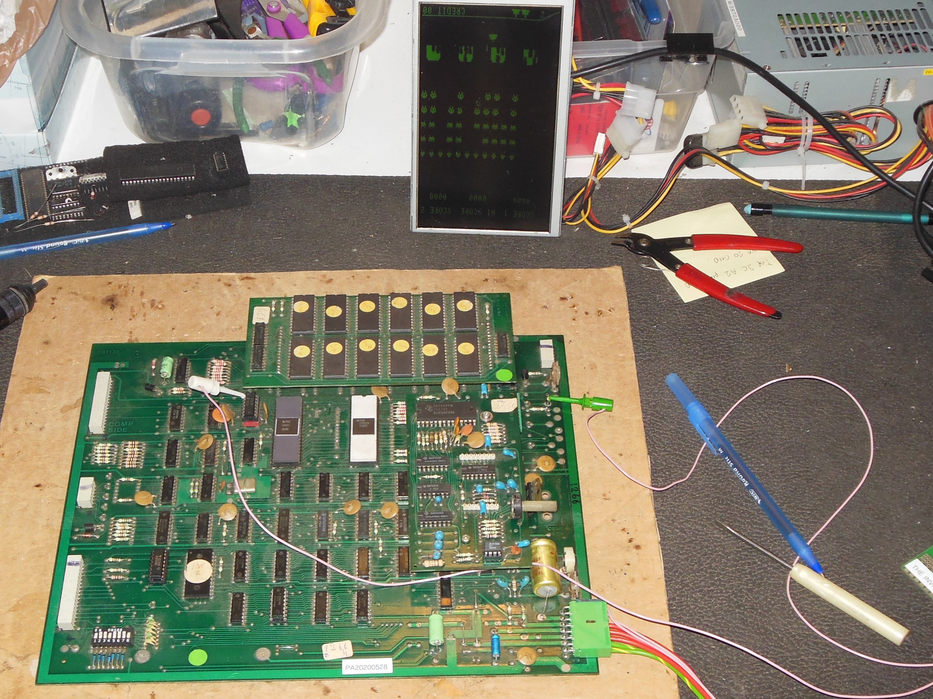
The game almost made it all the way to the finish line. On show day 3 one half of the screen developed graphics corruption and a spare game PCB was swapped in for the remainder of the show.
|
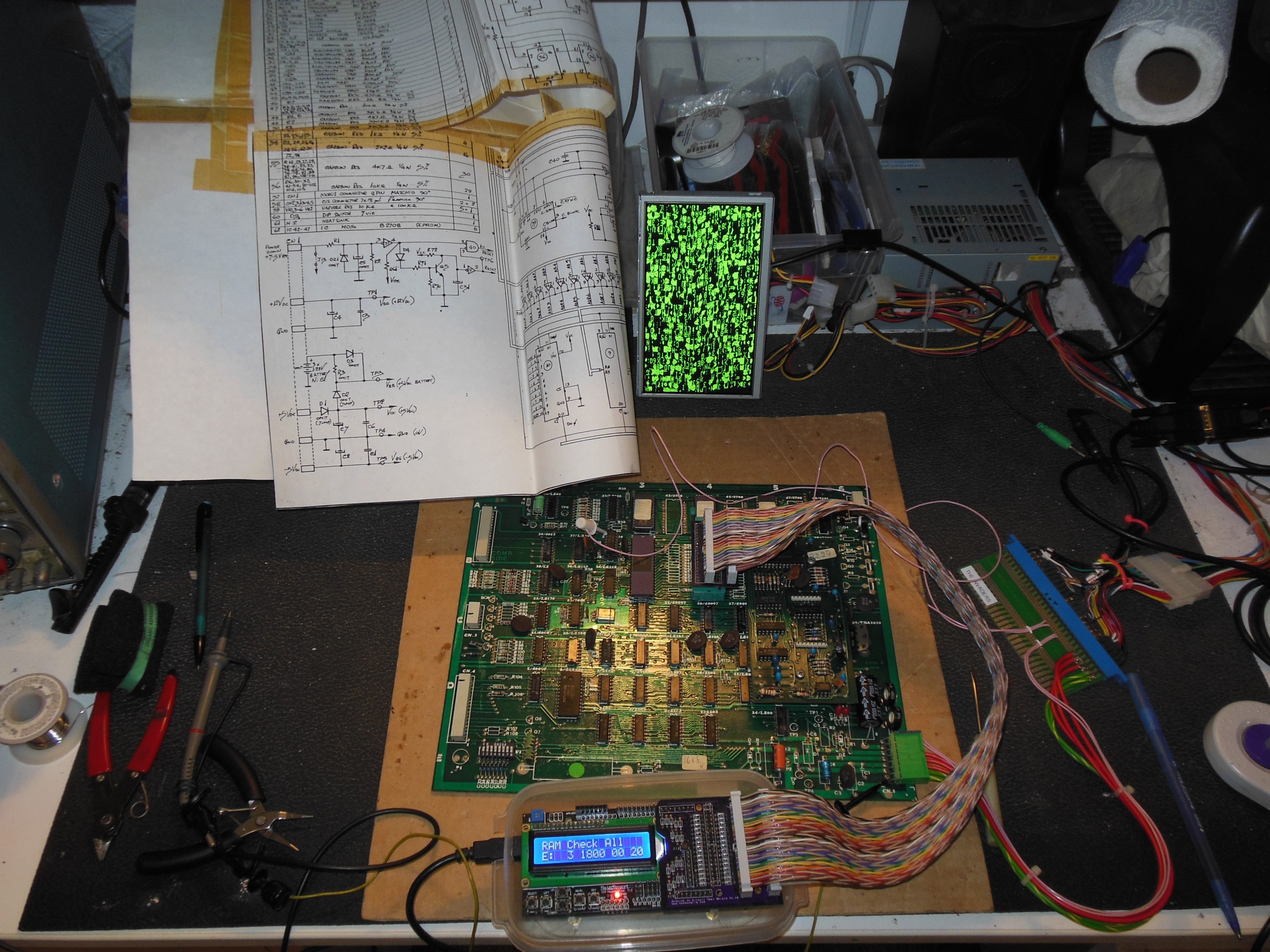
Half of the video display had incorrect characters selected. On the scope there were no obvious issues with the signals found on the eight 2102 video RAMs. Testing with the Arduino ICT the ROM tested OK, but one RAM test failed "E: 3 1800 00 20". Using "RAM Write All Hi" and "RAM Write All Lo" caused all the RAM data outputs to become idle high and idle low respectively except IC 3 that still had active output in both cases. I suspected IC 3 (2102) was bad and replacing it fixed the game.
|
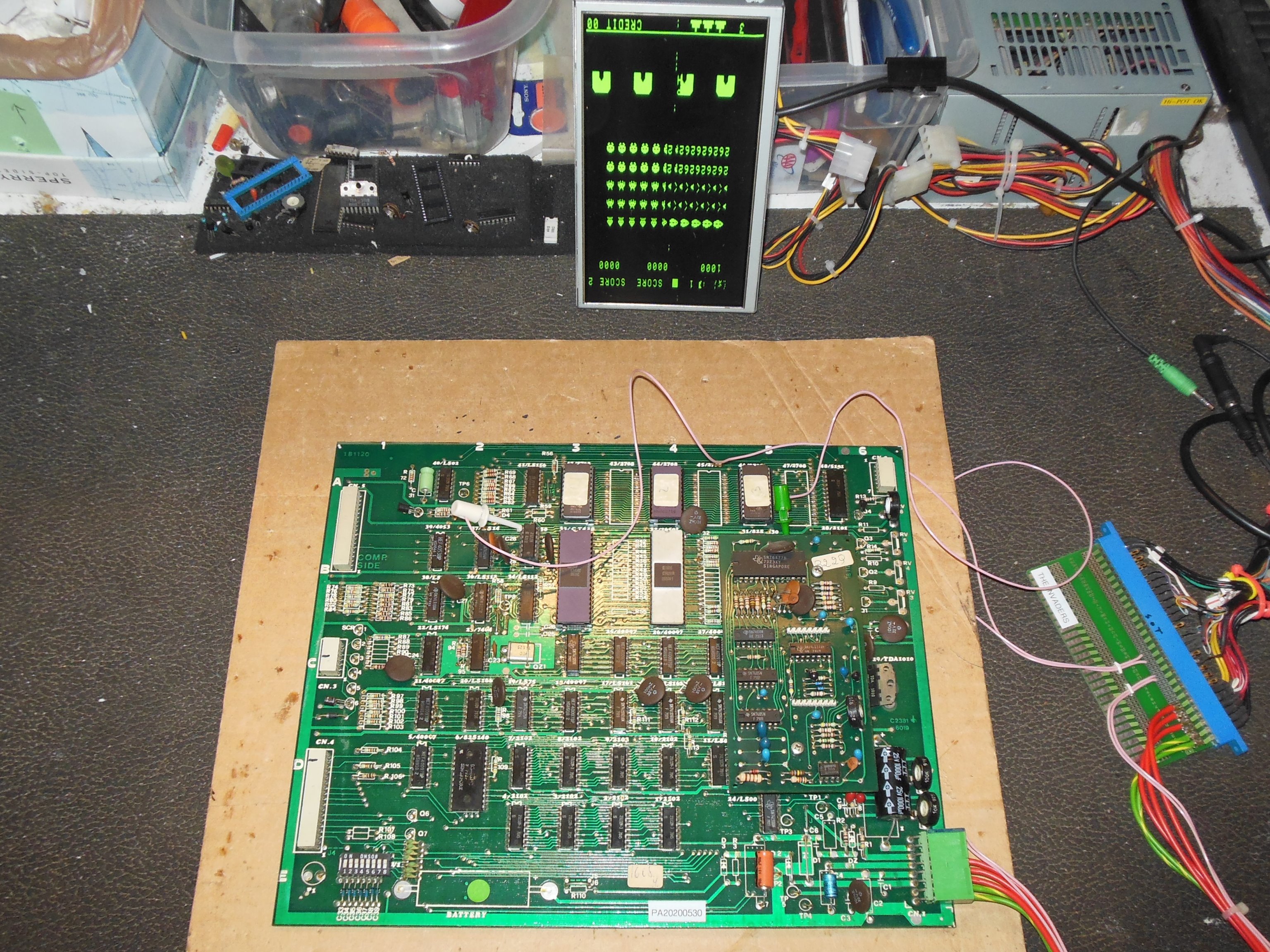
It had been quite a while since I'd had The Invaders on the bench, so I took the opportunity to capture the video signal taps for my JAMMA adaptor for reference. The Invaders native video output is composite, so the taps provide separate sync and video drive instead.
|
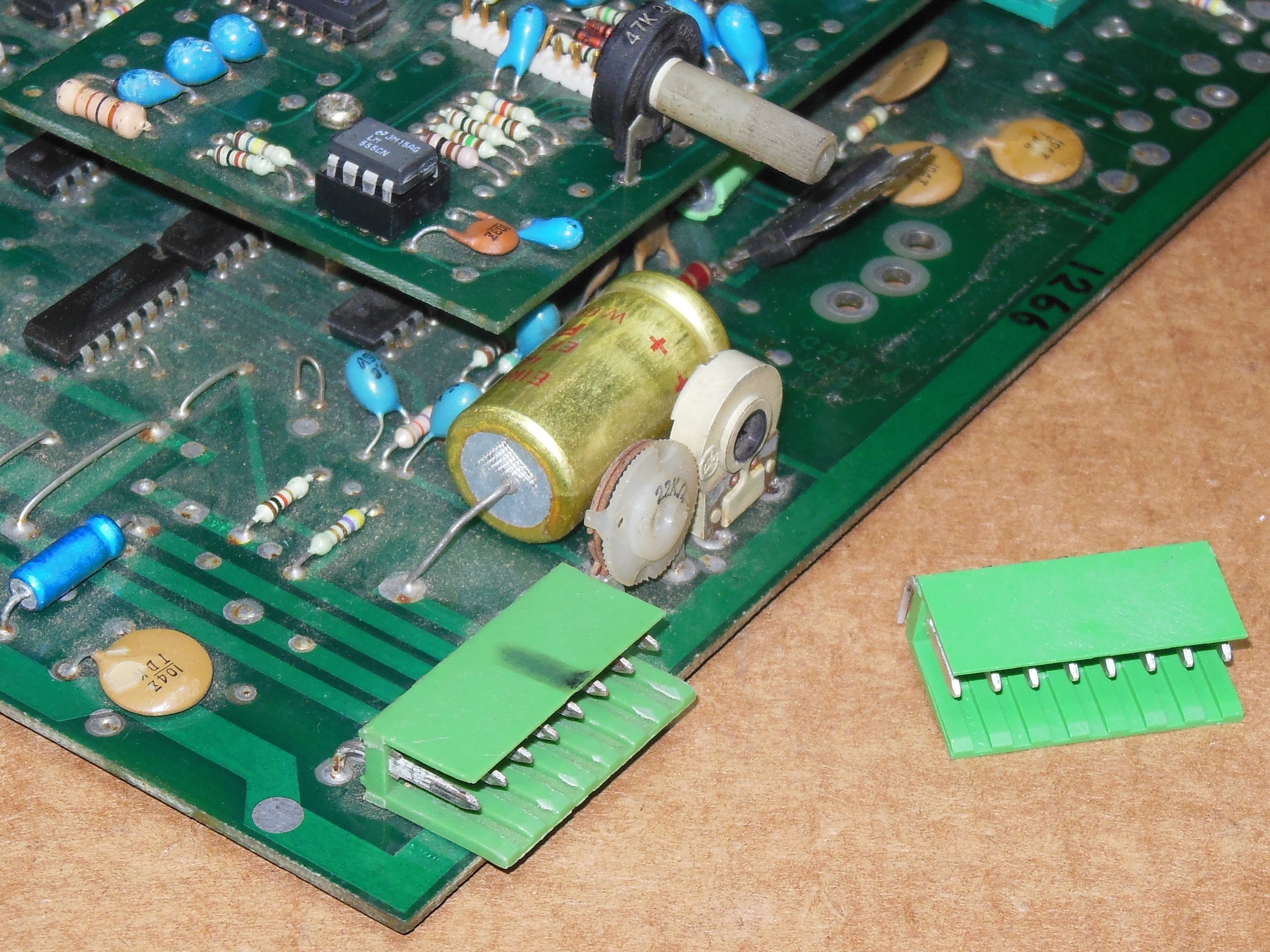
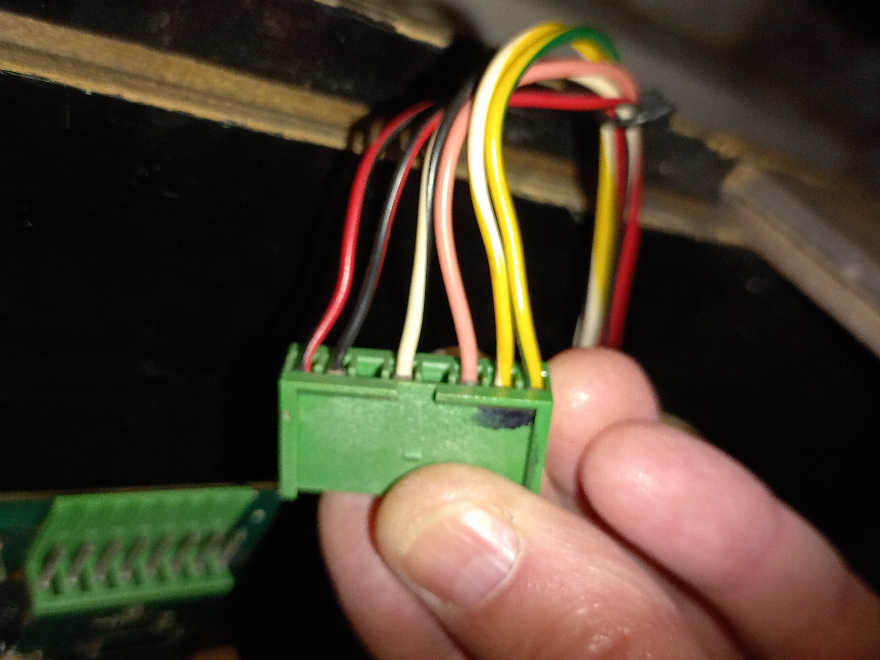
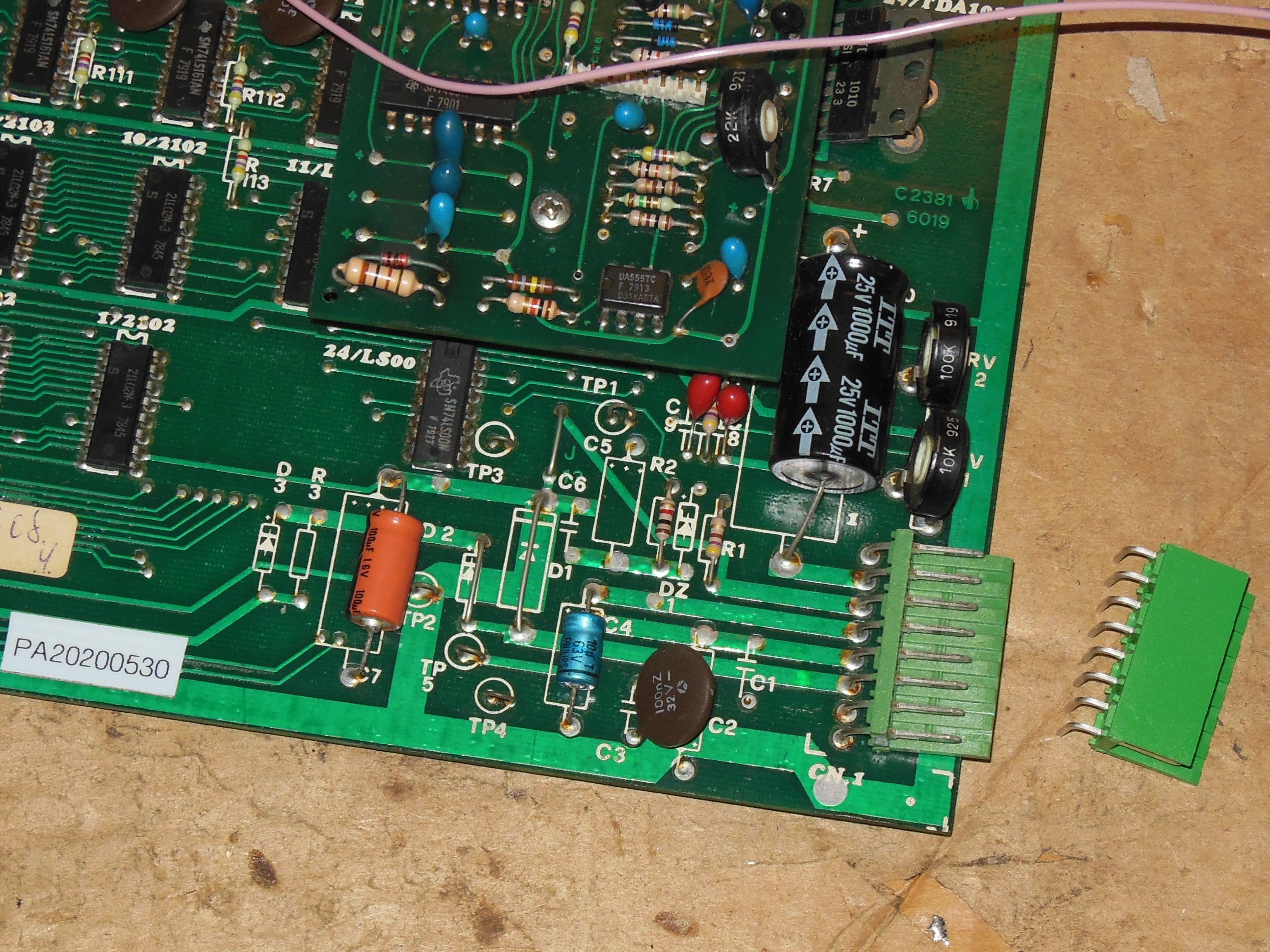
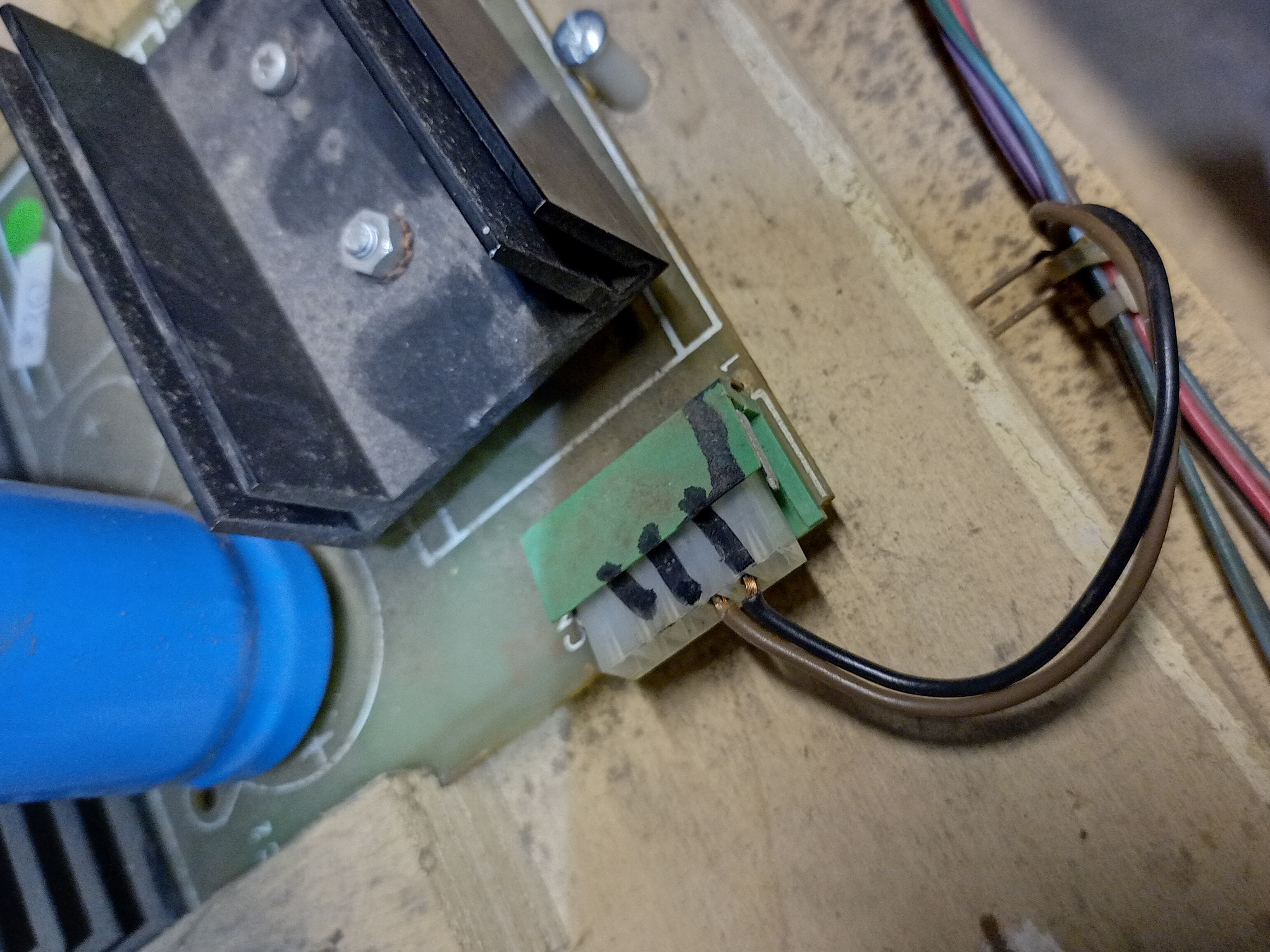
The power plug on this PCB was broken, causing an intermittent voltage drop, and replaced with a new one.
|
Visual inspection found that the poor connection with the game PCB was due in part to opened contacts in the power socket pins. The pins were removed and contacts closed.
|
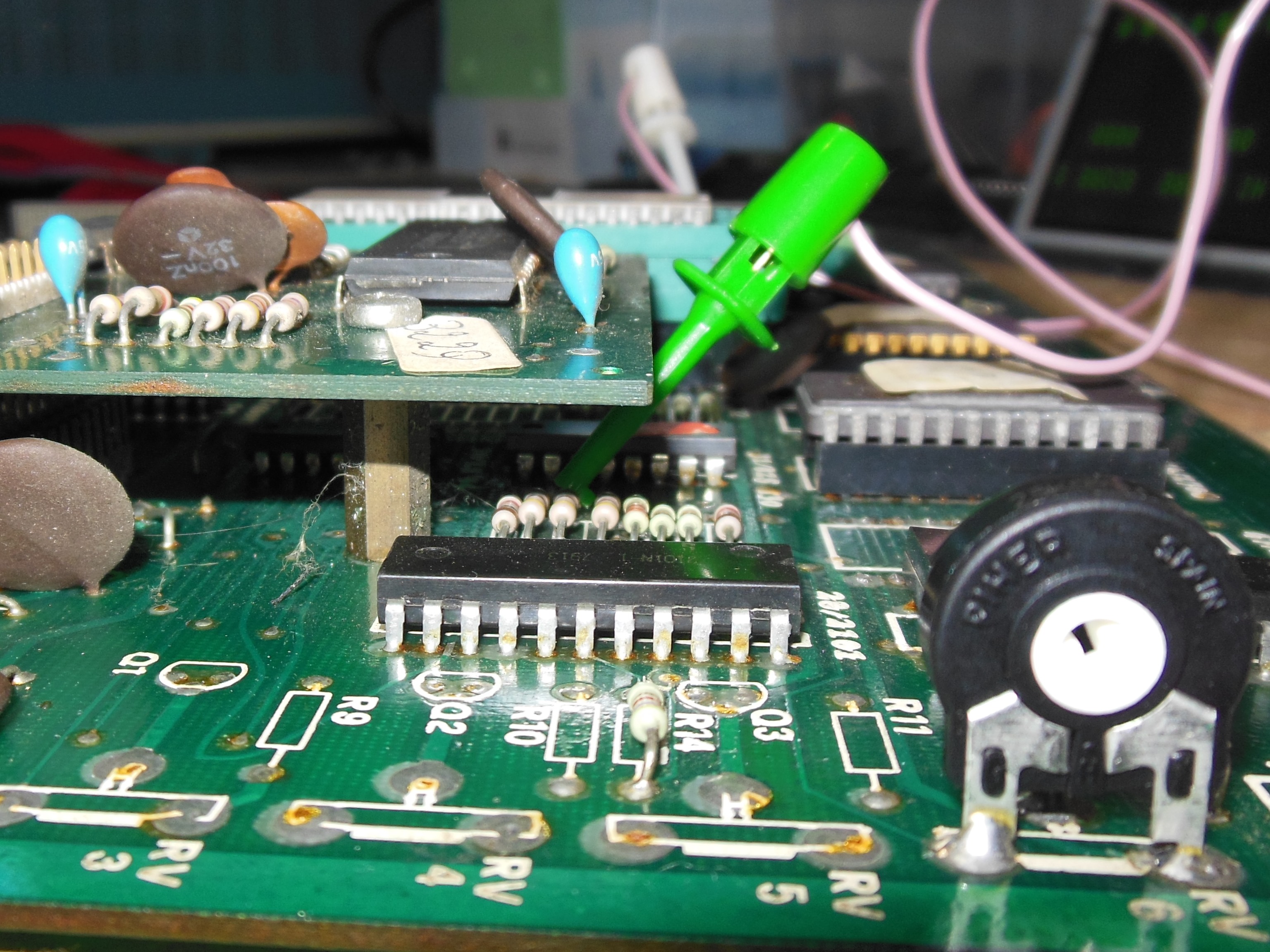
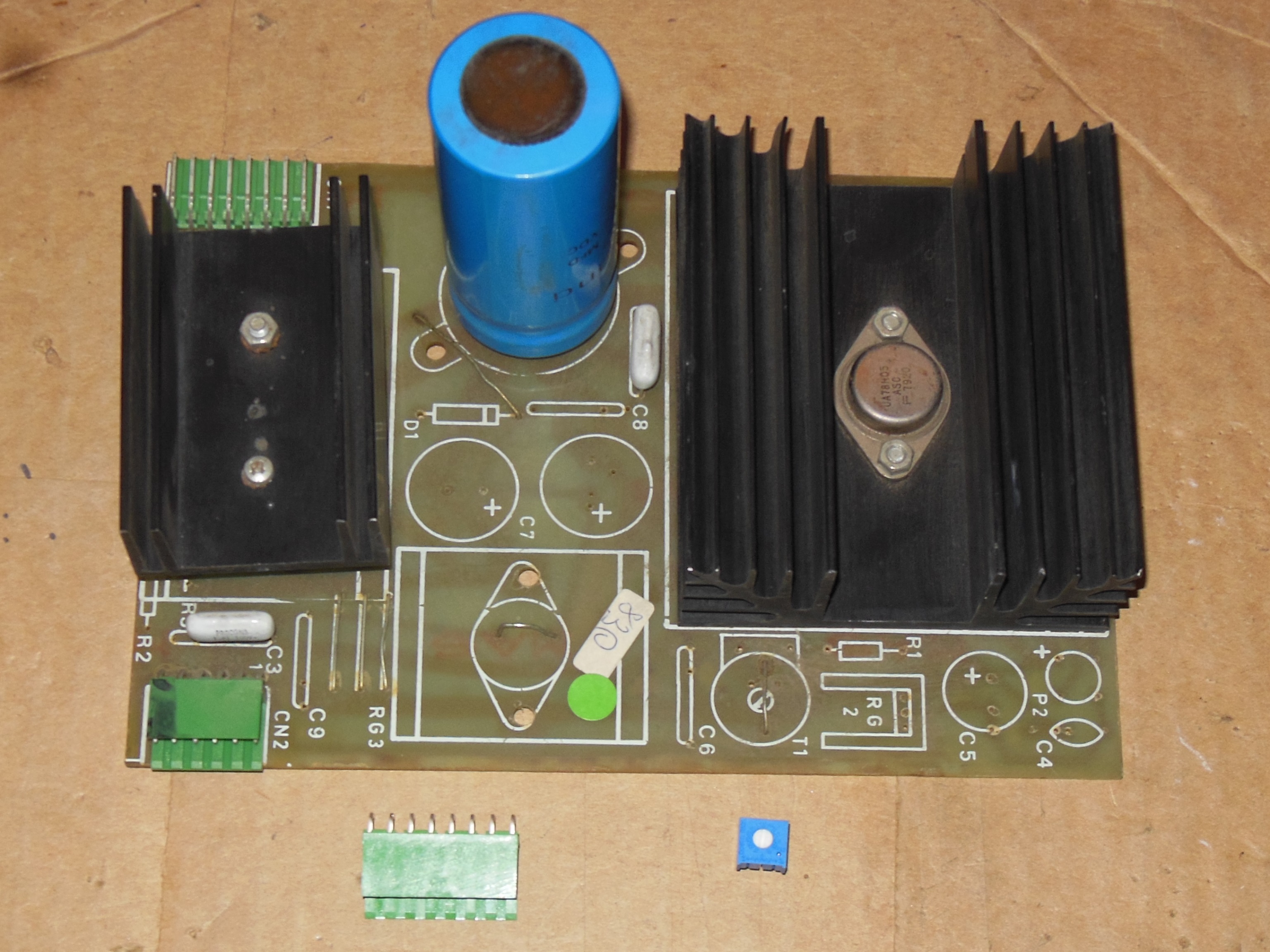
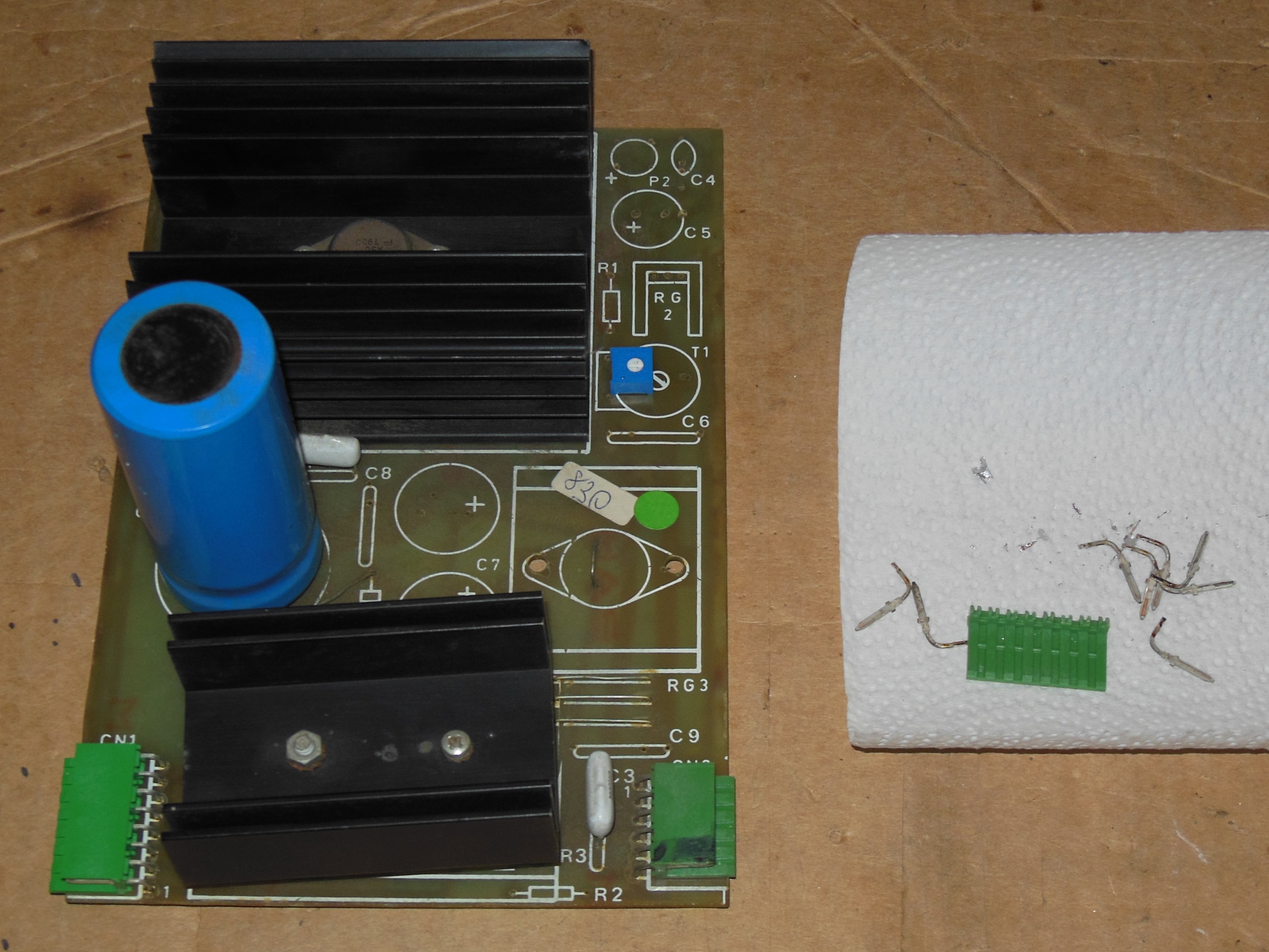
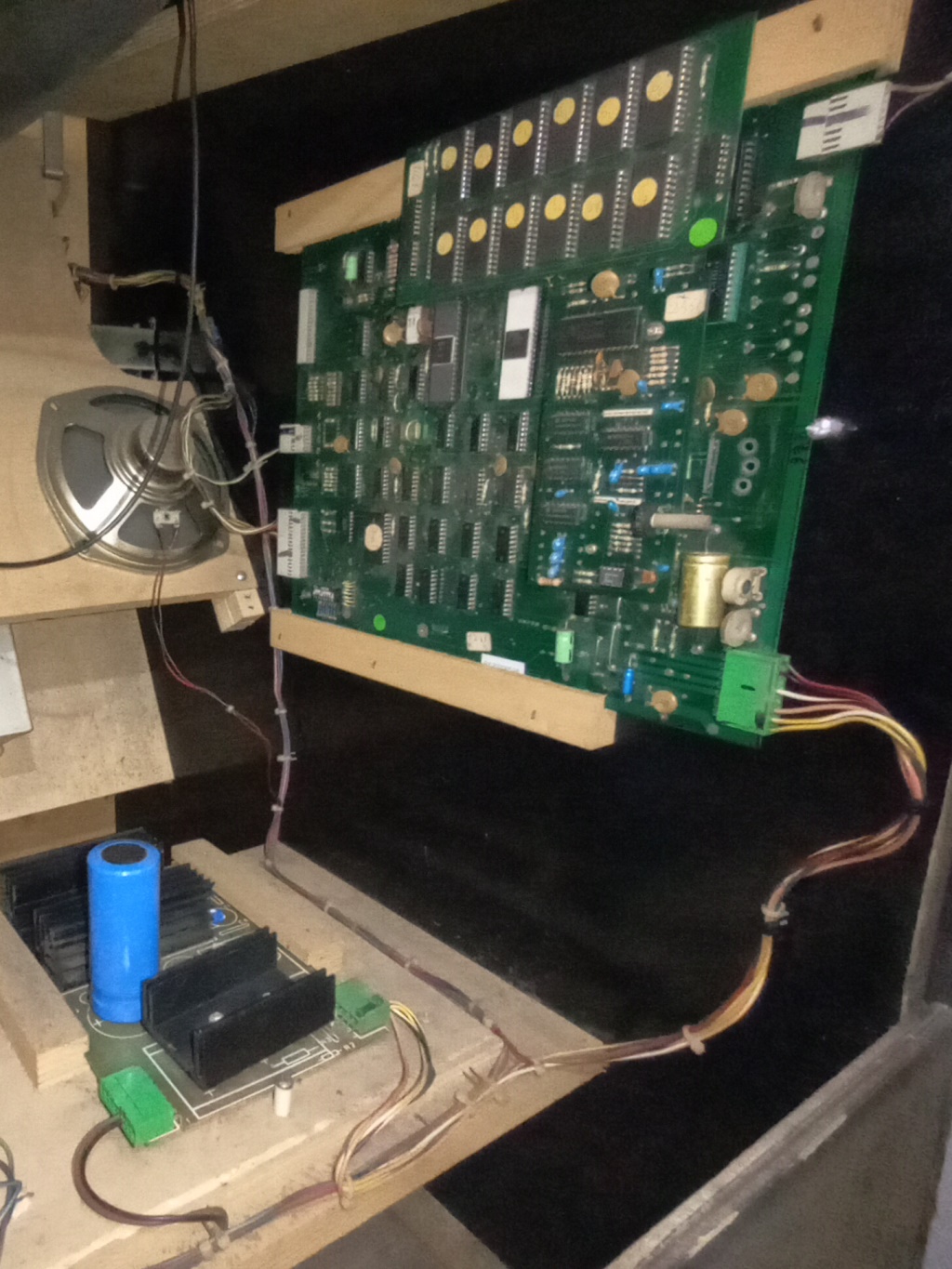
I'd also found power voltage variation as a result of pressing on the regulator PCB power plug. The PCB was removed and the power plug replaced. To allow for calibrating the +5V supply voltage, the +5V adjustment pot option was also fitted.
|
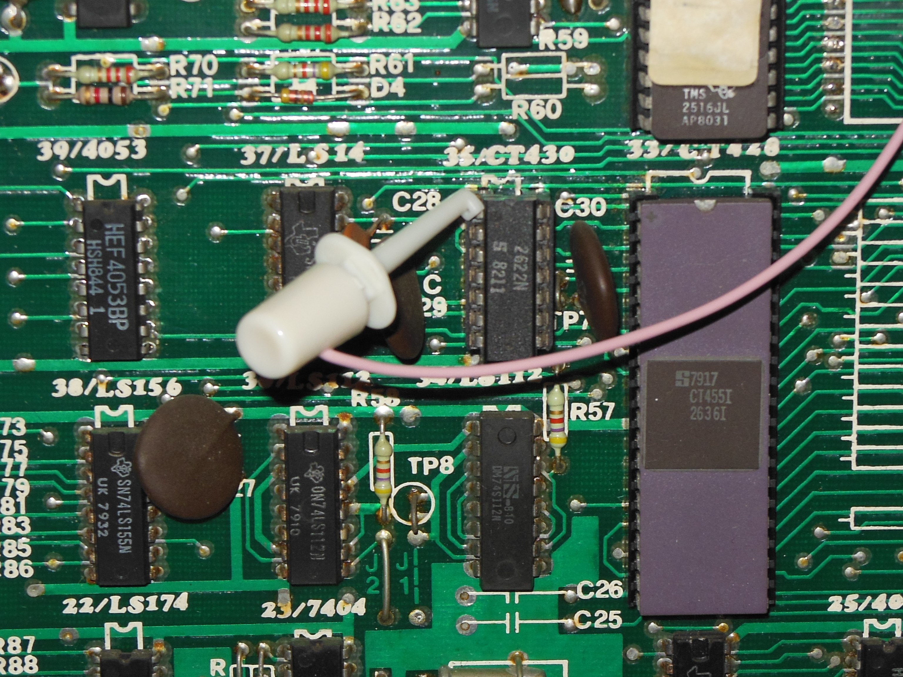
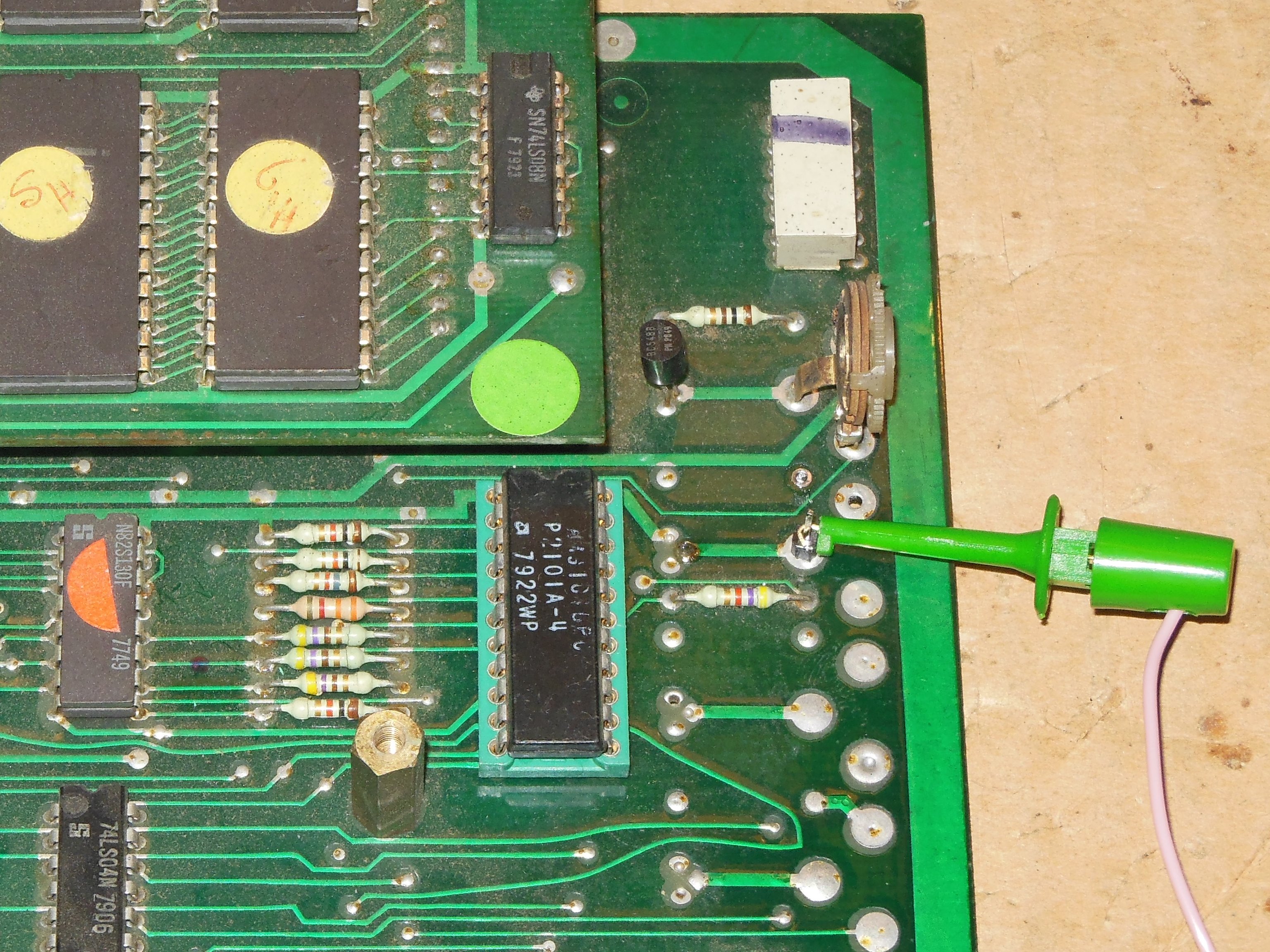
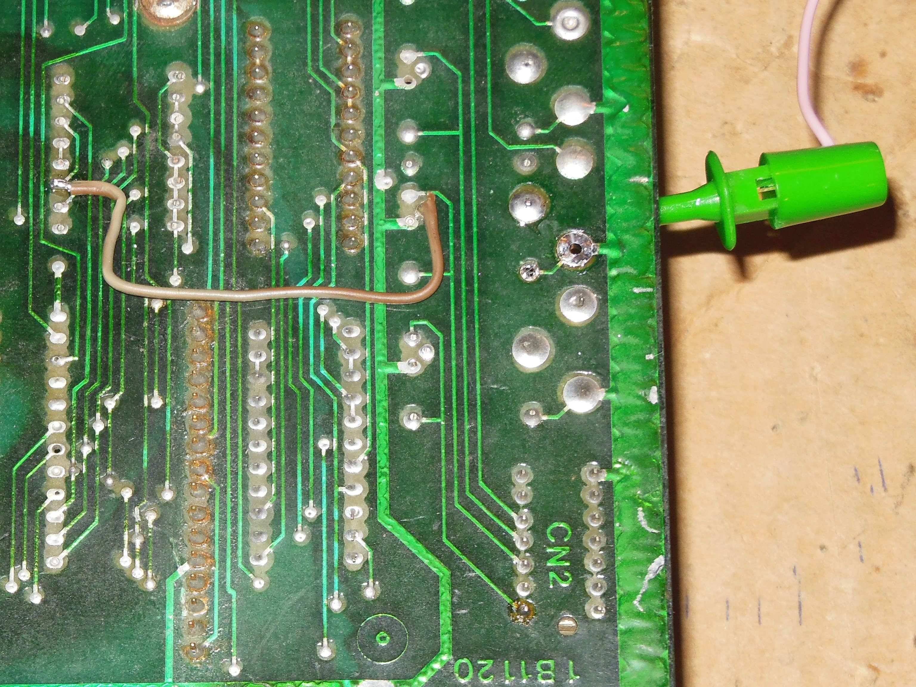
Composite sync was available directly from the 2621 pin 2 however the video output signal was tapped from the "colour" PROM output located underneath the sound PCB. To make the PCB easier to connect to without the need to remove the audio board, a wire strap was used to connect to a spare header pin. The modification was done on both game PCBs.
|
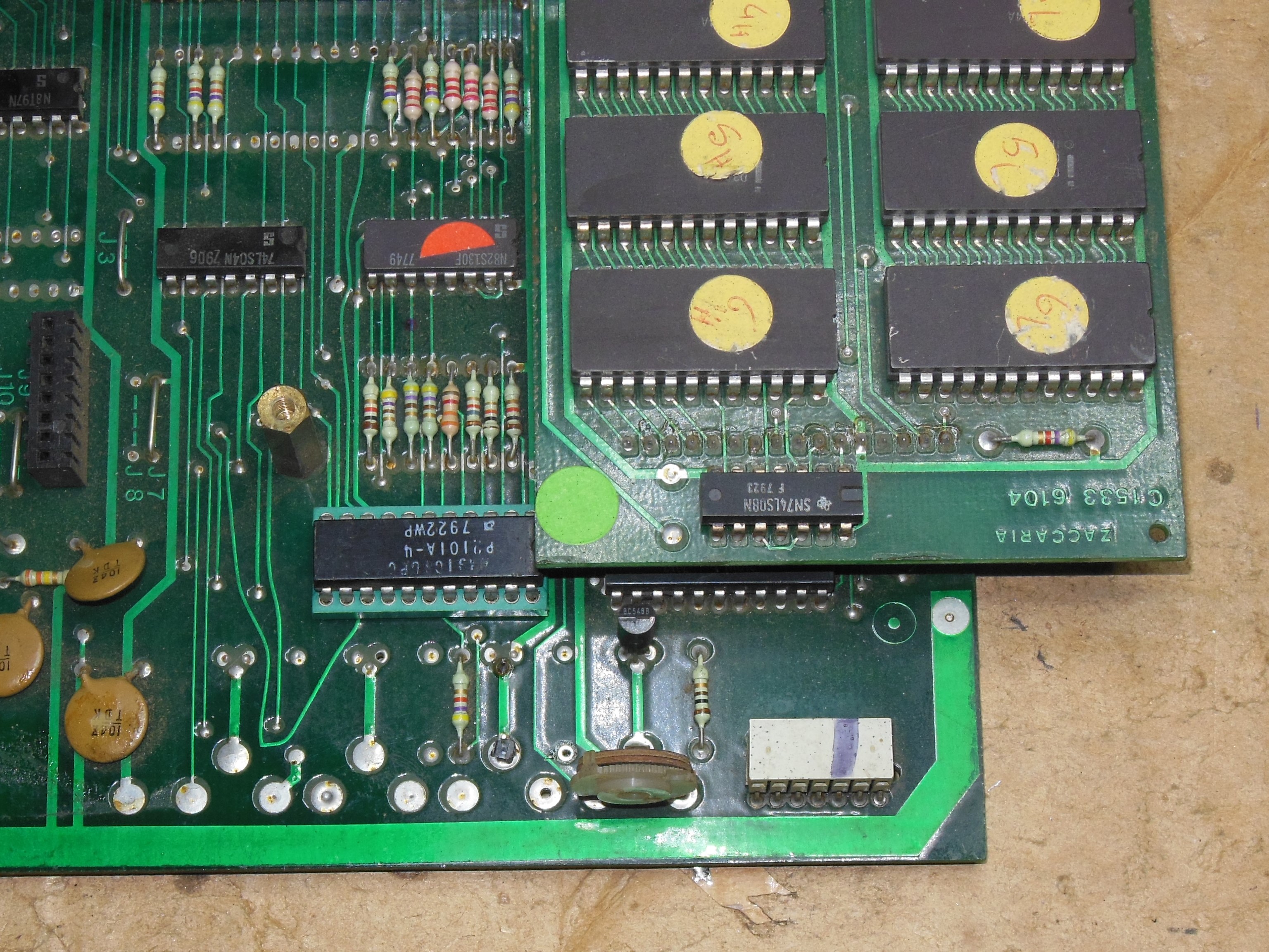
During pre-show testing the game PCB was no longer booting. Testing on the bench with the Arduino ICT found a "RAM Check All" failure "E: 48 1C00 01 0f" and all other ROM & RAM checks passing OK. Replacing RAM 48 (2101), awkwardly located under the ROM daughter PCB, fixed the RAM test and the game ran OK on the bench.
|
The power plug on this PCB was broken causing an intermittent voltage drop. It was replaced with a new one.
|
A previous "repair" had been done on the 1B1126 regulation PCB AC input socket that had used the wrong connector. That connector was replaced with the correct one and the game PCB was fitted and tested OK with a good stable power voltage.
|
Pre-show testing of this spare PCB found that it intermittently didn't boot or booted but then crashed. Testing with the Arduino ICT found ROM, RAM and interrupts working OK. Video output also seemed intermittent. Checking the 2621 sync generator found output pin 1 (~C.SYNC) had a ~0.7v high. Replacing it didn't fix the low output voltage. Tracing forwards, the signal was an input to IC 31 pin 14 (82S130), the "colour" PROM. Checking other outputs of the 2621 sync generator found pin 6 was also impacted by clamping. Carefully removing IC 31 to preserve it (it was very diificult to replace) allowed the 2621 outputs to be full swing. The act of removing IC 31 appeared to have improved the clamping - it was still around ~2V high and was unstable but hovered high enough to not impact video anymore. Since the PCB was working reliably again it was left as is with an ongoing investigation to locate a replacement IC 31 PROM.