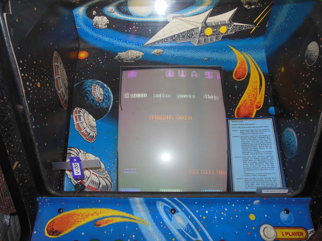
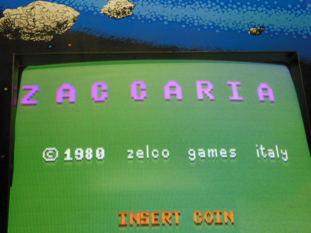
I bought this whilst I was living in California in the early 2000's. The cabinet is in excellent condition inside and out and is all original. Since it was in such good condition no significant restoration is needed. It was also working fine however the monitor had started to deteriorate - it used to take ten minutes or so to stabilize from rolling but by May 2014 it had also developed tearing and the game board had become unstable, crashing and failing to boot. Therefore it was time for some repair work.
|
|
|
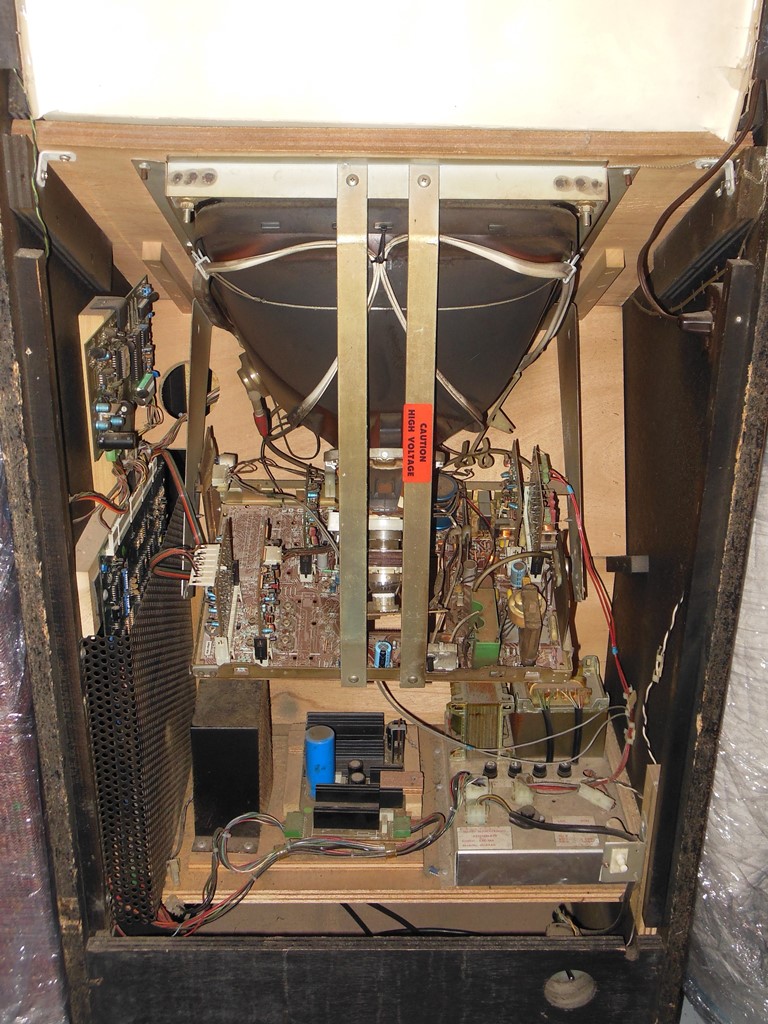
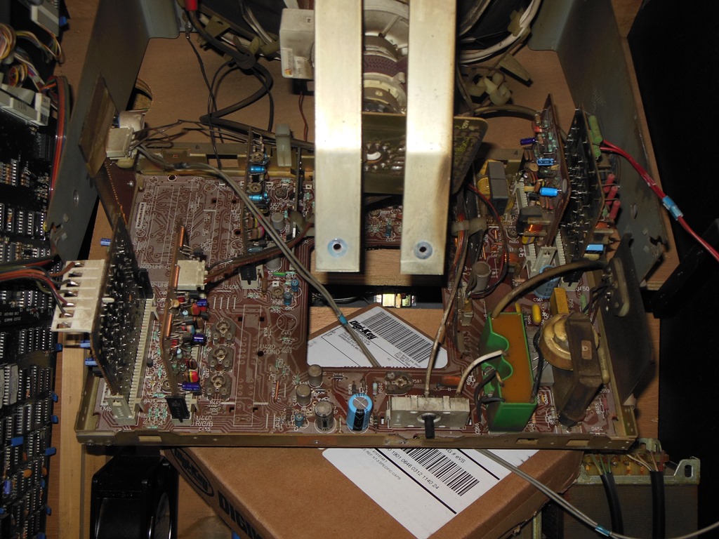
Internally, the electronics are nearly identical to the native Zaccaria Quasar - using the same power supply & Philips KT-3 monitor with an extra step down transformer bolted next to the original transformer. The artwork is completely different from the native Zaccaria artwork.

|
Power yielded similar results to prior testing - jittery unstable picture and sometimes it would boot and sometimes not. The power supplies looked OK and I suspected monitor & board problems.
|
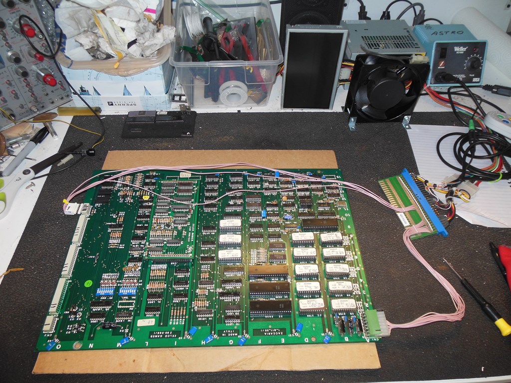
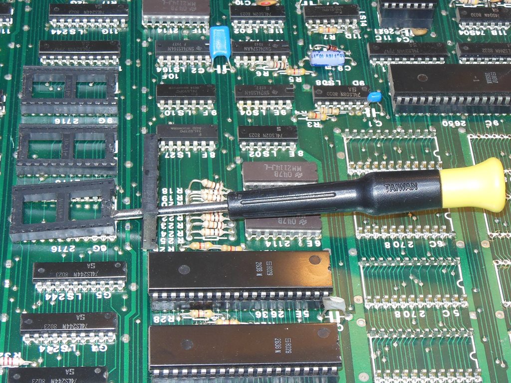
Setting up the board on the bench for testing (replacing the PAL 2621 with an NTSC 2622 to get the board to sync on the LCD monitor) confirmed that there was a board issue. Pressing on the program ROMS caused the game to crash & not boot so at least the ROM sockets were looking bad. Cleaning all the pins on the ROMS and reseating them resulted in the board no longer booting at all :( Checking with a meter revealed multiple open socket pins. The board needed at least all 13 of ROM sockets replacing :( I decided to order a vacuum de-solder tool for this since there was a lot to replace.
|
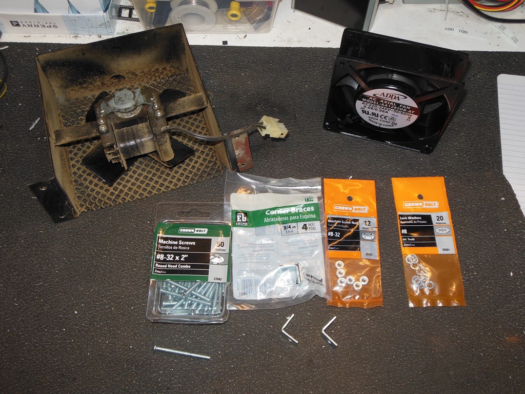
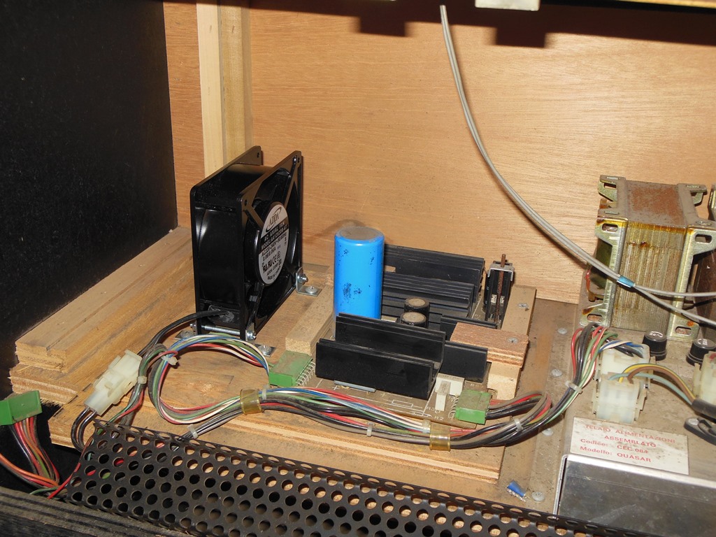
The fan was no longer working properly as is nearly always the case now. A new fan (a 220V ADDA AA1282DB-AT) along with some L brackets created a suitable equivalent replacement for the cabinet.
|
|
There are also a number of capacitors on the chassis itself in addition to the ones on the daughter cards but since I was having sync related problems I decided to first start with the capacitors on the daughter boards that can be serviced without removing the entire chassis from the cabinet.
The chassis is based on the Philips KT-3 TV chassis
used in a number of European TV models in the late 70's to early 80's. The monitor version
of the chassis is for the most part the TV chassis with the front end tuner & audio
panels & components omited and a RGB video input panel substituted in place of the
luminance/chrominance panel. The full service manual for the TV chassis and related
TV models is extensive and detailed but it doesn't cover the monitor version of
the chassis explictly.
There are two scan packages available -
the full set of everything as scanned and an abridged set of more compressed content
relevant only to the monitor implementation:
Philips KT-3 Chassis Service Information, abridged. (48.4MB).
Philips KT-3 Chassis Service Information, full set. (197MB).
The latter also covers the Pye 7228, 7324, 7225, 7227, 3150 & 7323 TV sets.
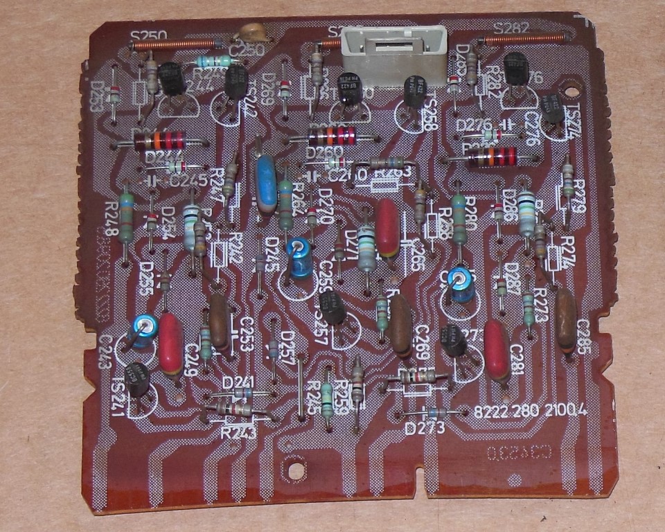
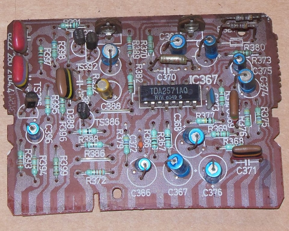
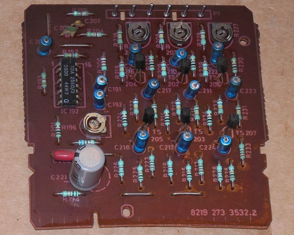
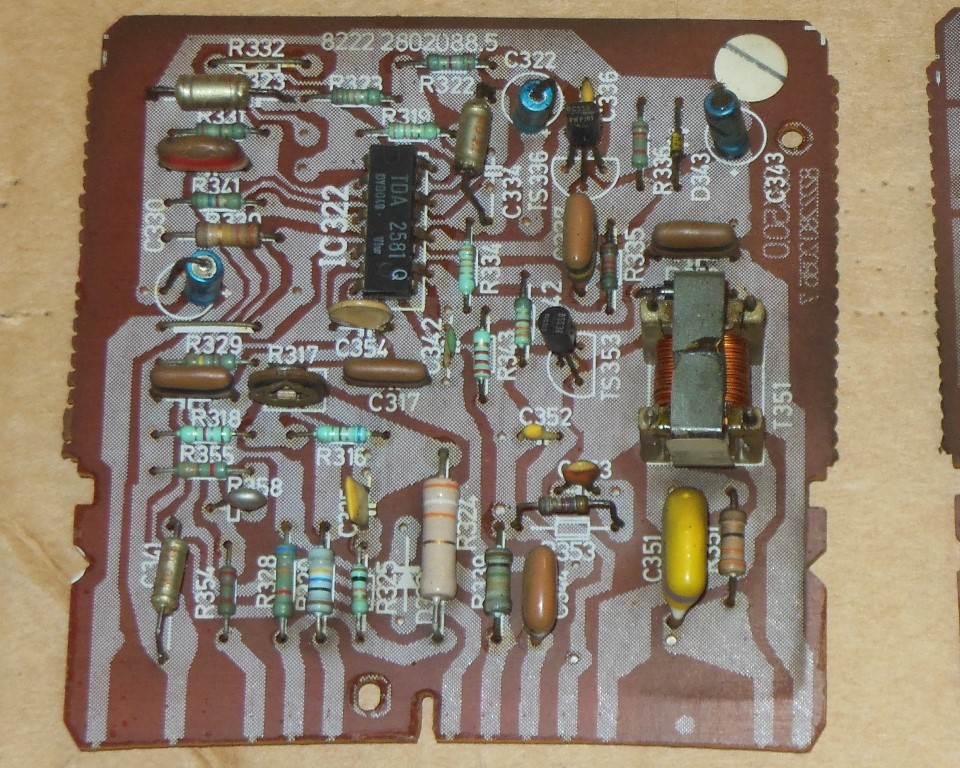
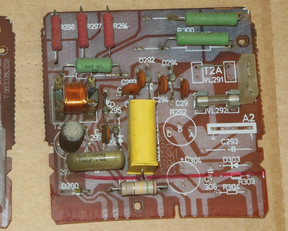
The daughter boards contain the following capacitors (note that to cross reference with the above manual the PCB location designation has a single digit prefix added to it that indicates the panel number it applies to, e.g. C243 is C4243 in the parts list):
| 8222-280-2100.4 R-G-B OUT-PUT '4' |
8222-280-2104.4 LINE-FRAME-SYNC '8' |
8219-273-3532.2 video input '3' |
8222-280-2088.5 SUPPLY CONTROL '7' |
8222-280-2246.2 a/c input '6' |
|||||
|---|---|---|---|---|---|---|---|---|---|
| Location | Original | Location | Original | Location | Original | Location | Original | Location | Original |
| C243 | 22uF 25V |
C366 | 4.7uF 63V |
C191 | 4.7uF 63V |
C322 | 1.0uF 63V |
C300 | 470uF 16V |
| C259 | 22uF 25V |
C367 | 47uF 25V |
C192 | 6.8uF 63V |
C330 | 4.7uF 63V |
C304* | 470uF 25V |
| C275 | 22uF 25V |
C368 | 10uF 63V |
C204 | 10uF 25V |
C343 | 47uF 10V |
. | . |
| . | . | C374 | 10uF 63V |
C210 | 10uF 25V |
. | . | . | . |
| . | . | C375 | 2.2uF 63V |
C211 | 10uF 25V |
. | . | . | . |
| . | . | C376 | 10uF 63V |
C212 | 10uF 25V |
. | . | . | . |
| . | . | C377 | 1.0uF 63V |
C216 | 10uF 25V |
. | . | . | . |
| . | . | C380 | 47uF 25V |
C217 | 10uF 25V |
. | . | . | . |
| . | . | C386 | 47uF 25V |
C218 | 10uF 25V |
. | . | . | . |
| . | . | C396 | 2.2uF 63V |
C221 | 1000uF 16V |
. | . | . | . |
| . | . | . | . | C222 | 10uF 25V |
. | . | . | . |
| . | . | . | . | C223 | 10uF 25V |
. | . | . | . |
| . | . | . | . | C224 | 10uF 25V |
. | . | . | . |


|
The desolder tool arrived and I removed all of the old EPROM sockets with it. The sockets were of a type that can be removed by levering up the body and then removing the pins one by one. The new desolder tool worked fine for this and was only $80 off Ebay.
|
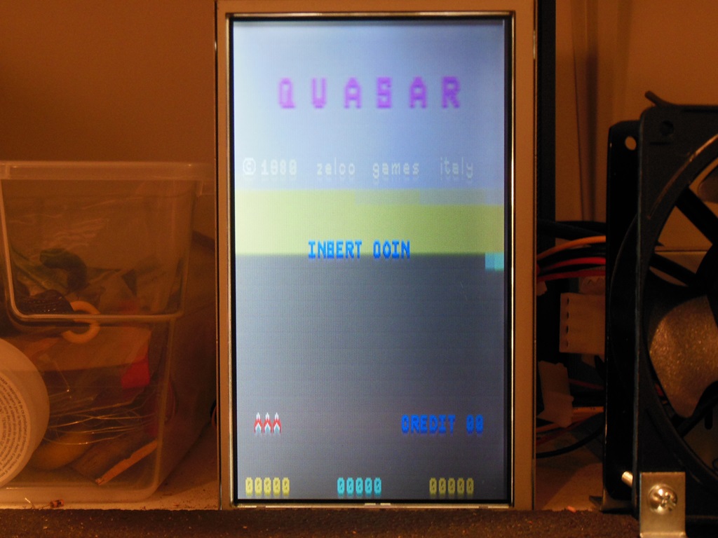
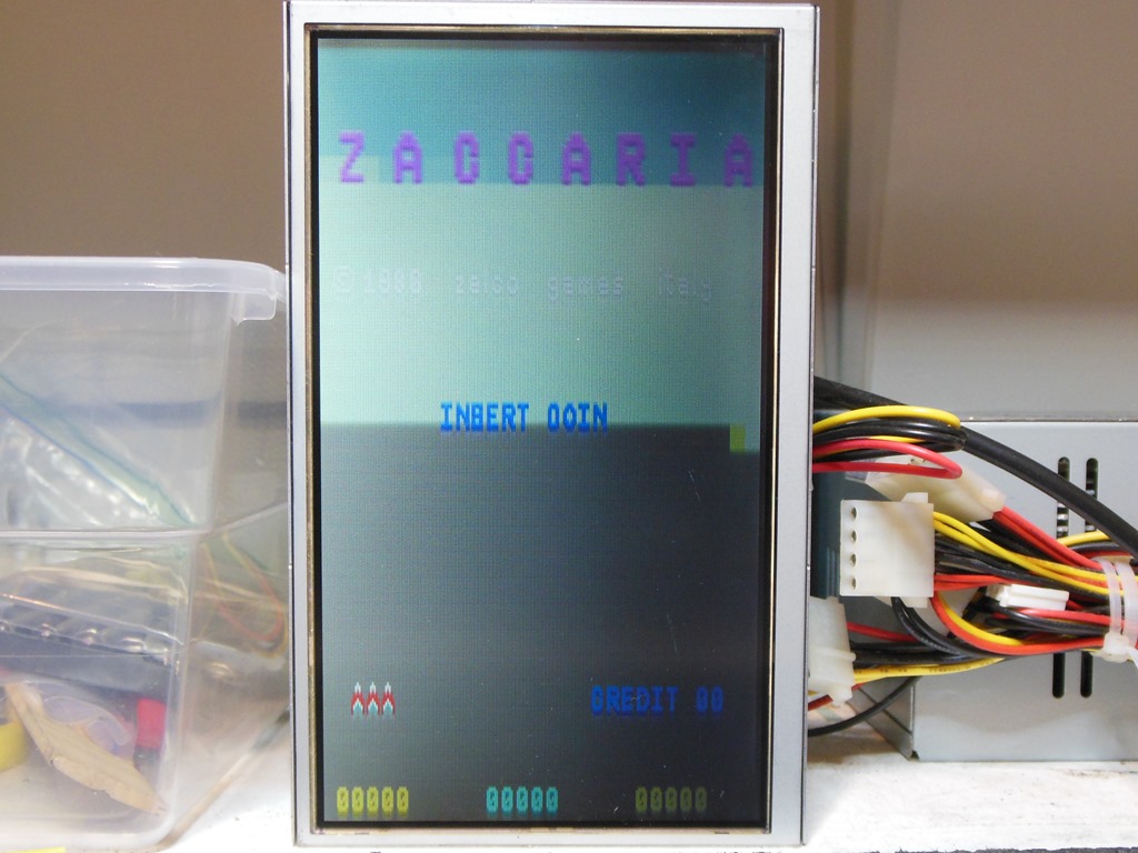
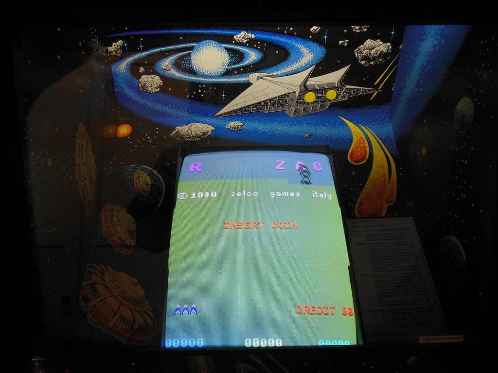
With all the old sockets replaced and the EPROMS reinstalled the game ran fine with no signs of any further reliability issues (the graphics artifacts on the bench are due to the 2622 sync IC used for testing). Back in the cabinet the game also ran fine. Attention turned to the geometry of the picture since it was too high and two big, however before adjusting the monitor the cardboard surround needed some work because it had drooped down too low to start with.
|
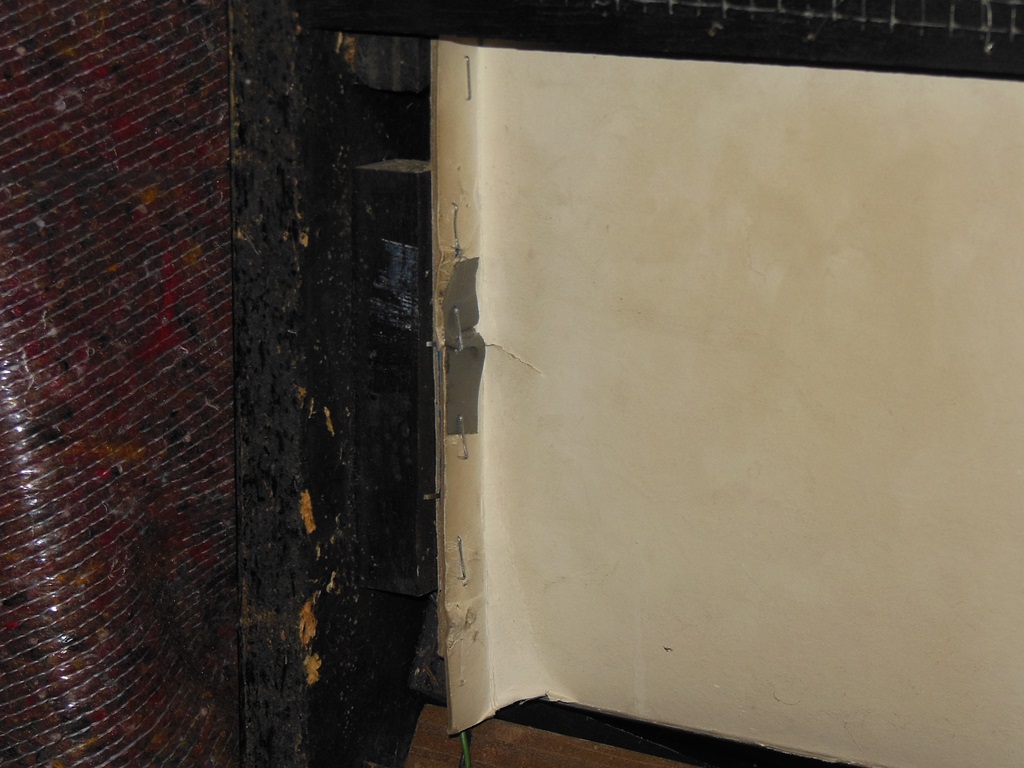
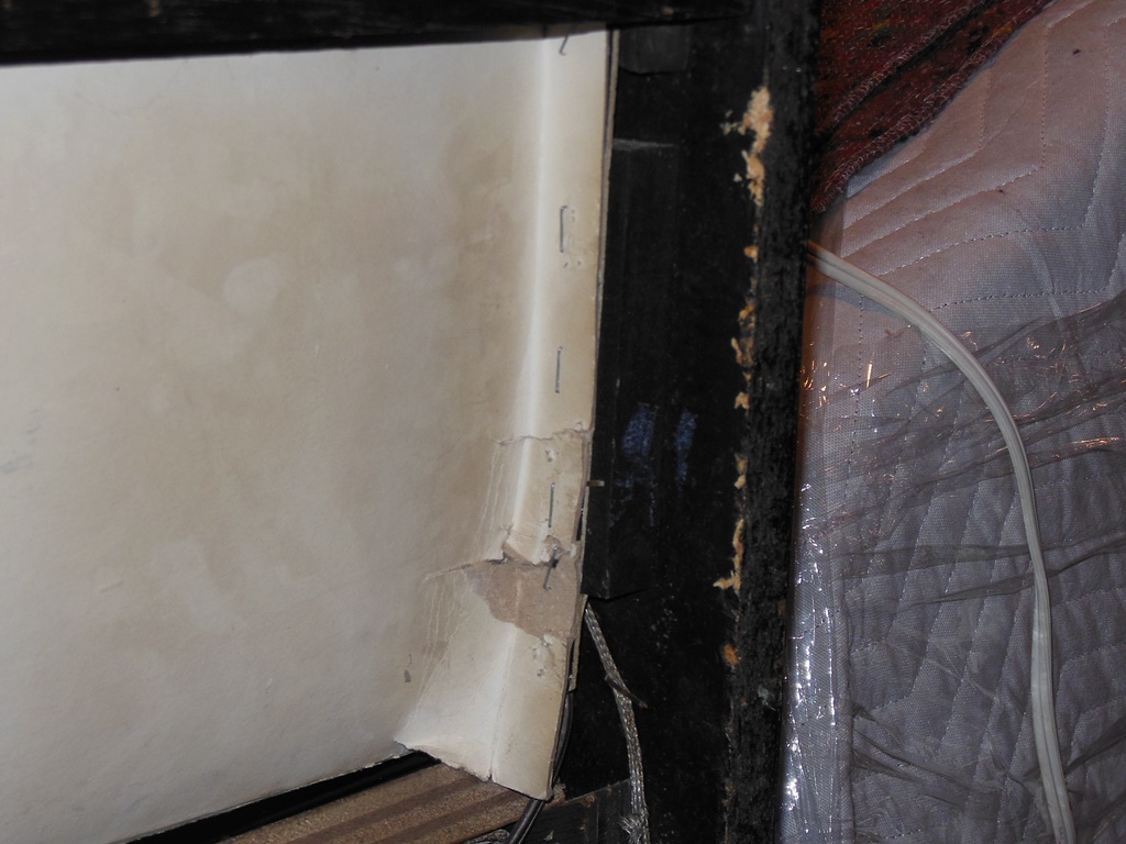
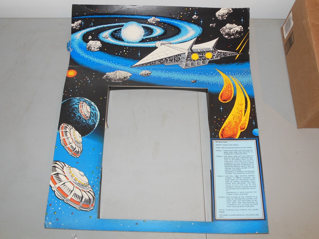
The monitor surround had some damage to the tabs from prior removal, bowing of the back panel and drooping around the monitor itself. The combination of all that caused it to sit too low on the CRT making the lower edge (and bottom portion of the game instructions) fall underneath the control panel. Removal was straight forward as the surround is only secured using staples in the back tabs (there are no staples in front like there are in the native Zaccaria surround).
|
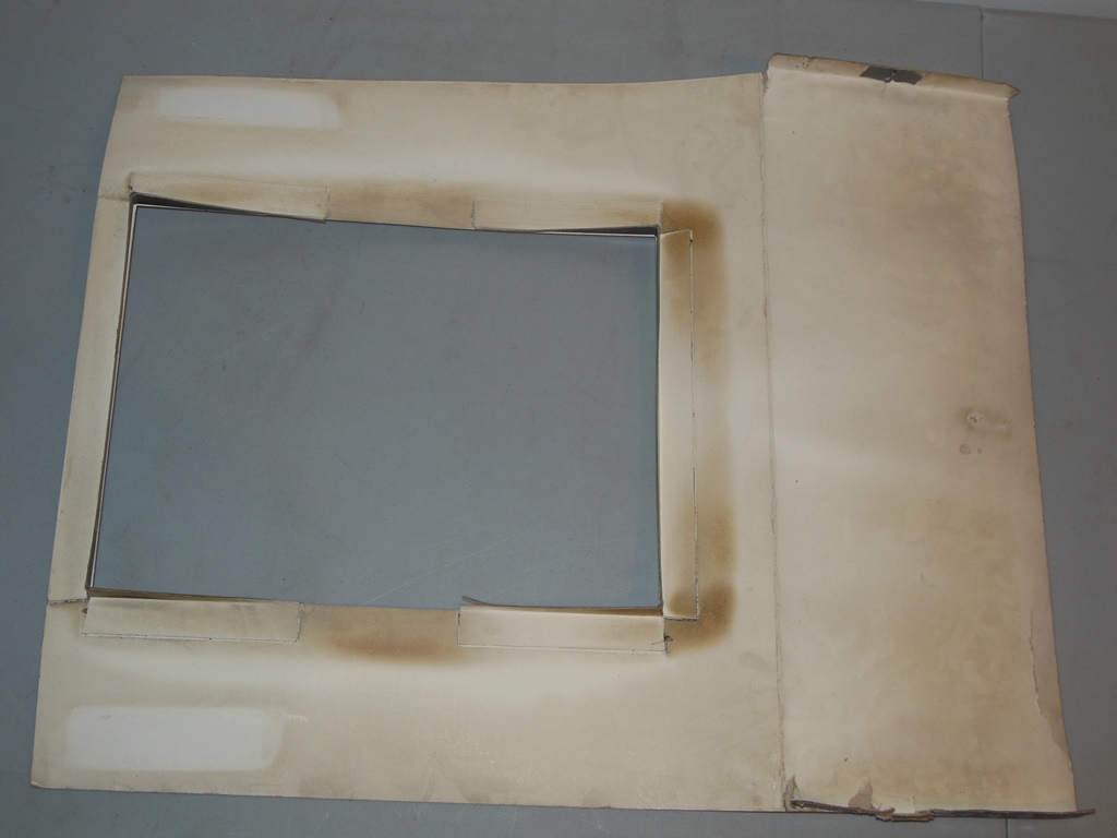
The surround wasn't all that dirty and only needed a wipe with a damp cloth.
|
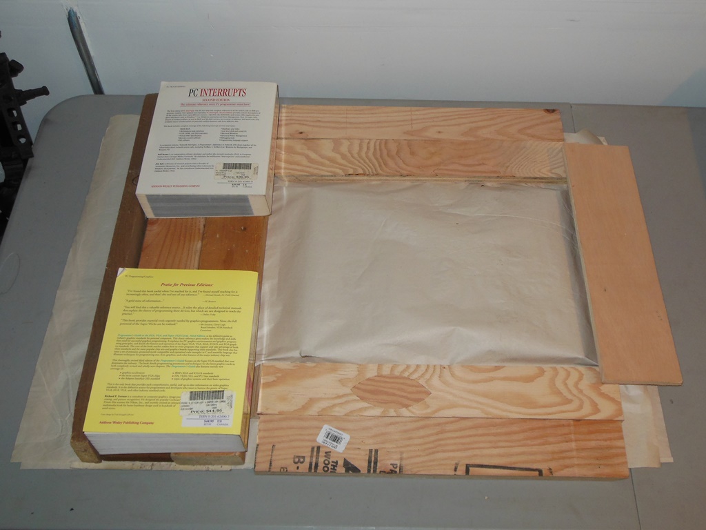
Since this surround has additional pieces around the monitor cutout to give a flush fitting around the CRT, the flattening out of the straight pieces was applied around the edges to avoid them.
|
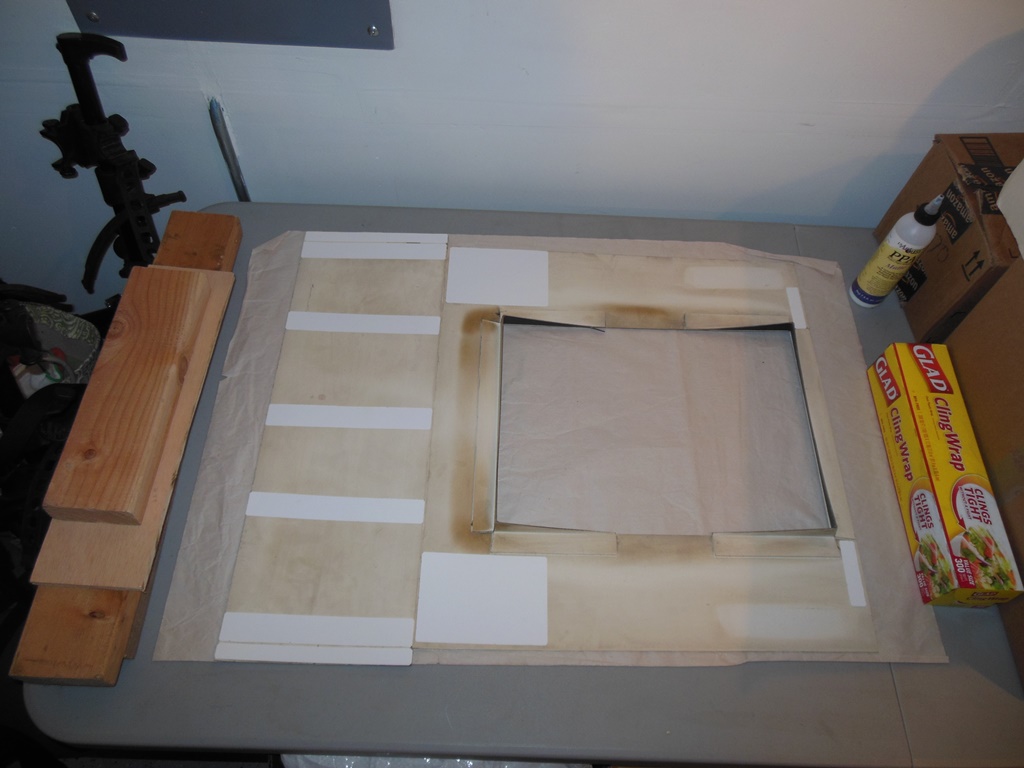
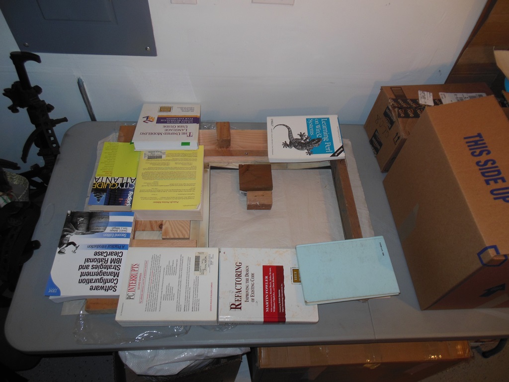
The surround needed some reinforcement ribs and patches to keep the back straight and the sides from sagging. These were cut, positioned and then glued in place followed by a few days of setting time.

|
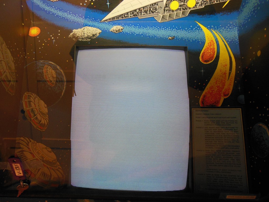
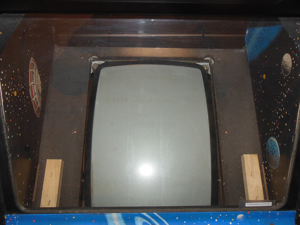
The surround was refitted back into the cabinet and secured with staples. As can be seen from the photos the removal of the curving & sagging allows it to set further up the CRT and the game instructions are now properly visible.
Attention turned to setting up the monitor geometry. There were still monitor problems since adjusting the geometry & linearity caused the sync to need adjustment. In fact, anything other than "full" linearity caused permanent loss of vertical sync :(


|
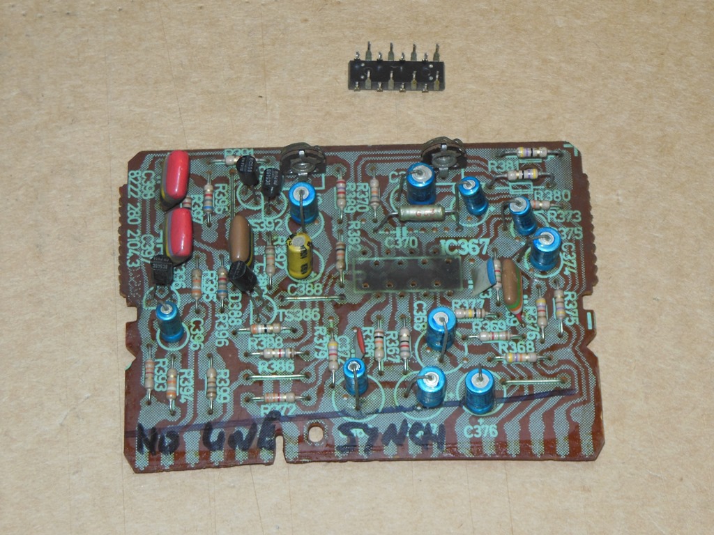
I have a bag of none-working spare daughter boards for the Philips KT-3. The first plan of attack was to repair a spare sync board and try it in the monitor to confirm if the problem was with the monitor chassis or the sync board. Since the sync board has just one IC and a few discrete components I did some basic verification of the transistors and concluded the TDA2571AQ was most likely bad. The "Q" in this name refers to the "zigzag" pin configuration, so I needed to zigzag a socket that would allow a replacement standard (none-Q) TDA2571A to be used in the standard DIL socket.
|
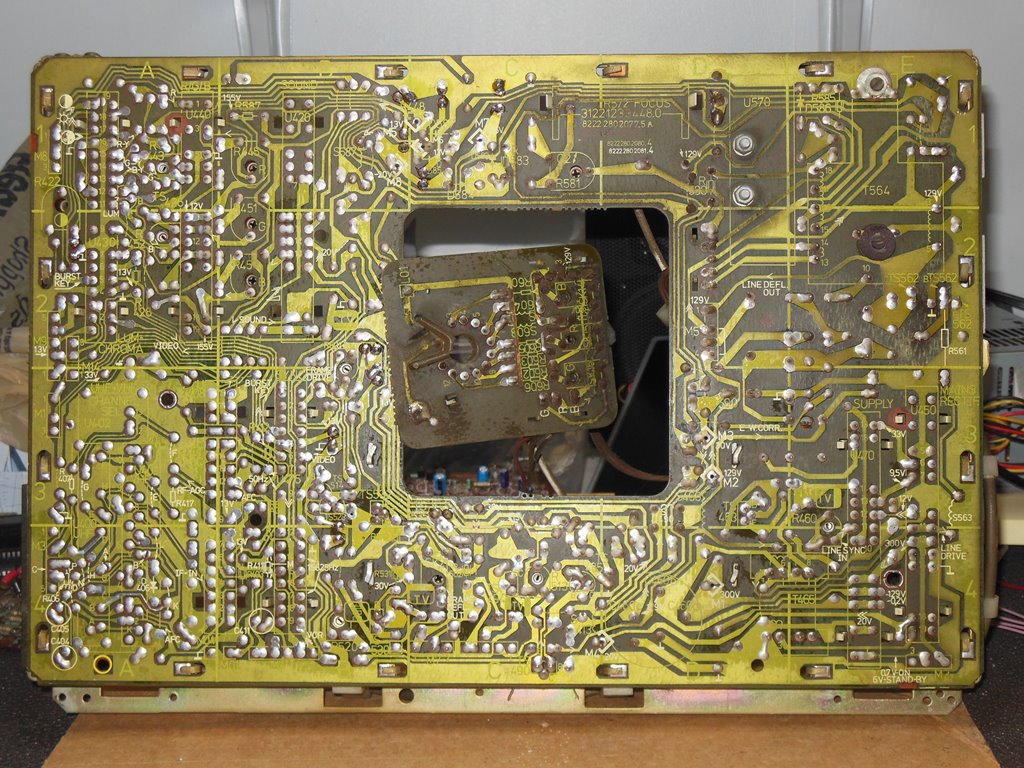
Both the original sync board and the newly repaired sync board behaved the same (poor sync lock and an odd picture artifact in the top right corner). Thus, the next step was to remove the main chassis and inspect it on the bench.
|
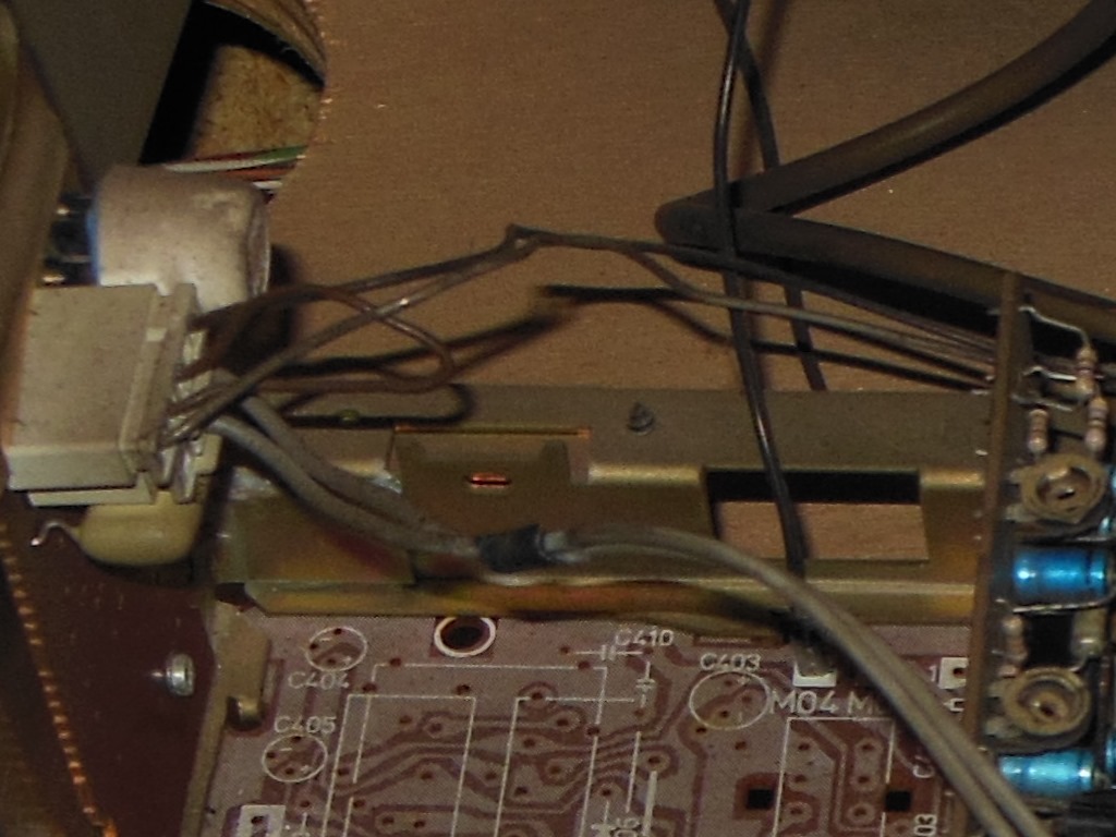
Removing the monitor chassis took a little bit of thought. The chassis is intended to be released by removing a blocking plate on each side that thus opens the cutout in the side plates so the chassis can be lifted out. However, the sides of the cabinet block access to those screws so to do it that way would need the whole monitor removed first :( Instead, the two pins that slide into those cutouts are screwed into the chassis border frame with a couple of small screws. They are right at the back and not visible but are accessible from underneath with a screw driver. Removing the four screws released the chassis.
| Chassis | RGB | Neck | Power | Degauss | Video Input |
|---|---|---|---|---|---|
| M7 connector 3-pin (V. yoke) | "N1" connector 3-pin | L01 pin to CRT DAG | "A1" connector 3-pin | "2" connector 4-pin | P1 connector 6-pin |
| M5 connector 4-pin (H. yoke) | "K1" connector 3-pin | ||||
| M04 pin to CRT frame GND | |||||
| M02 pin to CRT DAG | |||||
| Tripler HT to CRT |
The chassis contains quite a lot of different connectors so I made a note of what was disconnected to be able to properly put it back together later.
|
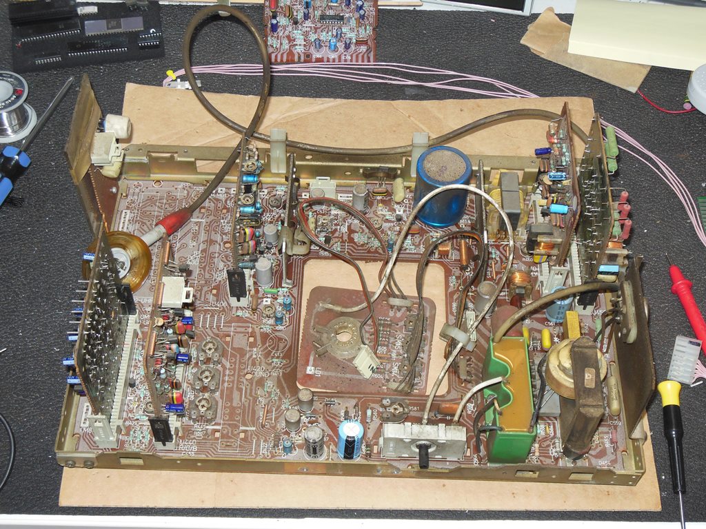
The cap kit was straight forward to apply with no anomolies. I didn't bother replacing C460, the multiple value part. I also sanity checked the transistors in the sync & linearity circuits on the chassis but didn't find any obvious problem.
| CHASSIS '1' |
|||
|---|---|---|---|
| Location | Original | Location | Original |
| C422 | 2.2uF 40V |
C510 | 100uF 10V |
| C460 | * |
C521 | 470uF 25V |
| C464 | 100uF 25V |
C522 | 220uF 10V |
| C484 | 10uF 40V |
C531 | 100uF 25V |
| C492 | 1uF 63V |
C542 | 22uF 40V |
| . | . | C561 | 4.7uF 50V |
| . | . | C582 | 10uF 63V |
| . | . | C583 | 47uF 250V |
| . | . | C586 | 100uF 25V |
| . | . | C587 | 1000uF 16V |
| . | . | C588 | 680uF 35V |
| . | . | C589 | 1000uF 16V |


|
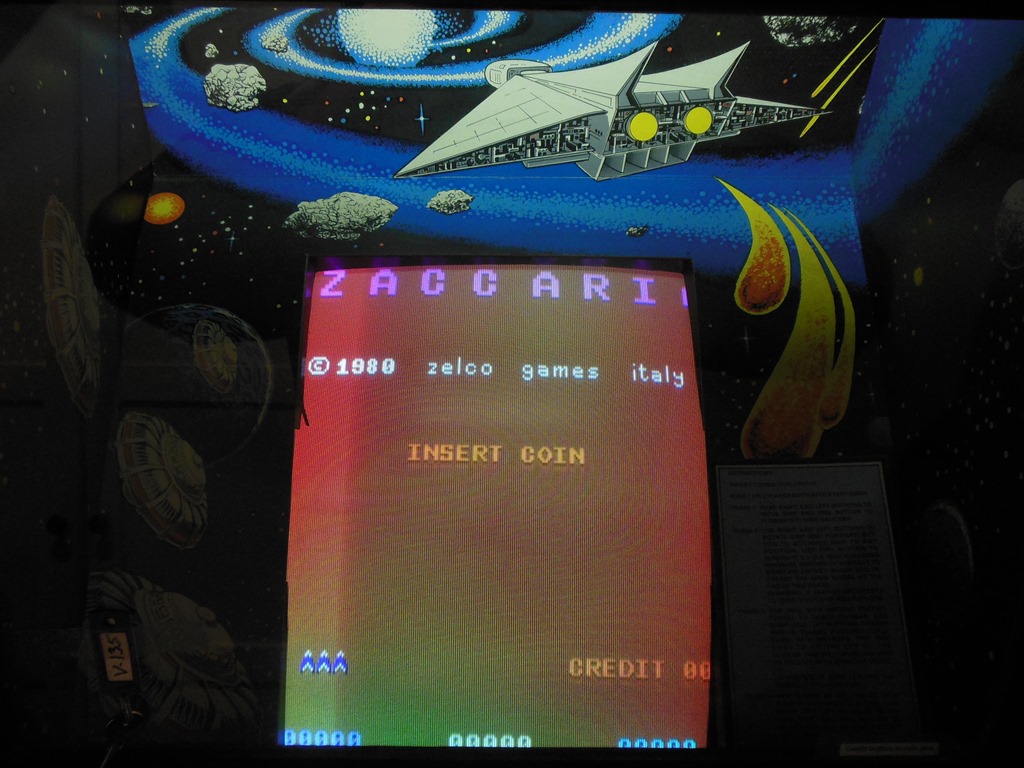
After reassembling the monitor chassis back into the cabinet the re-test showed the picture was fully cleaned up and the sync & linearity issues resolved. I was able to adjust the geometry and other picture settings without issue. The picture looked great. There is still a slight roll/jitter when the game is flat cold but it clears up in few seconds.
|
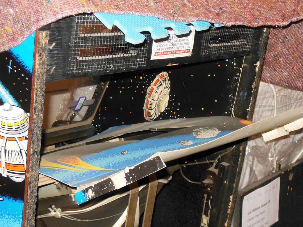
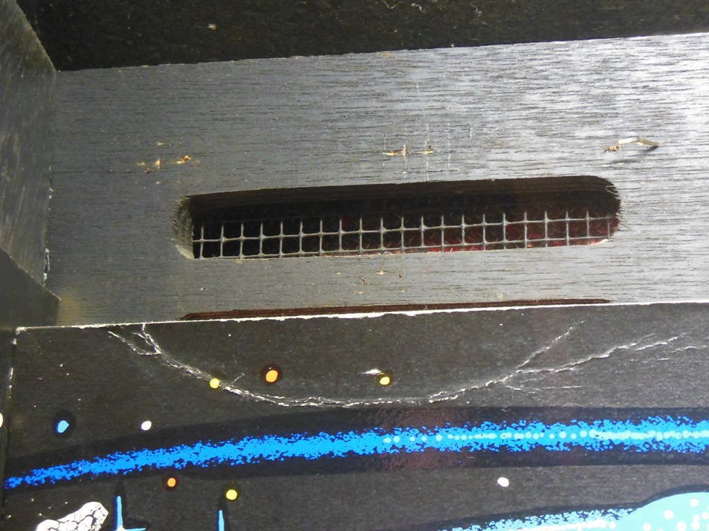
This cabinet has always had gap between the top back of the monitor surround and the opening for the marque light. The top is open and it allows the light from the marque light to be indirectly reflected into the monitor cavity. The arrangement is similar to the native Zaccaria cabinet that has a black light in the front just below the monitor glass that lights up the interior surround. I had noticed that on the US Billiards edition it seemed a little odd to be able to see the back vents from the front. On closer inspection I noticed some staples in the wood suggesting that there had been another piece of interior cardboard trim fitted that covered the vents. At the time of writing I don't know what this was.
|
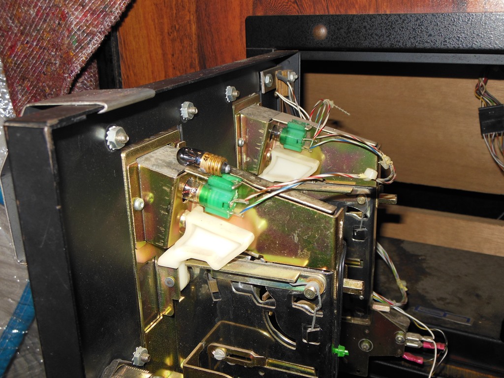
The cabinet does not have the same coin door as the native Zaccaria cabinets so I needed to order #40 6.3V 1W screw bulbs to replace the burnt out coin door lights (the native Zaccaria coin door light bulbs are #47 6.3V 1W press-latch bulbs).
|
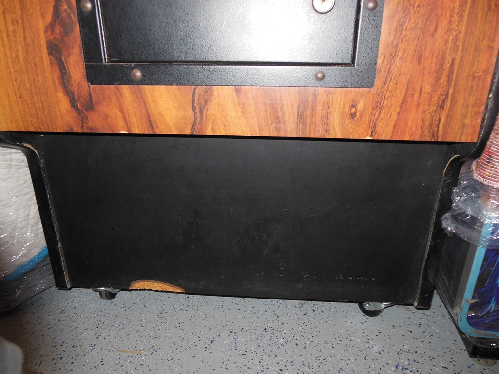
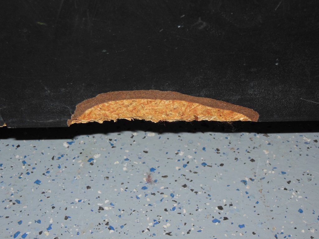
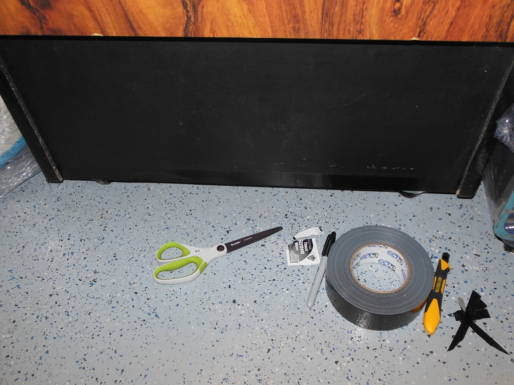
The cabinet has a chip out of the black laminate that covers the kick plate area. Rather than attempt to directly patch or attempt to replace the laminate I decided to simply cover it with a strip of matte black duct tape. The strip is barely noticeable and also adds a little bit of protection for the remaining edge of the laminate.
A video of Quasar game play through all four phases taken on this cabinet.


|
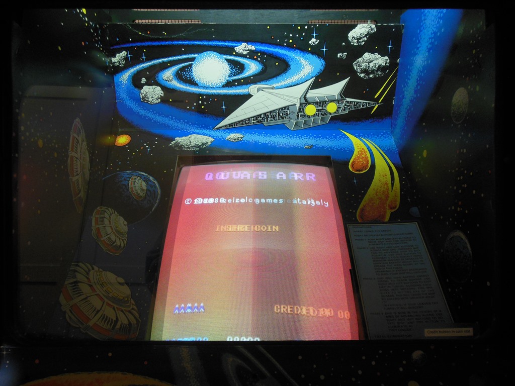
I needed to fix a Quasar PCB for friend that passed all the in-circuit memory tests but had some colour issues. Red was missing in places, notably from the attract mode text and on sheet 3 aliens. This turned out to be nothing more than a bad contact on the colour PROM that was fixed with a re-seat. For future use as a reference I took a photo of the screen display for a complete memory write of data == address using the in-circuit tester.