|
|
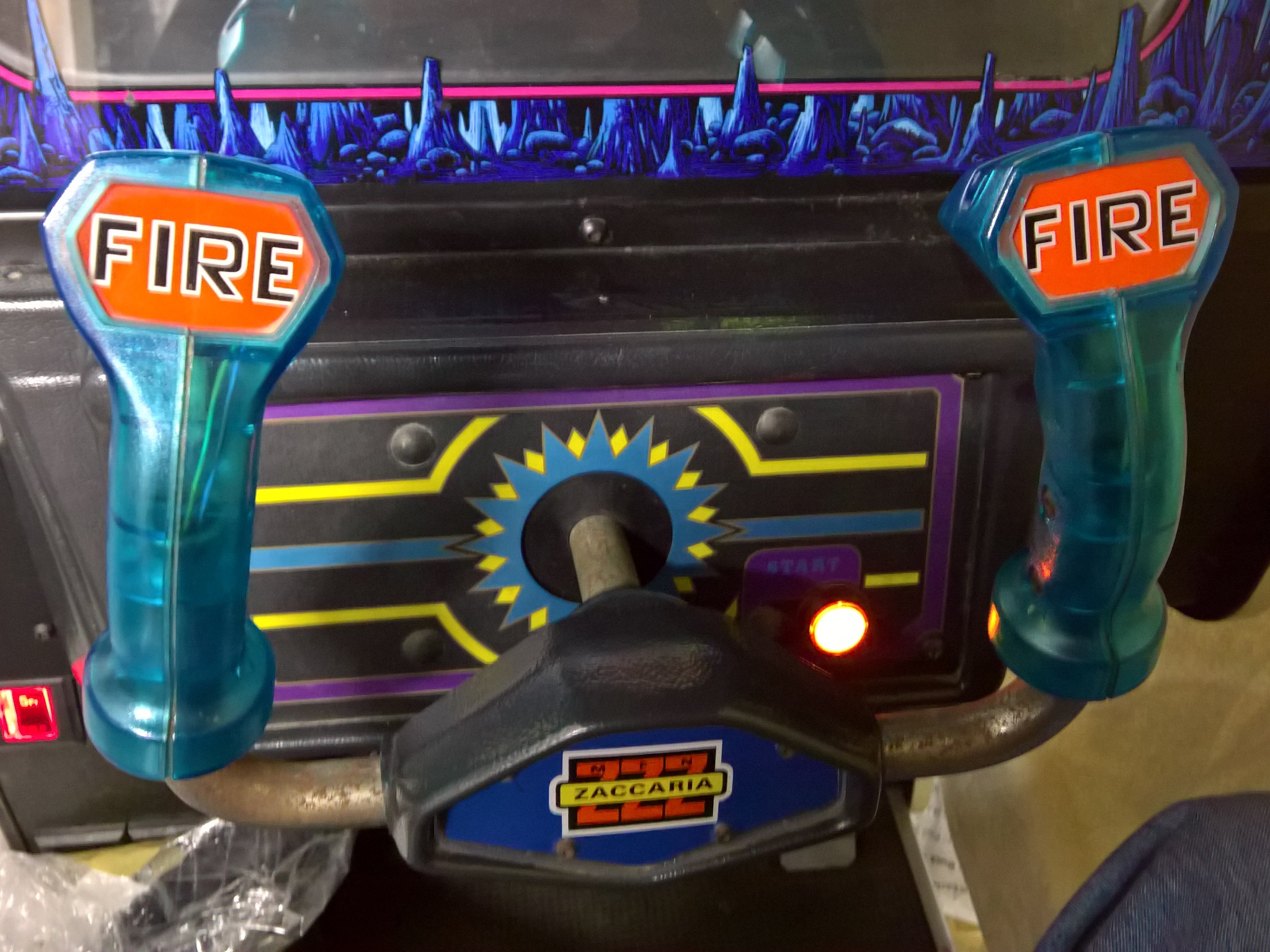
The game ran mostly OK throughout the show except for a couple of minor issues - the explosion sounds were sometimes missing and the start button bulb no longer flashed.
|
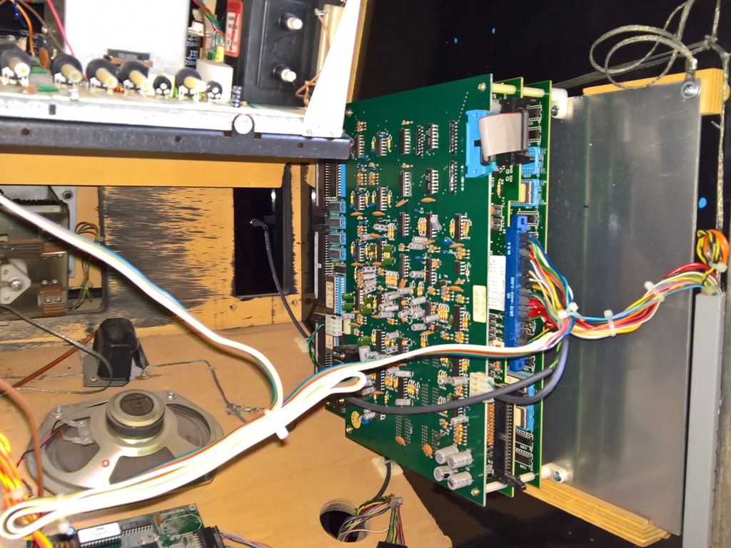
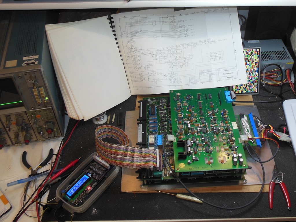
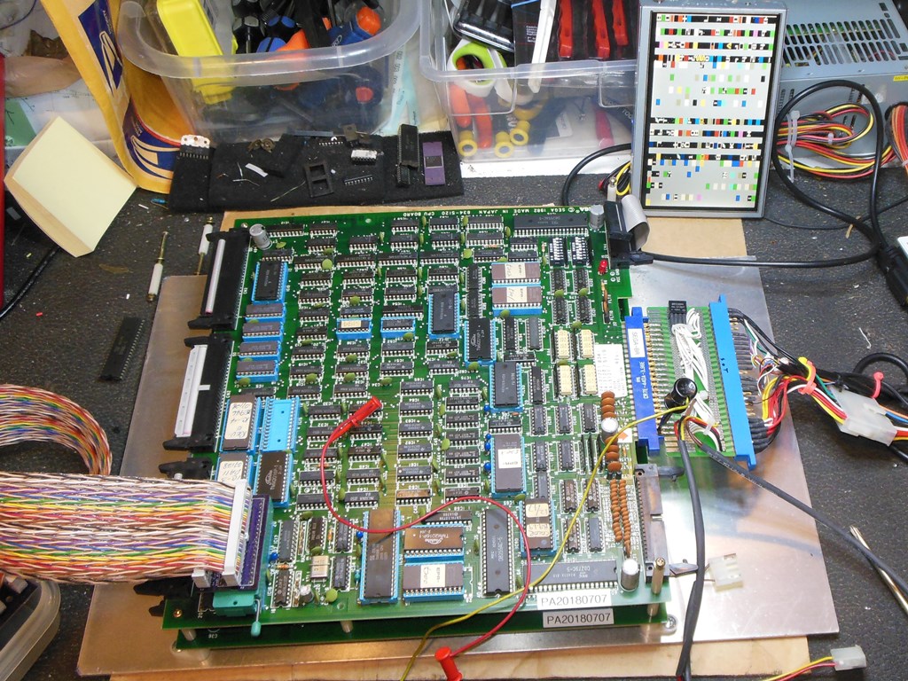
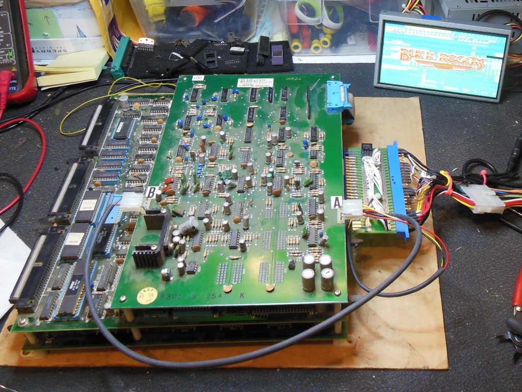
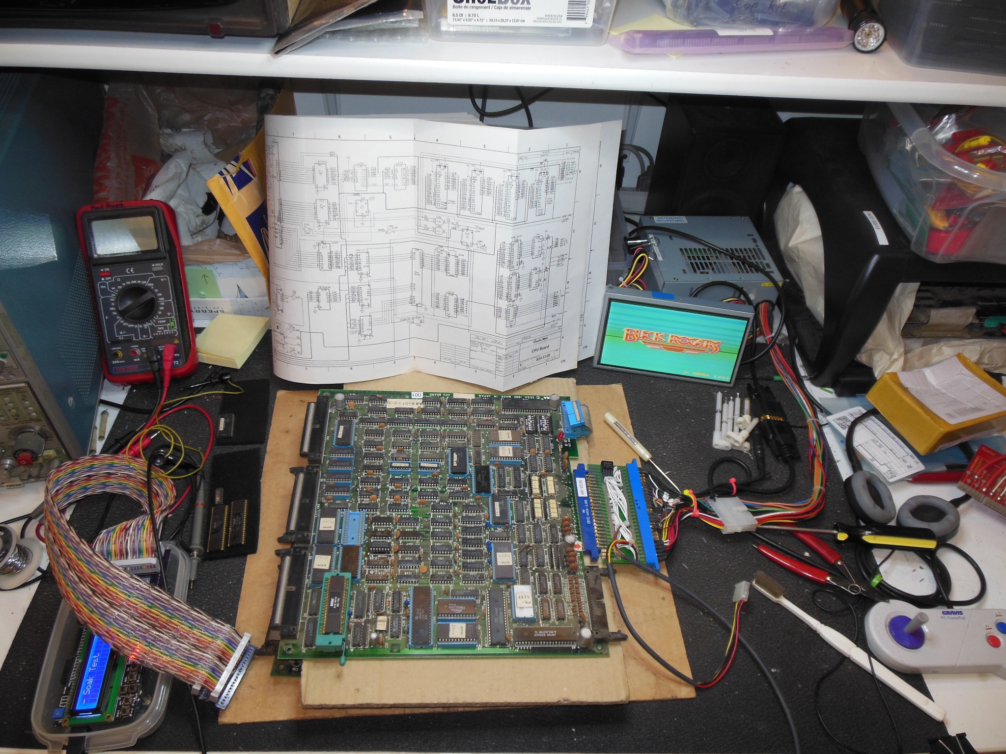
The game PCB was removed from the cabinet for investigation of the sound issues. To ease debugging I added support for Buck Rogers to the Arduino ICT.
|
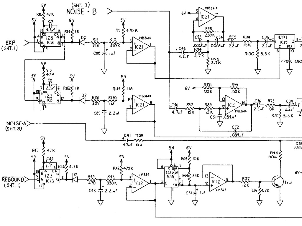
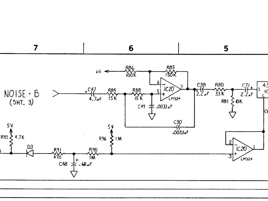
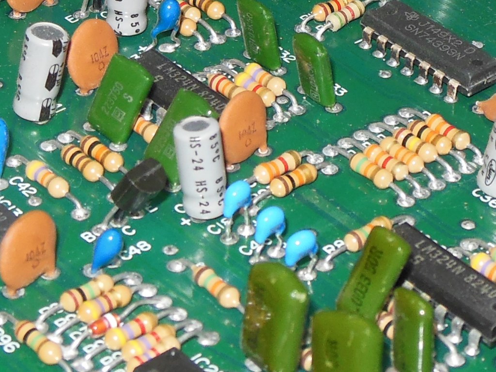
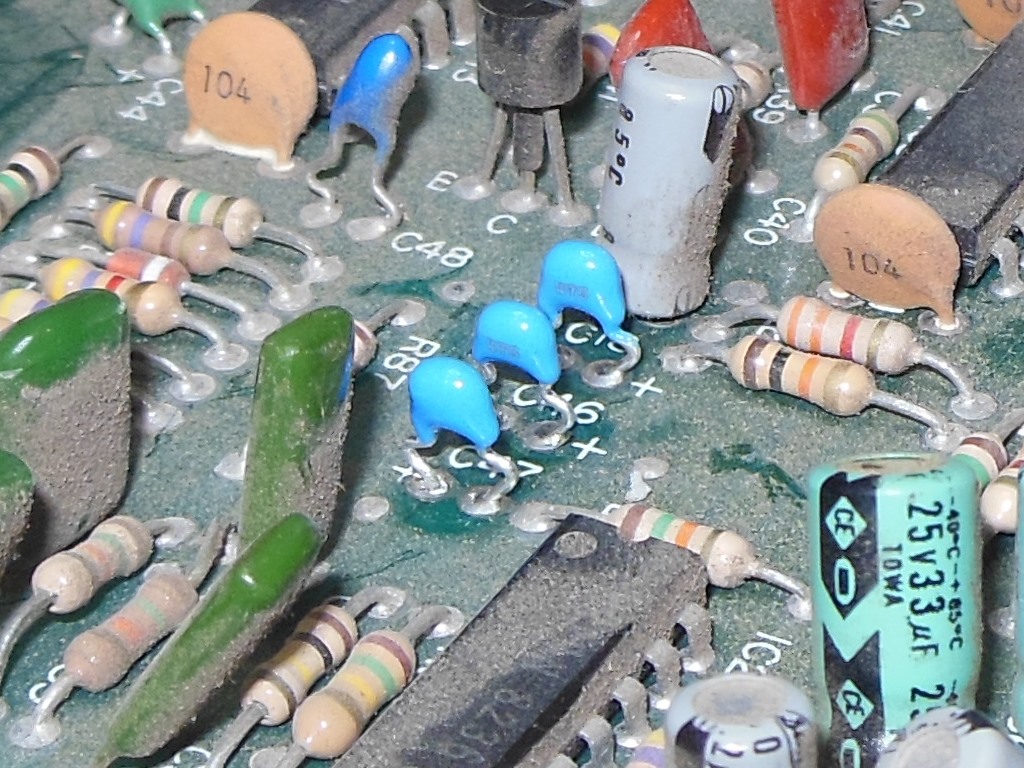
In the prior couple of weeks I'd been investigating explosion issues on Sega Zaxxon. Buck Rogers & Zaxxon were released around the same time and appeared to have some similarities in the sound hardware design so I wondered if Buck Rogers had the same same design error as Zaxxon in that there was a missing DC path in the bias of an op-amp input. Checking the schematics did indeed confirm that the bottom C46 and C47 capacitor inputs from the noise generator into the op-amp had no DC bias path.
|
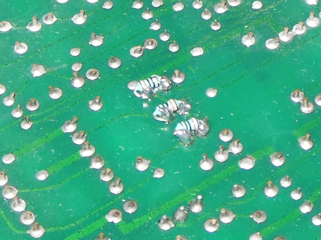
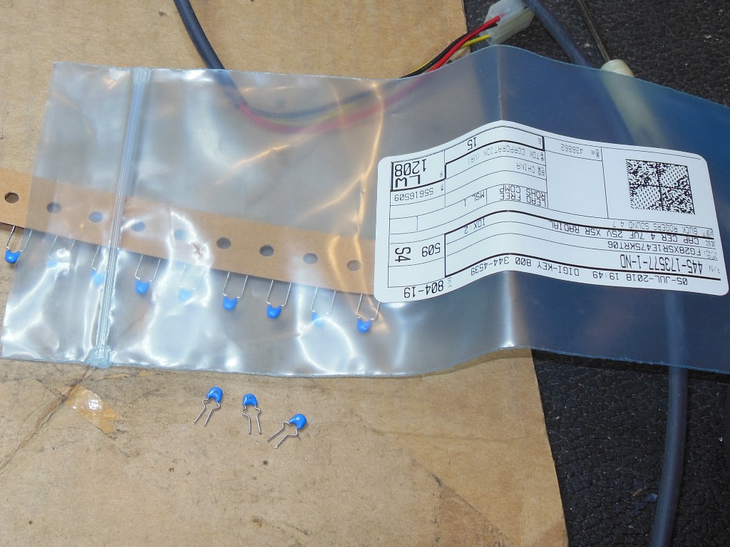
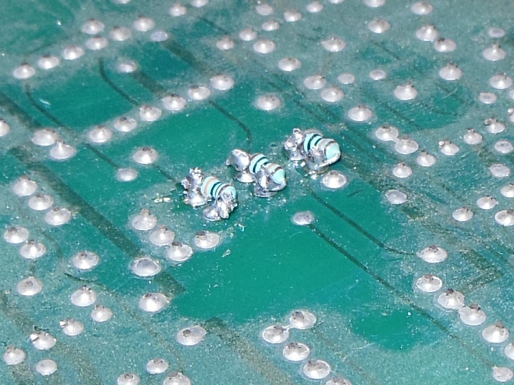
I used a similar fix to Zaxxon - a non-polar capacitor with a resistor accross to
provide the DC "leakage" path. The replacement parts were:-
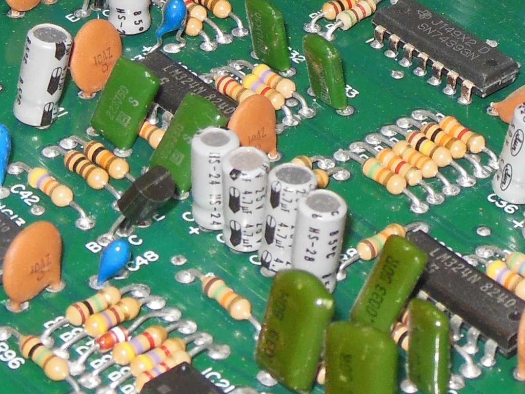
The schematics show two capacitors labeled C46 and I suspected that one was C46 and the other was C48. I could have traced which was which on the game PCB but instead decided to change out all three so that all the "NOISE B" loads were the same to make sure the sound remained balanced between all three inputs. With the design fix there were no further issues with intermittent explosion sounds.
|
Whilst the fully working board set was on the bench I completed Arduino ICT support for testing all of the game. There were some complications as a result of the schematic naming signals with incorrect address monikers. There was also use of WAIT synchronization for video memory access but this still appeared to work correctly with the Arduino ICT thanks to the presence of data latches for the CPU.
|
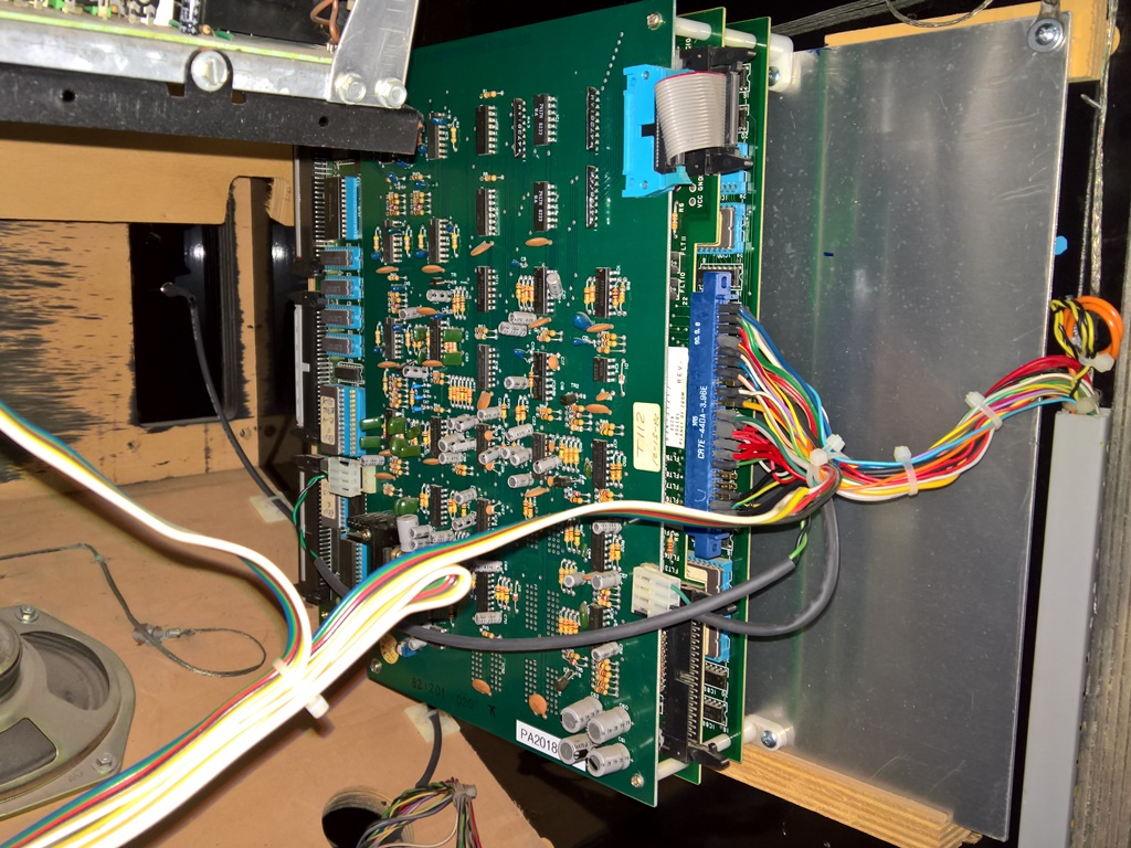
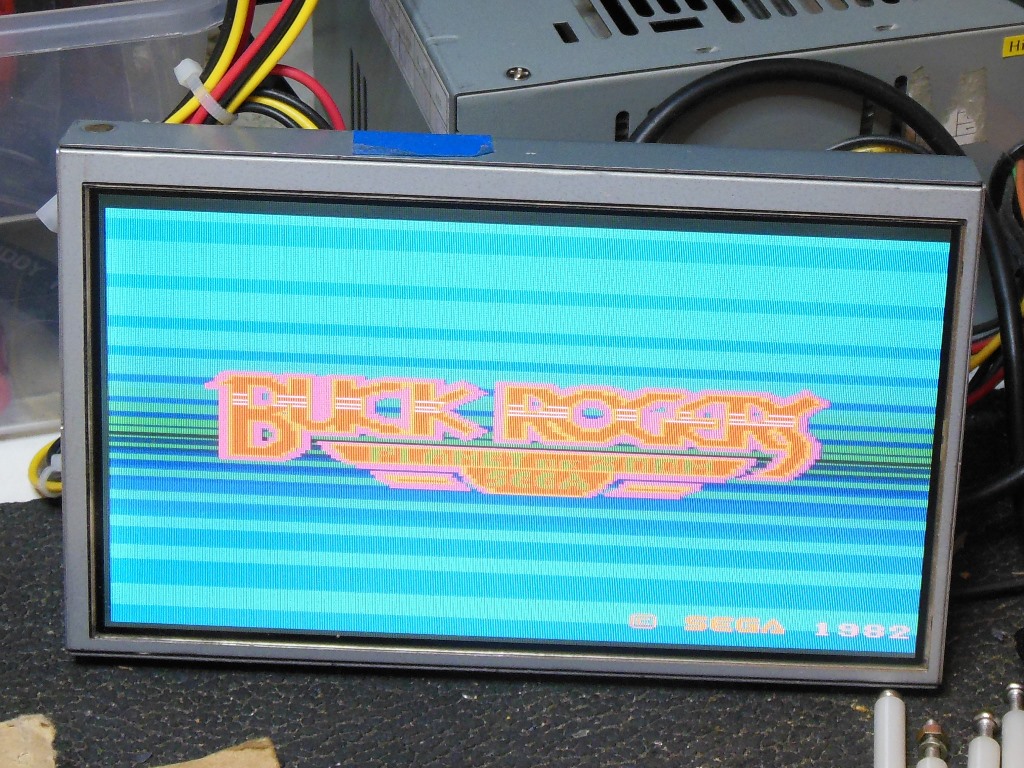
The board set was installed back into the cabinet and the game play tested OK - no problems with sound, video or controls except for the start lamp.
|
I decided to prepare a spare board for the cabinet in case of future board failure. One spare board set already seemed to be working OK except for intermittent explosions so again I applied the noise cap kit & design error fix as had been applied to the previous board set.

|
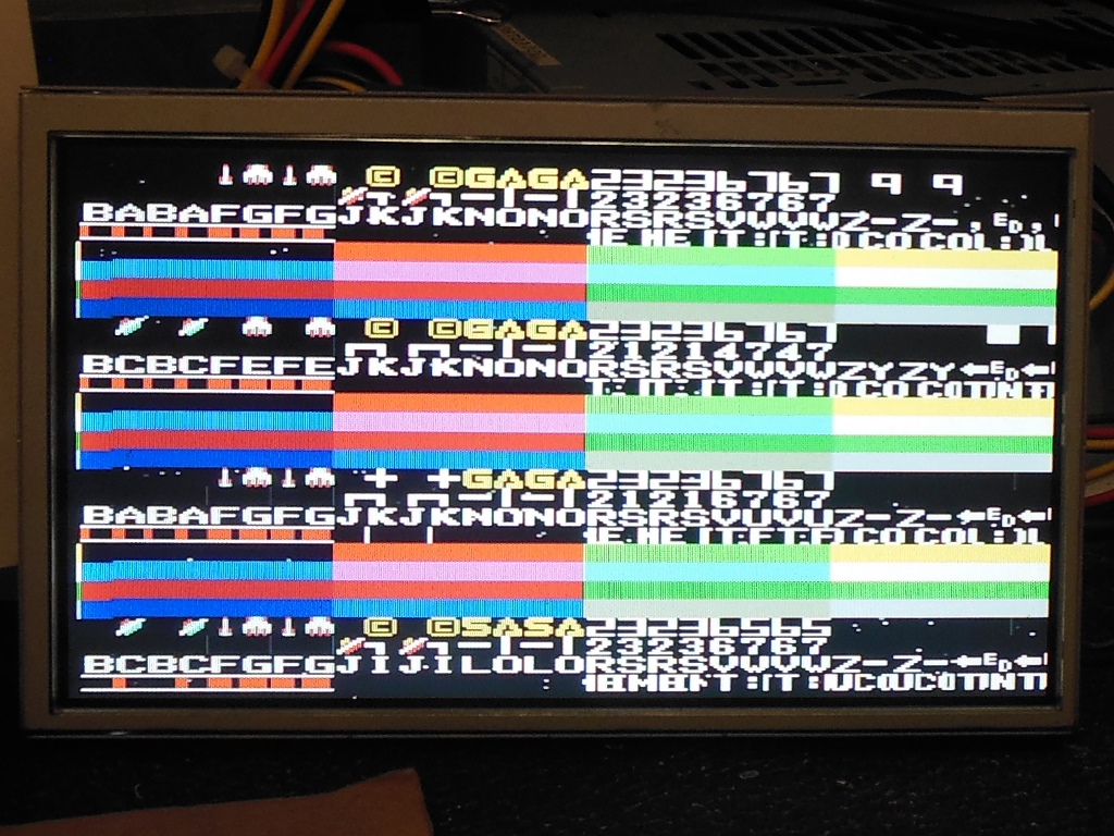
With the sounds all fixed I began a long term bench test of the spare set. After an hour or so running on the bench the graphics became corrupted. Testing with the Arduino ICT reported "E:c84 c000 90 98" and "E:c14 f800 90 4e". The background also flashed during the RAM test of any region. Replacing IC 14 (TMM2016) fixed the c14 RAM test but replacing IC 84 (TMM2016) did not fix the c84 RAM test. The "RAM Write All AD" test displayed "GAGA" where the "SEGA" text should have been suggesting an address problem.
Checking IC's 36,37,38 (LS157) with a scope showed half-sized pulses on the address lines. Checking all three with the HP comparator did not detect any fault with them. Swapping out the timing IC 78 (a PROM) didn't change the fault. Poking around the video/CPU timing circuit found that no Z80 WAIT signal was present on IC 32 pin 8 (LS04). Checking IC 31 (LS74) during RAM test, pin 6 was idle, pin 3 CLK active, pin 4 PR active and pin 2 active. I suspected IC 31 was bad.
|
Replacing IC 31 (LS74) fixed the RAM test. With the CPU installed the board ran with no further issues.

|
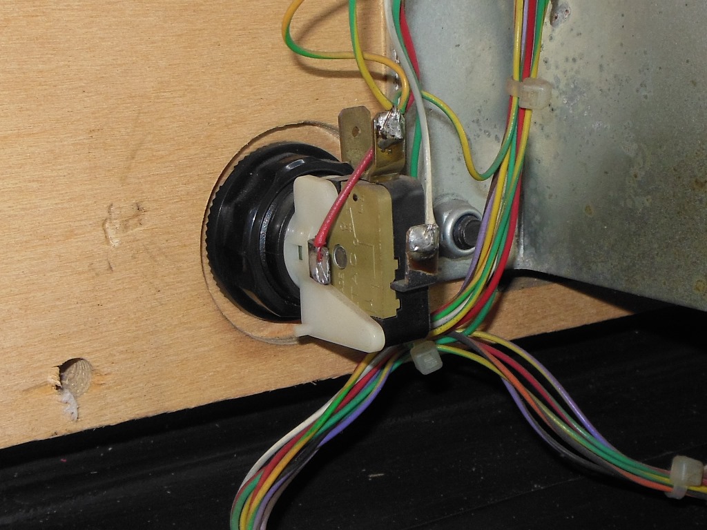
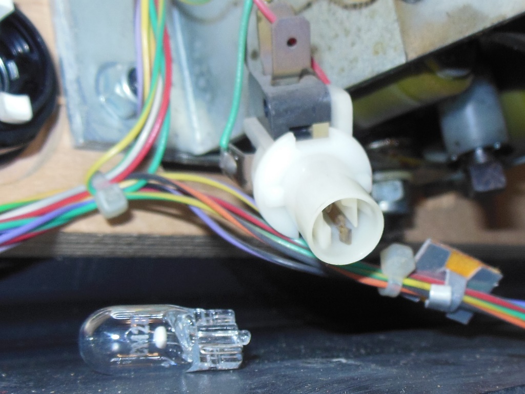
Since I hadn't previously replaced the start lamp I removed the entire control panel assembly to investigate. The design was similar to fruit machine lighted buttons where the switch assembly snaps into the button holder. Removing the switch assembly revealed a CM25 bulb equivalent to the common #555 bulb. A meter confirmed the bulb was open. A new bulb was fitted and the switch assembly snapped back into the button holder. In future it might just be possible to replace the bulb without removing the whole control panel.
|
The control panel was reinstalled in the cabinet and the start lamp was flashing OK.