

|
|
Pre-wrap testing of the game found the star field missing. Swapping in the 2nd working board set yielded a blank screen. With one board set now faulty and the second board set dead the game was withdrawn from the show :(
|
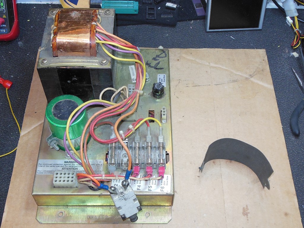
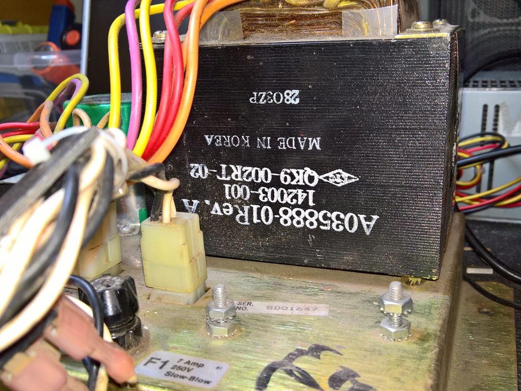
The last time I'd setup to work on Star Wars boards I'd had to use the power brick from the cabinet. Shortly before the 2017 show I'd purchased a second power brick to use for bench testing to save the hassle of removing the brick to bench test with. The brick was supposed to be from the vector game Space Duel and thus compatible with other Atari vector games, but I suspect the seller mistook the SD01647 serial number for meaning Space Duel but it really means it's from a "Sit Down" game. It wasn't the right power brick for running a Star Wars cabinet but for the purposes of bench testing it would run the ARII to power the Star Wars board set OK.
|
Even though the Atari raster power brick would run the ARII, Atari switched out the plug pins (replacing a pin on the vector plug with a socket) to prevent accidentally using the wrong brick. Since I wasn't using the monitor power on the bench I popped out the key pin on the brick to allow the vector plug to fit in the raster brick.

|
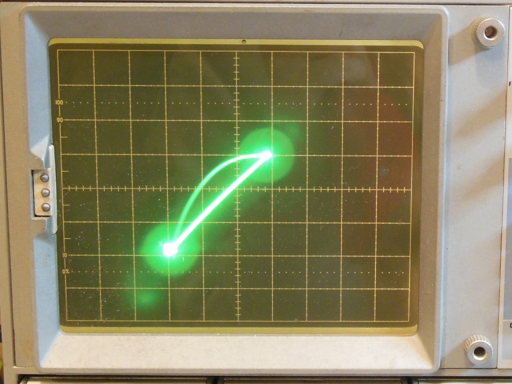
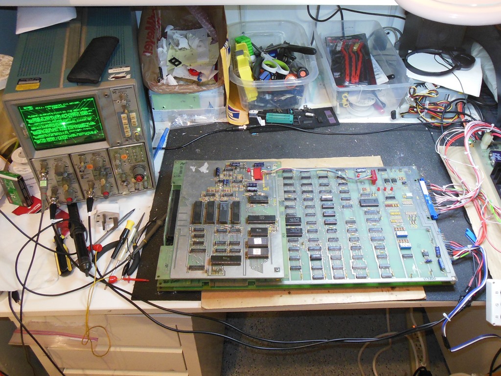
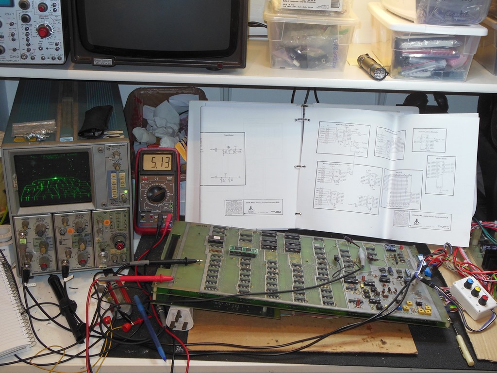
Testing the power supplies on the bench found them all present and correct except for the +5V that measured +4.5V under load. This low voltage measurement traced back to a low +9.28V DC unregulated from the brick. I suspected the bridge rectifier on the brick was bad but a friend more familiar with Atari suggested to check the +5V on a scope to confirm that the smoothing capacitor "big blue" was working. His hunch was correct and the scope showed large ripple on the +5V.

|
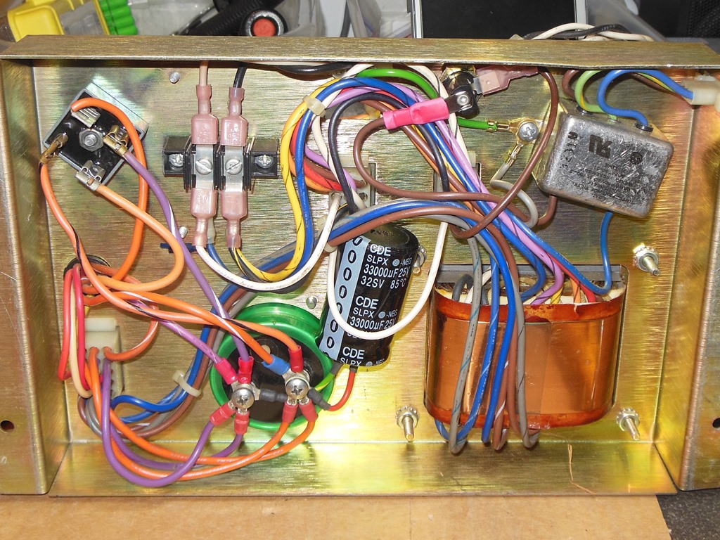
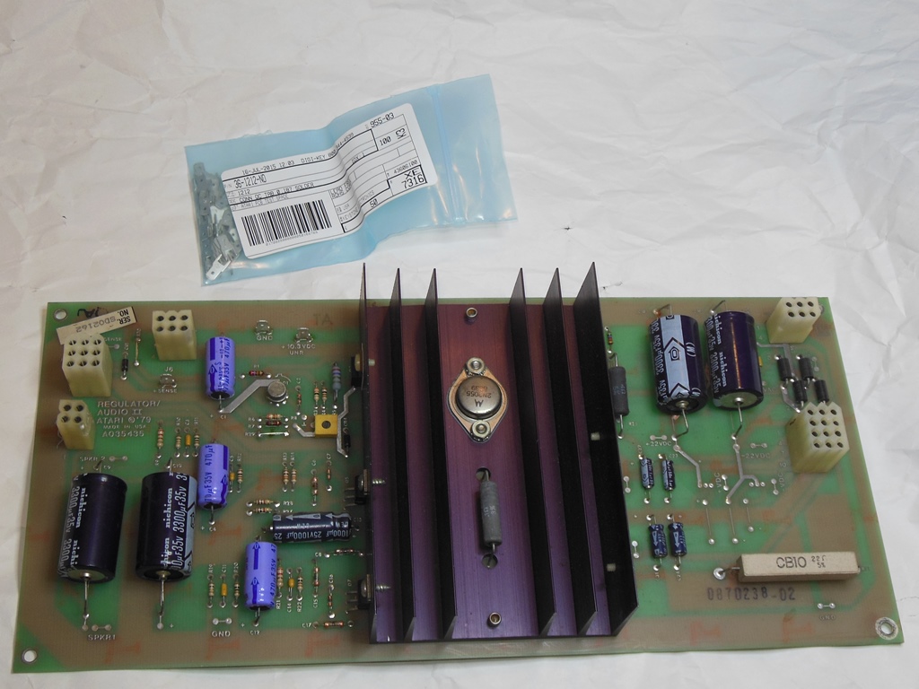
Whilst there are relatively expensive large reproduction capacitors available specifically to fit Atari power bricks, better compact modern equivalents are widely available for a few dollars so I decided to go with one of those instead. Originally I was going to replace but since it'd leave a big hole where the old one was I decided to leave the old one in and just attach the new one along side in parallel. The +5V looked great under load, a solid +5.04V regulated and +12.1V unregulated (with ~1.2V ripple) at the 10.3VDC test point.
Testing with the partially working (no star field) board set on the bench confirmed that the new brick setup was all working OK. On the bench this board set did not have any obvious problems with the star field :|
|
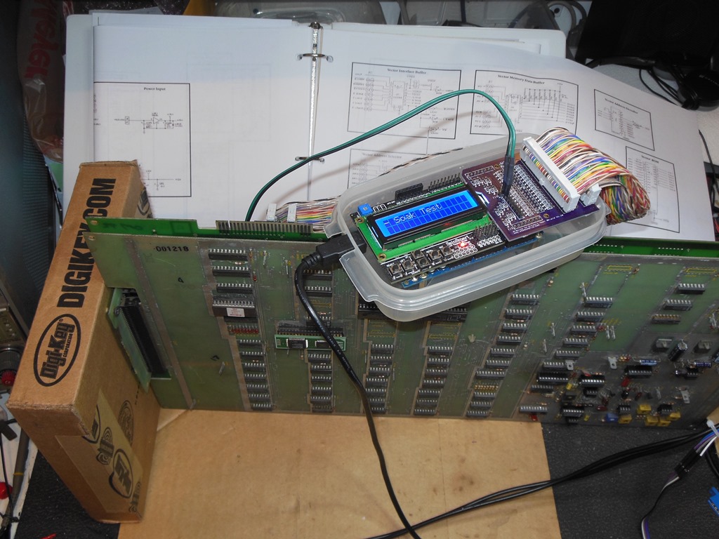
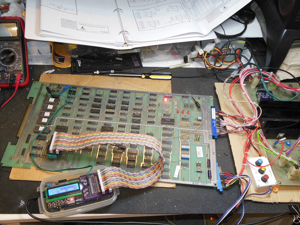
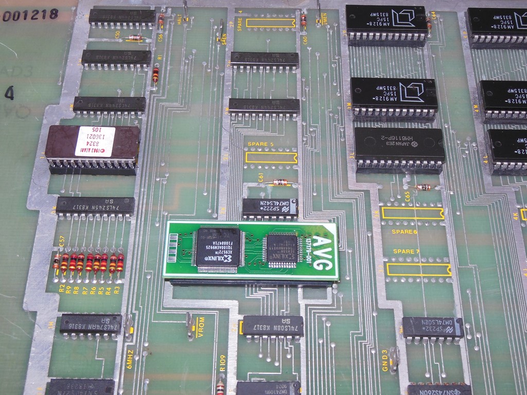
Setting up to work on the dead board set found the board had very little vector output. The watchdog was being kicked and the main PCB appeared to be running. The vector signals HALT, STOP and SCALE were all active. I setup with the Arduino ICT to verify the main PCB that confirmed the ROM & RAM on the main PCB were working OK. I suspected that the problem was with the AVG board that also contains its own ROM & RAM but I hadn't yet added support for that to the ICT.
|
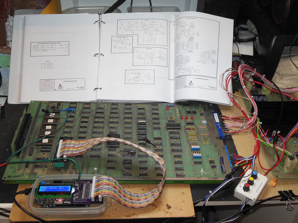
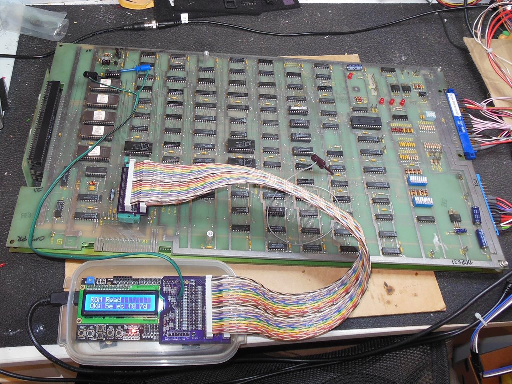
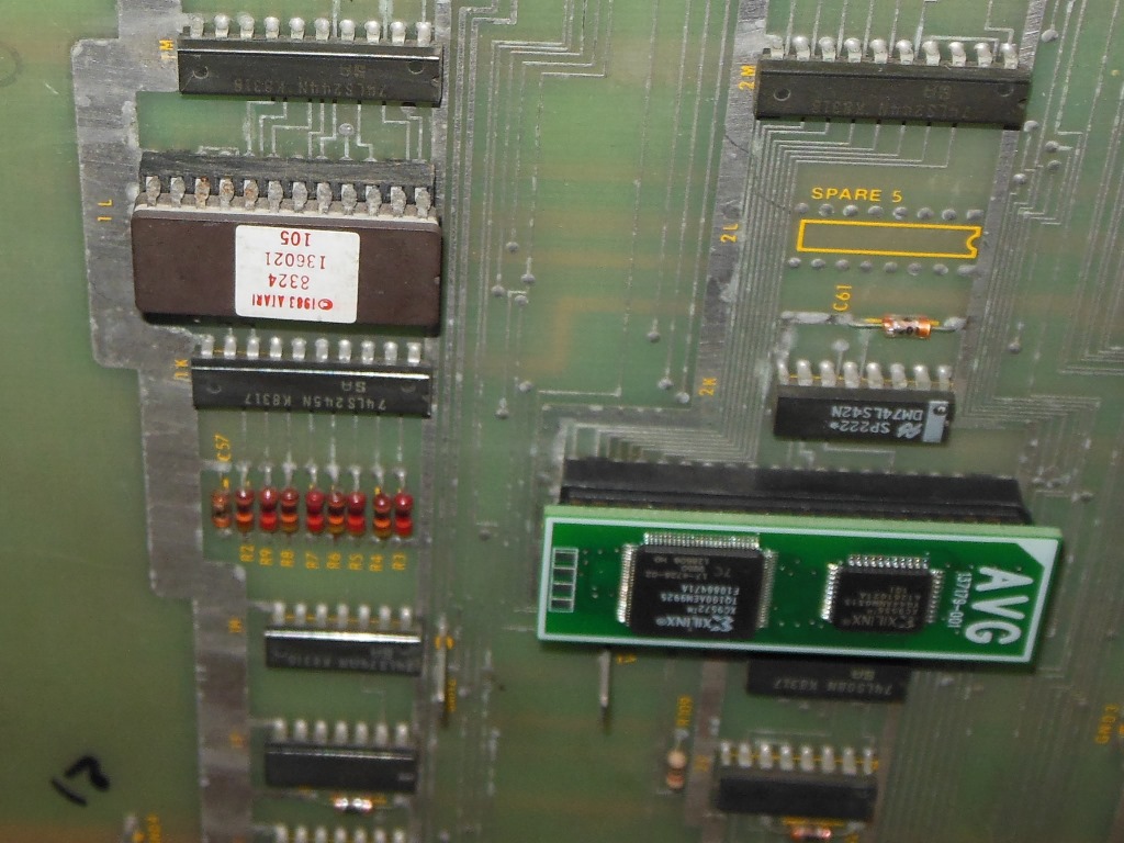
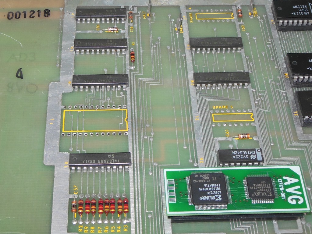
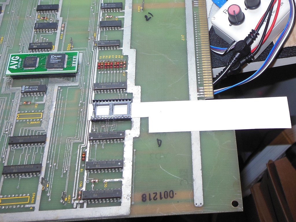
After adding support to the Arduino ICT to cover the Star Wars AVG, the ICT "ROM Check All" reported "E: 1L 3002 b8 f8". A "ROM Read" returned "OK: 5e ec f8 7d" where 1E EC B8 7D was expected, confirming that bit 0x40 was intermittent. A "RAM Check All" passed OK. After adjusting the bench setup to gain access to the AVG board, probing with a multimeter found the vector ROM IC 1L (2716) pin 16 to IC 1K (LS245) open circuit. The ROM pins were rusty so I suspected a bad socket.
|
The AVG ROM socket was removed and replaced with a new socket. Since Atari didn't use a top solder mask, the first attempt to replace the socket failed due to solder bridges on the top side of the board. For the second attempt I made a cardboard spacer to keep the socket slightly higher than the PCB to prevent solder from overflowing the bare pads. The second attempt was successful. After cleaning the ROM pins, reinstalling and retesting I was rewarded with the vector output of a running board that appeared to play through OK on the bench :)

|
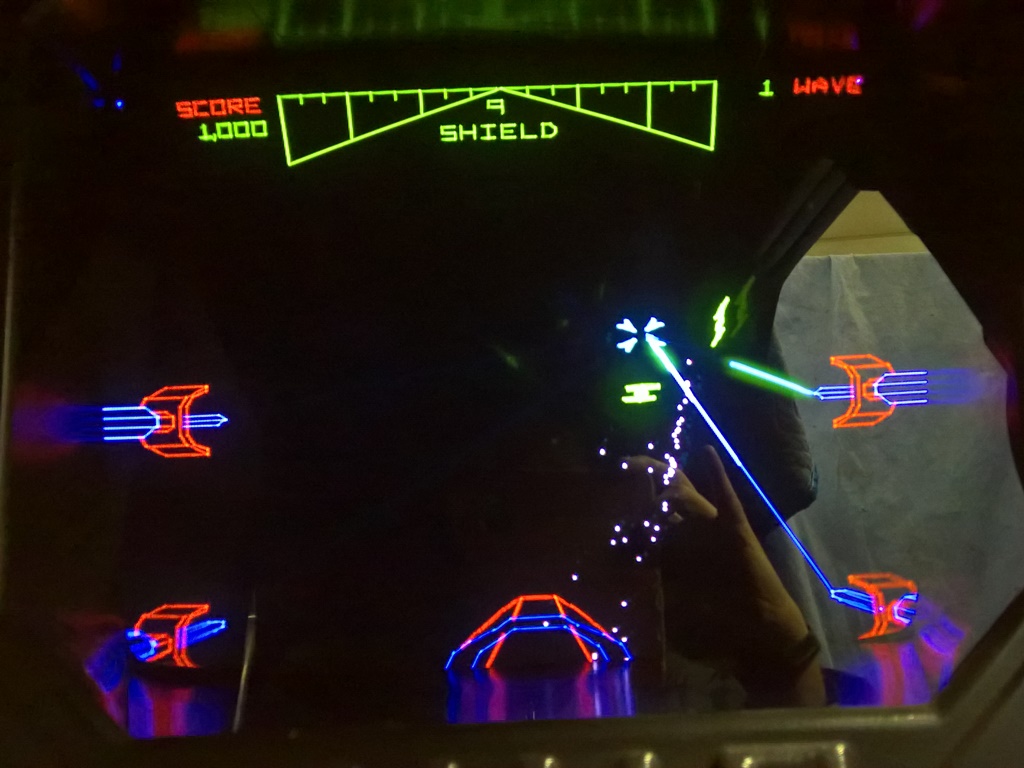
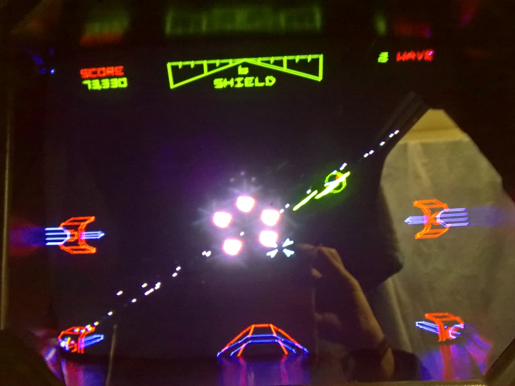
Testing the first board set back in the game found two problems. First, the text was unstable, jumping lines and skipping characters. This was more severe when the game was cold and subsided after some warm up time. The second problem was during the game the tie fighters collapsed flat and the 3D space was mostly compressed into a line. The self-test didn't flag any issue and all of the visual check tests looked good. The board set was pulled to test on the bench.
|
Given at least one of the problems was more prevalent when cold I started out by testing at low (4.80V) and high (5.20V) +5V rails. Low +5V made the vector problems much worse and high +5V eliminated both issues. I thought that maybe I could get away with simply increasing the +5V in the cabinet to alleviate the problem. Before I concluded testing, however, the self-test began reporting a divider error.
|
I'd already walked this path before so I began walking it again and setup the Arduino ICT to test the divider. The ICT reported "DV Test 21 4000 4007" and "DV Test 22 5555 5557" confirming the self-test results. I started out with DV Test 21 and looking at the outputs of IC's 6L, 6P, 5P & 4P (all LS175) that confirmed 0x4000 was properly latched in the DVSR latches. Looking at IC's 5J and 5K (LS164) confirmed the bad result 0x4007 was present on the outputs (so the result data bus buffers 4J & 4K (LS244) were likely OK). Moving to the adders, since they were already socketed I swapped them around but the incorrect result didn't change. Similarly swapping IC's 4M & 5M (LS374) didn't change anything either. IC's 5J & 5K (LS164) both passed OK with the HP comparator. That really only left IC's 3N & 7N (LS299). Since these were neither socketed or compatible with the HP comparator, I speculatively tried a simple piggyback of another LS299 and the test began passing with IC 7M piggybacked. Replacing IC 7M (LS299) fixed the divider :)
|
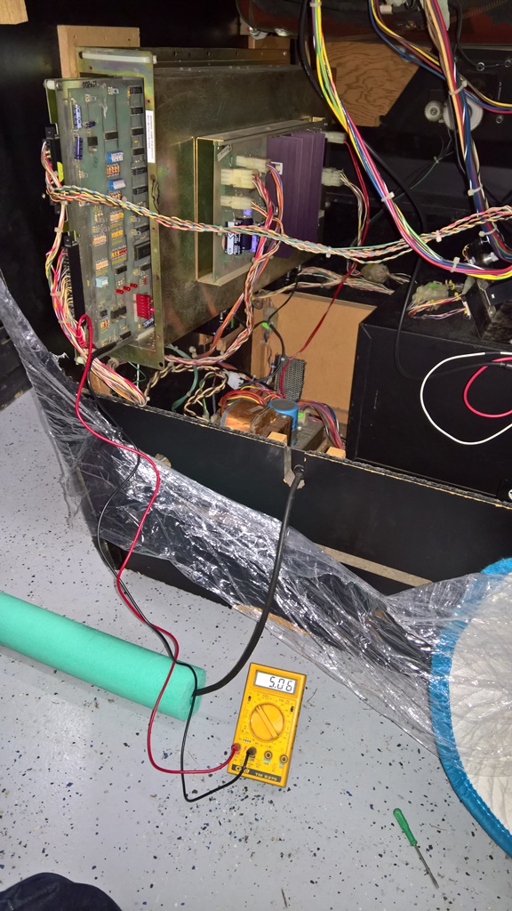
The plan was to increase the +5V to about 5.13V to be able to get past the vector problem. However, even with the AR II turned up all the way it could only manage 5.06V to the test tabs on the main PCB, not quite enough to clear the vector problem. I pulled the AR II to verify on the bench.
|
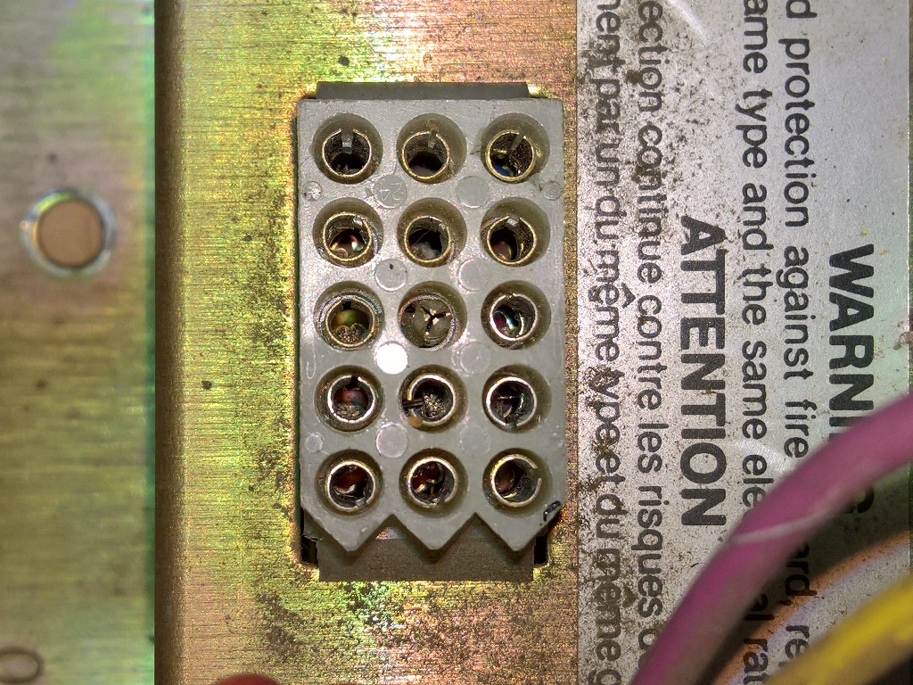
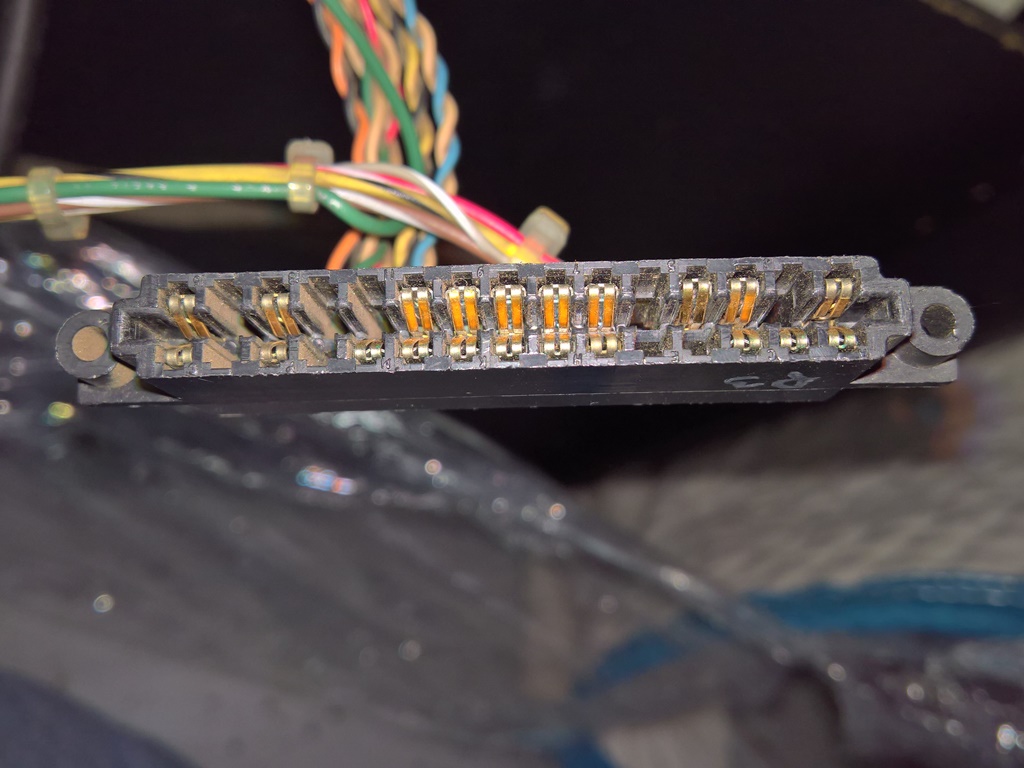
Testing the ARII one the bench didn't find any problems with it and it was able to output to 5.23V with a dummy load. The voltage test tabs hadn't been populated so I took the opportunity to fit them to allow a meter to easily clip on to measure voltages and as a fall back if I needed to use them to add additional power distribution. Given that the ARII was OK I suspected that the edge connector pins were worn out :(

|
It's common for a power supply voltage susceptible issue to also be thermally susceptible and I already seen the jittery text clear up when the board set was warm. Going over the AVG PCB IC by IC with a drop of freezer spray found nothing on the AVG PCB itself, however the reproduction AVG was massively impacted - when cooled there was massive vector corruption. I ordered three reproduction AVG's, two from eBay at 2 for $33.50 and one from ArcadeShop at 1 for $32.45 all in.

|
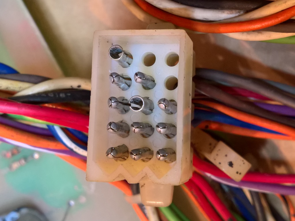
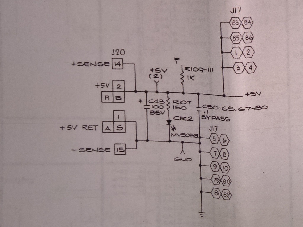
Investigating the cabinet found a lot of +5V power loss through both the cabinet wiring and edge connector pins. The cabinet has the sense mod done (to repurpose the sense lines as additional power lines) that improves the power distribution to the main PCB but doesn't help with the AVG PCB.
|
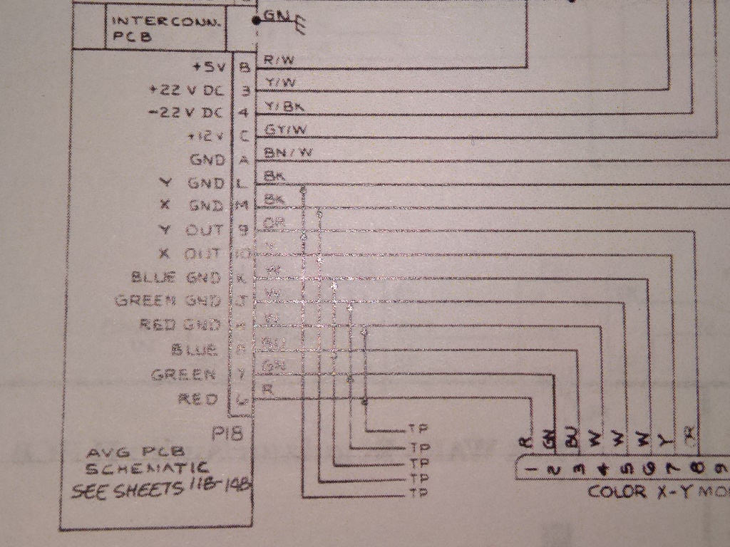
According to the manual the AVG PCB provides three +5V and three GND connections plus a pair of sense lines, total 4 connections each for +5V & GND. However the cabinet wiring only connects a single +5V and a single GND wire for the AVG from the ARII. Thus, the problem here was both a design error in the power distribution for the AVG PCB and likely worn out edge connector power pins. There wasn't quite enough time to address this before the show since I had no replacement edge connector pins to hand.
|
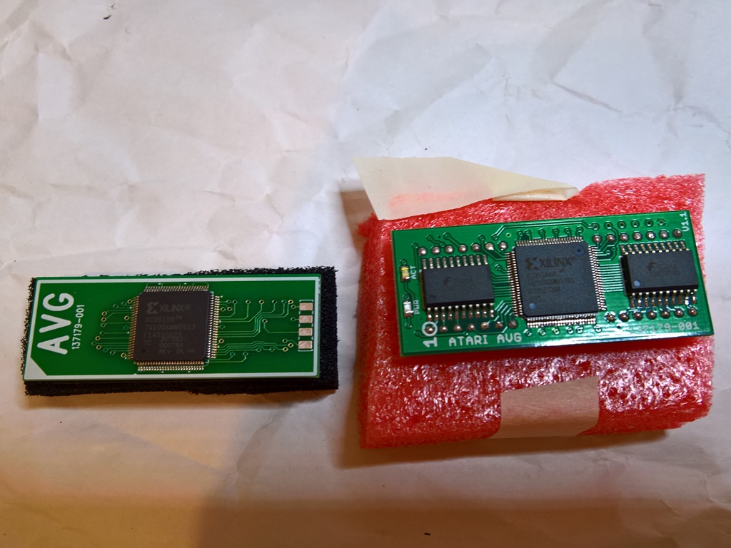
The replacement AVGs arrived, two from eBay (on the left) and one from ArcadeShop (on the right). The eBay ones were half the cost of the ArcadeShop ones. In terms of differences, the eBay version uses a single +5V Xilinx FPGA and has pins close to the same size as IC pins. The ArcadeShop version uses a 3.3V FPGA with level shifters back to +5V and has thicker pins (stressing the socket more than the eBay one). In use, both replacements worked OK with no issues however the eBay version ran a lot hotter than the ArcadeShop version. Since in cabinet the ambient temperature would be quite high (even with the four fans installed) and the run time many hours at the show, I decided to use the ArcadeShop one to start with.
The game was reassembled, tested out OK & wrapped for shipping to the show.