|
|
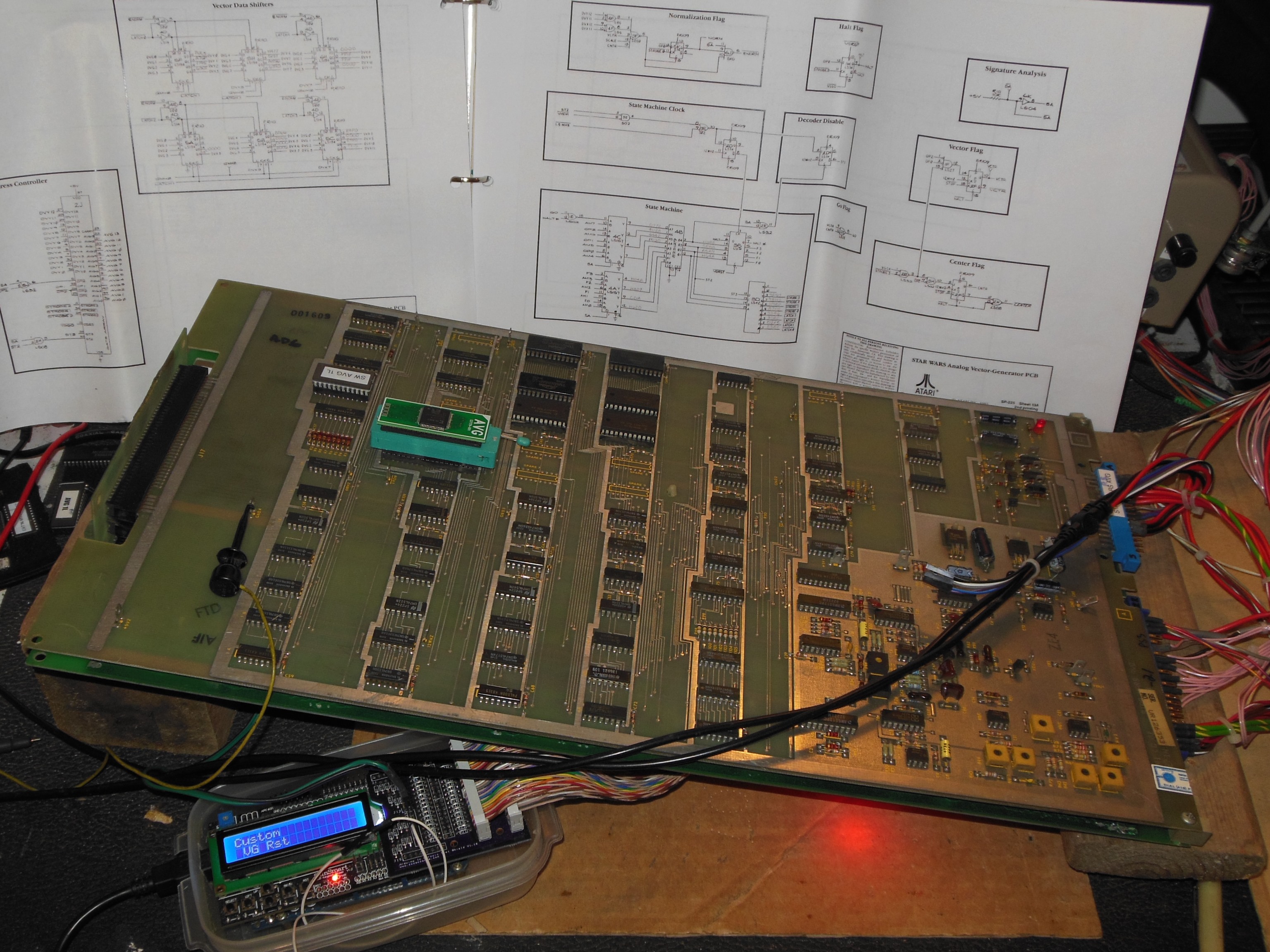
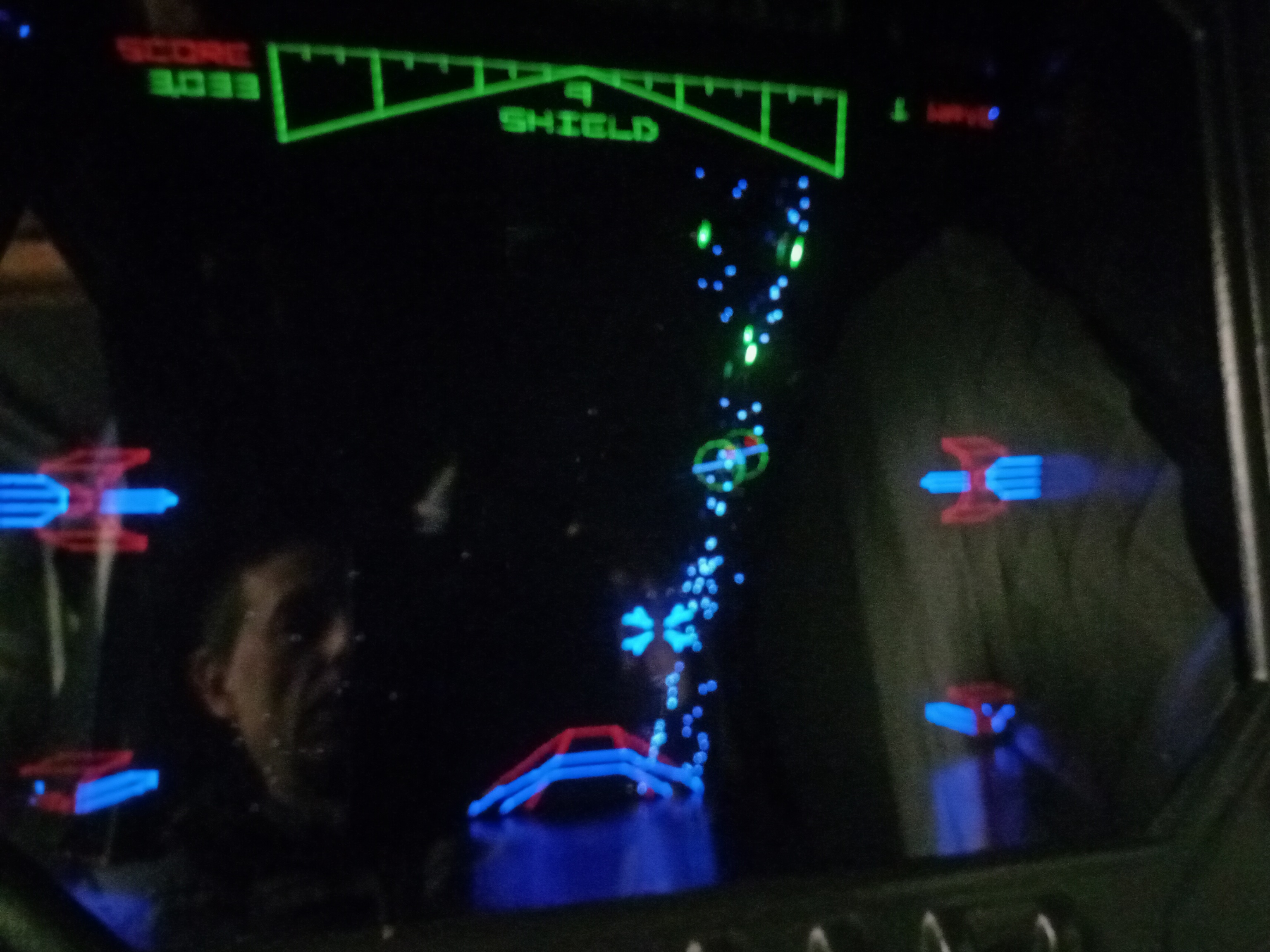
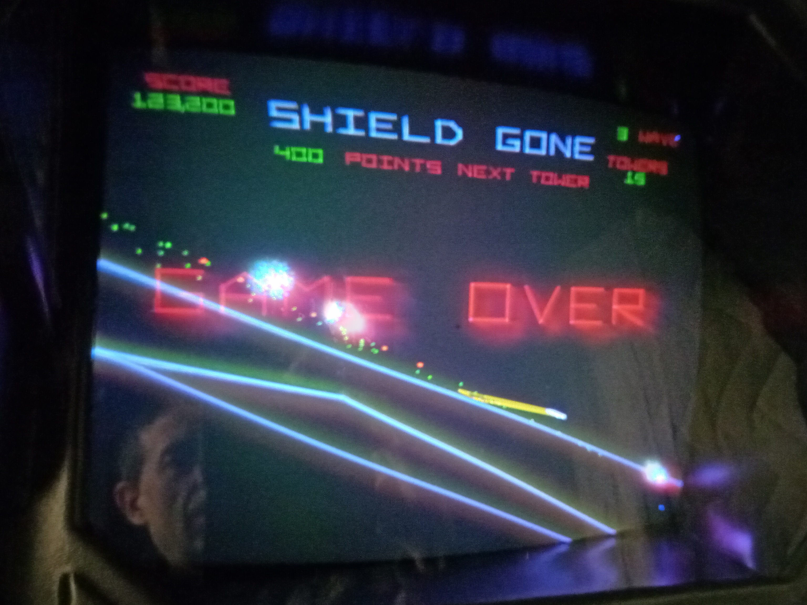
The game ran for a few hours after initial setup before the tie fighters had problems. Self test reported matrix errors and a spare game PCB was swapped in. On show day 1 the game ended up dead with no picture. Suspecting the AVG PCB had died and with the math box being on the main PCB, the main PCB from the backup set was coupled with the AVG PCB from the primary PCB. This succeeded in getting the game running again and it almost made it through to the end of show, succumbing to missing tie fighters & matrix errors again part way through the last day.
|
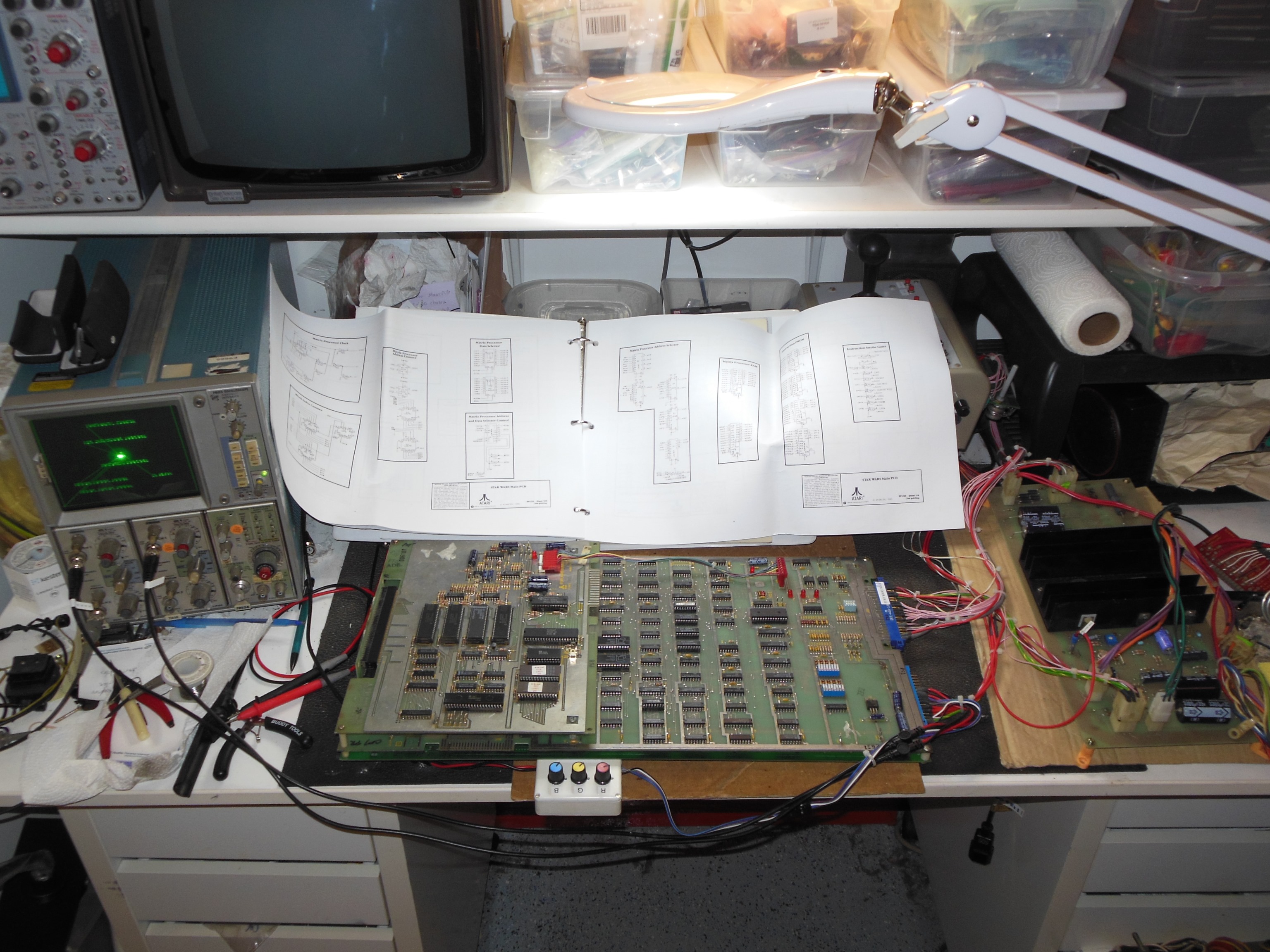
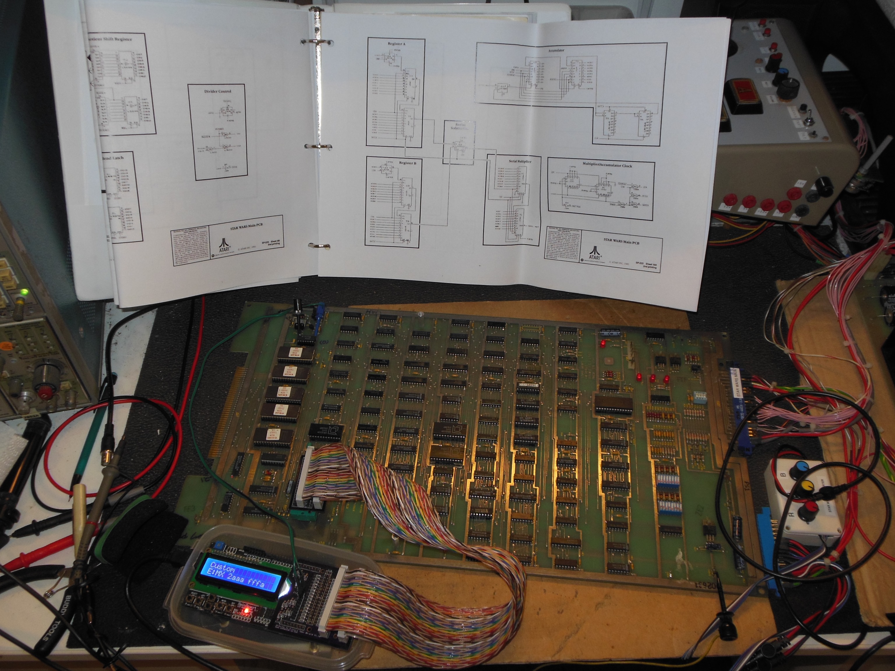
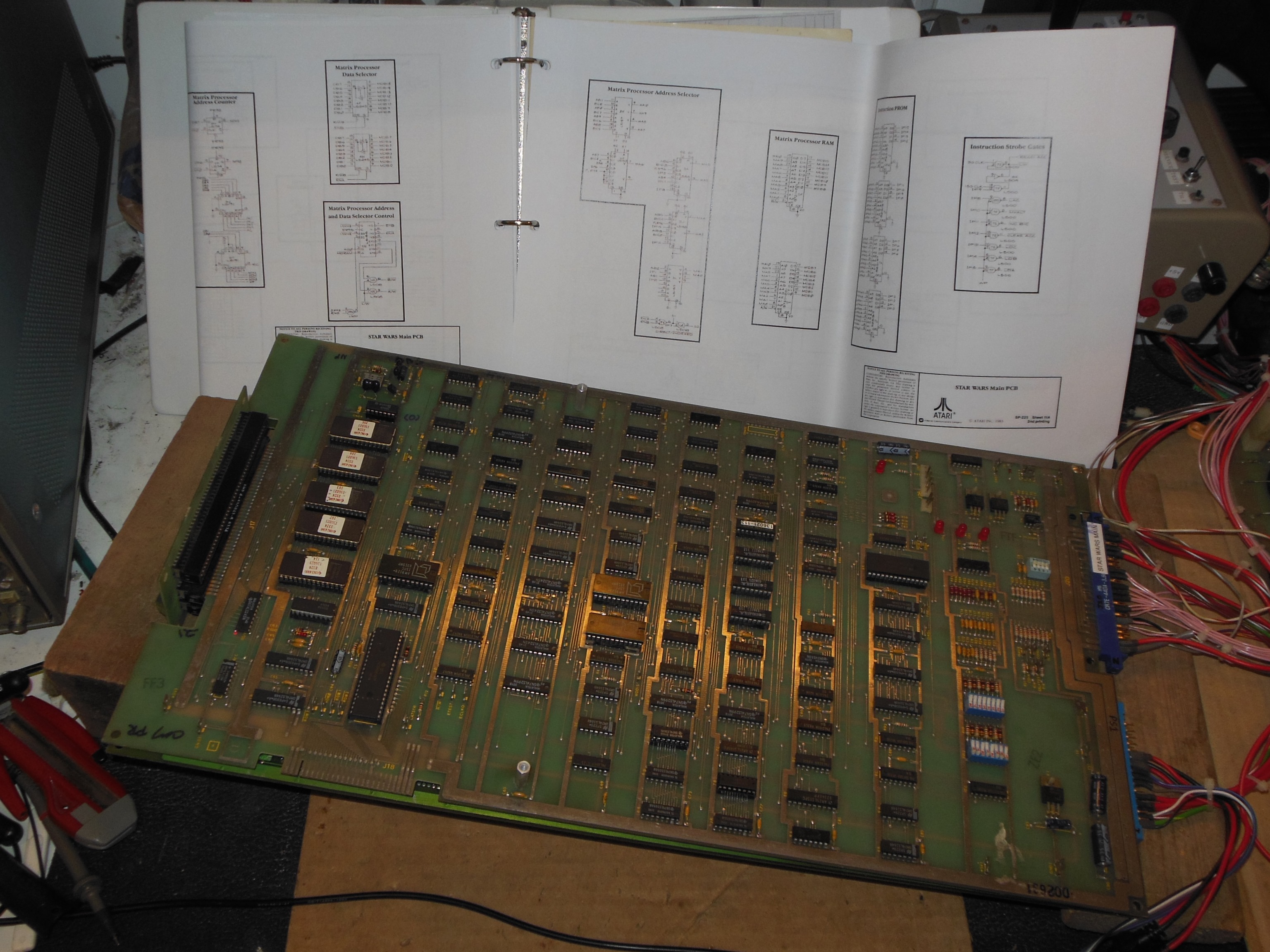
On the bench the game ran with no tie fighters and test mode reported matrix errors. Splitting out the main PCB and setting up the Arduino ICT found ROM, RAM & divider tests passing OK but matrix test 18 "E:MX 5555 FFF5" and 20 "E:MX 2aaa fffa" failures. Using Arduino ICT signal captures found:
Comparing the two MX tests the 7A and 7B shift outs didn't match. I suspected IC 7B (LS165) was bad and I fitted a piggyback replacement over the top with pin 9 bent out to capture a reference:
7B pin 9 : 00 fe aa a8 - 00 00 00 00The piggyback gave an MX Test 18 sequence matching the corresponding MX Test 17 sequence and replacing IC 7B (LS165) fixed all the matrix tests.
|
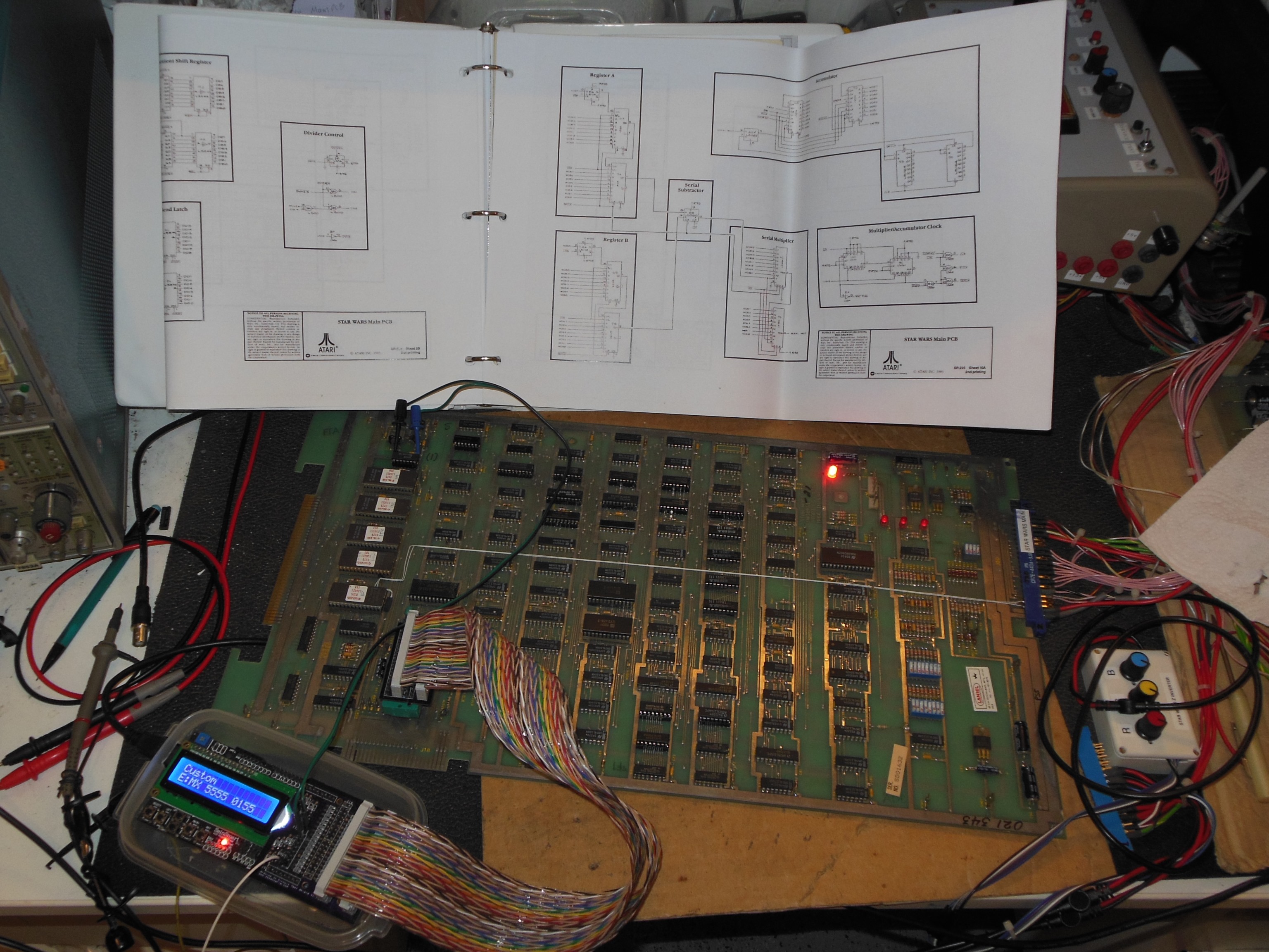
Setting up the Arduino ICT found ROM, RAM & divider tests passing OK but matrix test 17 "E:MX 5555 0155" and 19 "E:MX 2aaa 02aa" failures. Using Arduino ICT signal captures found:
I suspected IC 6A (LS165) was bad and fitted a piggyback replacement over the top with pin 9 bent out to capture a reference:
6A pin 9 : 1f fe a8 00 - 00 00 00 00The piggyback gave an MX Test 17 sequence matching the reference captures. Since this was the second LS165 to fail on this PCB I decided to speculatively replace all the remaining LS165 ICs 6A,7A,7B that fixed all the matrix tests.
|
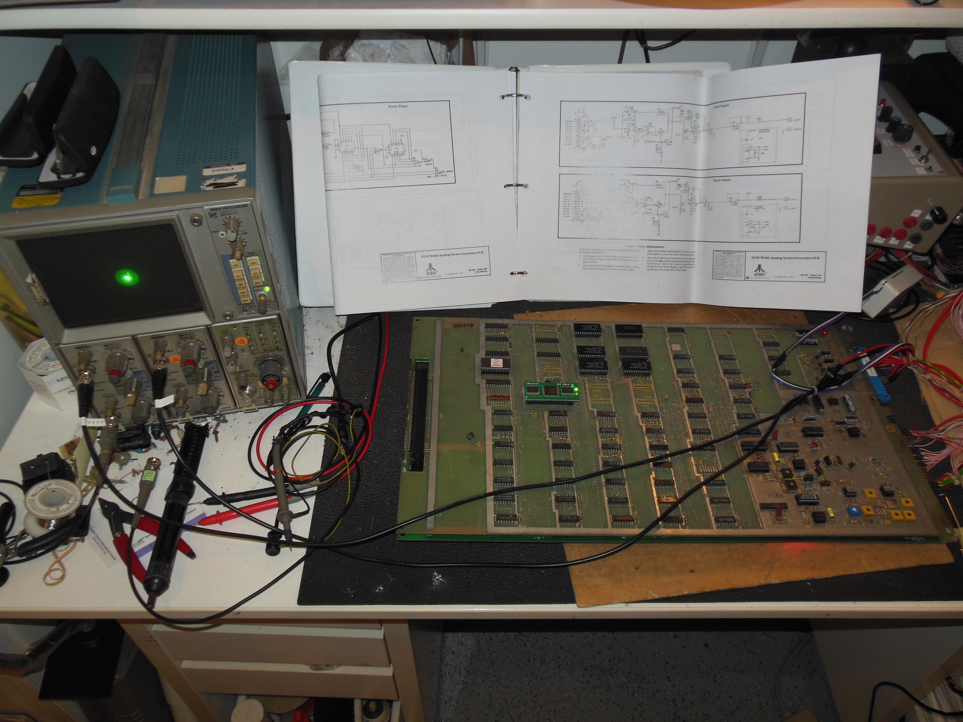
A quick verification with the Arduino ICT confirmed that the AVG ROM and RAM tested OK.
Running in test mode there was no vector output at all on either X or Y. IC 6AB (AM6012)
'DVX' inputs were all idle and IC 6E (AM6012) 'DVY' inputs were active. Tracing the 'DVX' signals
back to IC 5C (LS194) pins 12 to 15 were idle, pin 1 'LATCH1' active, and pin 11
'12MHZ' active. Input pins 3 to 6 were active, pin 9 'S0' idle low, and pin 10 'S1' active.
Moving back to IC 14D (LS14) found pin 5 'LATCH2' and pin 13 'LATCH3' both idle high with
some clock noise. Mapping state machine output decoder IC 3D (LS42) pins found:
| 1 - Active | 16 - Idle high |
| 2 - Active | 15 - Active |
| 3 - Idle high | 14 - Active |
| 4 - Idle high | 13 - Active |
| 5 - Active | 12 - Active |
| 6 - Active | 11 - Active |
| 7 - Active | 10 - Active |
| 8 - Idle low | 9 - Idle high |
It was difficult to tell if the issue was that the vector RAM instructions were not being
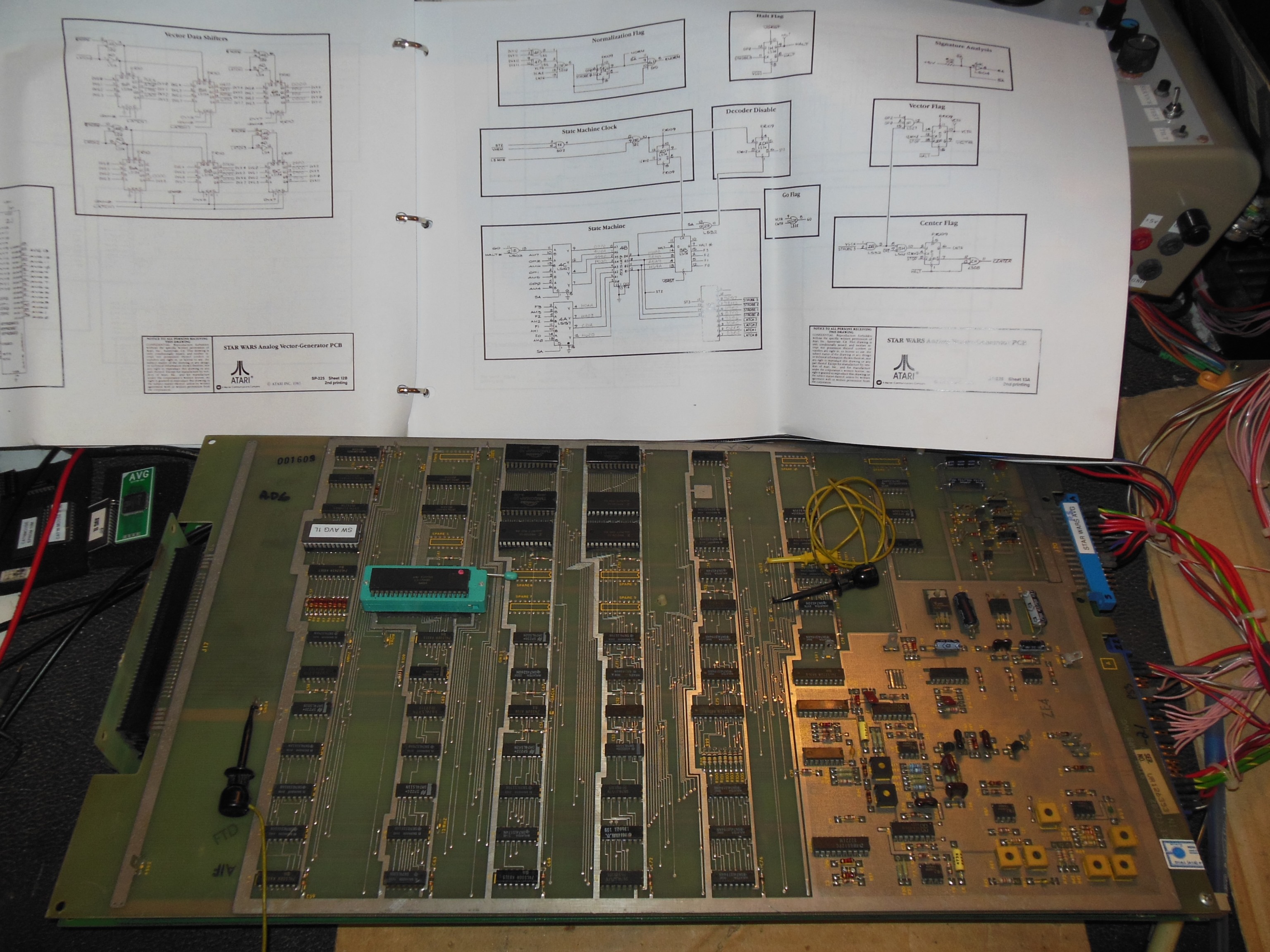
loaded properly or the vector state machine had a problem executing them. Reviewing the
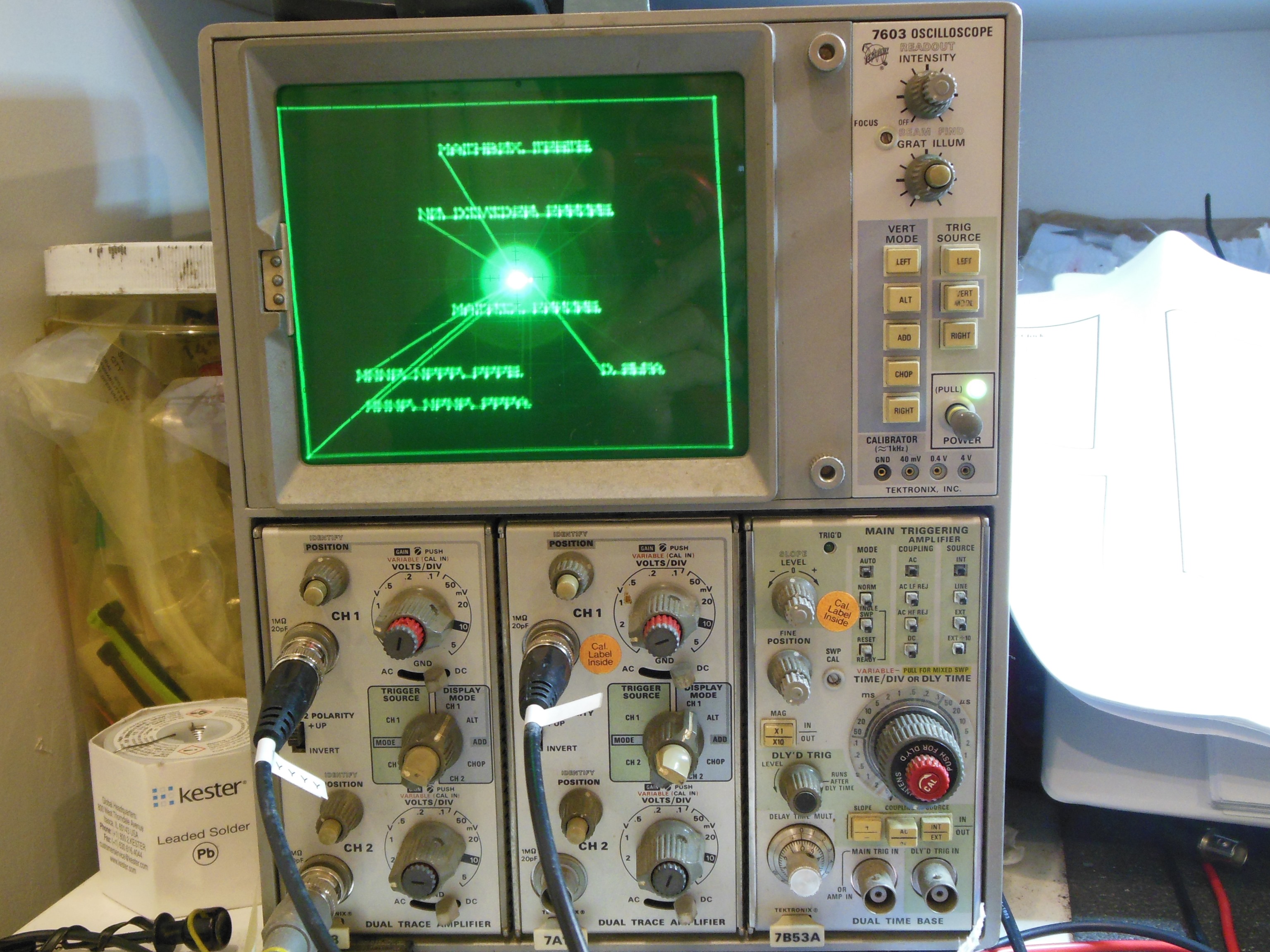
schematics and Star Wars Troubleshooting Guide found that Signature Analysis 'SA' mode would
disconnect the instruction load and replace it with an address counter routed through to the
state machine. The 'SA' test point was tied low and IC 3D (LS42) mapped out again:
| 1 - Clock | 16 - Idle high |
| 2 - Active | 15 - Active |
| 3 - Idle high | 14 - Active |
| 4 - Active | 13 - Active |
| 5 - Active | 12 - Clock |
| 6 - Active | 11 - Active |
| 7 - Active | 10 - Clock |
| 8 - Idle low | 9 - Idle high |
|
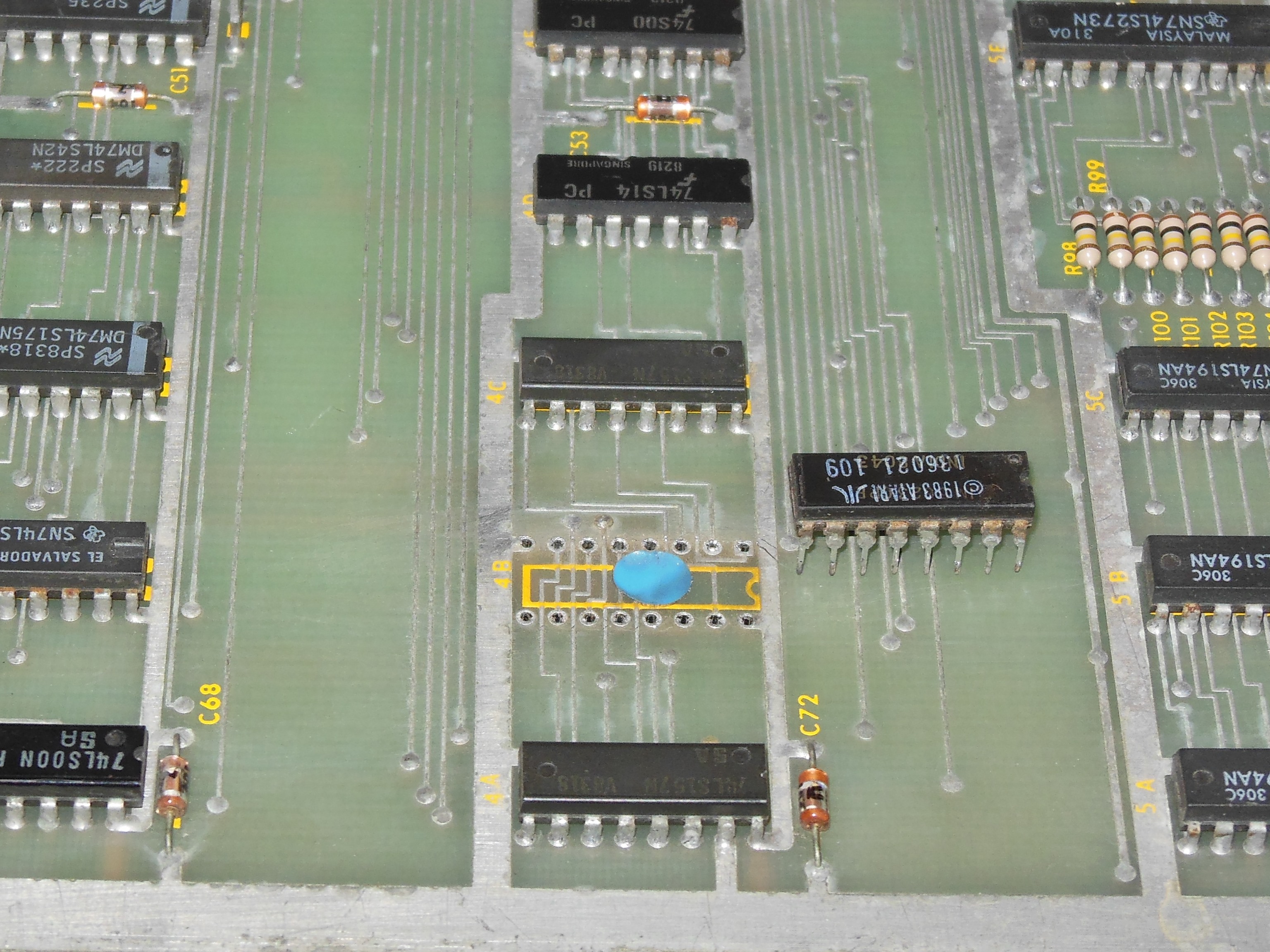
In signature analysis mode pin 4 was now active but pin 3 was still idle. IC 4B (82S129) inputs looked like a counter, but input pins 4 & 5 had overtones as if shorted to another signal. The signal was still within TTL levels, however. In run mode the two inputs still had overtones. Inspecting the schematics for the value of IC 3D pin 3 deduced it was either 0x2 or 0xA output from the state machine PROM. Checking the ROM image found only a single occurrence at address 0x8B containing 0xA and I suspected the state machine PROM was bad.
|
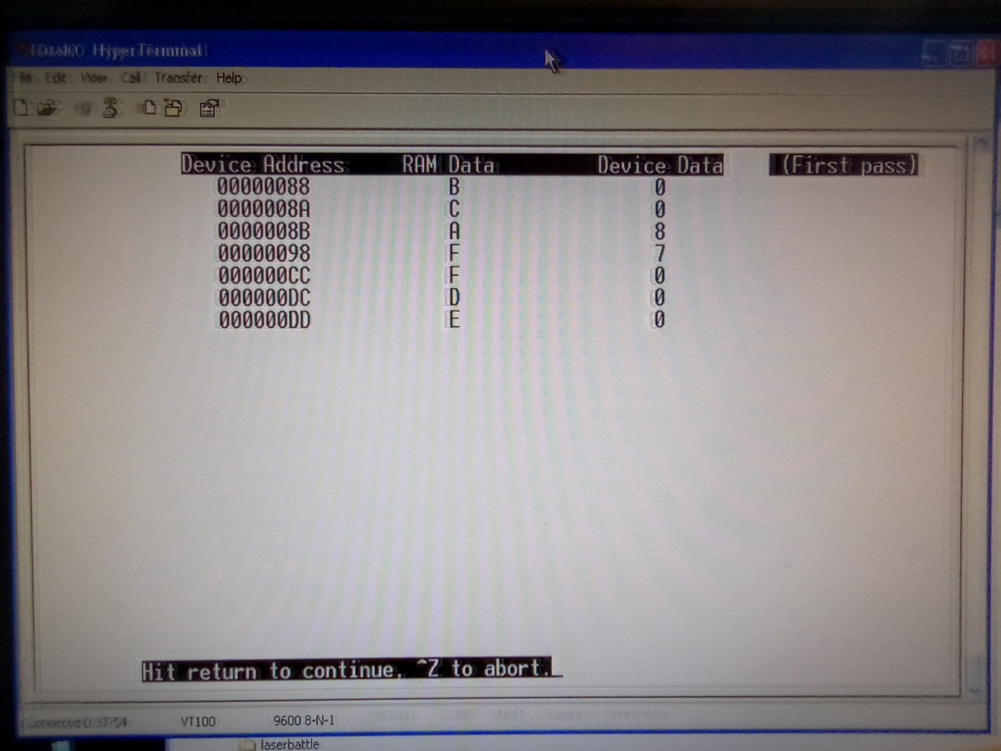
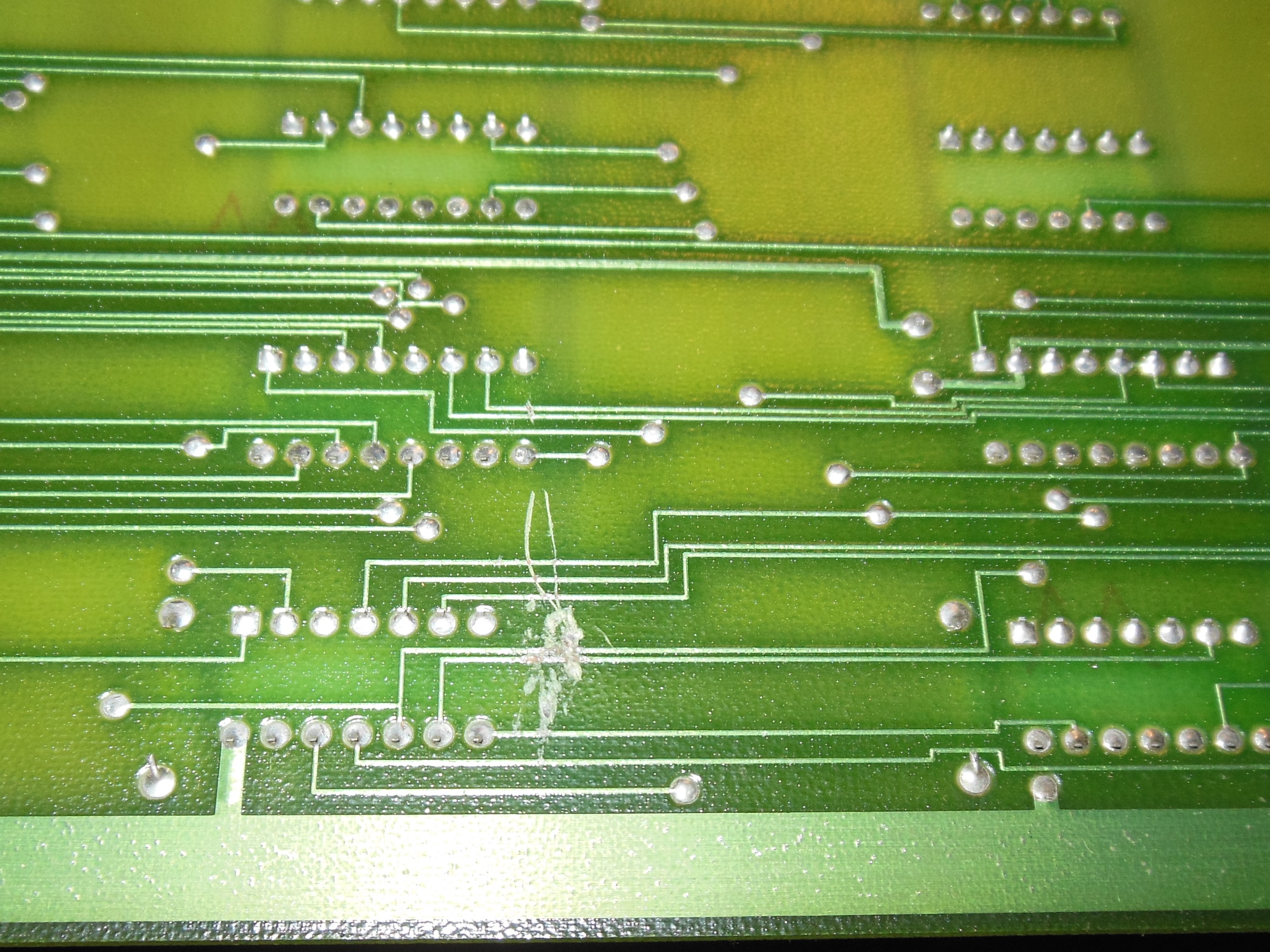
The state machine PROM IC 4B was an 82S129 that was very difficult to source still blank. I had a couple left but wanted to be really sure the PROM was bad before using one, so in this case the PROM was desoldered intact also revealing a small dot sticker underneath. With IC 4B removed input pins 1 to 7 all looked good - the overtone was gone. Verifying the removed PROM in the DataIO UniSite confirmed that 7 nibbles were bad and one of the bad nibbles was address 0x8B. A replacement 82S129 state machine PROM was programmed that fixed the board and the game ran OK on the bench.
|
I had one more complete set of Star Wars game PCBs. The sound PCB and all its ICs was heavily corroded (a.k.a. "raised from the Titanic"). The main PCB had a very large number of blown ICs (a.k.a. "lightning strike"). The AVG PCB was in good physical condition, better than the slightly corroded spare I was already running. It was marked "dead" and I decided to attempt to repair it as a third working AVG board.
Starting with the Arduino ICT, the ROM check failed "E:1L 3001 ec bc" confirming the "bad" written on IC 1L (2732) EPROM. RAM check failures also matched the "bad" written on ICs 3L,4L,4M (TMM2016-10). A set of MB8128-10 was used to replace the three RAMs and a newly programmed HM482732AG-20 replaced the IC 1L EPROM. All ROM & RAM checks now passed.
|
Assembled and in test mode X,Y,Z were mostly idle. The AVG bus was mostly idle and IC 3D (LS42) outputs were mostly idle. In Signature Analysis 'SA' mode:
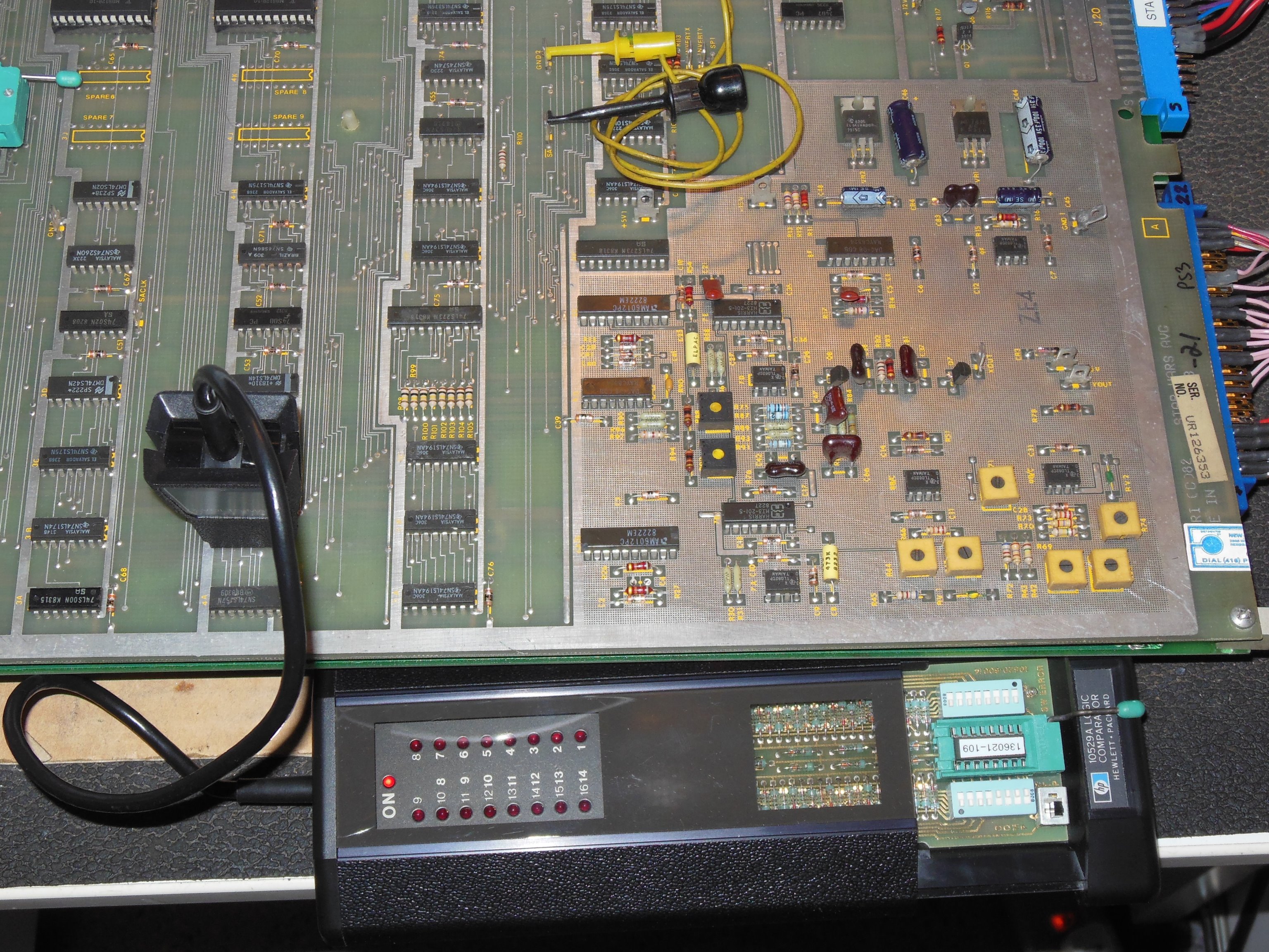
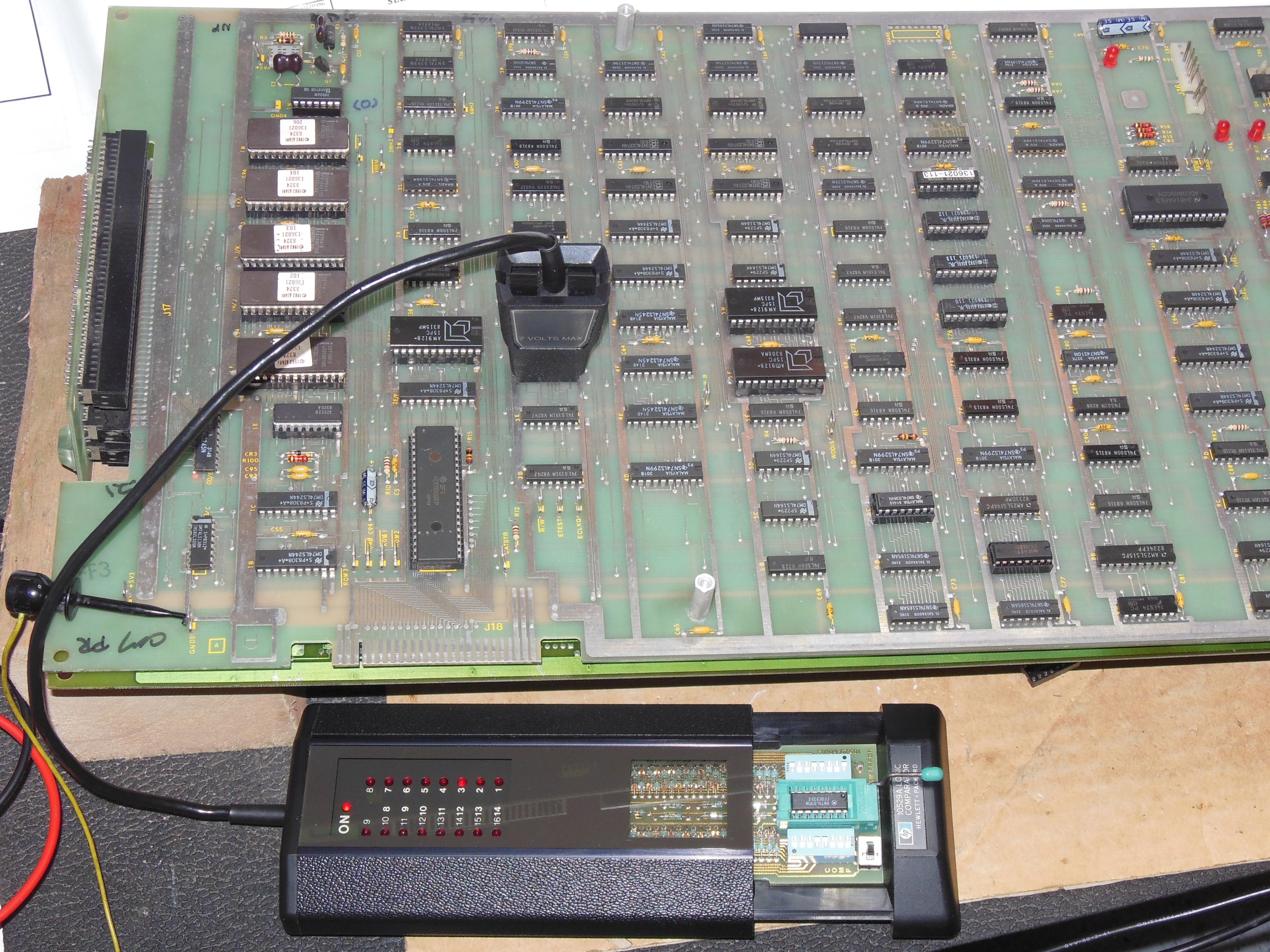
I had recently programmed a new state machine PROM 4B (82S129) and noticed that it was compatible with the HP Comparator. An in-circuit compare of IC 4B passed OK. In SA mode an in-circuit compare of ICs 5F,5H,6H,5A,5B,5C (LS194) also passed OK. I wasn't really getting very far so I decided to add support for testing the AVG vector instruction set.
Back on the Arduino ICT, two new RAM failures were flagged - "E:3M 0800 91 0f" and "E:4P 2800 91 ff". These two along with the last remining original TMM2016 were replaced. Testing the 'VCTR' command found that VGGO was clearing HALT but HALT was never being set again. VGRST was setting HALT, however. Testing the HALT instruction also suggested HALT was working. The Arduino ICT program was updated to also support signal capture with the AVG tests.
Signal capture was setup with the following sequence:
|
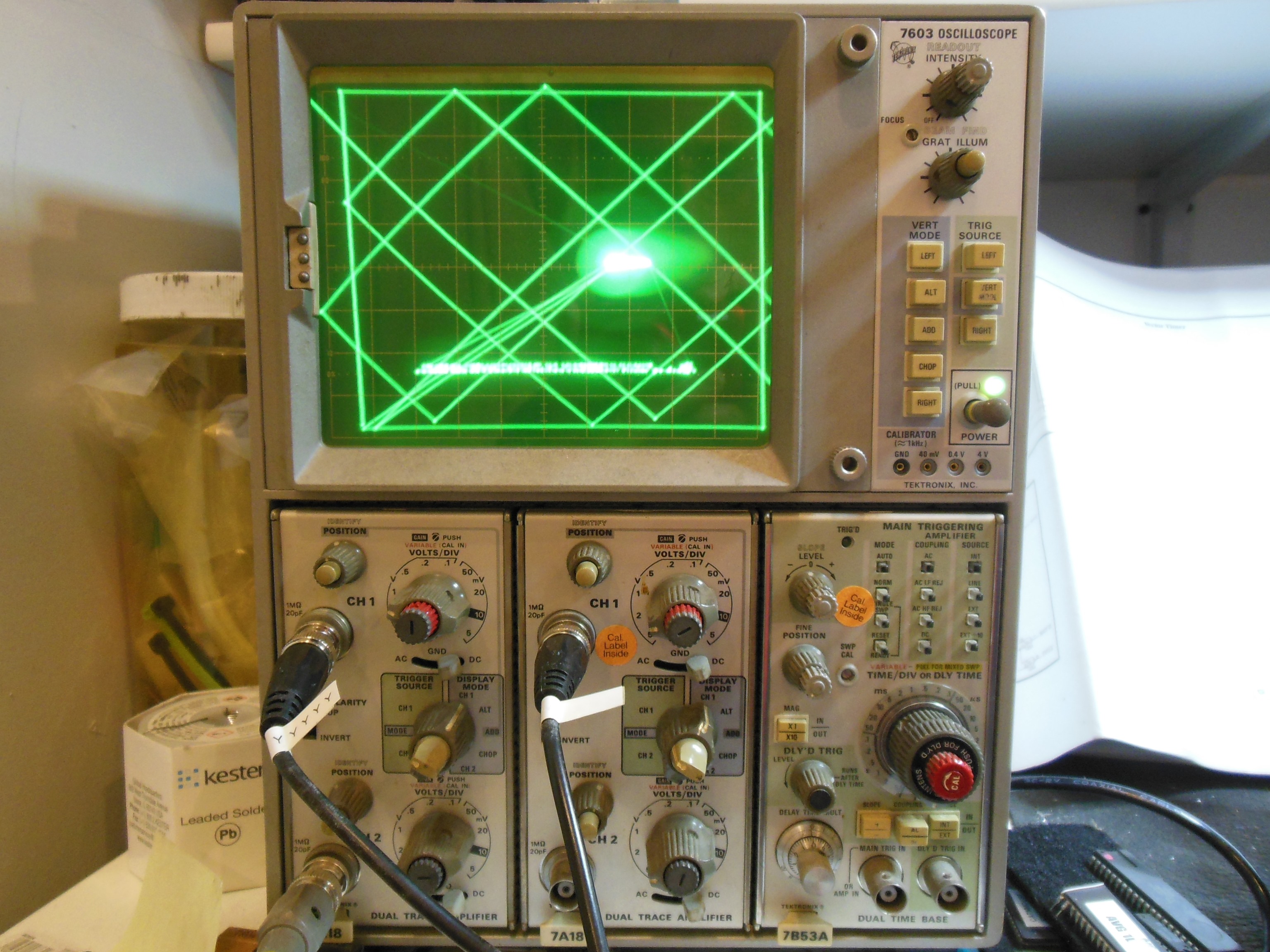
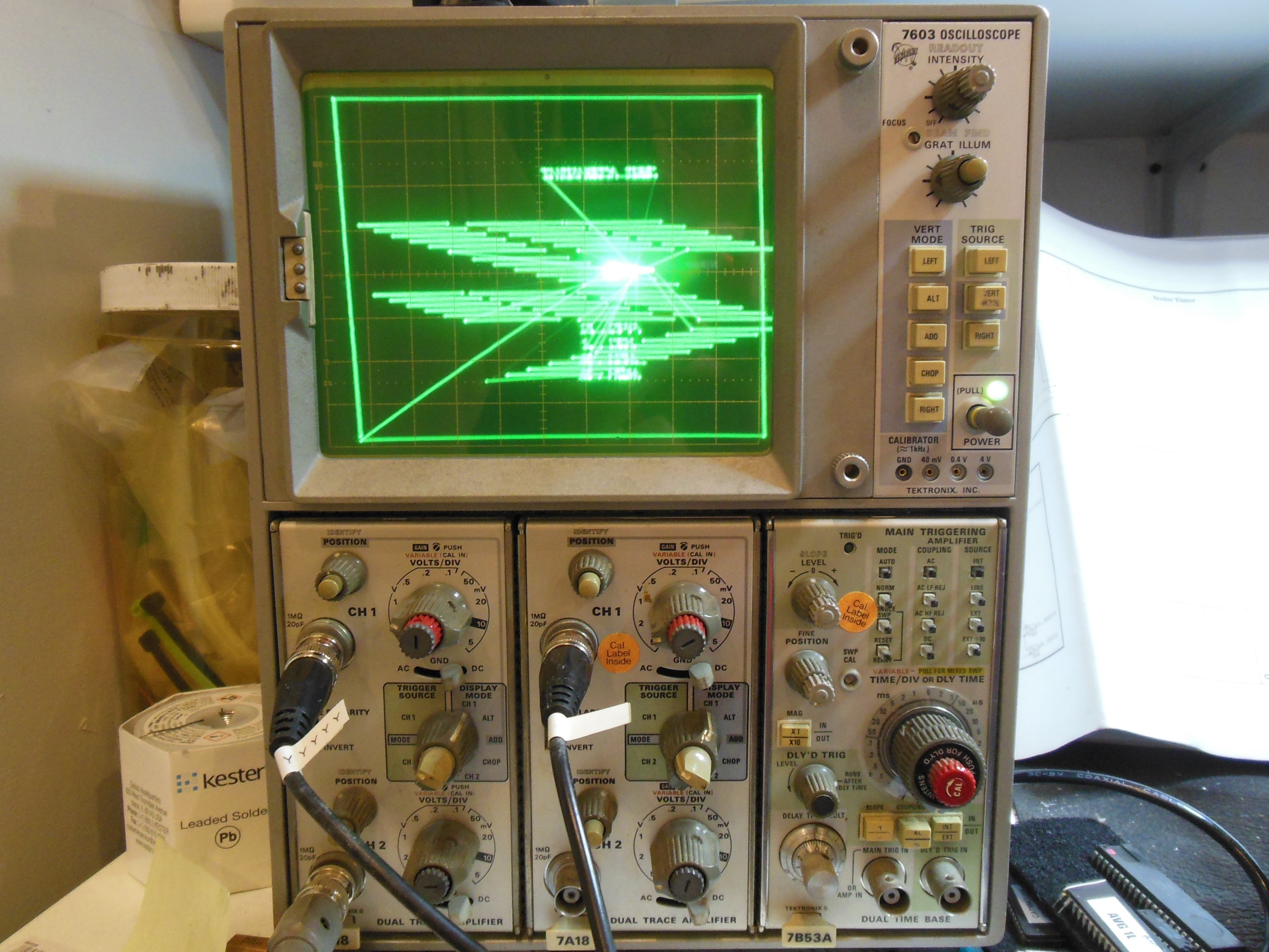
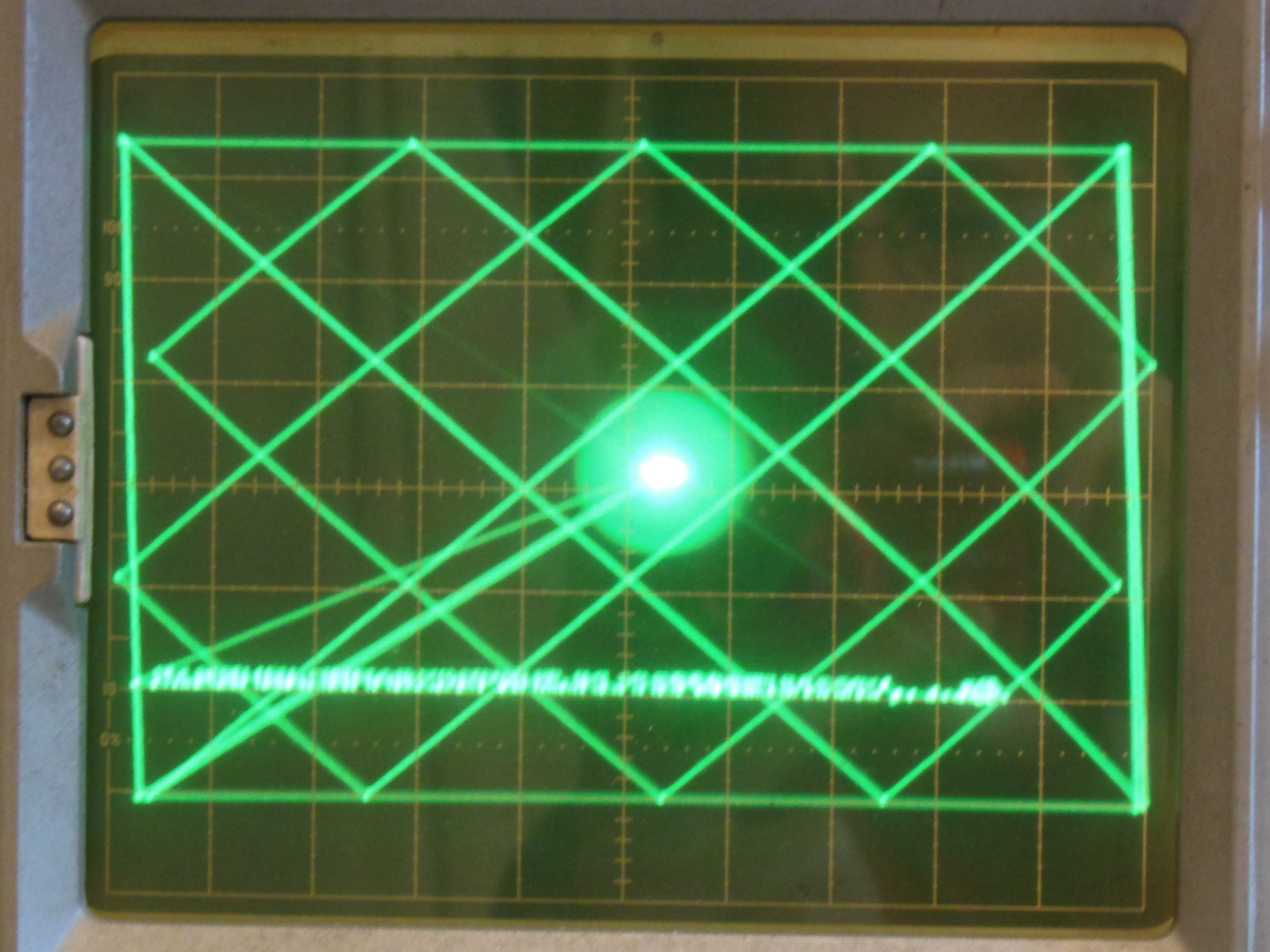
In test mode the display was now running but still had some alignment issues in the cross hatch test, with 'X' being slightly off.
|
Back with the Arduino ICT and the 0x55/0xAA pattern test, IC 6AB DVX3 to DVX12 were all switching OK. The full swing of XOUT and YOUT to +/- 15V was also OK. Comparing IC 6AB pin 14 XREF was a 2V AC sine wave whereas IC 6E pin 14 YREF was 0V. Capacitor C4 (0.01uF) was missing that connected XREF to VR-. Fitting the missing capacitor fixed the test mode alignment and the game mode display had no issues. The AVG PCB was declared fixed.
|
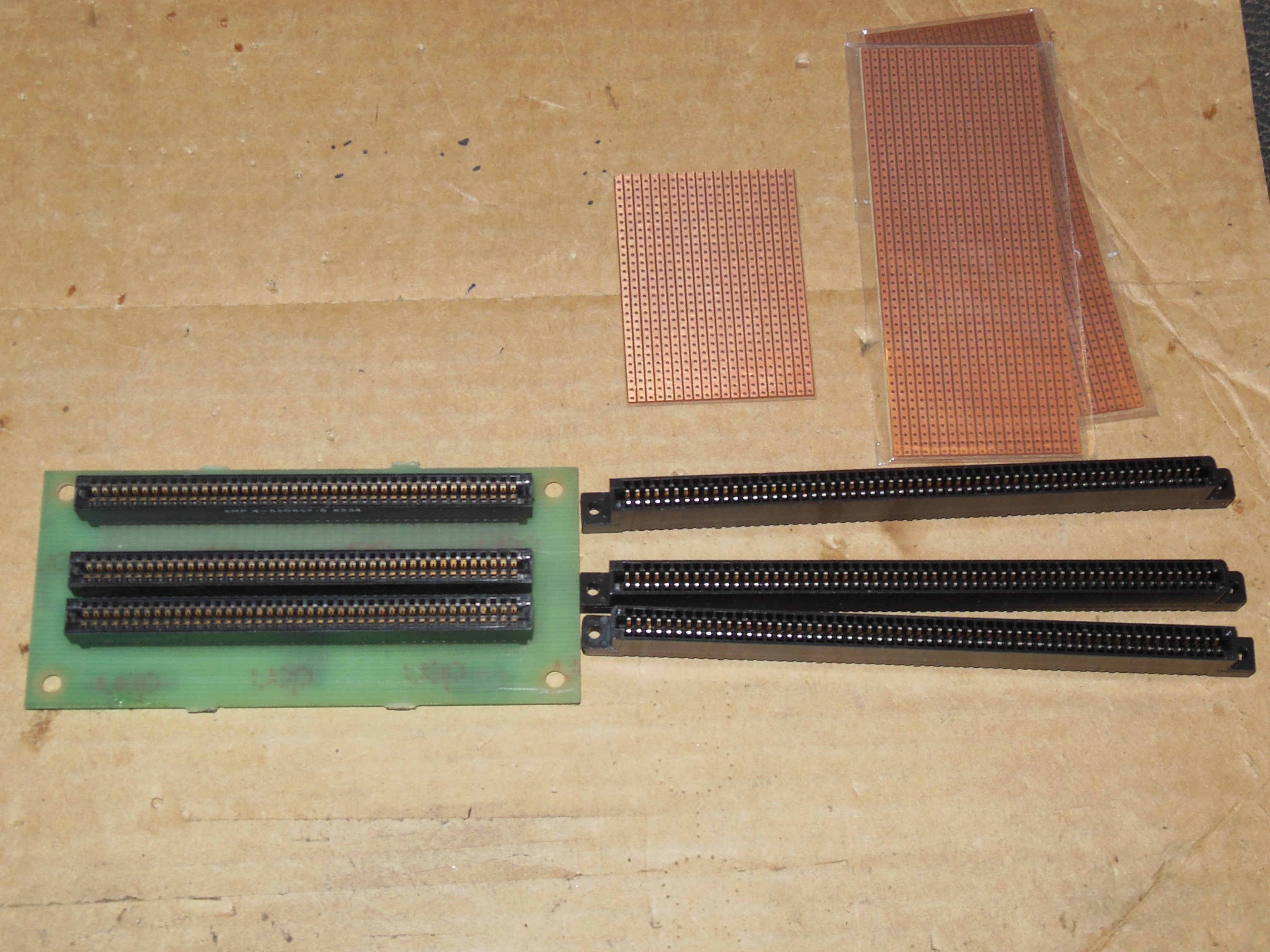
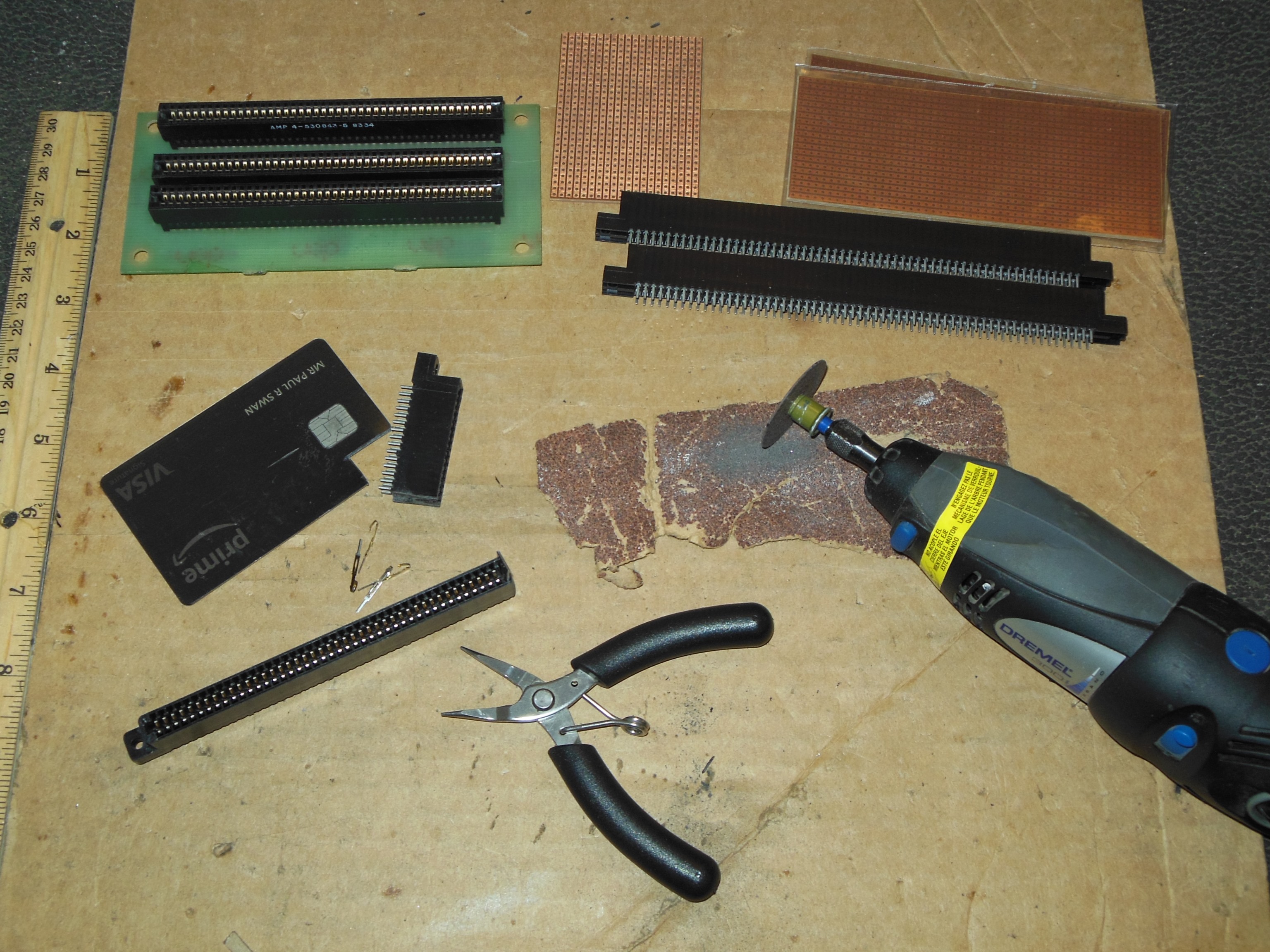
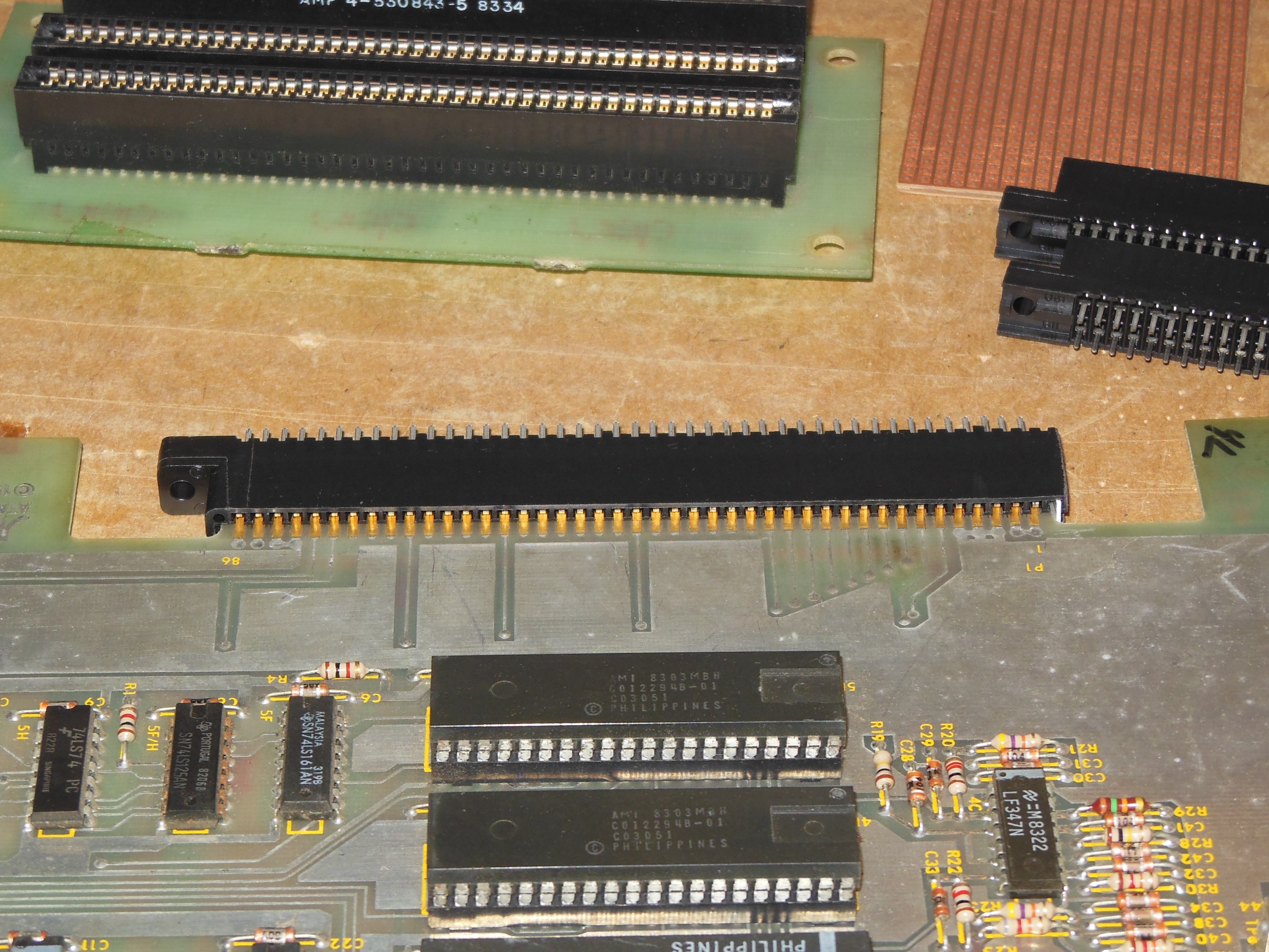
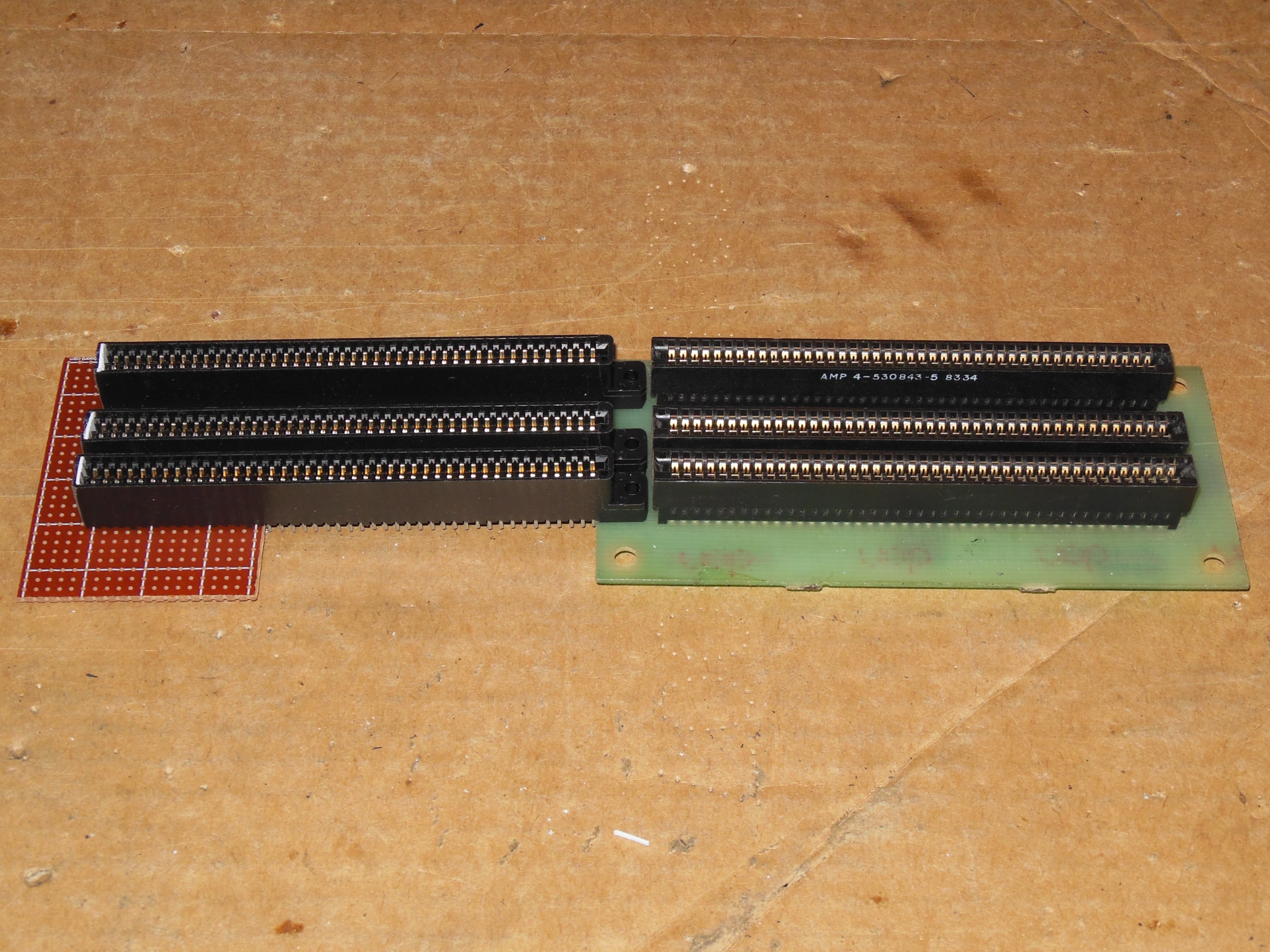
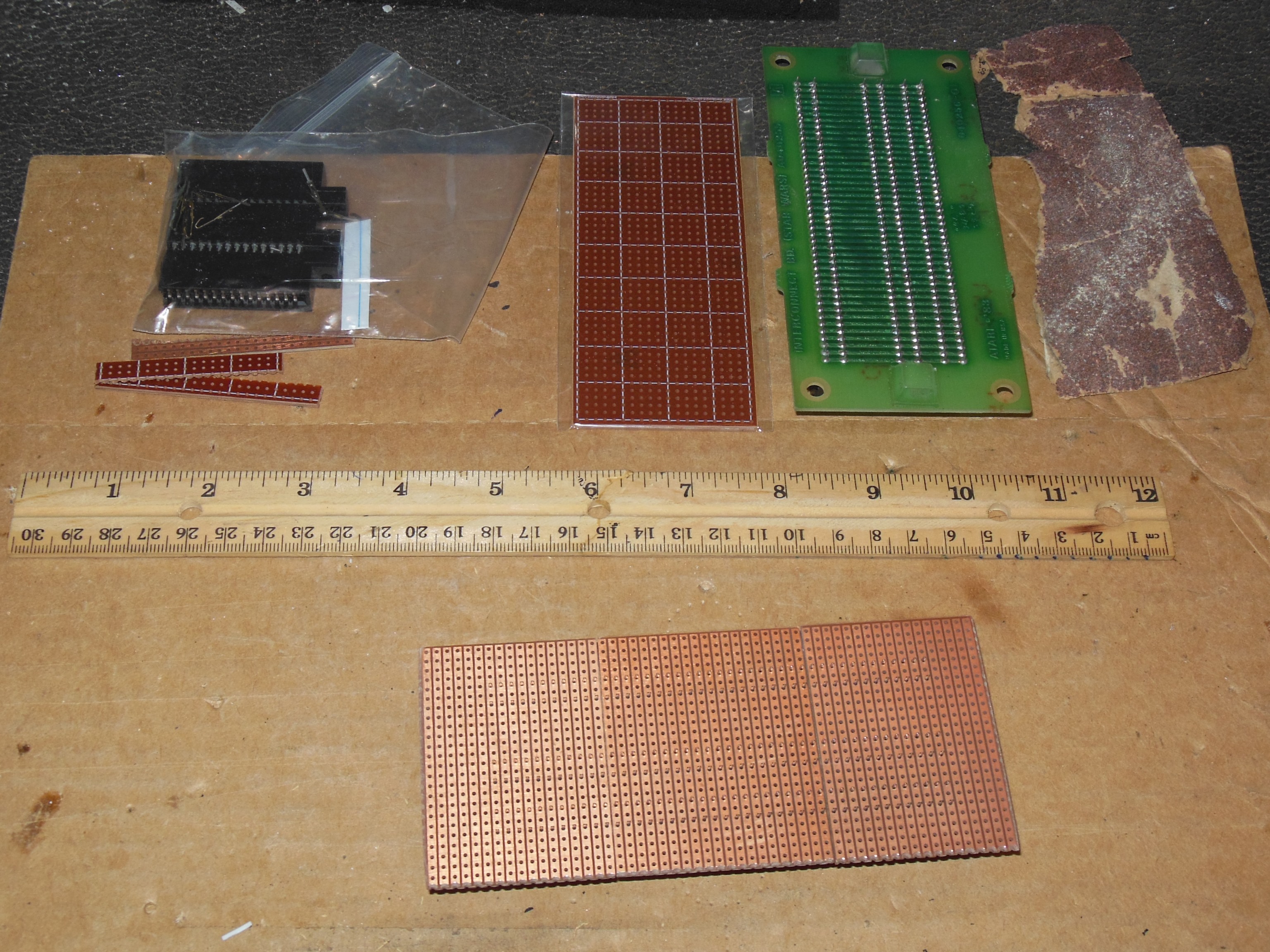
Though I had two complete working Star Wars game PCB sets I had only one interconnect PCB, making repair work awkward and putting a lot of wear on the edge connectors. Inspection of the interconnect PCB confirmed it was very simple 0.1" pitch through tracked and could be made from Veroboard stripboard. The exact size edge connectors are hard to find, but any larger connector could be cut down to fit using a key piece. Three Cinch 0.1" 120-contact connectors from eBay were cut down to 86-contacts and key pieces made from an old credit card.
|
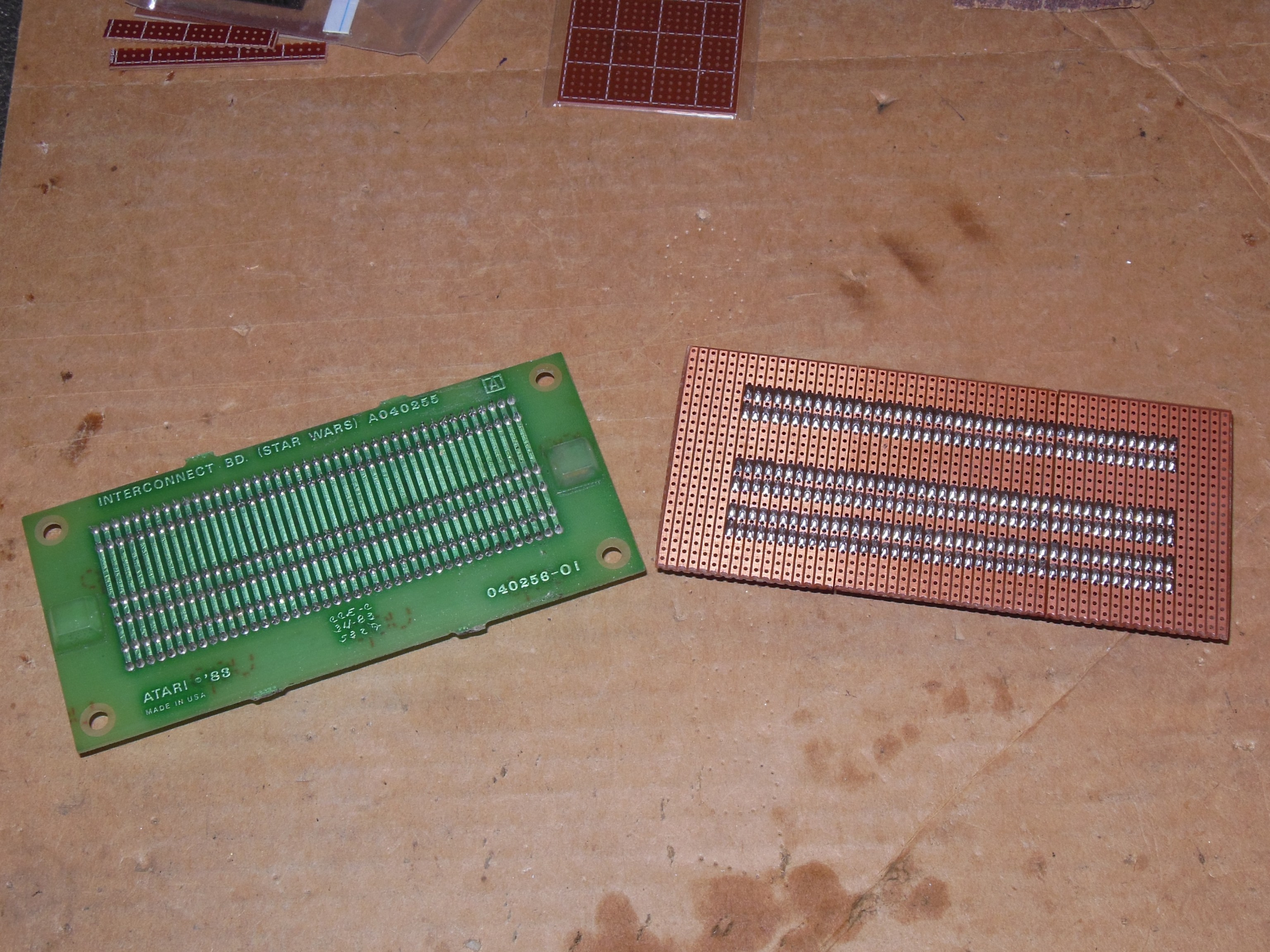
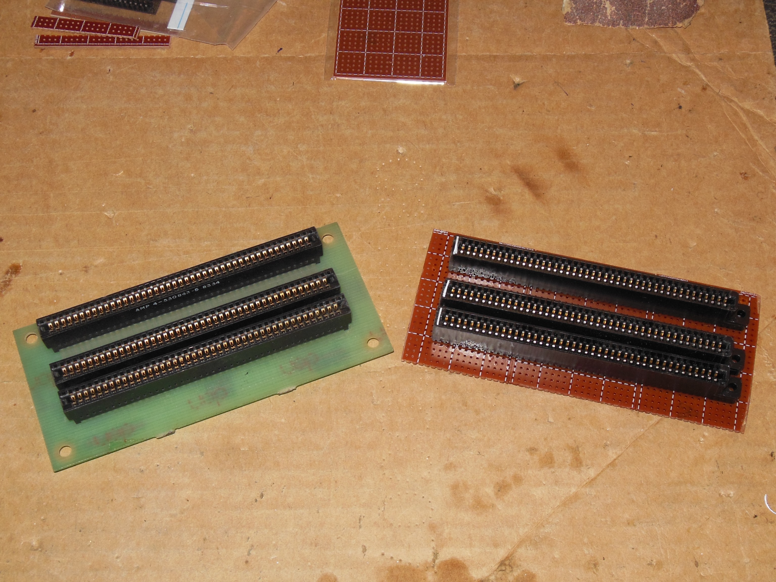
Three pieces of Veroboard stripboard were needed to complete the whole of the connector. The pieces were cut down to match the original PCB size and edges sanded down to fit together. All the parts were assembled and aligned with the spacing of the original PCB. The 0.1" pitch was good enough for a close match to the original inter-board spacing of the PCB stack.
|
All the connectors were soldered, completing the interconnect. Testing with a PCB set confirmed the new interconnect was working OK.
|
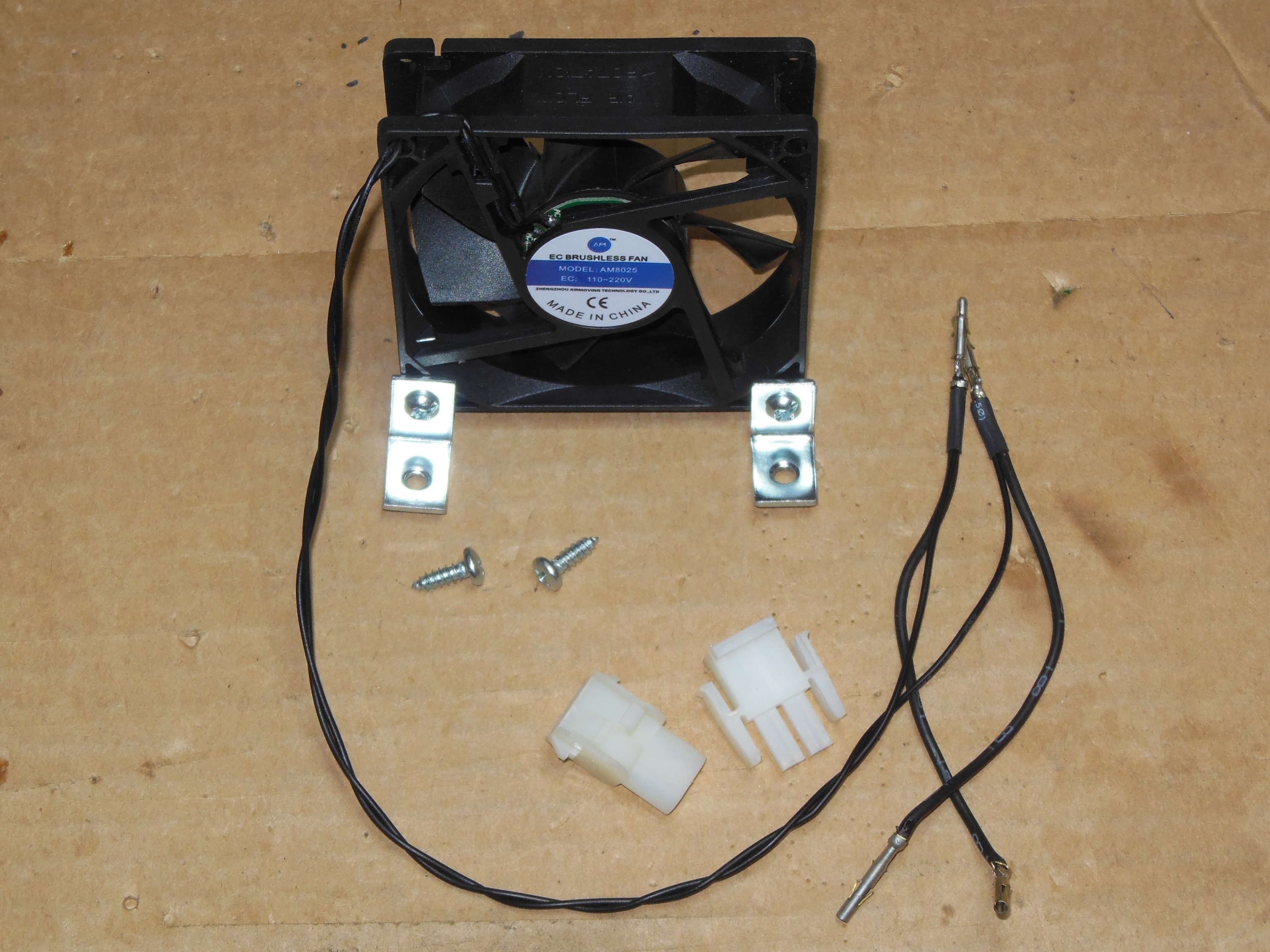
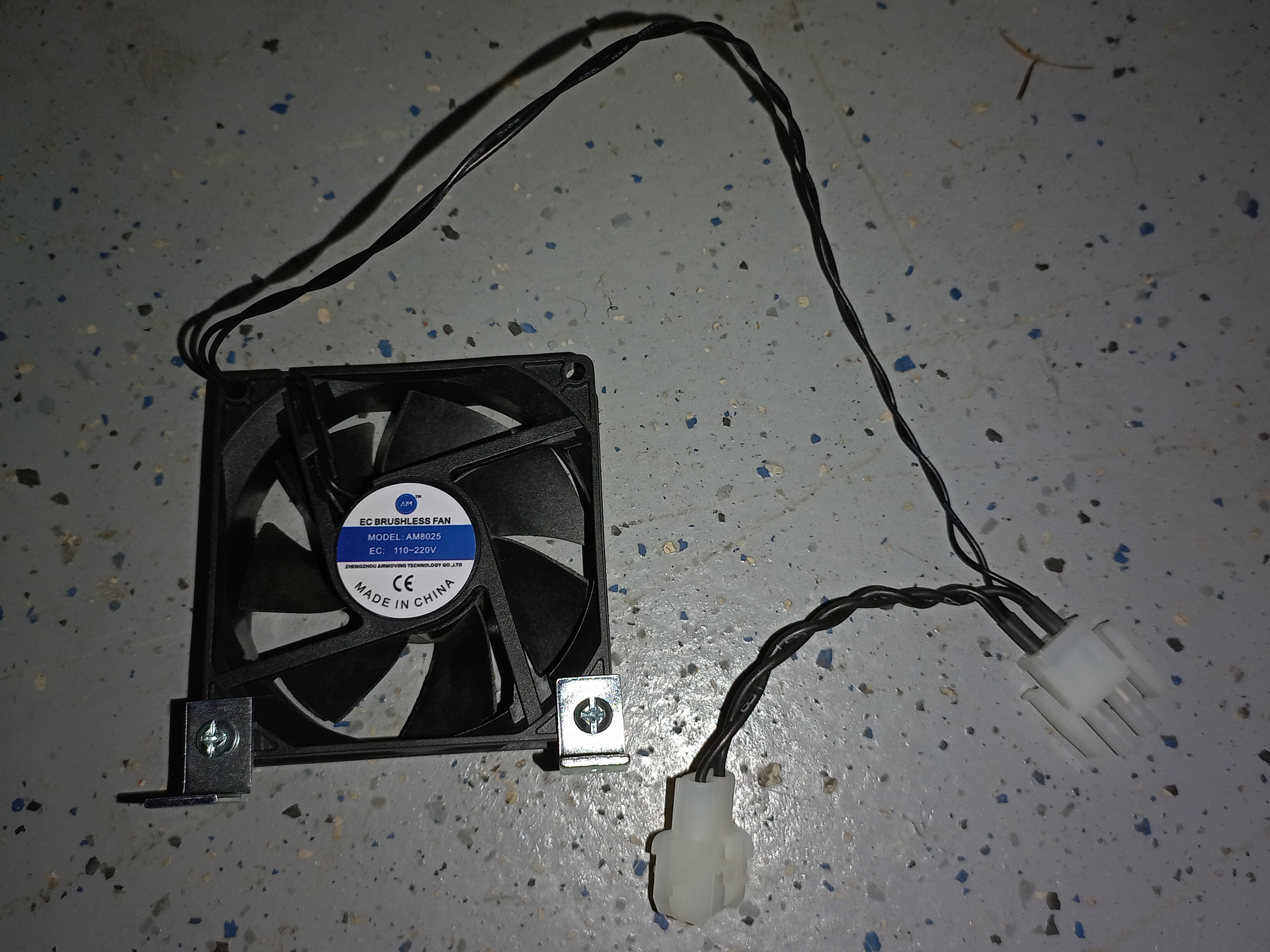
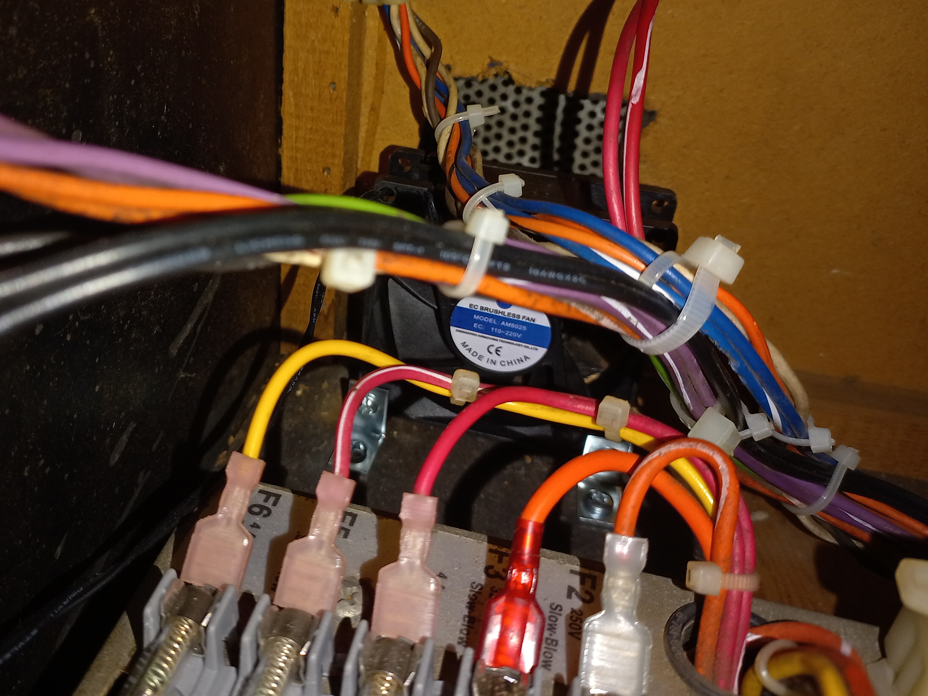
There were already four small internal fans, two on the game PCB, one on the Amplifone HV and one on the deflection PCB. Whilst these had worked well keeping the monitor working reliably over the years, the game PCBs had still had reliability challenges and I'd noticed that the inside of the small cockpit cabinet space still eventually got hot after several hours. There was already grill covered hole in the bottom, left over from the Konami GT pedal, that I decided to add an 80mm inlet fan to draw in outside cool air near the game PCBs. An inline connector pair was built to tap 110V power from the utility power outlet inside the cabinet and the fan was mounted near the hole on small brackets. Testing the cabinet confirmed inlet air flow in the vicinity of the power brick, ARII and game PCBs. Maybe it would make a difference, maybe it wouldn't.
|
Back in the cabinet, one game PCB set still had vector issues in game play. Test mode reported all hardware self-tests passing and the display tests all looked OK. I did also notice that the DIP switch test showed intermittent state. The game PCB was removed for repair.
|
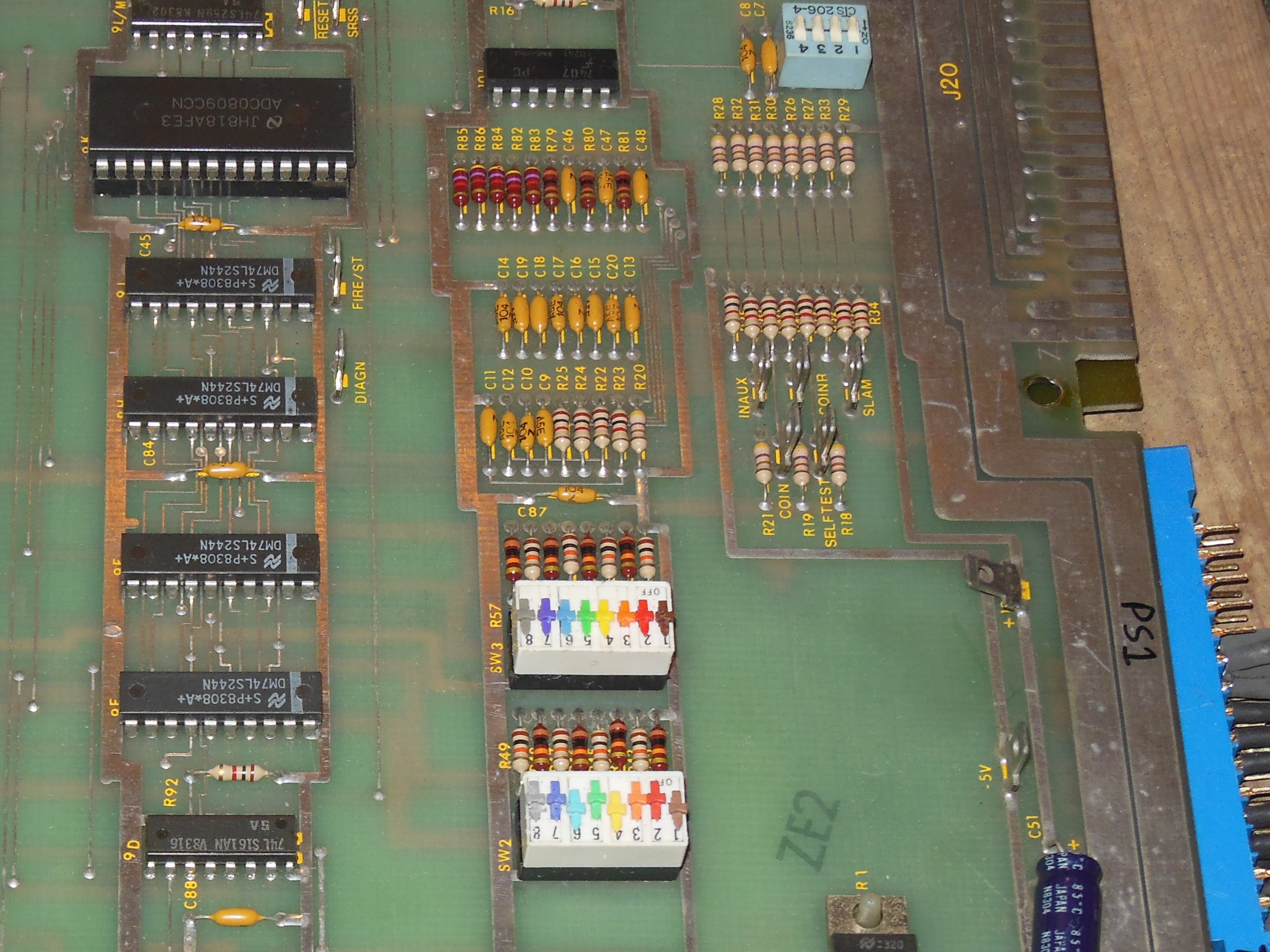
On the bench, the DIP switch intermittency was quickly confirmed as bad DIP switches - running a finger across them caused the reported value in test mode to change on both SW1 and SW2. Both DIP switches were replaced that fixed the intermittency.
|
The vectors looked OK on the bench, and I suspected a power supply voltage dependency.
Adjusting the AR II to lower the +5V resulted in the vector issue occurring. Swapping in the
spare AVG PCB confirmed that the issue was related to the main PCB, but all the math
box tests passed. I still suspected a problem with the matrix processor based on much
of the Matrix Processor Address Counter and Block Index Counter not being exercised in
the self-test. Given the correlation with power supply voltage, the signal levels on
ICs 3H (LS157), 3F, 3E, 6H, 6J (LS191) were checked on the scope for valid TTL levels that
all looked OK.
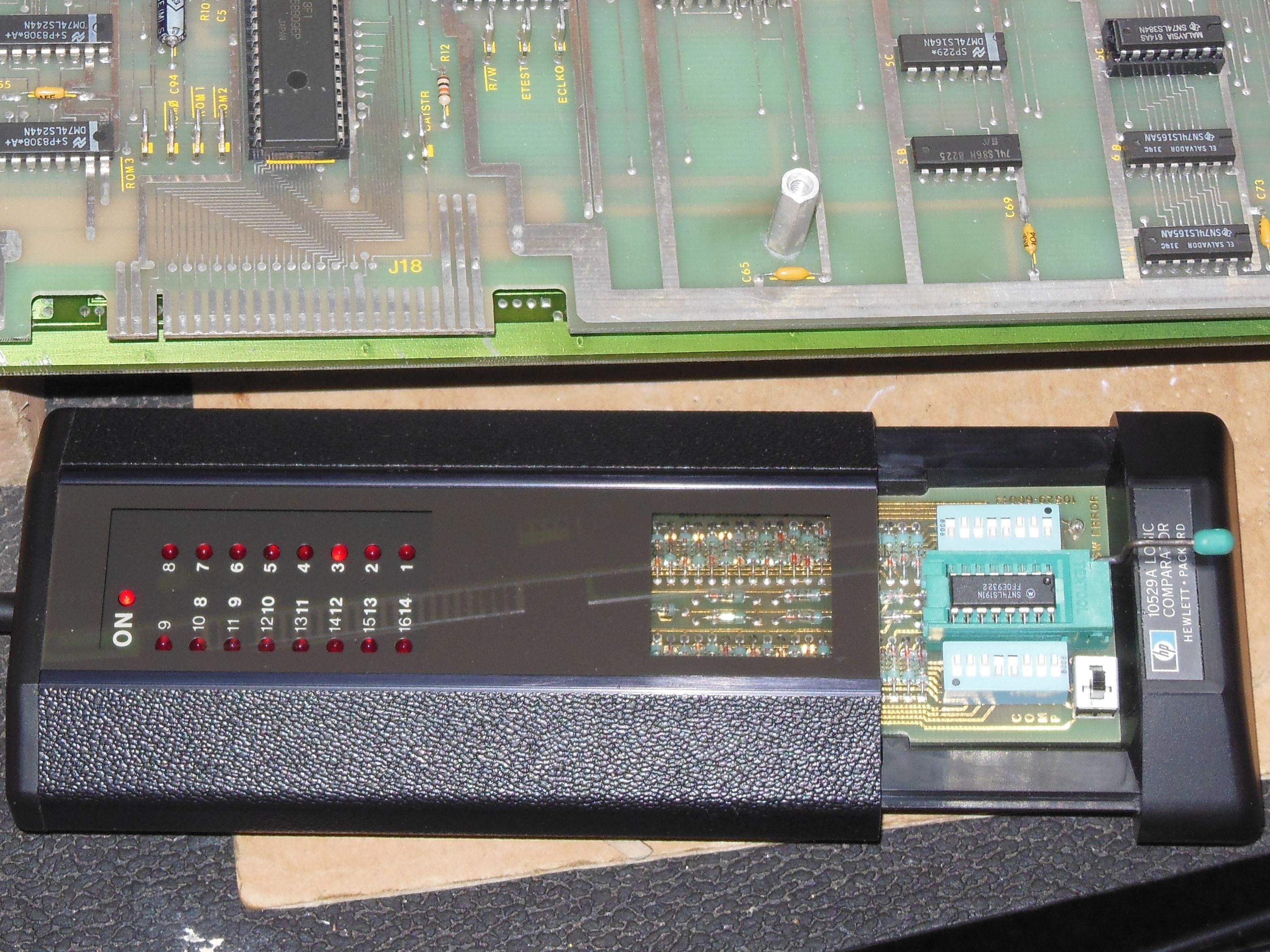
Setting up the HP comparator for 74LS191 found:
On retest the vectors still had issues but the compare of IC 3F was now passing. I caught an occasional flash of compare failure on pin 3 still, and confirmed that a slightly lower power supply voltage (now at 4.40V) resulted in compare failure again. Whilst poking around with a scope, a scope lead on pin 14 'INCBIC' caused the compare to clear, and I began to suspect a marginal input signal level or timing somewhere upstream. IC 7E (LS00) pin 4 'WP' with scope leaded caused miss-compare and looked potentially marginal at ~2V high. IC 8E (74S02) pin 10 output looked potentially marginal.
At this point I speculatively considered a marginal timing problem with the matrix RAM IC 5F & 5H. Replacing both AM9128-15 with TMM2016-10 fixed the vectors. Further, neither of the AM9128 worked correctly in location 5F but both worked in 5H suggesting there was something marginal on the upper half of the matrix data bus. Tracing 'BIC4' to 'DB4' followed through to IC 4F (LS245) pin 15 <-> pin 5 'MDB12' <-> IC 5F pin 14 so the compare issue did have a path to the same half of the matrix RAM bus. Checked the scope, IC 5F with AM9128 showed two logic high level lines - one at ~3.8V and the other at ~4.5V. IC 5H had a single ~3.8V logic high. Some swapping confirmed that both AM and TMM RAM in location 5H resulted in a consistent high level whereas in 5F TMM RAM showed consistent high but AM RAM showed the split high. Both levels were still valid TTL high, and I couldn't determine any definitive problem as a result of the TTL high behaviour difference. I suspected there was a bus loading fault somewhere that was going to be very hard to find. With the TMM RAM the game appeared to run without issue across the full range of power supply voltages and was declared fixed.