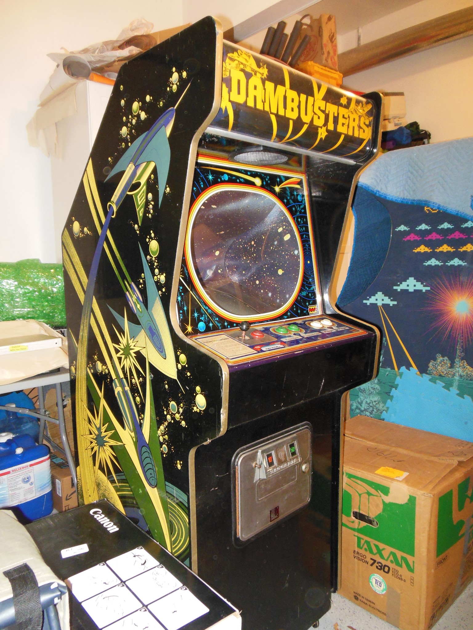

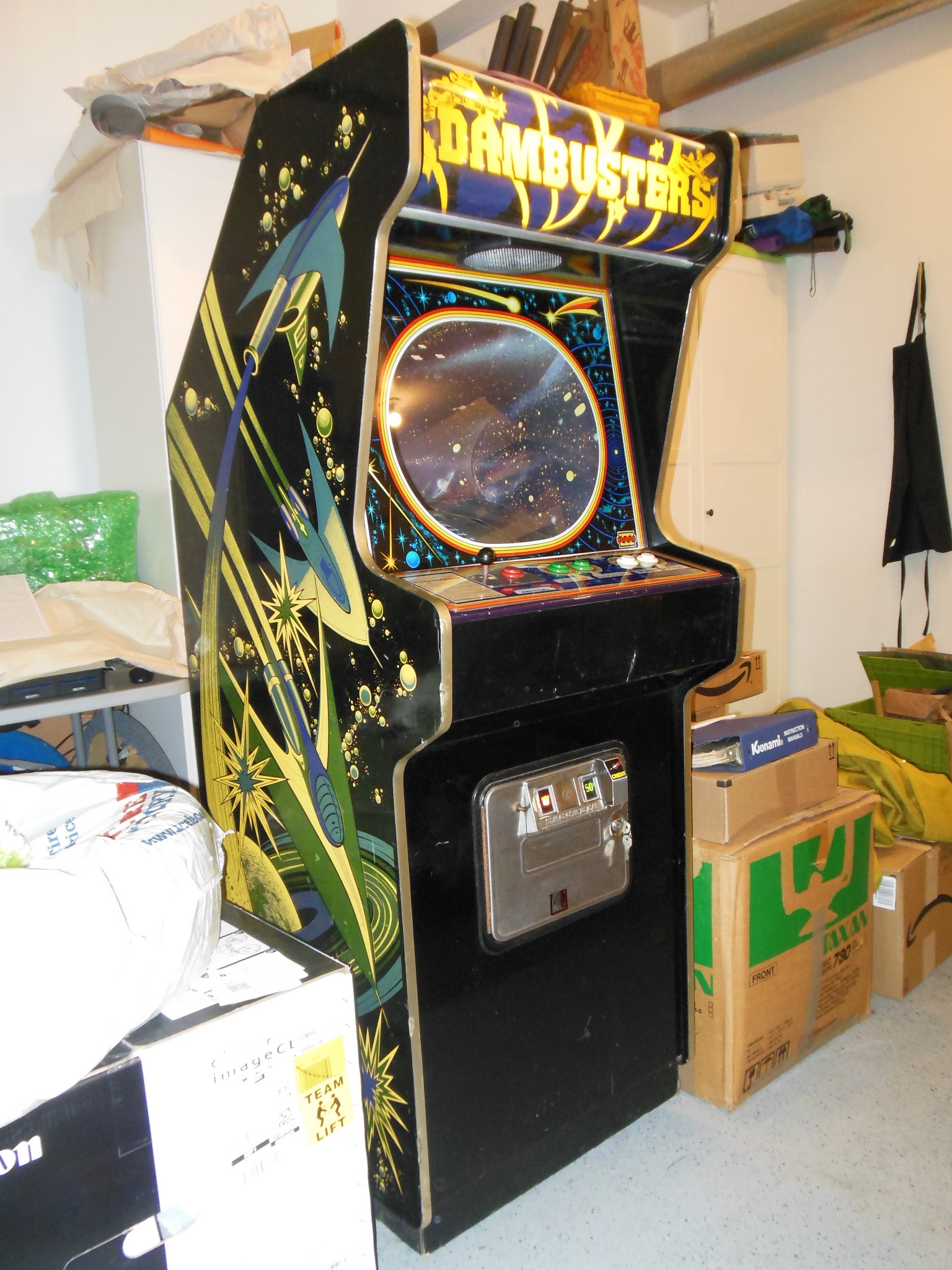
This game is a conversion applied to a Zaccaria Quasar upright. My first encounter with it was as a repair request from a contact in Suffolk. At the time of the repair the owner didn't want to sell it, the board fault was repaired and the game returned to the owner. Sometime later the owner decided to part with it and I bought it from my contact (I never met the owner of the game, my contact mentioned it was originally located around the side of the owners pool). Since I already have both US Billiards and Zaccaria Quasar uprights, the conversion is reasonably neat and Dambusters is an unusual original UK game by South West Research I decided to restore this game as converted to remain as Dambusters.
|
|
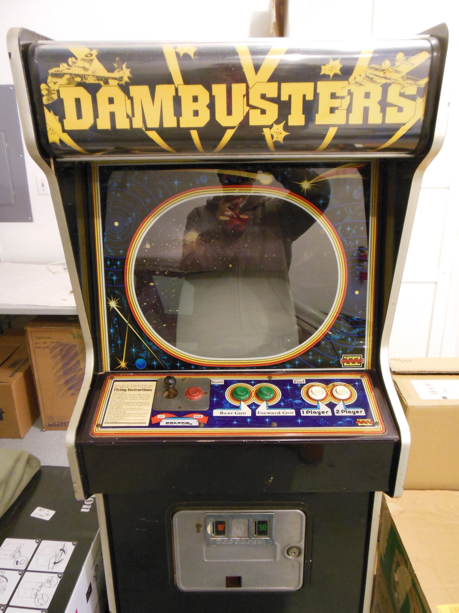
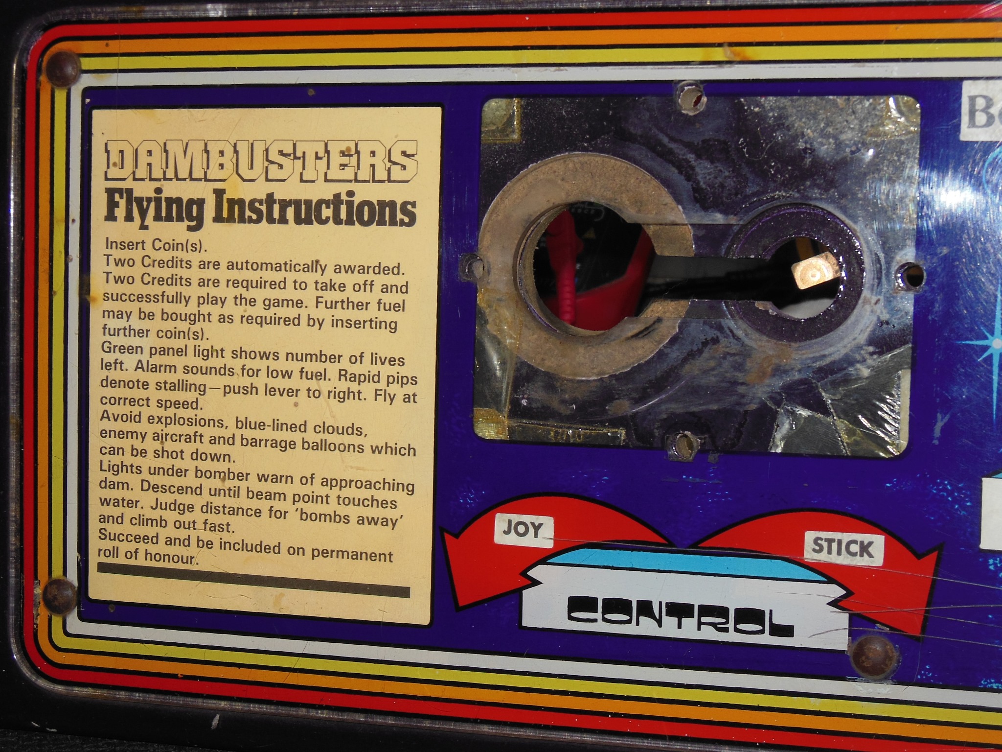
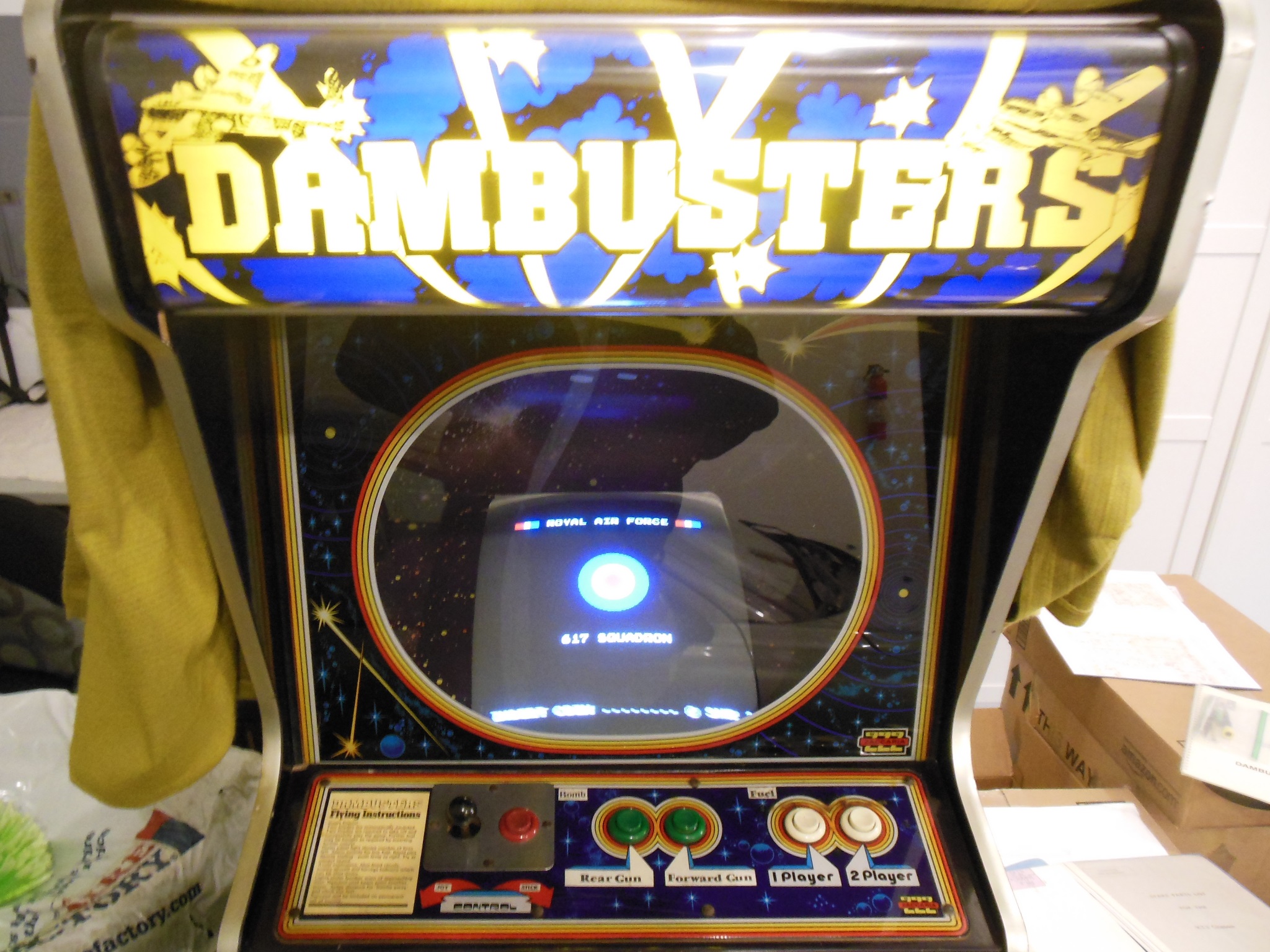
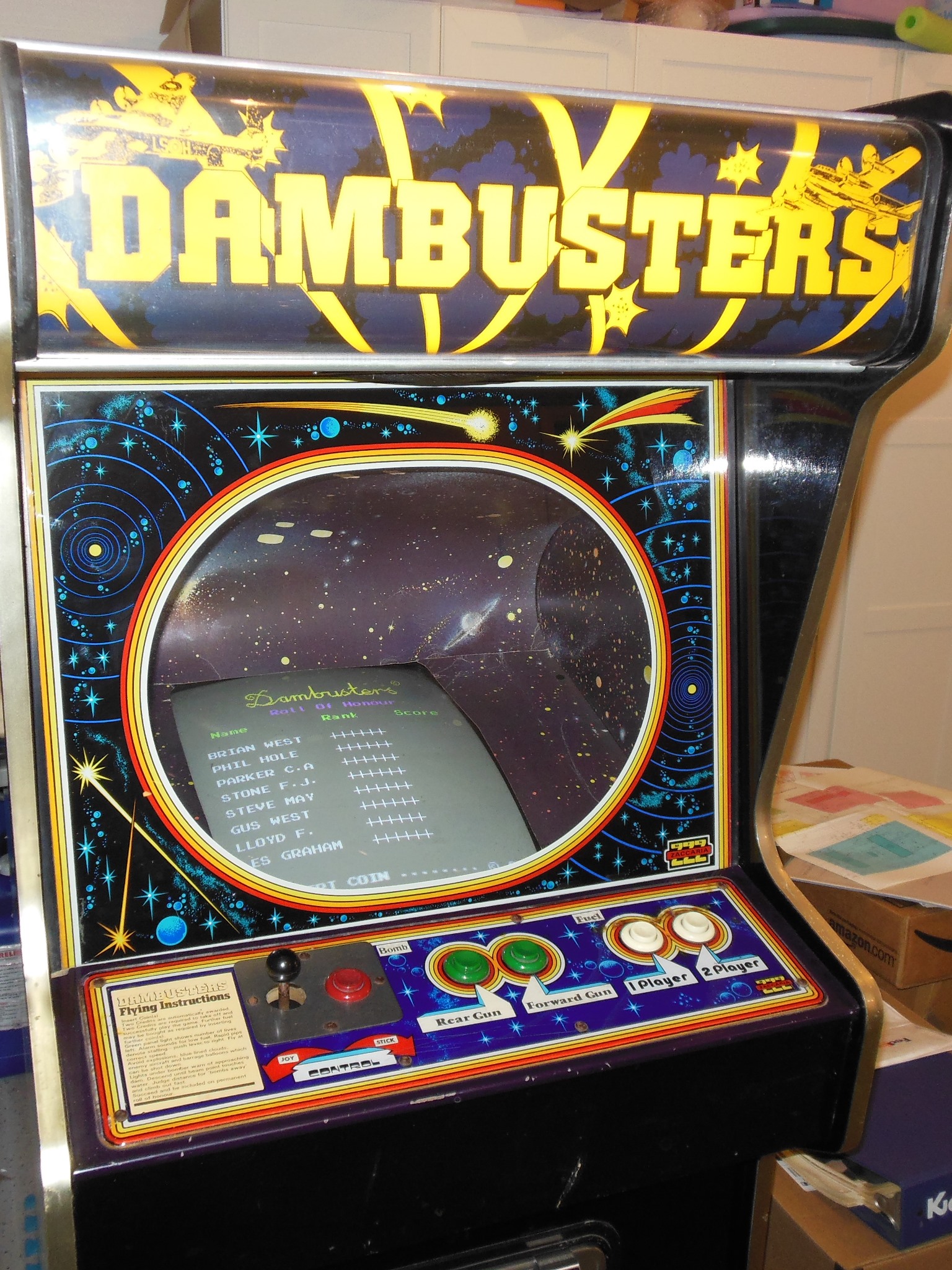
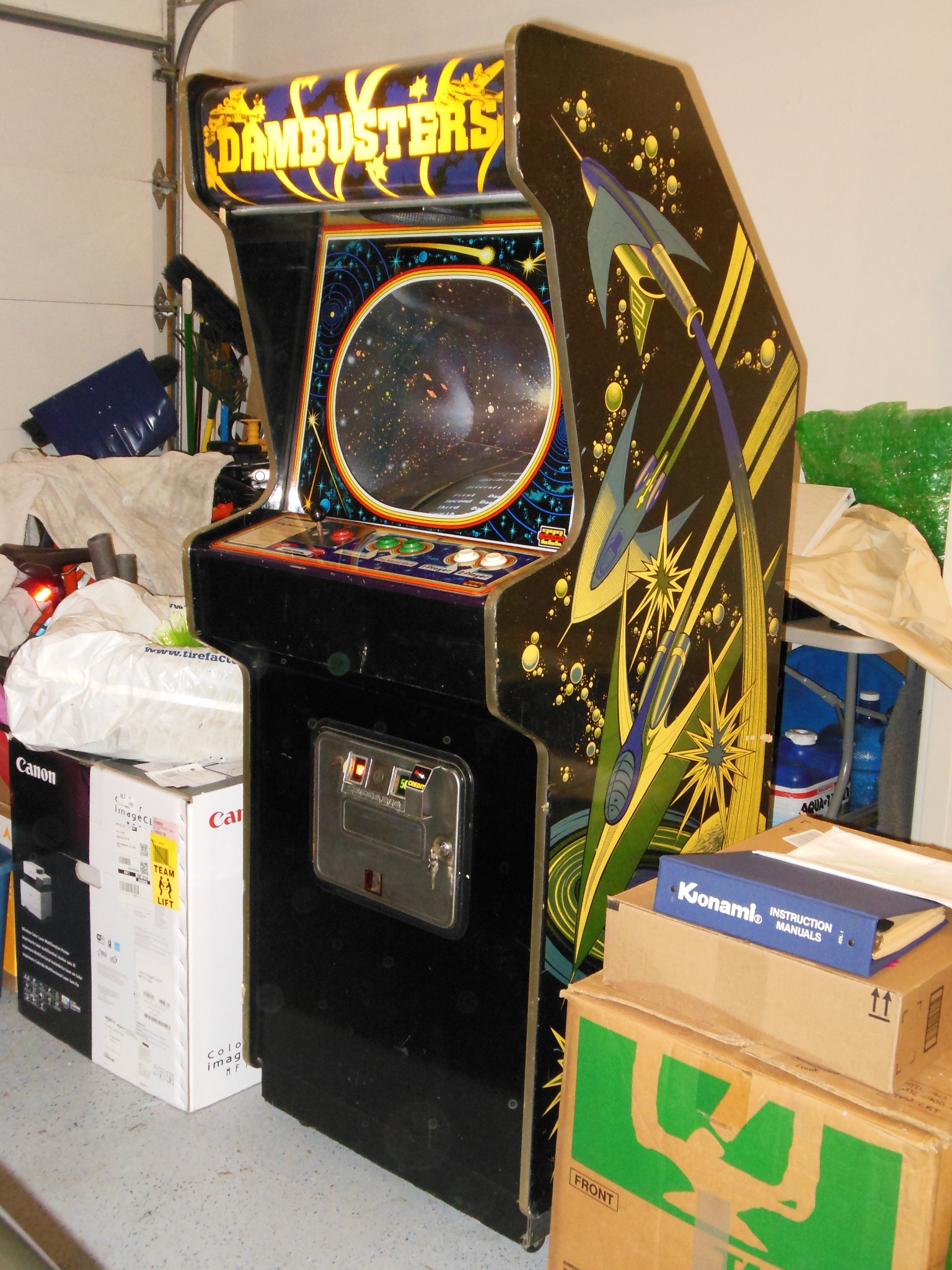
The cabinet has the alternative artwork seen on the Space Fortress flyer. The Dambusters conversion replaced the Quasar marque with a clear marque and Dambusters Plexiroll behind it. The Quasar control panel has additional cut outs for control labels, a joystick and Dambusters instruction sheet. The control panel conversion overall was pretty good.
The monitor glass and surround were Quasar. The surround was complete but had been cut along both sides along the top of the monitor.
|
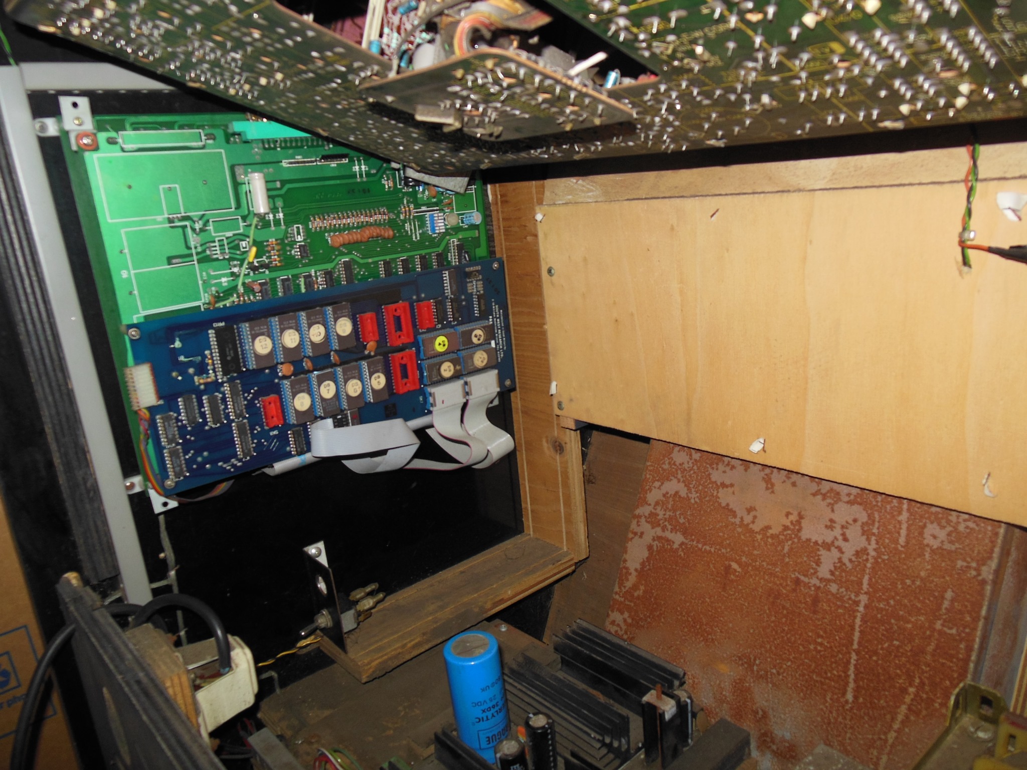
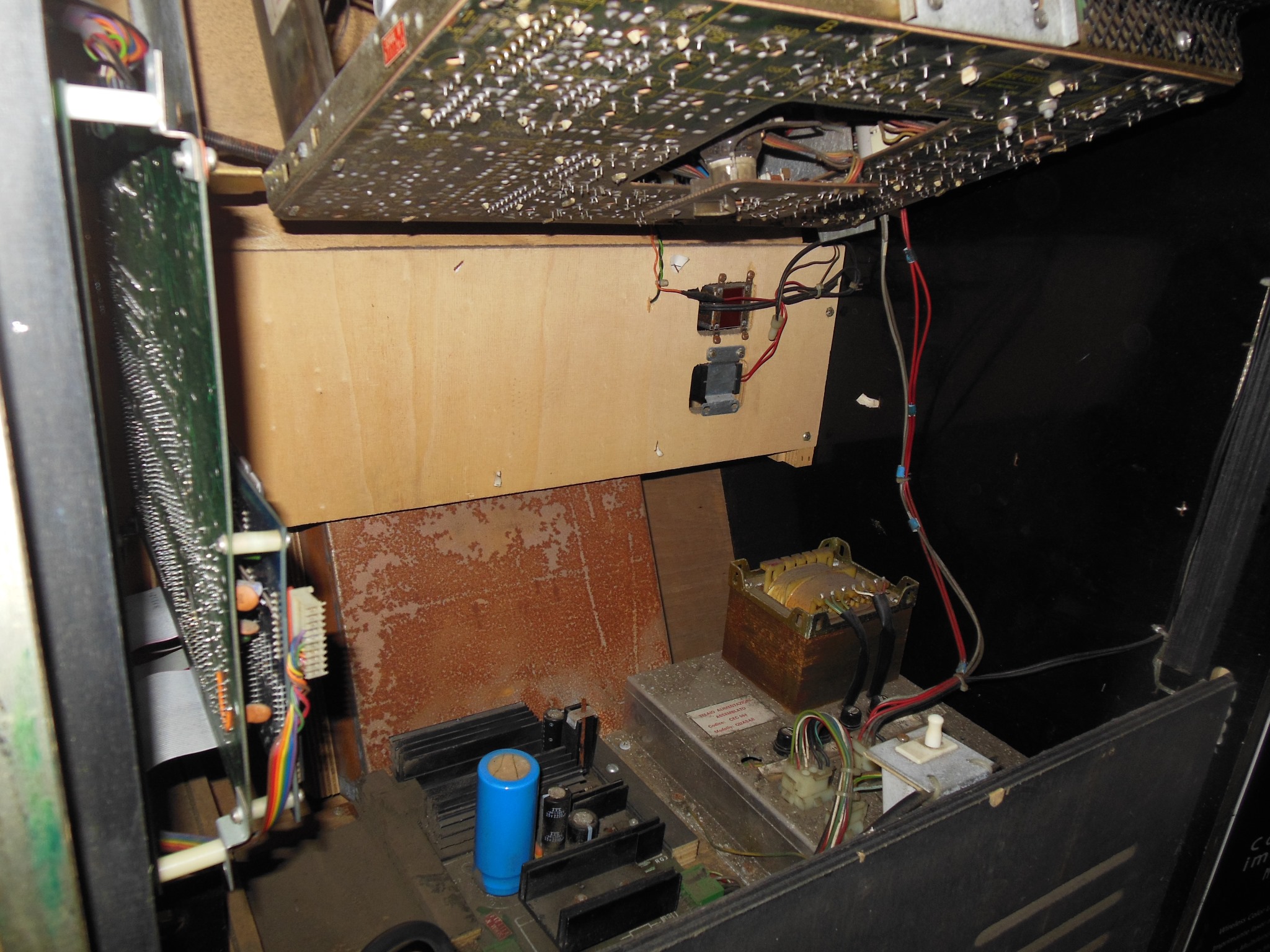
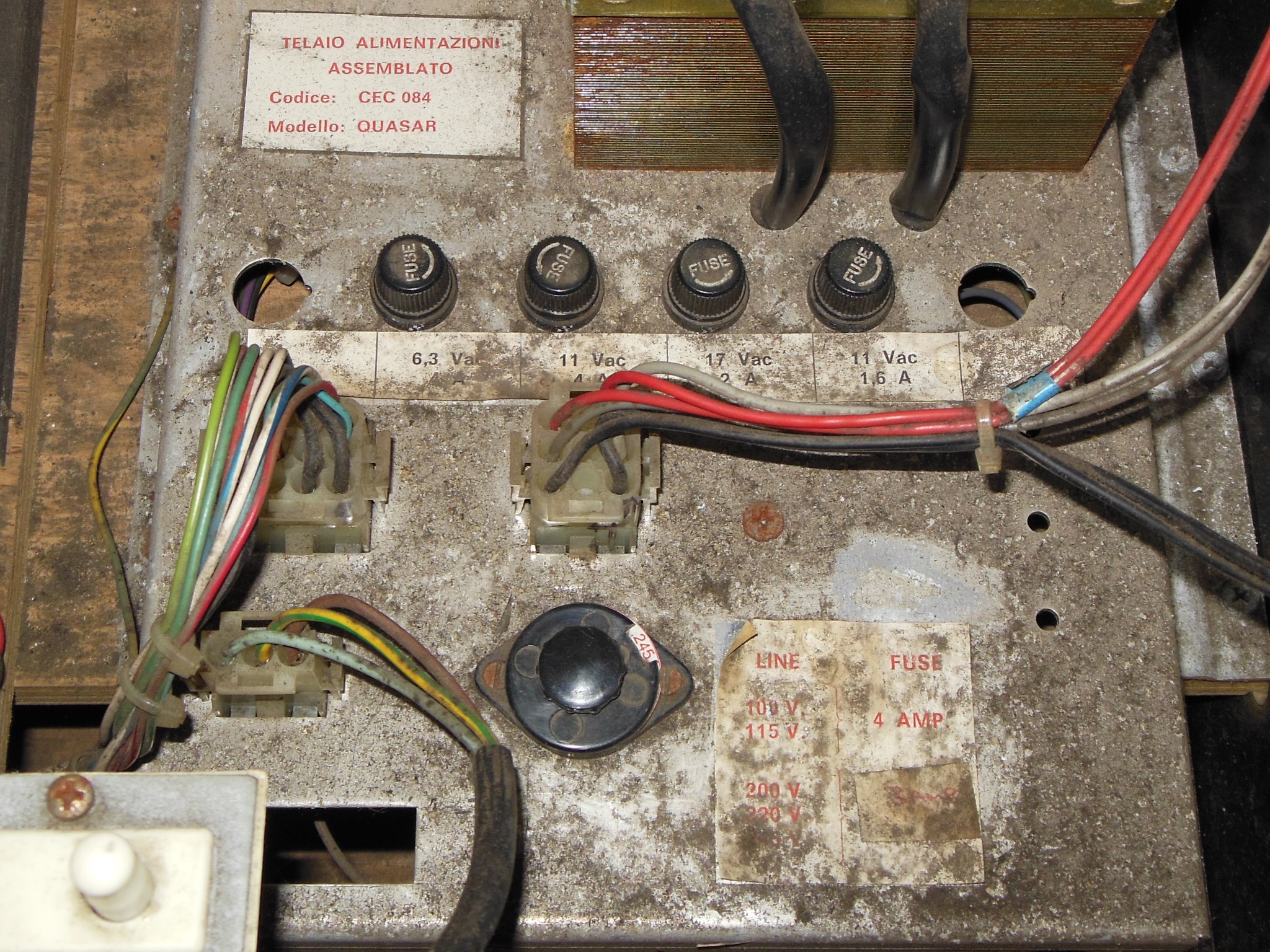
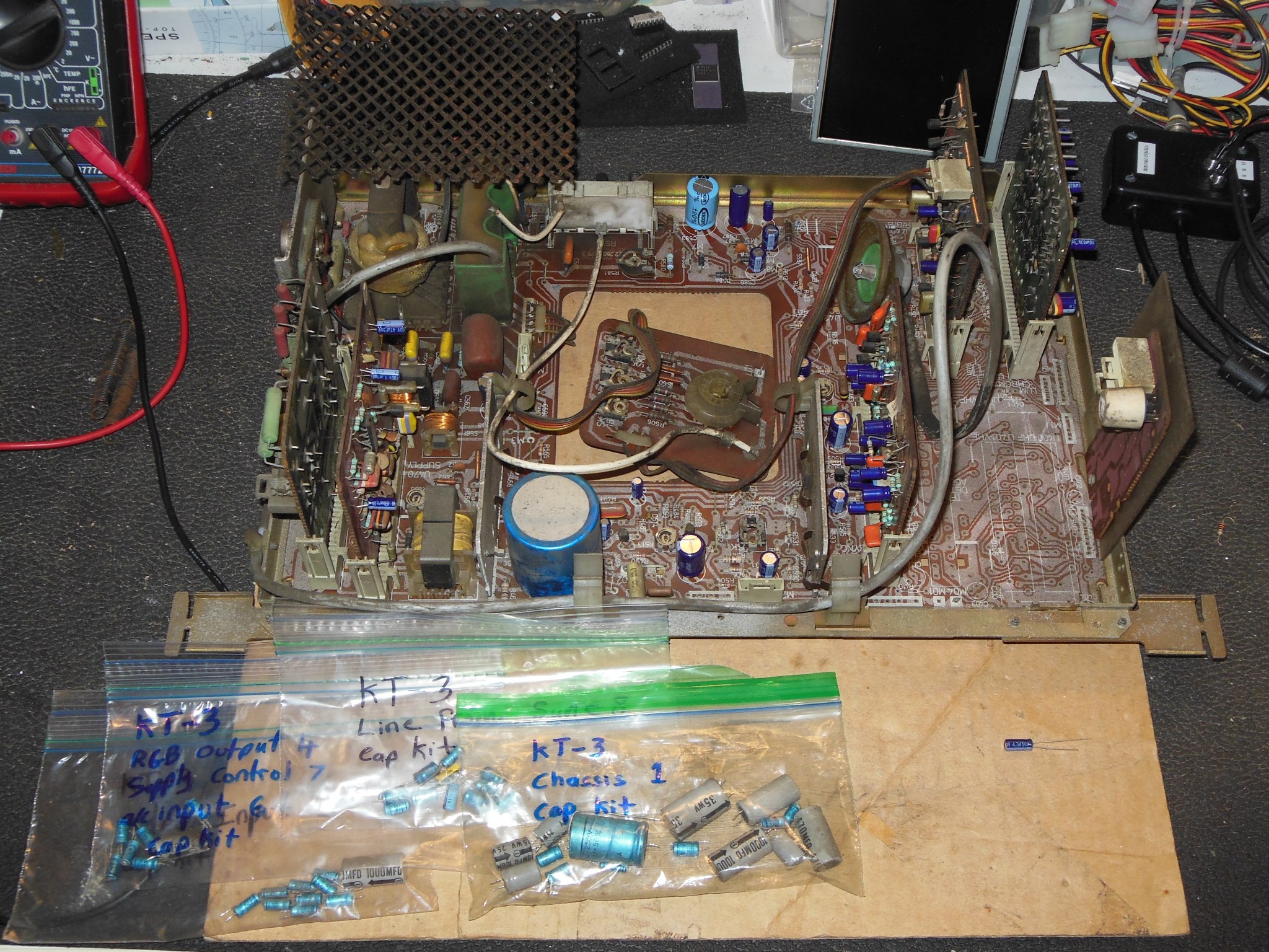
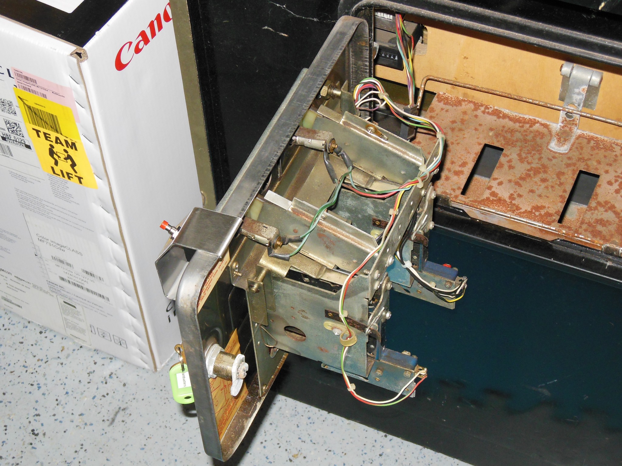
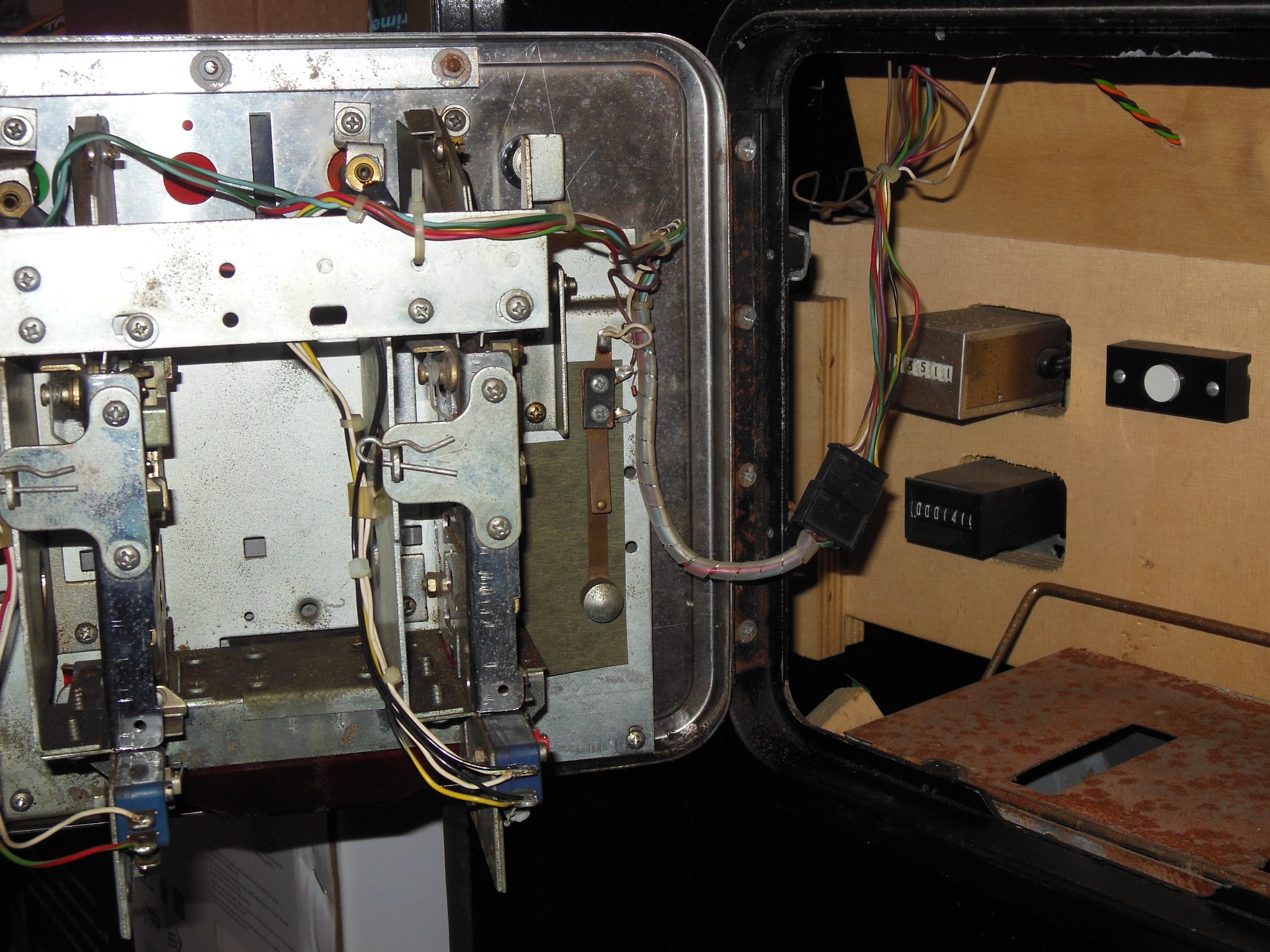
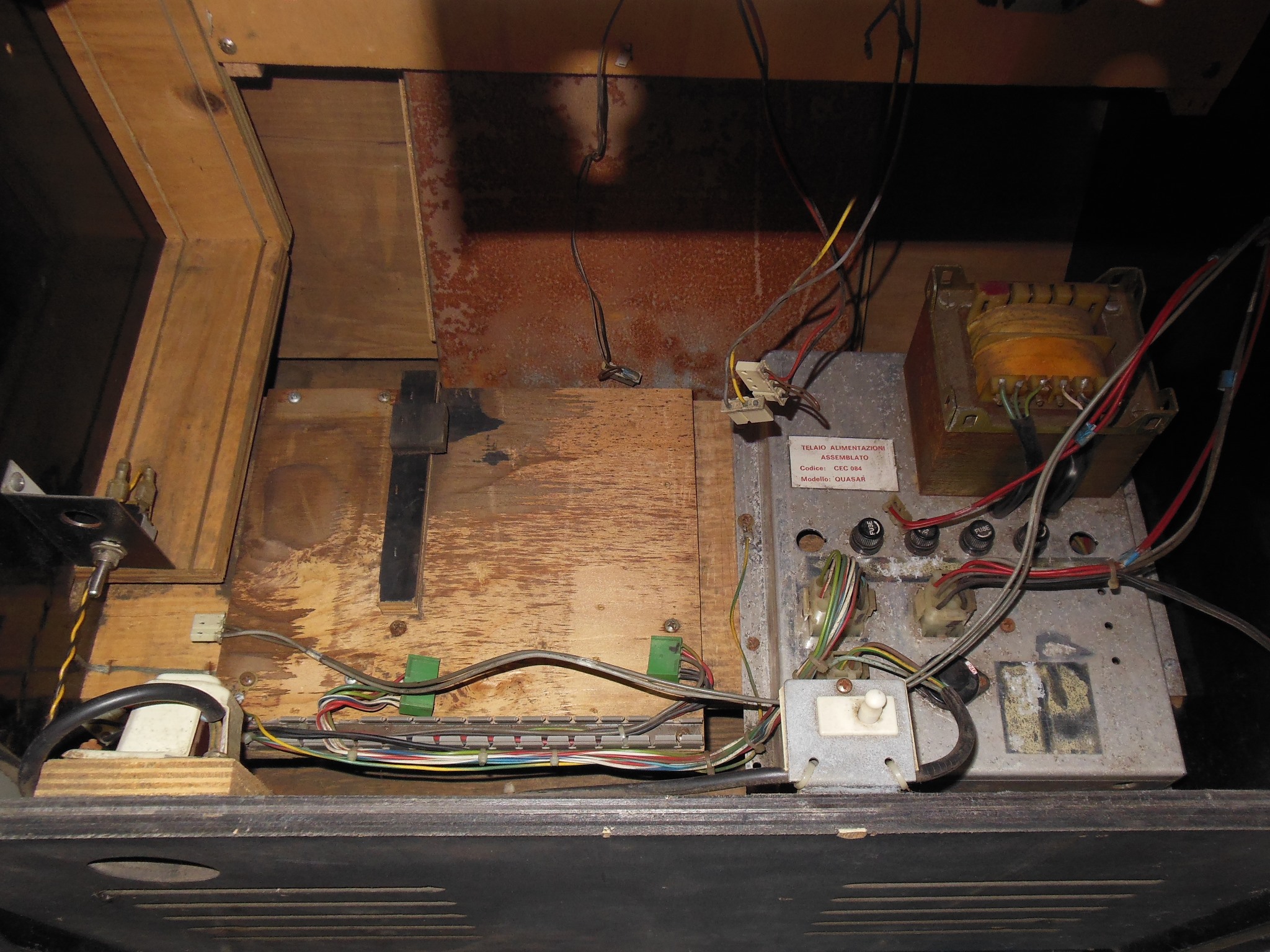
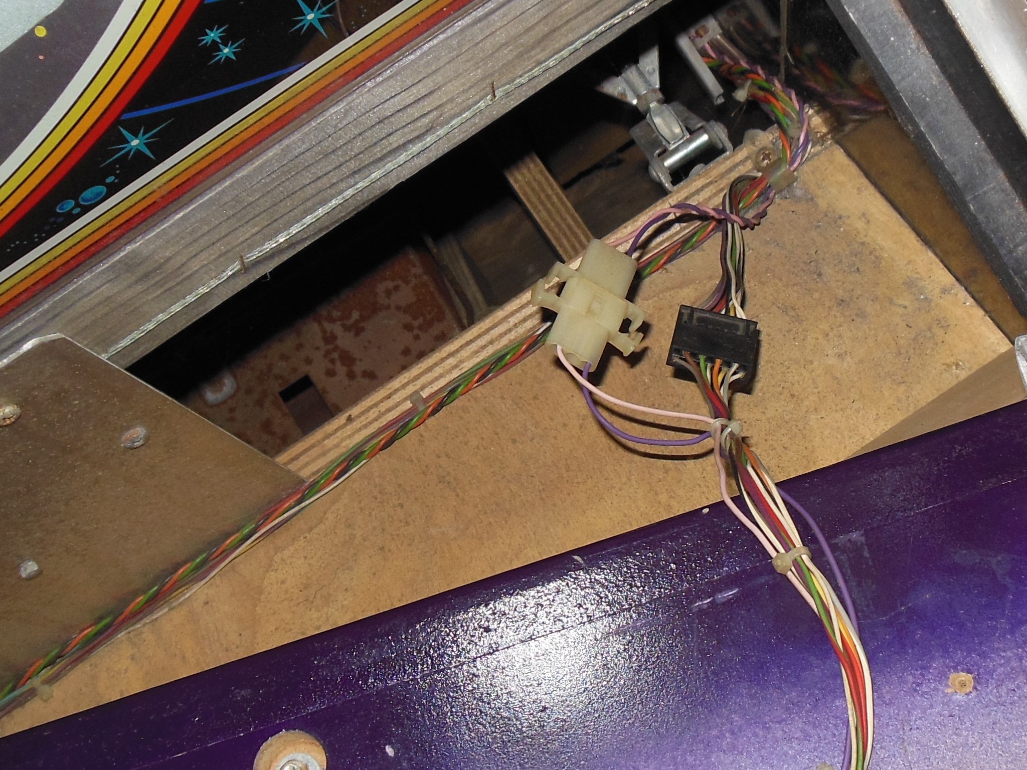
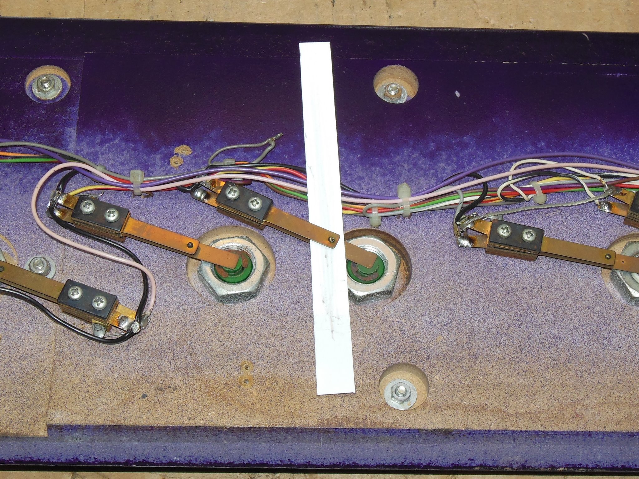
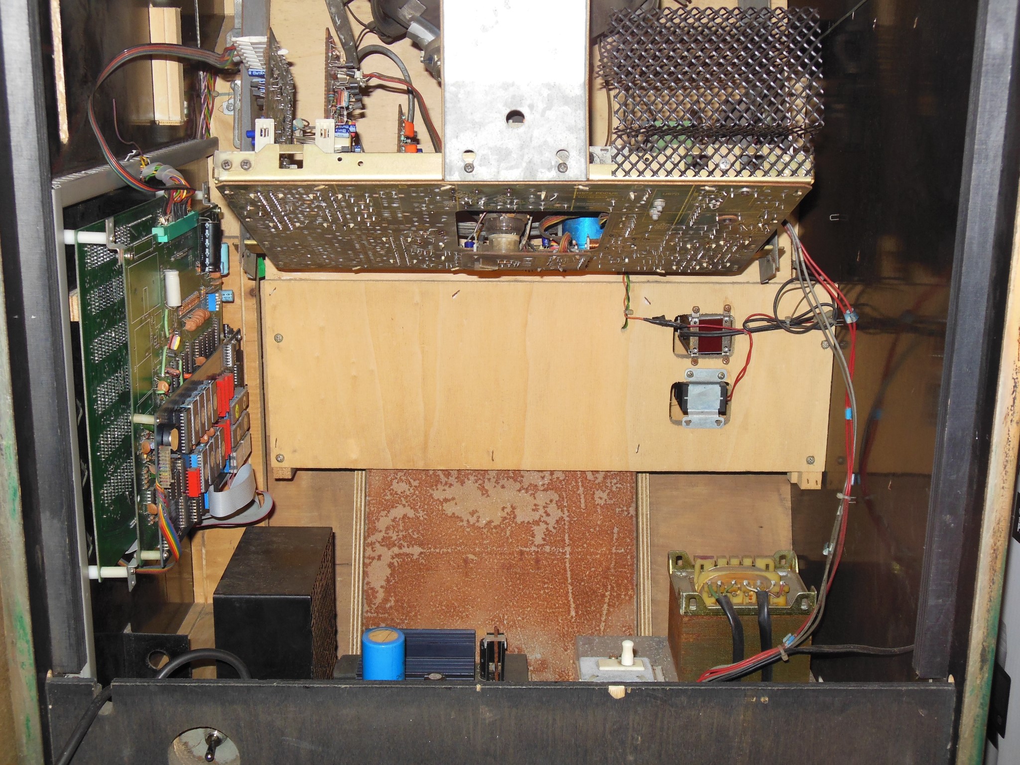
The power supply and most of the internal wiring looked to have been left intact from Quasar. A second coin counter had been added along with a toggle switch under the game PCB.
|
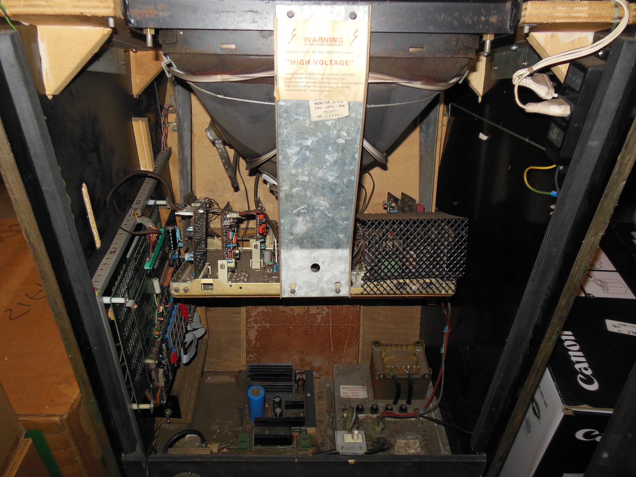
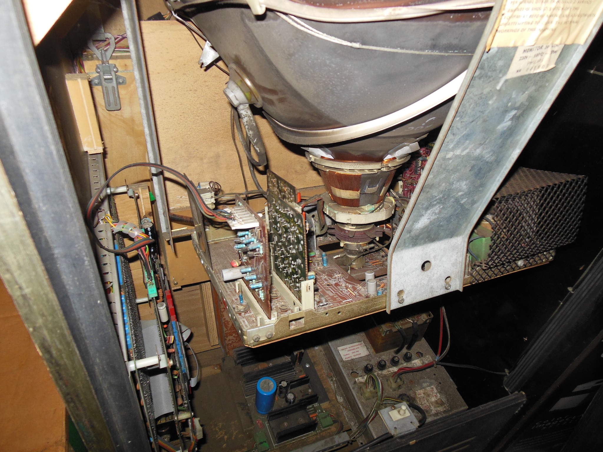
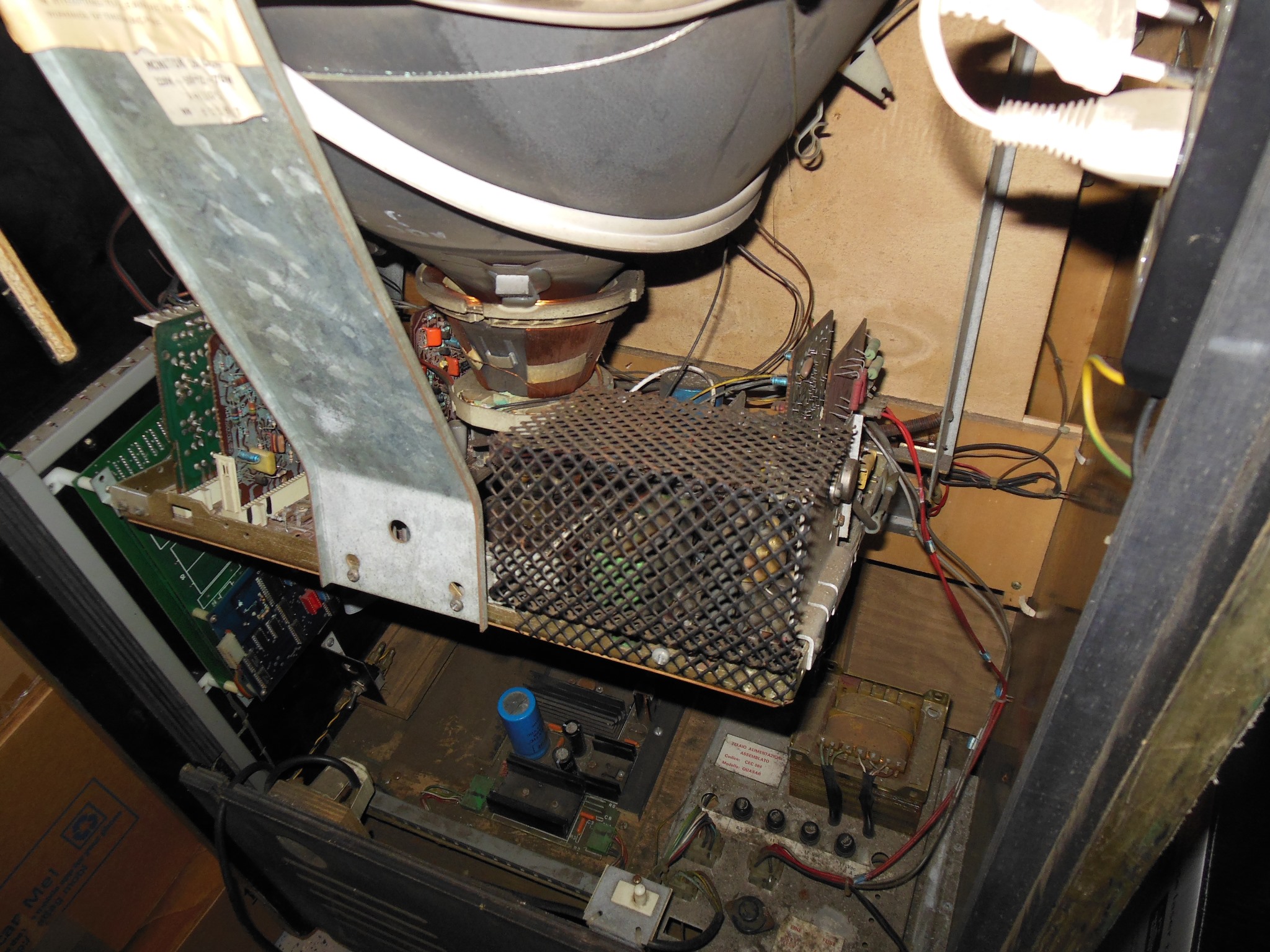
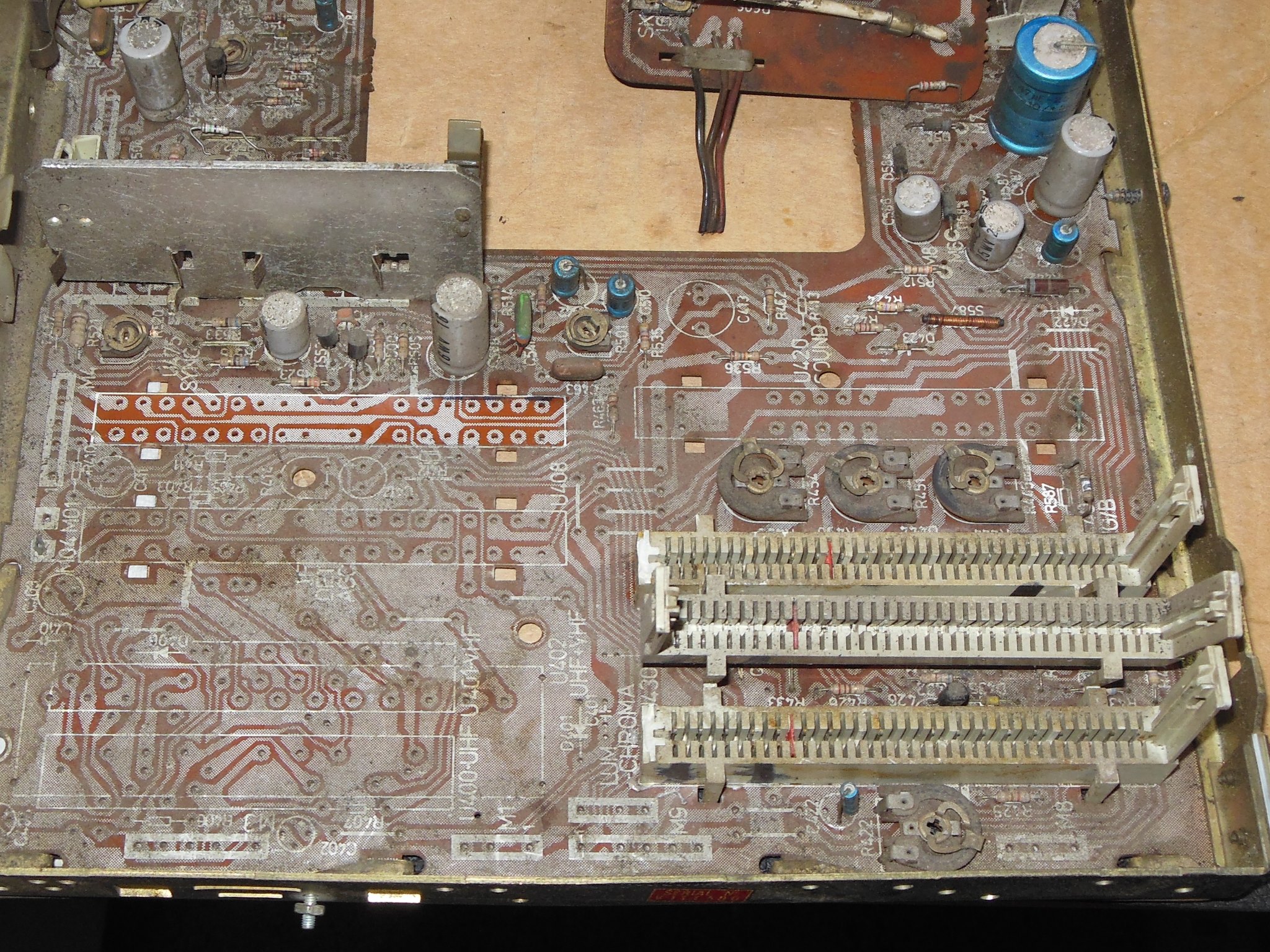
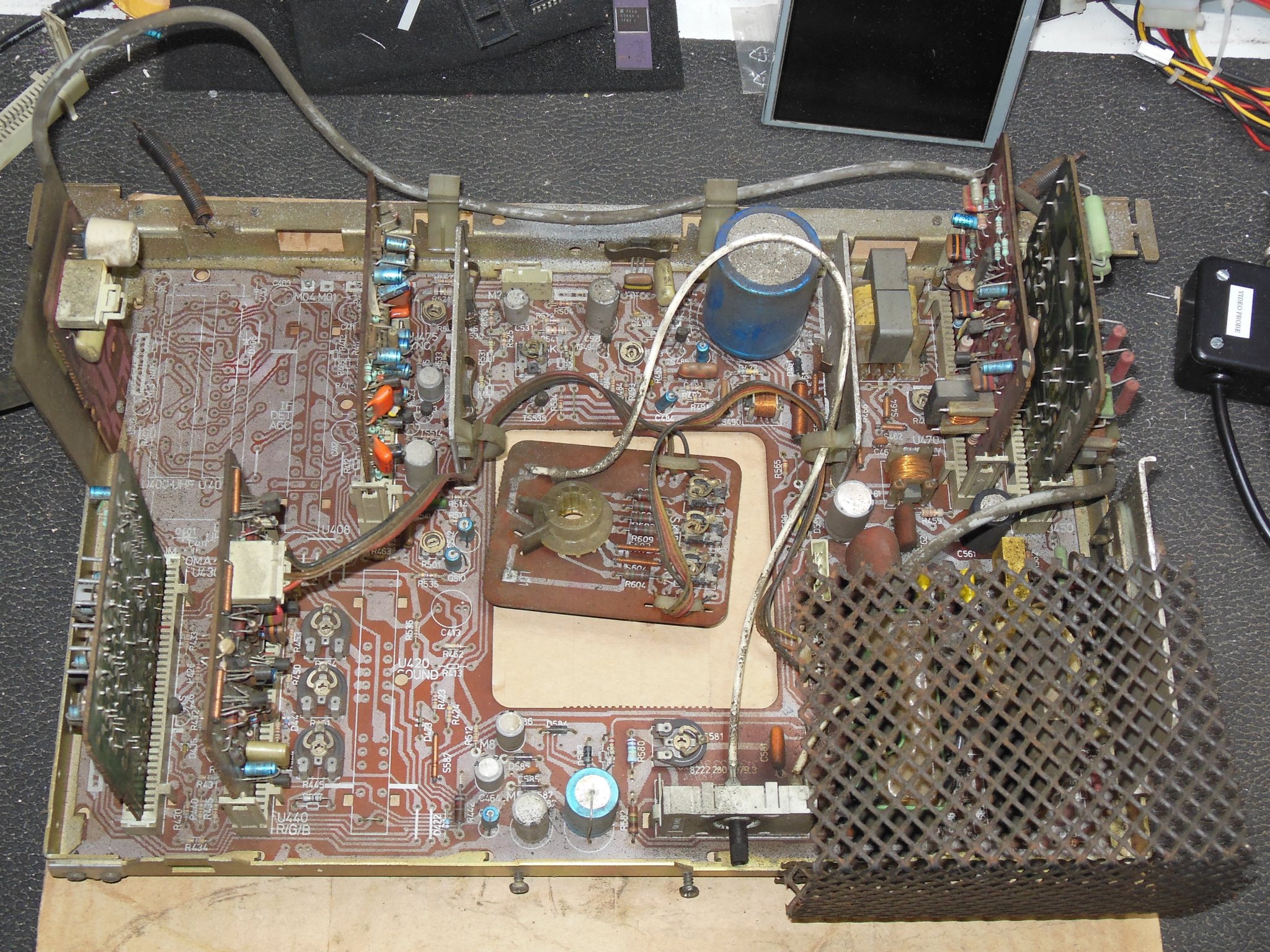
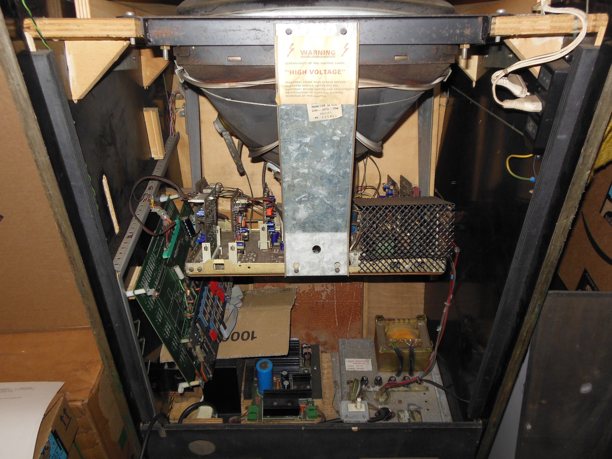
The original Philips KT-3 monitor was present & complete. There was at least one broken daughter board clip on the video input PCB, that had also been converted from Quasars inverted video to plain video input for Dambusters.
|
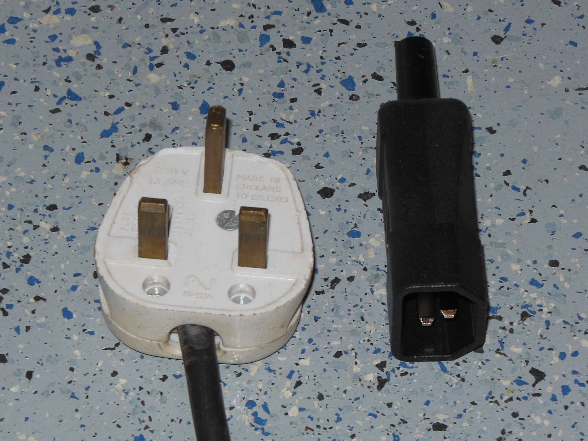
The UK plug was replaced with an IEC-14 plug for use with the 240 step up transformer and the voltage selector plug verified set to 245VAC.

|
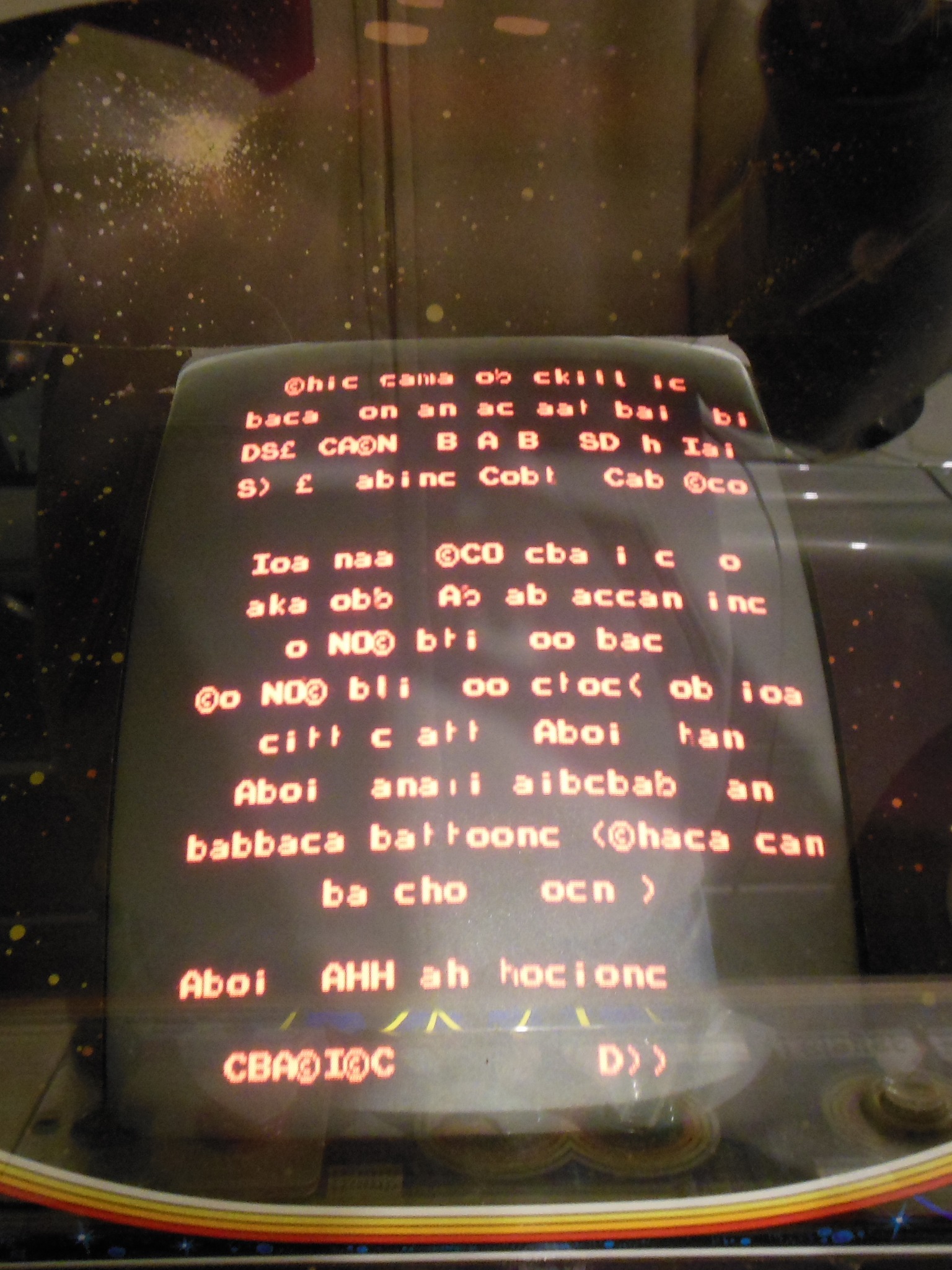
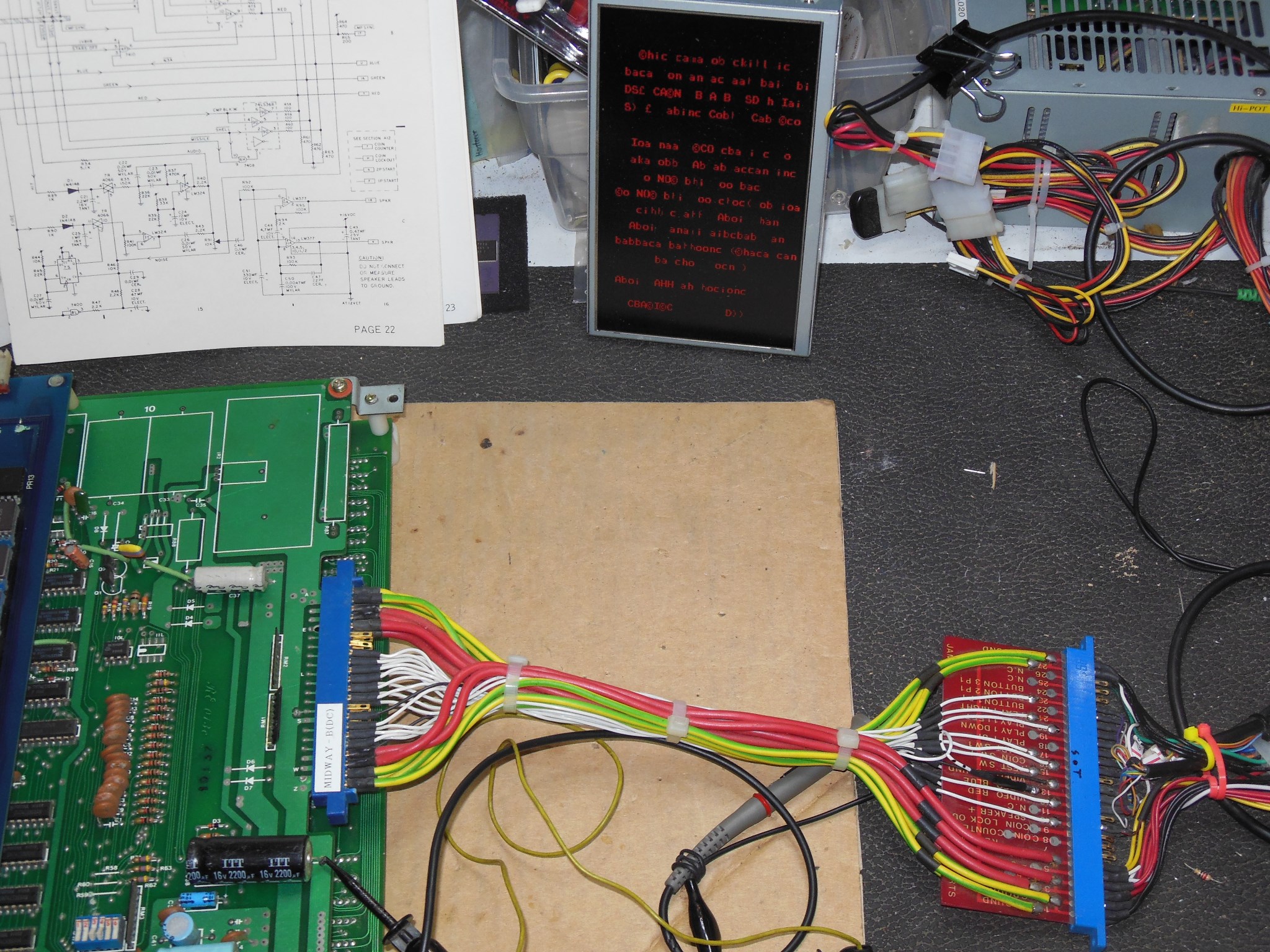
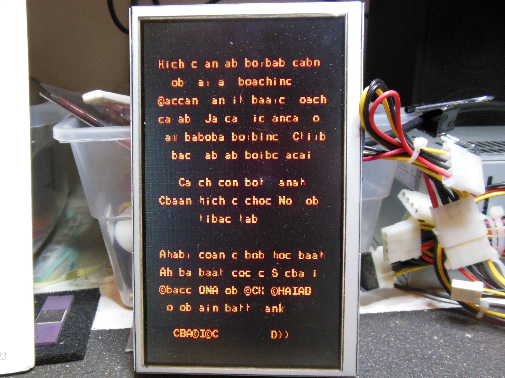
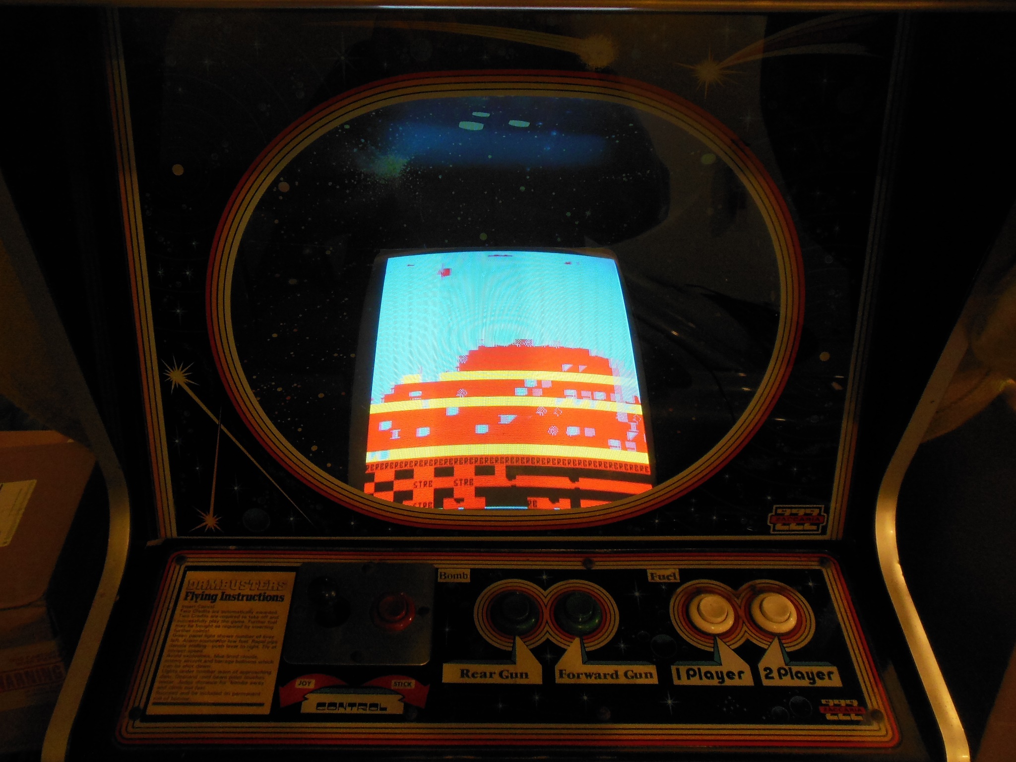
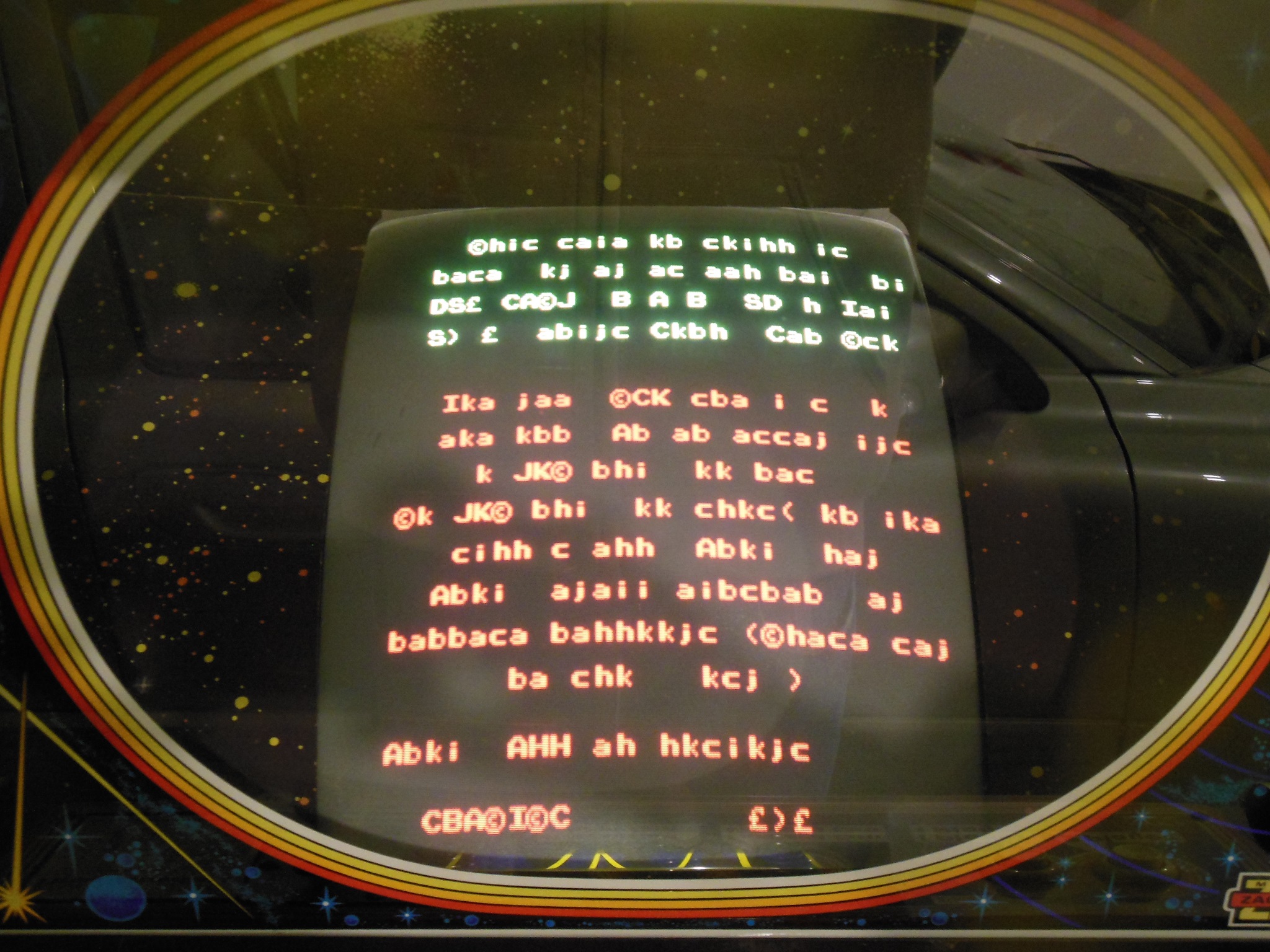
First power on yielded a working marque light, coin lights and a reasonable mostly red picture on the monitor. Initially the game board appeared to be not booting but after a couple of minutes, the game PCB booted up to a corrupted text screen.
|
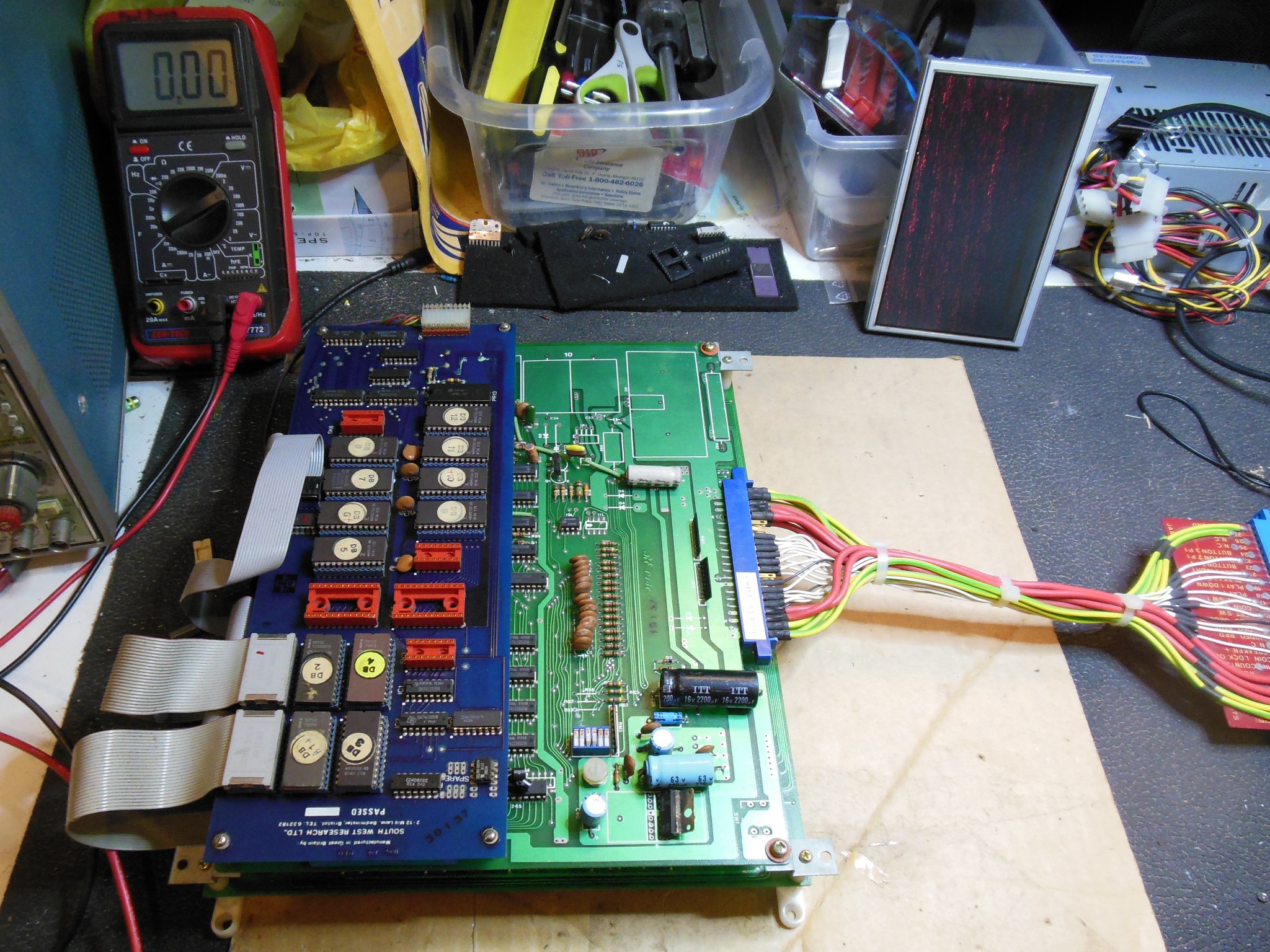
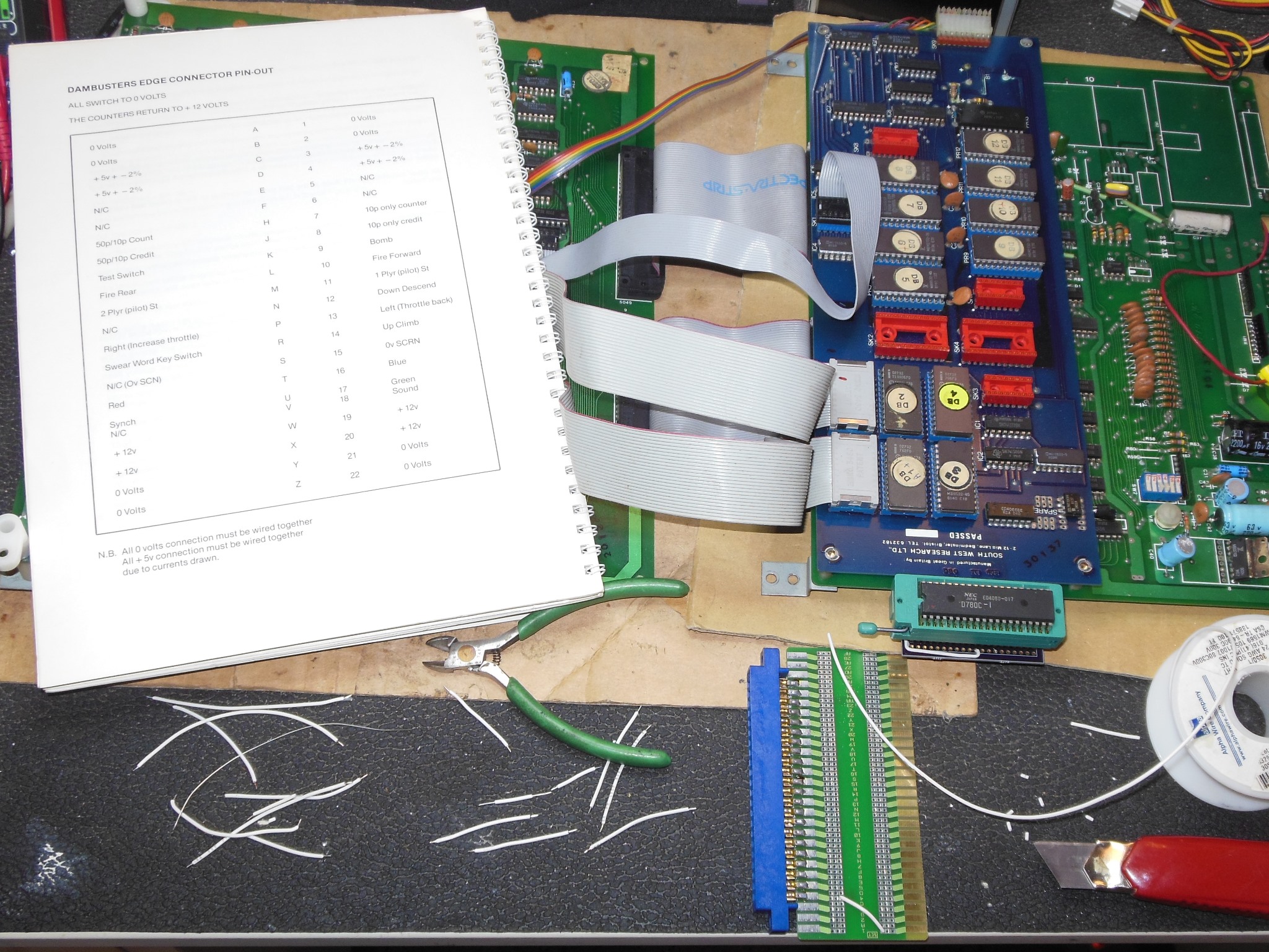
Pulling out the game PCB to test on the bench using a standard Midway Galaxians JAMMA adaptor found that there was no video sync and I vaguely recalled that this game PCB had the video output signals swapped on the edge connector.
|
Poking around with a scope and the Dambusters manual confirmed the location of the video sync pin on the edge connector and I added a couple of pins to the adaptor to allow the video sync & green to be swapped. This wouldn't give the correct colours but would at least show video to start with. The Dambusters control panel input pinout was completely different from Midway Galaxians and I'd need to make a dedicated adaptor for this game in future to properly test it on the bench.

|
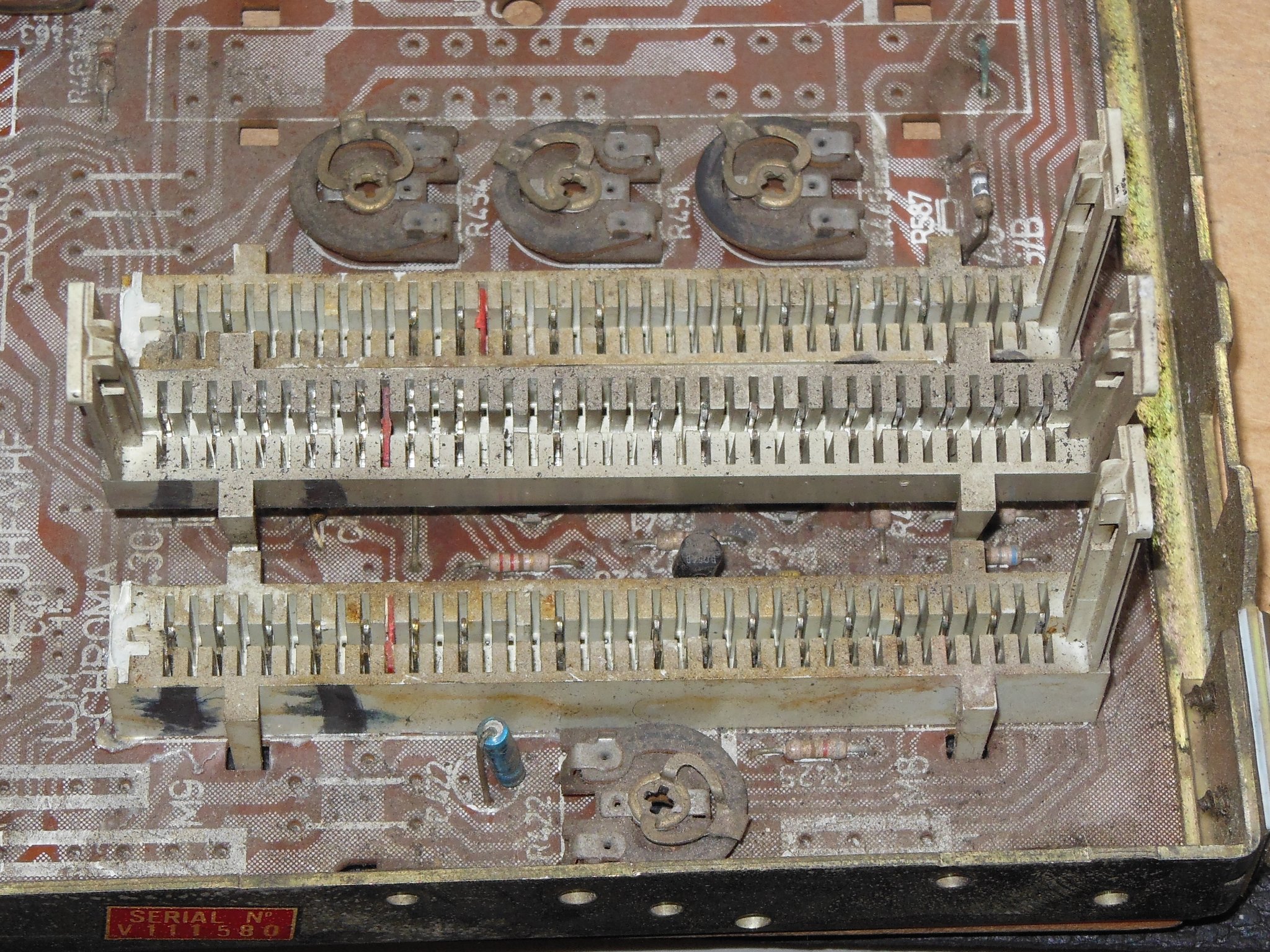
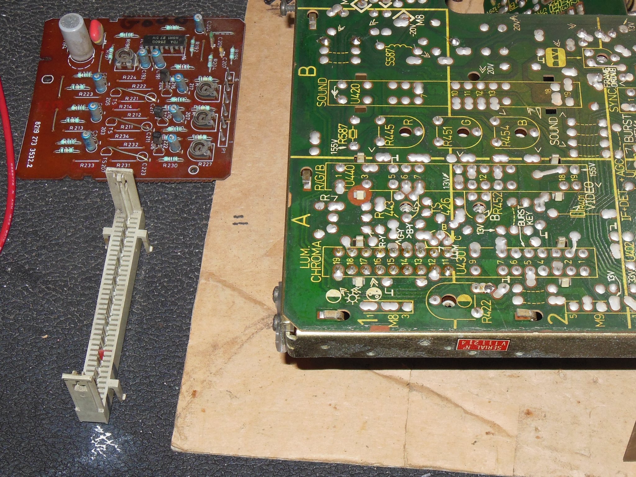
The Philips KT-3 monitor chassis had both card guides on the video input daughter PCB snapped off so I needed to recover a replacement from a scrap chassis. Though all the connectors on this chassis look the same, closer inspection found differences in the pins that that were populated in the connector. On the scrap chassis the original video input PCB connector was already broken however the connector on one of the other cards was a match, needing only a key plug change.
|
The broken video input PCB connector on the Dambusters KT-3 chassis was replaced.
|
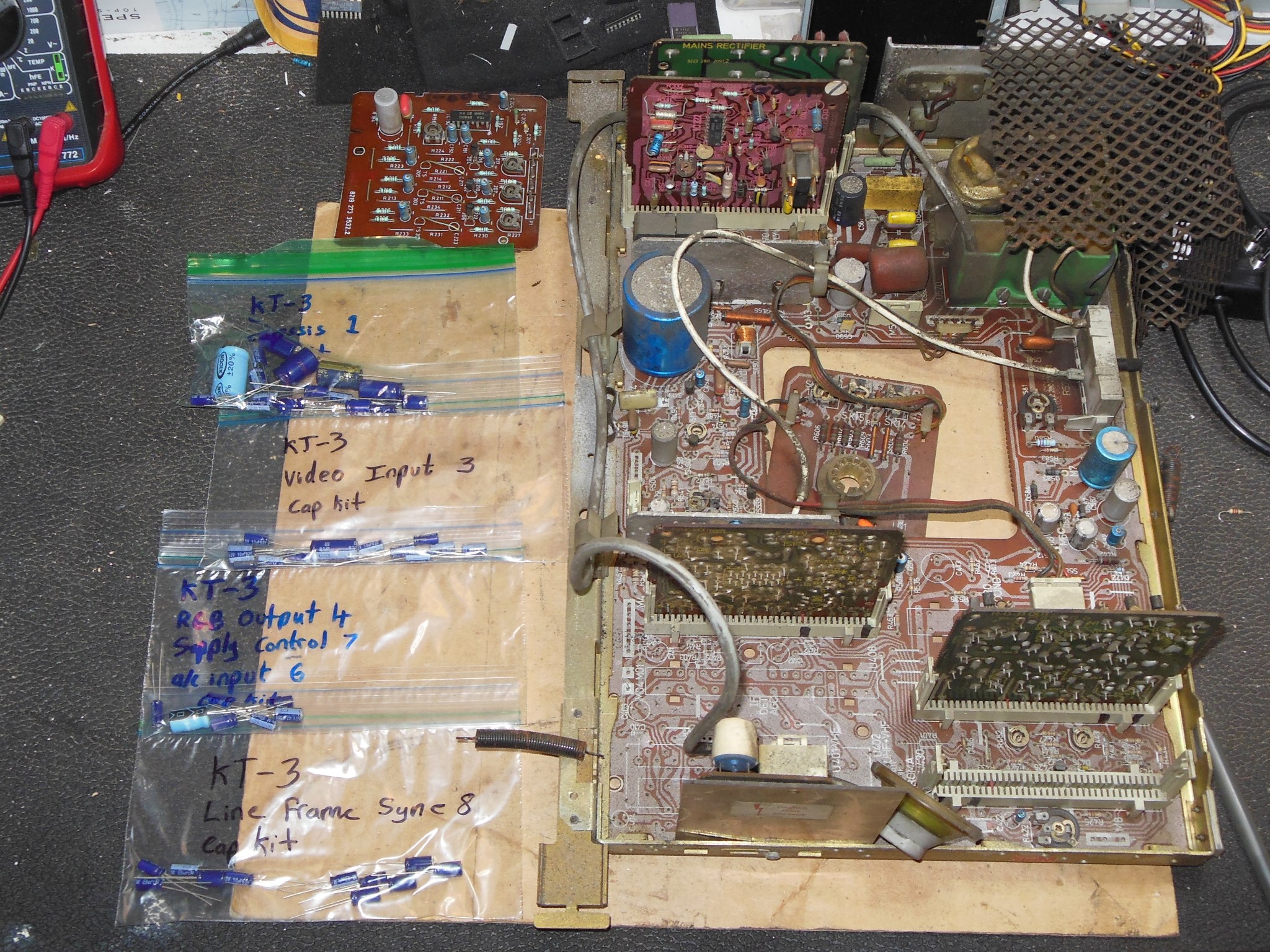
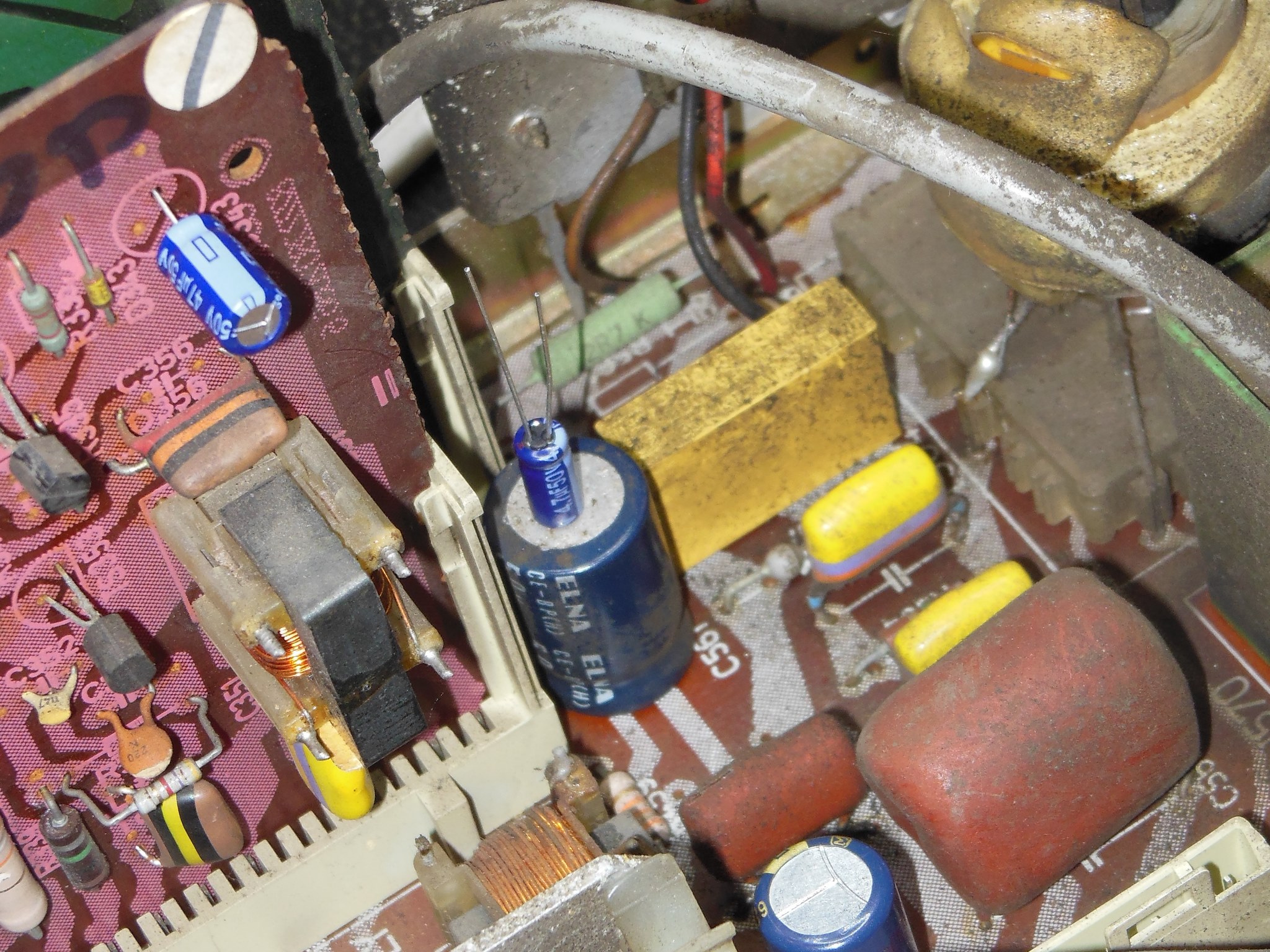
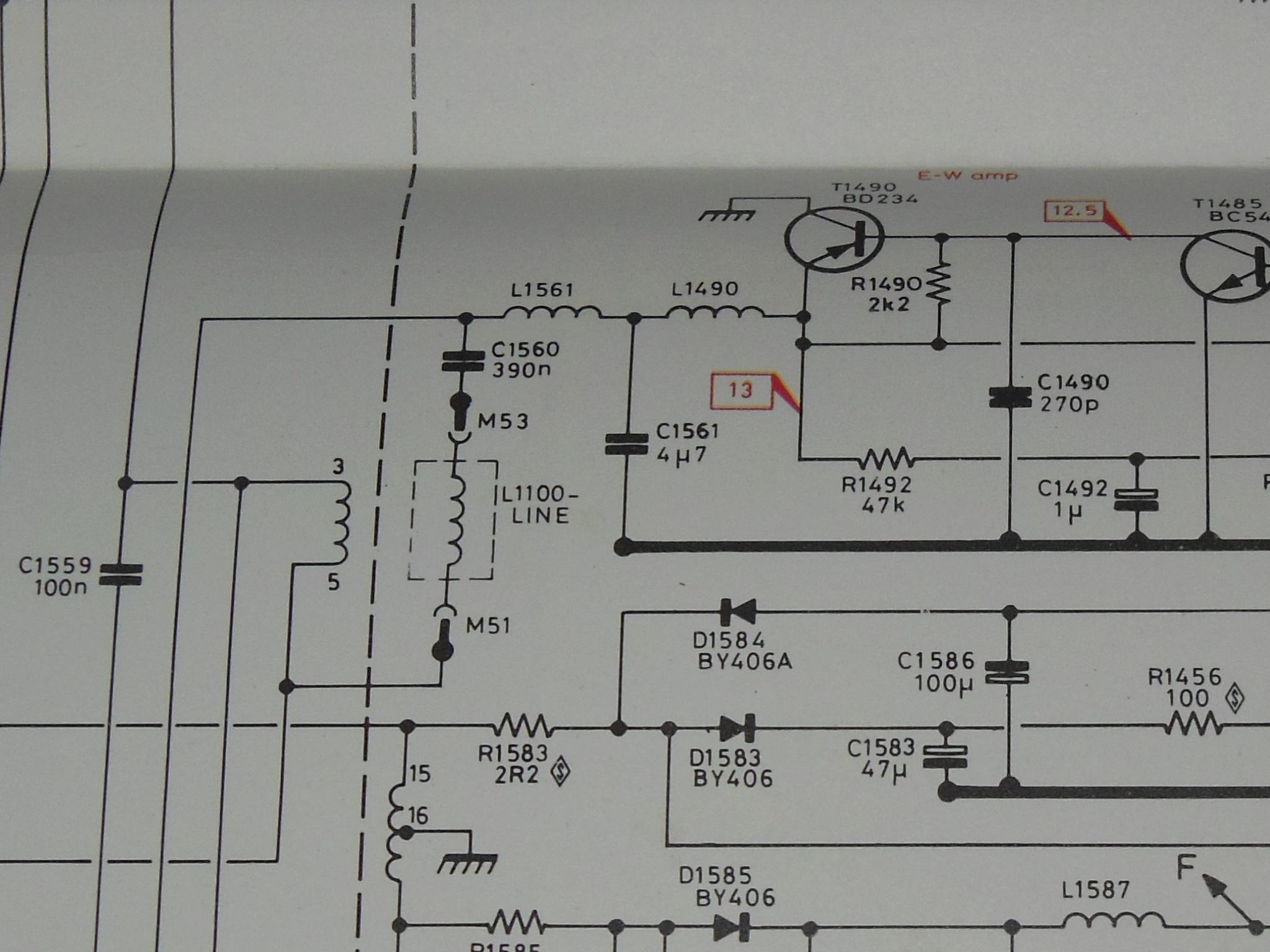
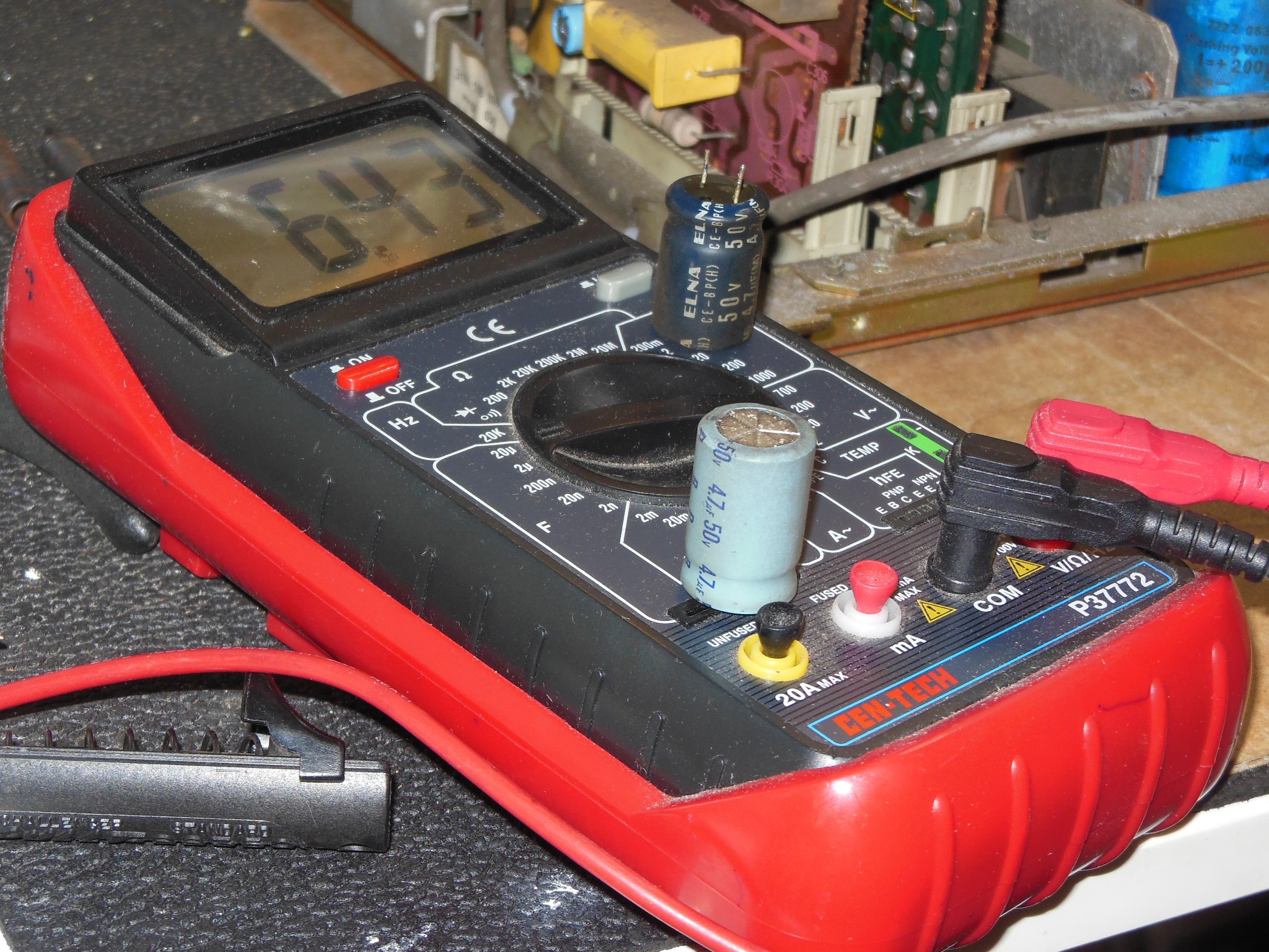
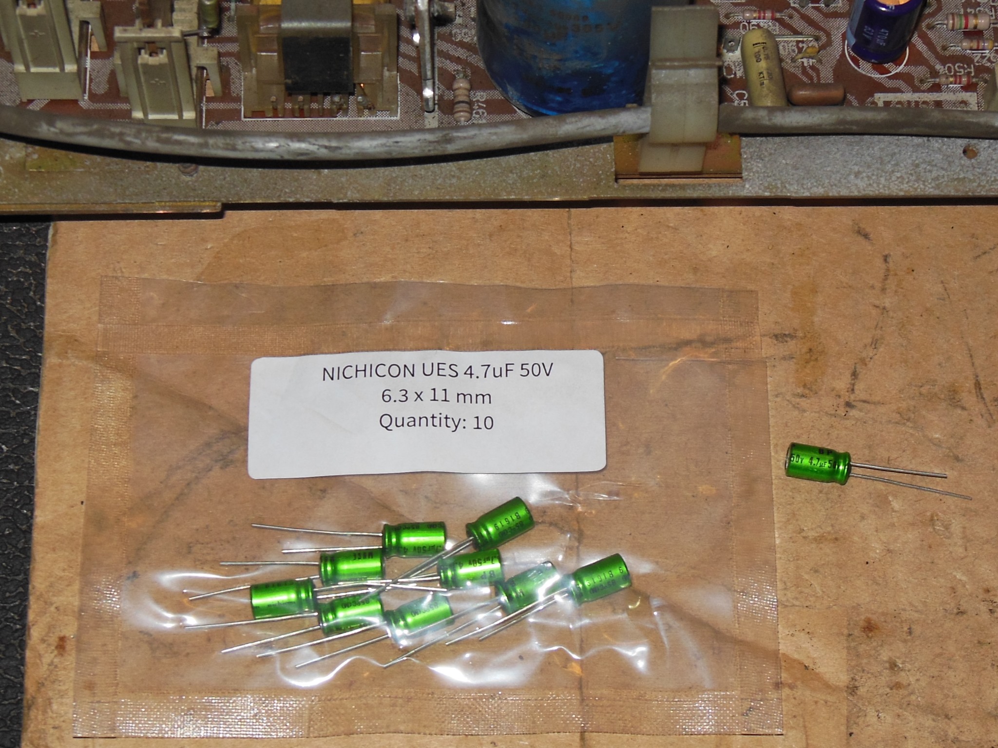
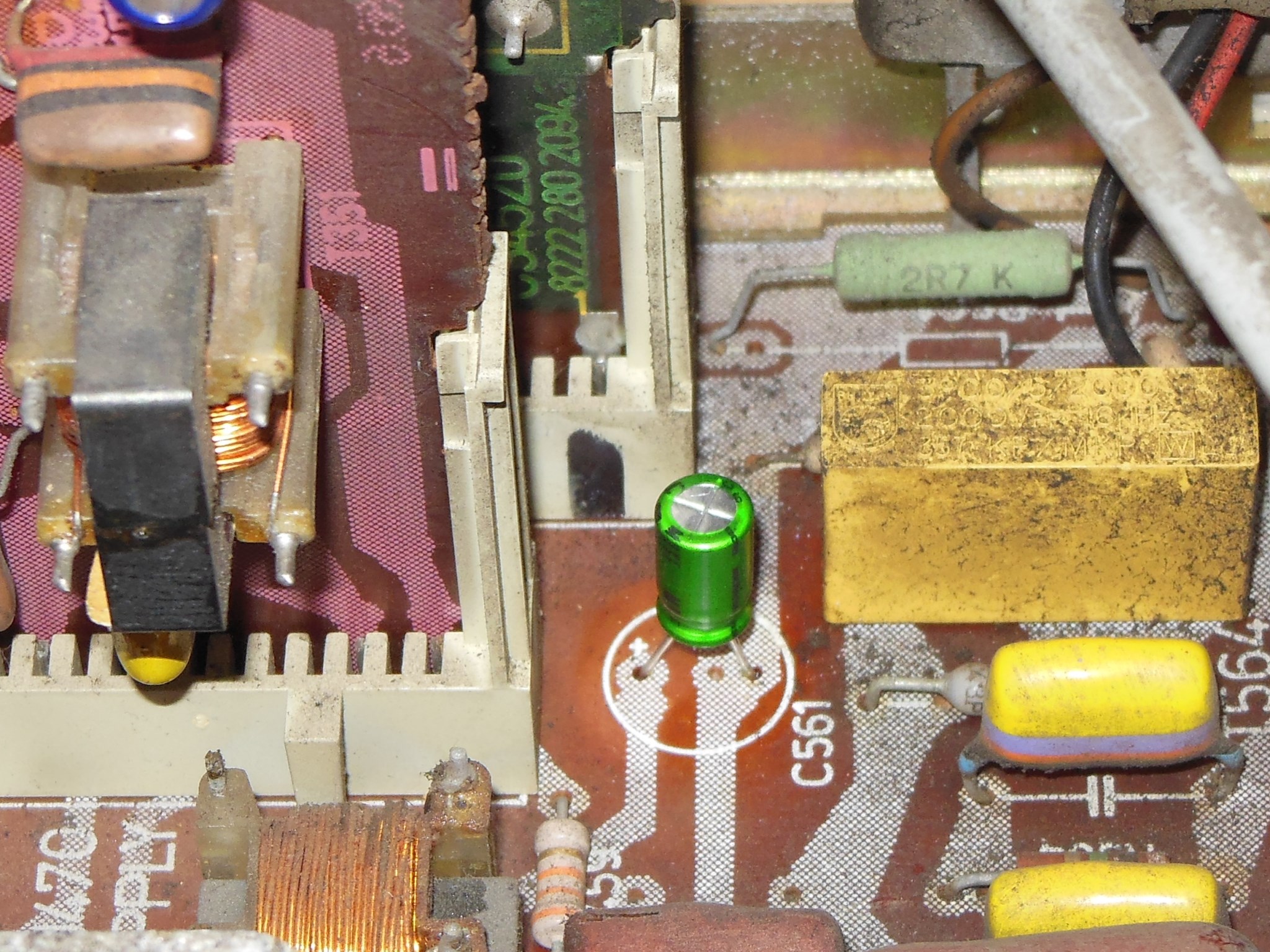
For the cap kit I'd already made up several sets that I'd been using previously but it was only now that I noticed a significant size disparity between what was fitted in C561 versus the replacement. Closer inspection found the original C561 to be non-polar, that was confirmed on the schematic. I'd not noticed during prior cap kits, some of which had been running in the show for many hours without any apparent issue.
|
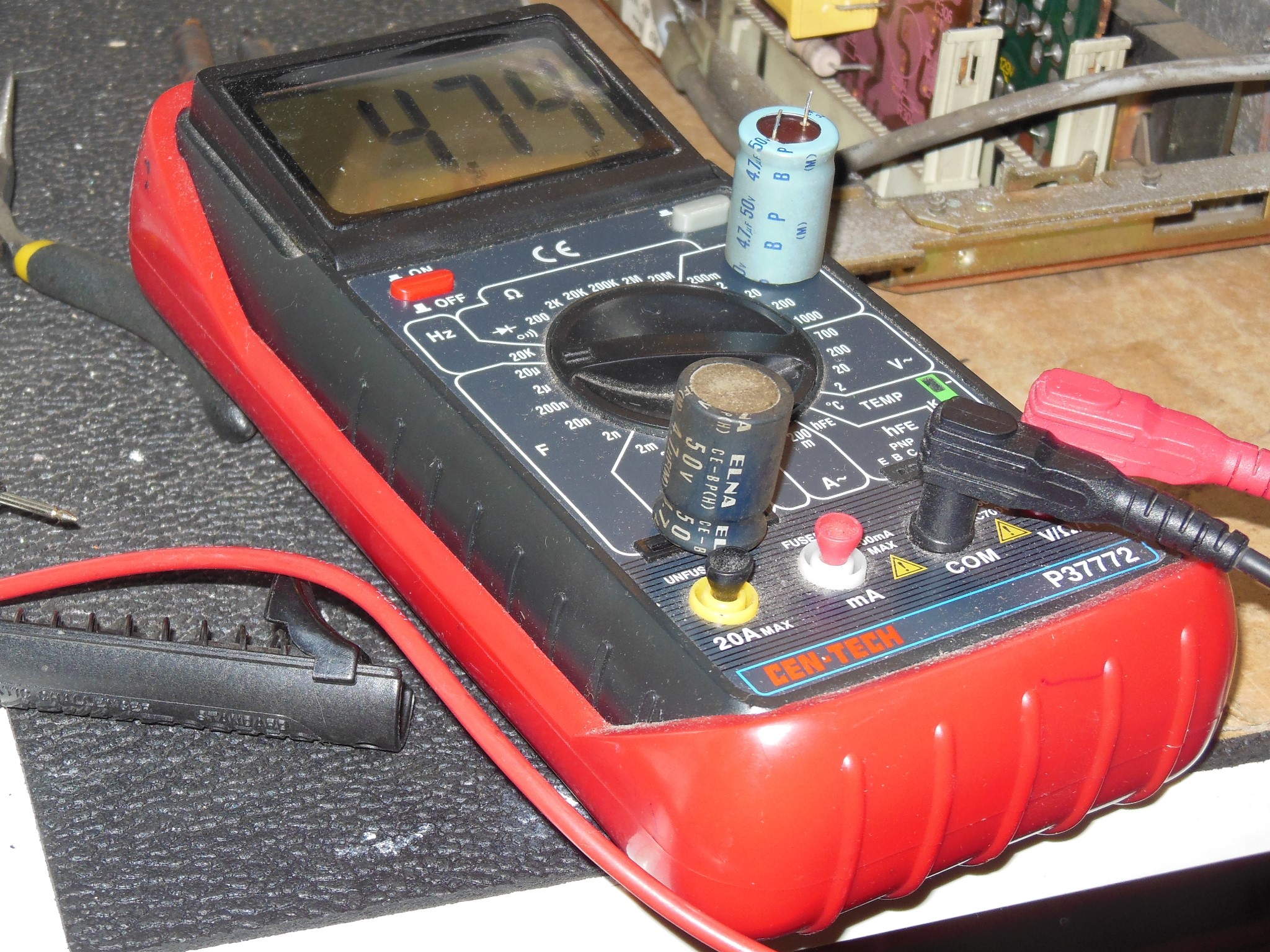
I completed the cap kit aside from C561 and considered skipping it to leave as is. Since I'd kept all the removed capacitors from prior kits, I decided to check on the health of the non-polar capacitors to confirm. Alas, at least one of the prior removed non-polar capacitors was bad so I ordered non-polar replacements both for this chassis and to correct prior chassis kits :|
|
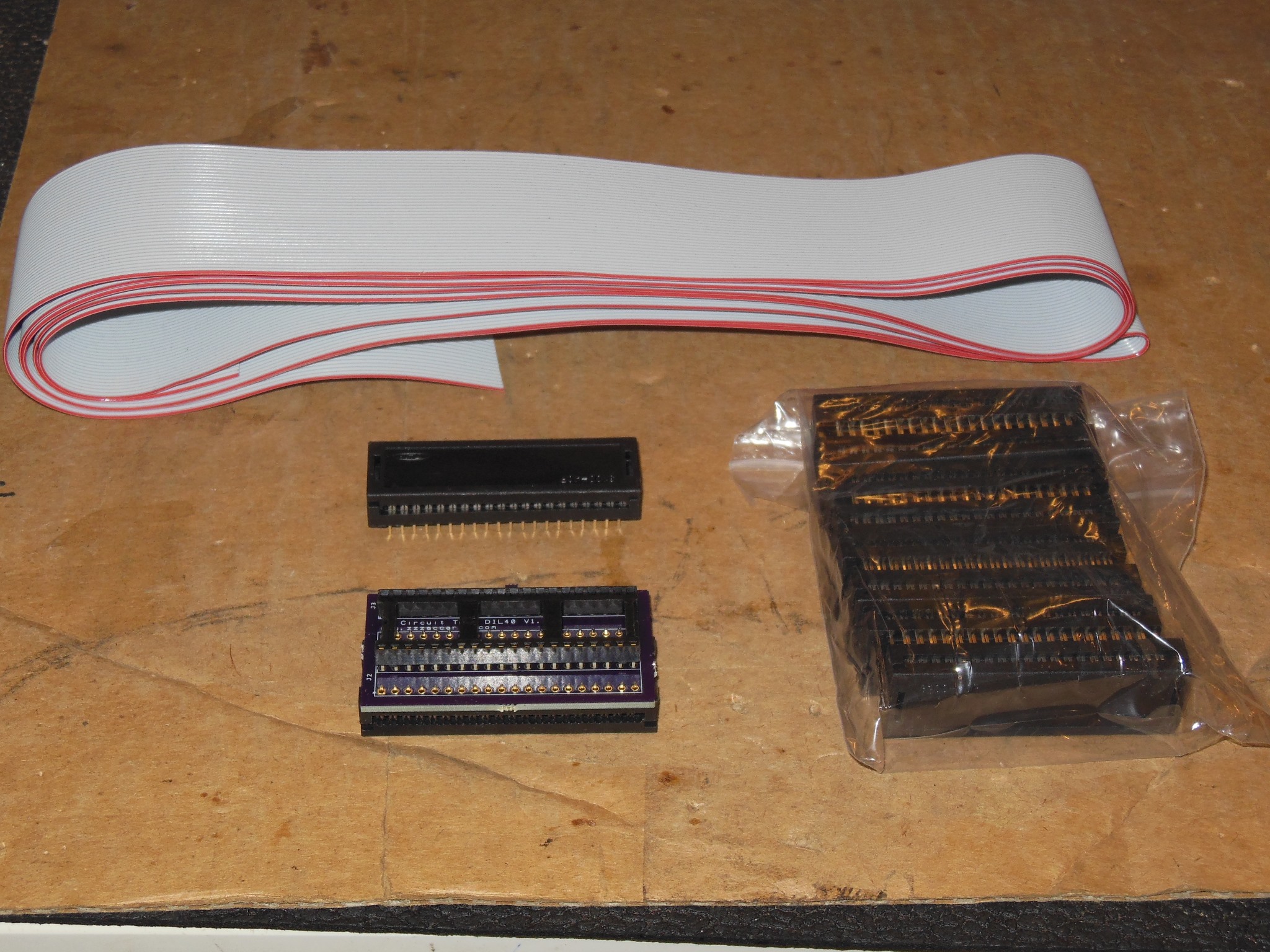
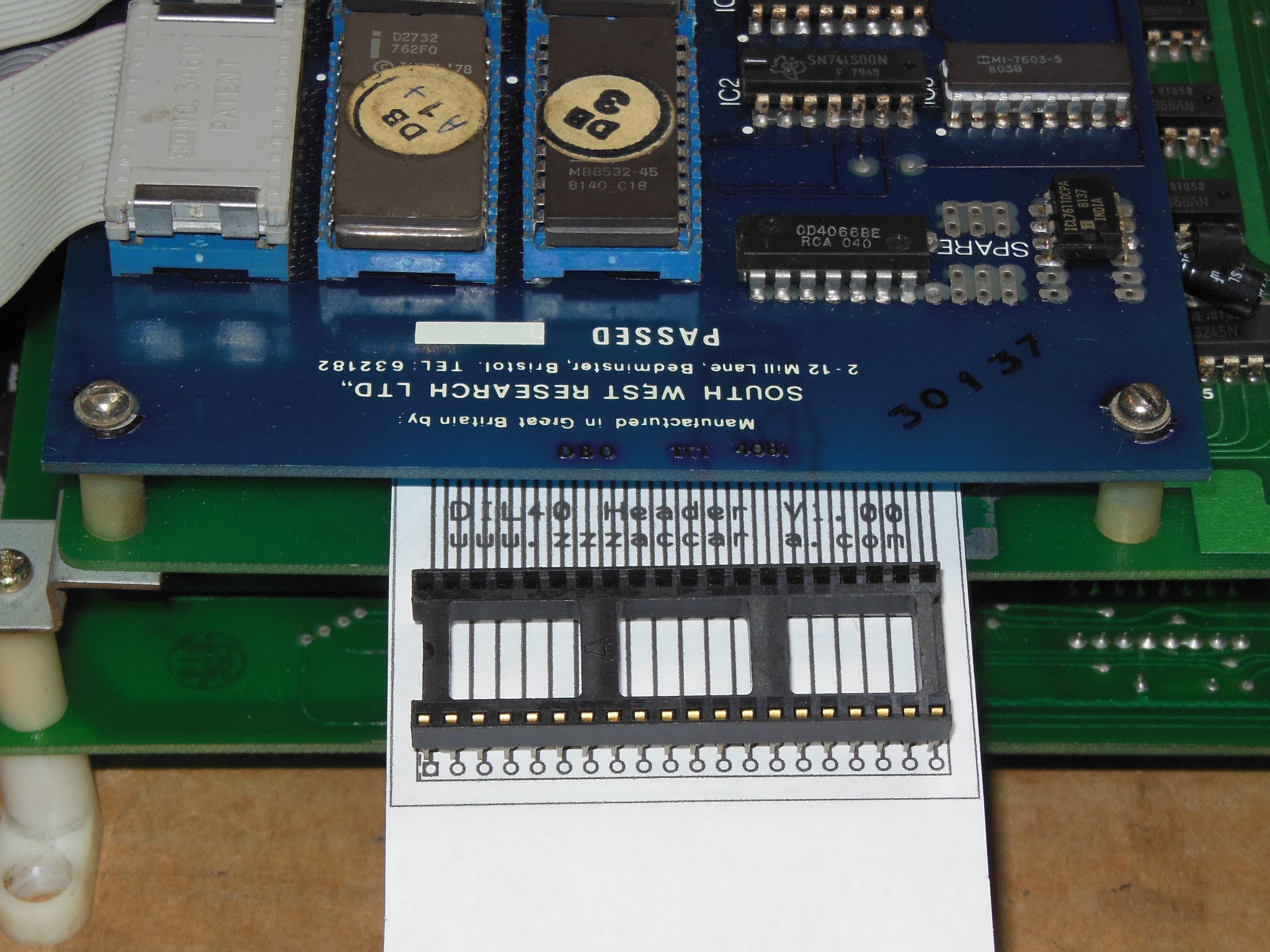
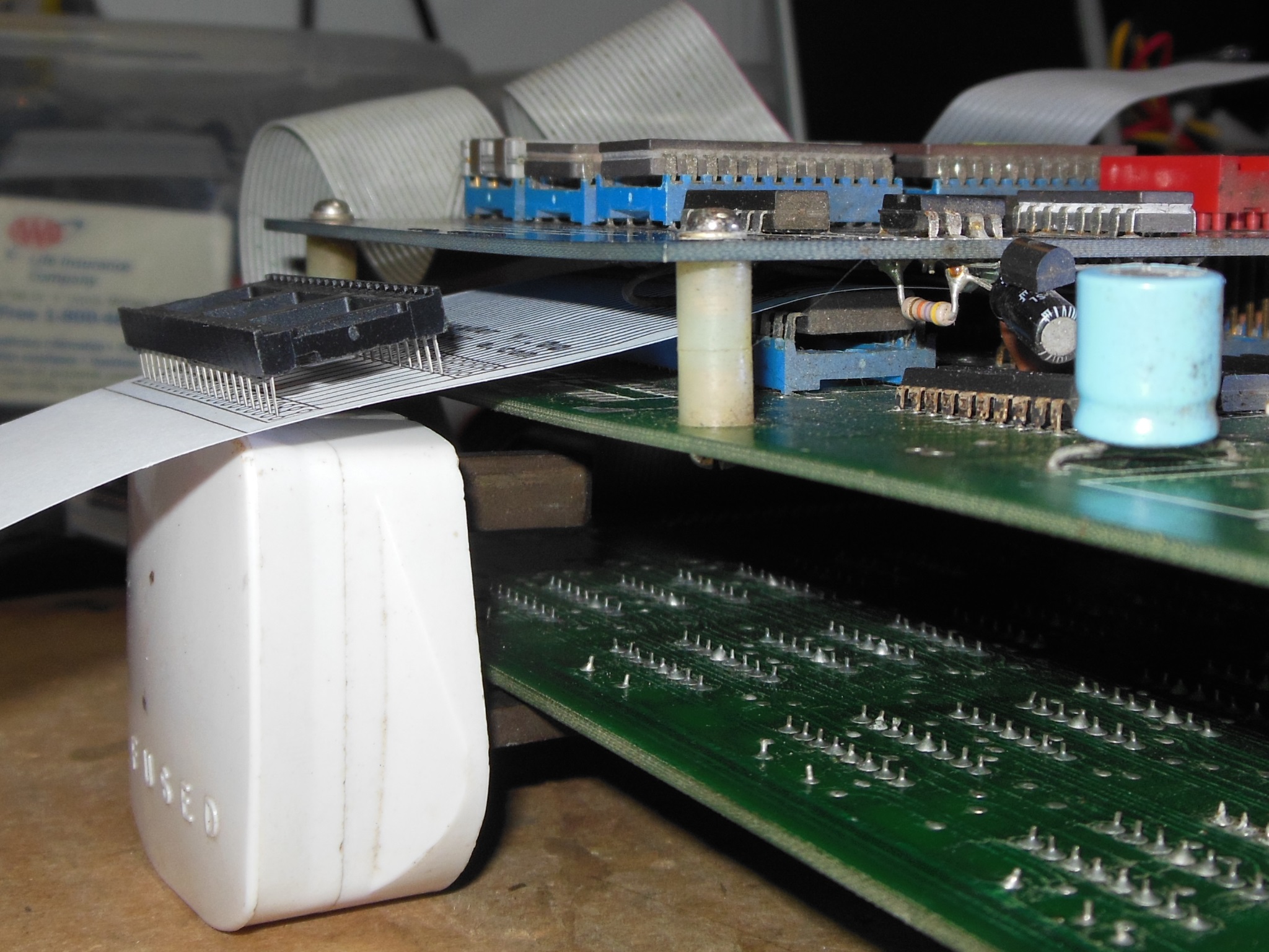
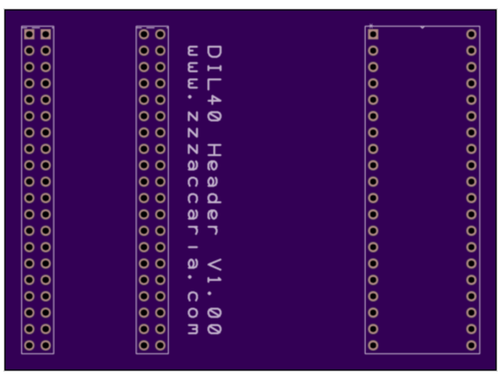
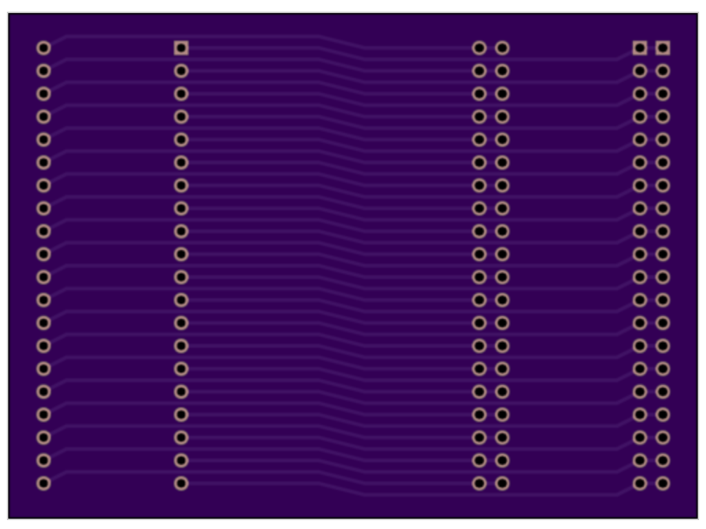
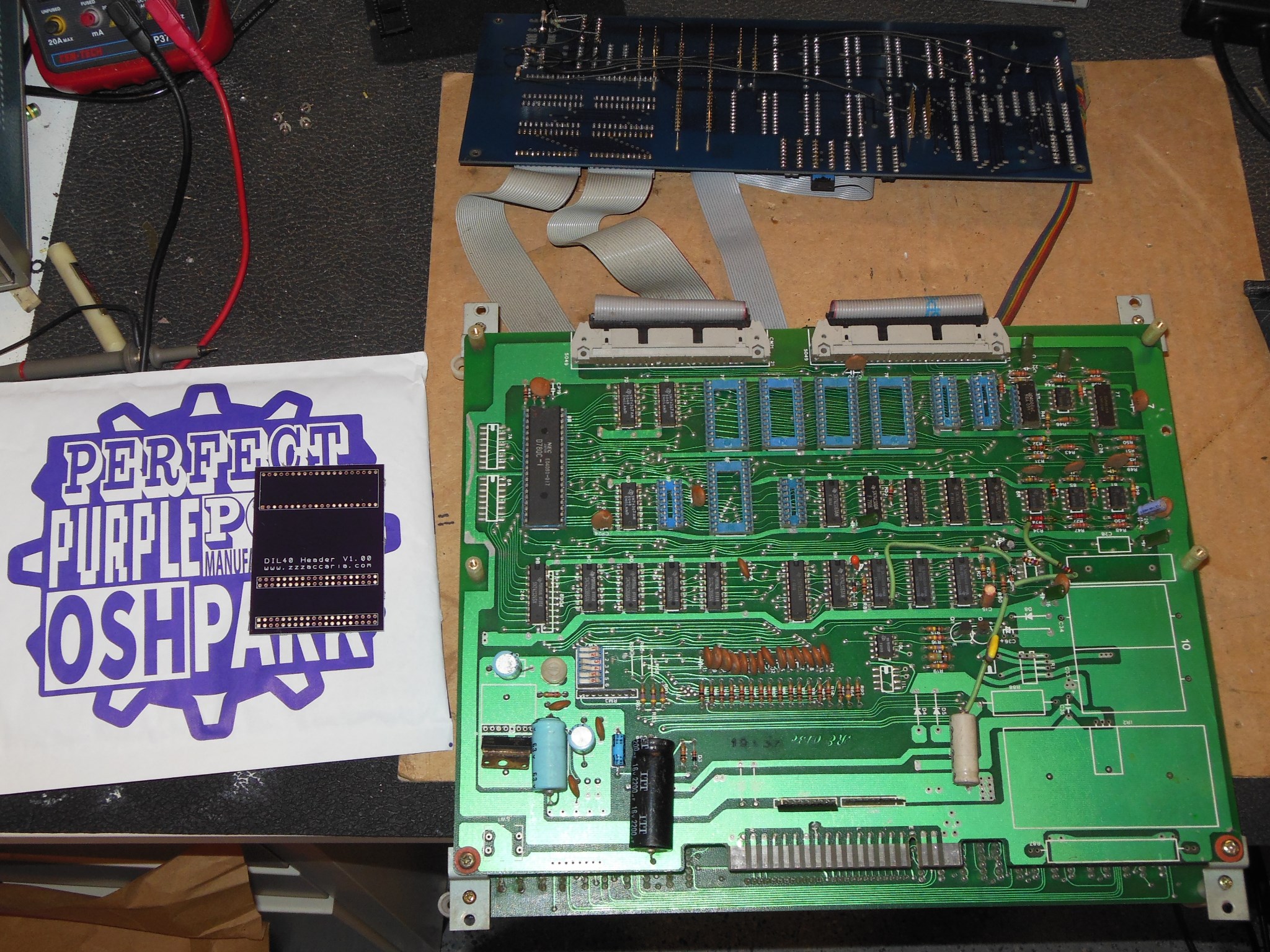
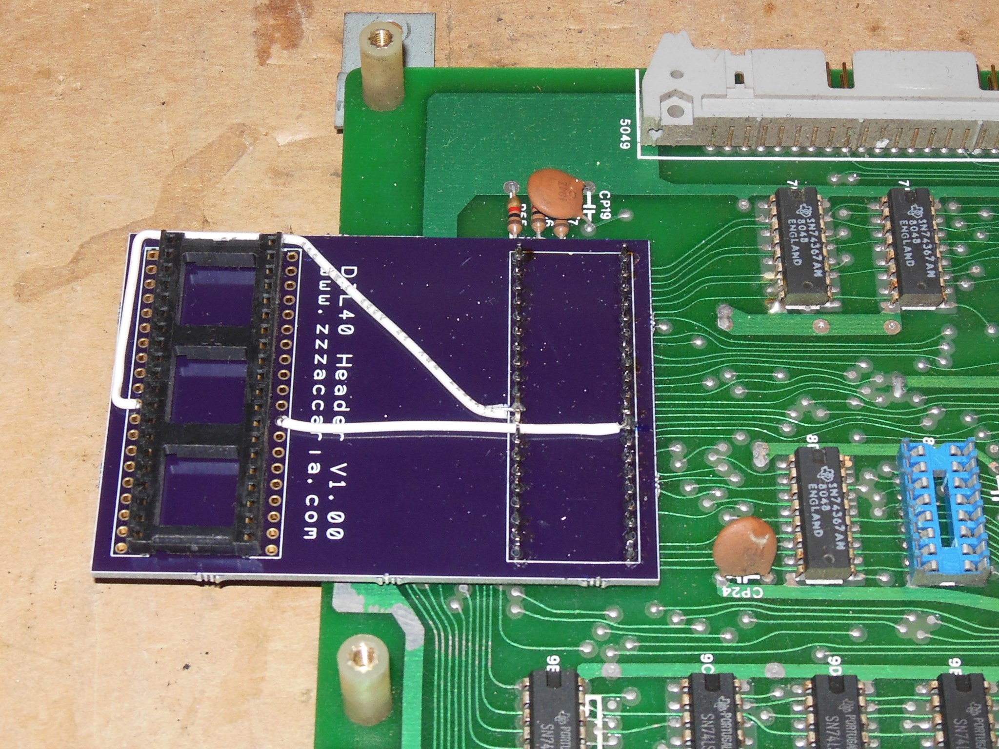
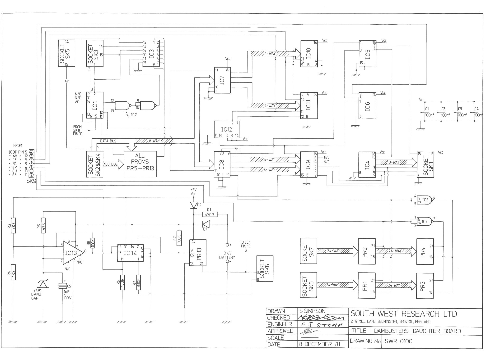
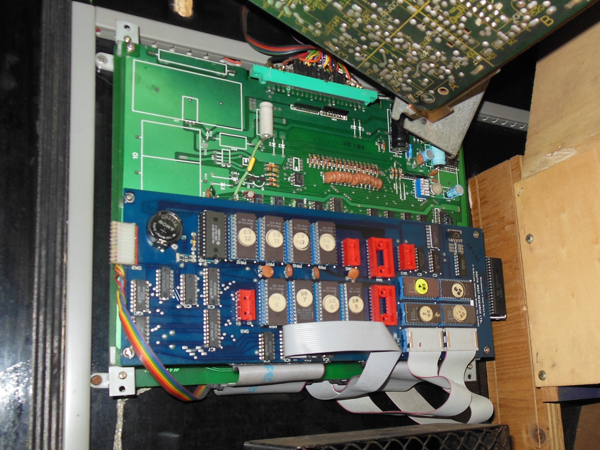
The SWR Dambusters game PCB consists of a cocktail Galaxians PCB set with a number of hacks'n'straps including a large daughter PCB plugged into various sockets on the top board. This design was problematic for repair because the Z80 was sandwiched between two PCB's and the cocktail PCB did not have the side test connector found on some editions so I couldn't attach the Arduino In Circuit Tester. The initial plan considered was to use an IDC DIL 40 plug and short length of ribbon cable to the ICT DIL probe header PCB. Unfortunately, the row order on the probe head would have been crossed thus I'd need to make a new PCB with the rows in the correct order. Since a new PCB was needed, I decided to make it all in one to move the Z80 out by a couple of inches verified with a paper plot template before ordering.
|
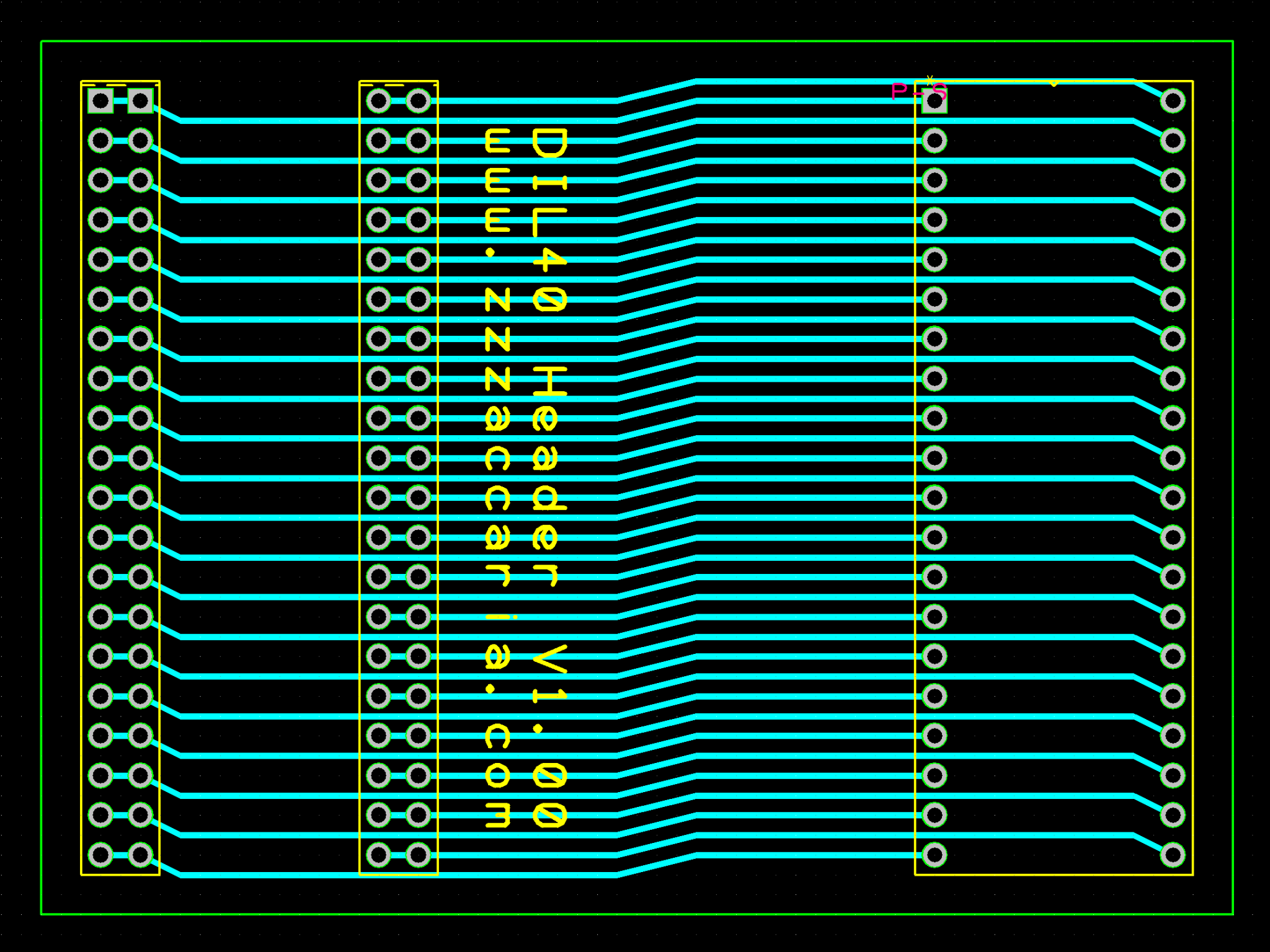
The design files and plots for ordering:
DIL40 Header PCB Design Spark source files
DIL40 Header PCB plot files
Alternatively, the PCB can be directly ordered from OshPark:
![]()
|
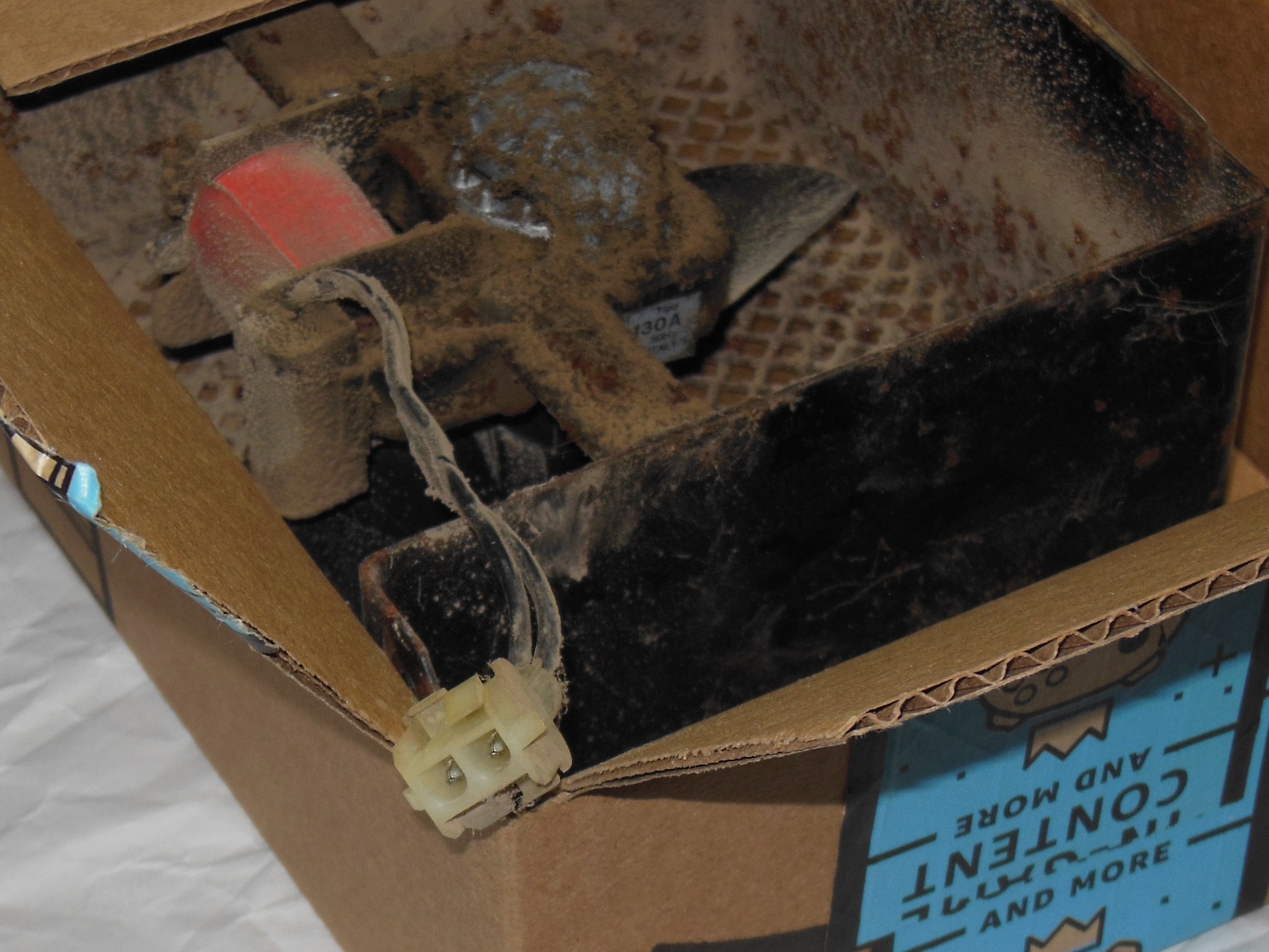
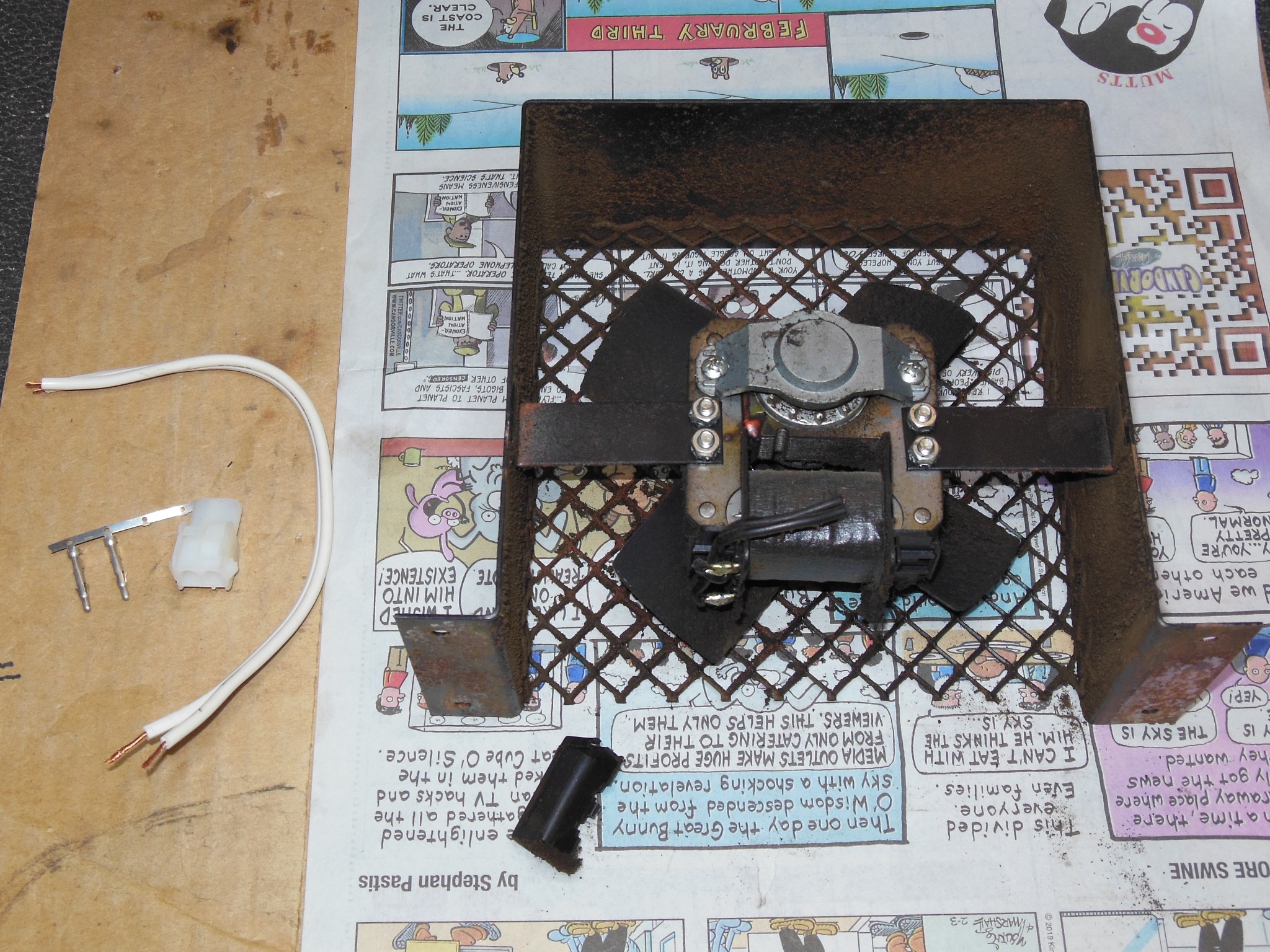
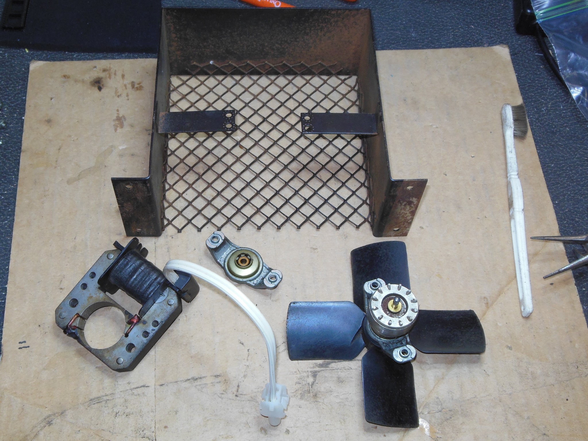
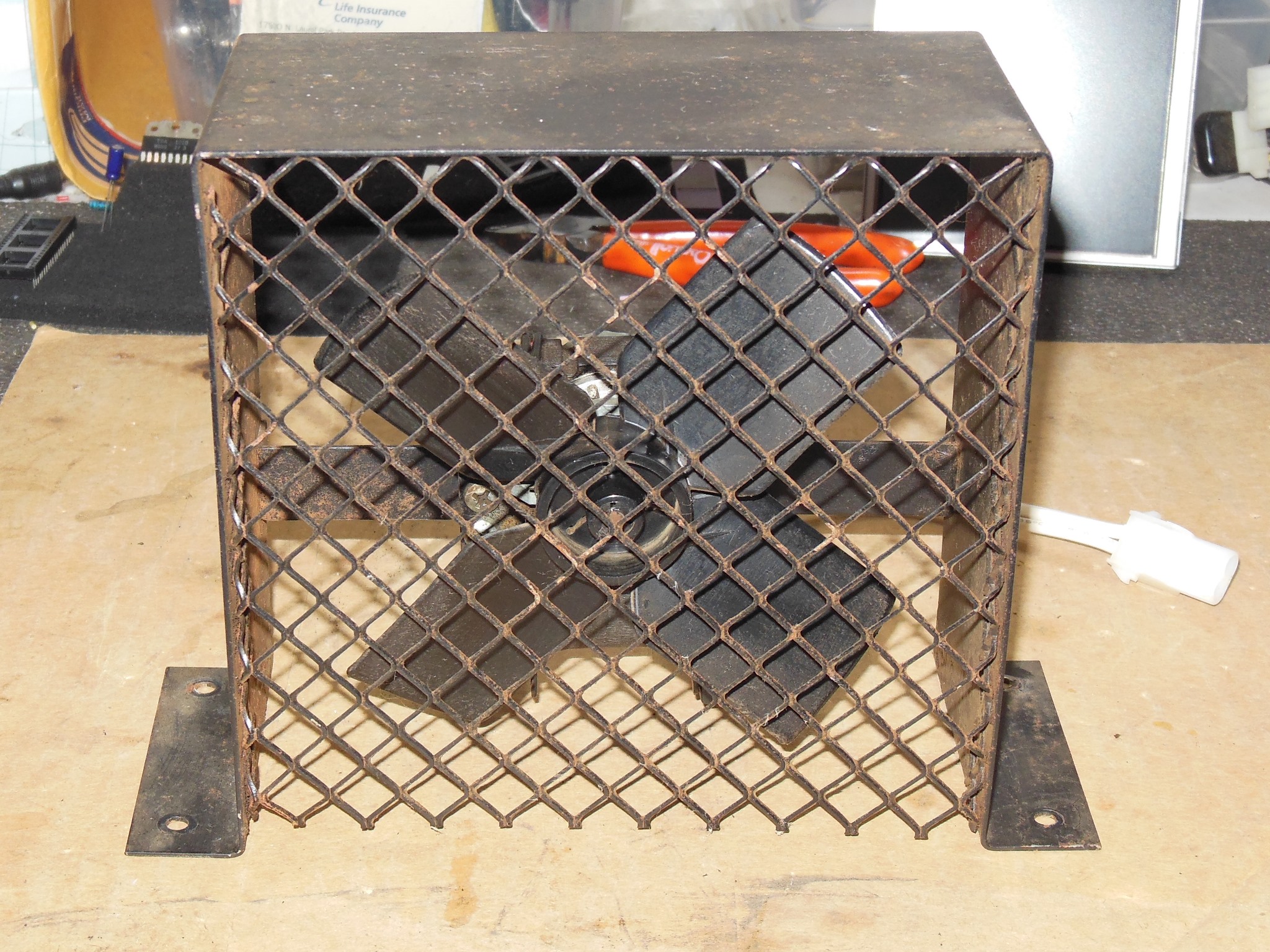
The fan was missing from the cabinet, so I picked out one of the best of the previously removed ones to restore. The connector cable was missing so I made up a replacement cable based on another example borrowed from another cabinet and stripped down the fan to clean and grease the bearings.
|
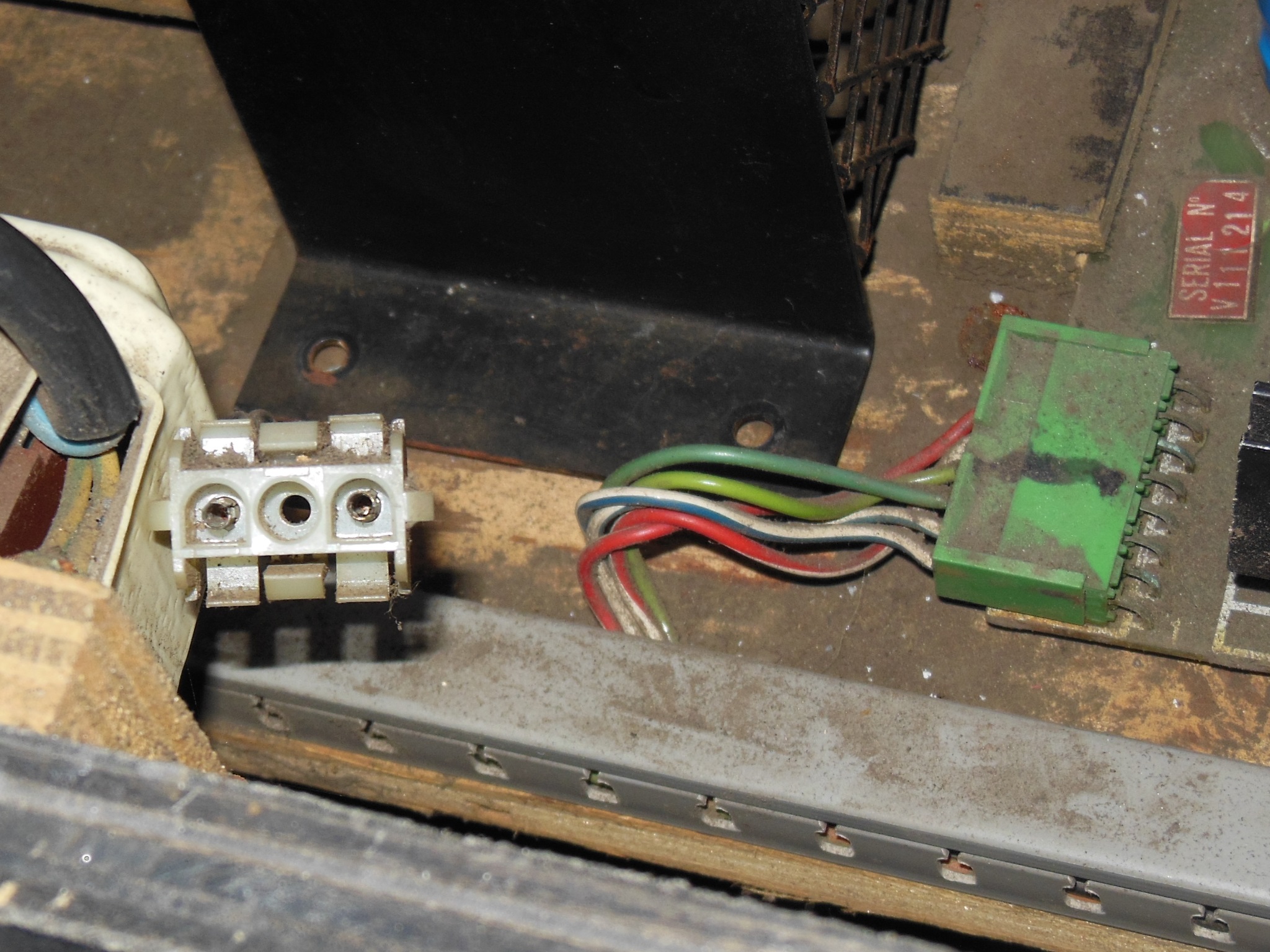
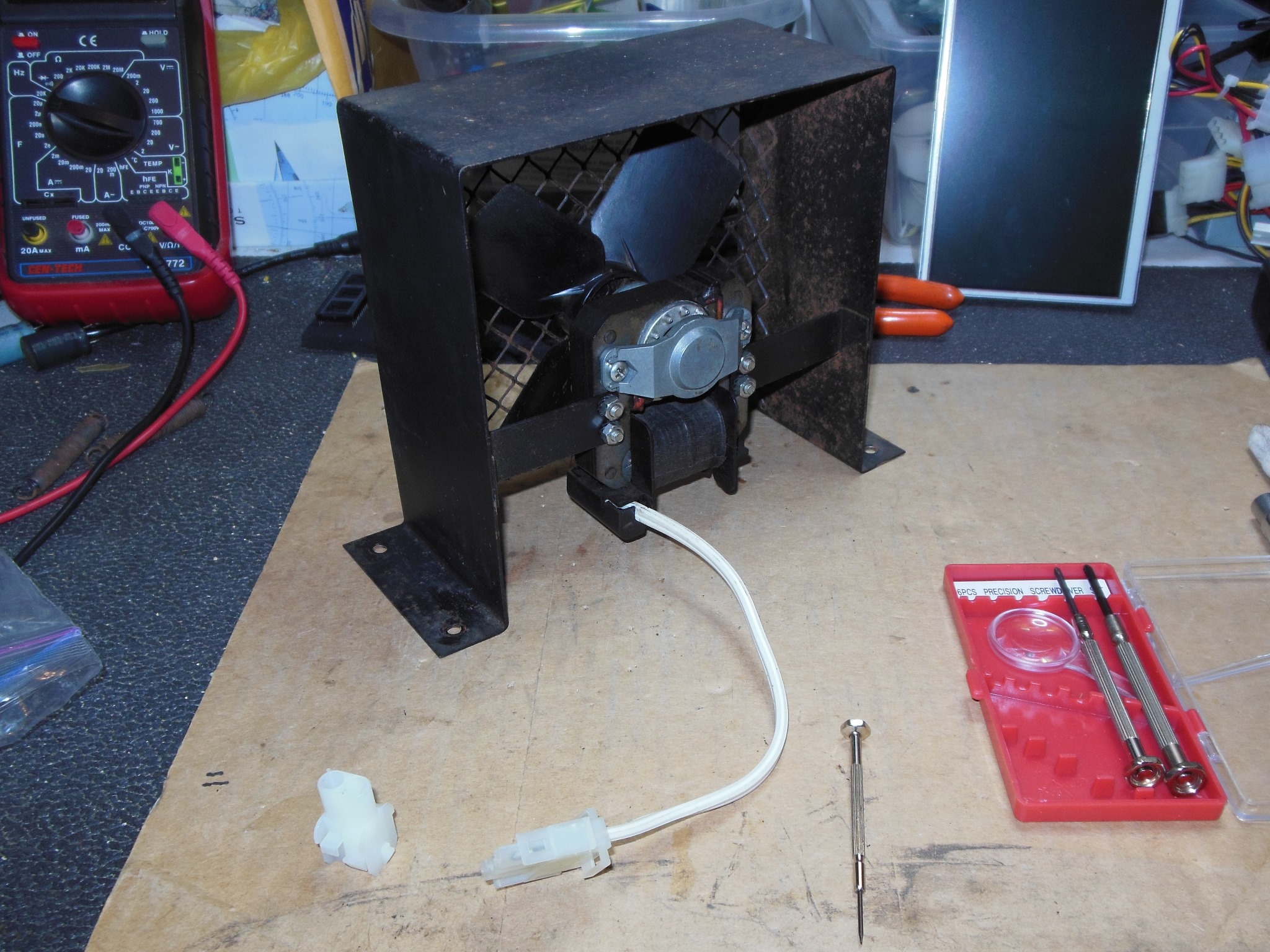
I'd not checked that all Zaccaria cabinets had the same fan connector - the example I borrowed came from another converted Zaccaria Quasar in the same artwork style so I hadn't expected the fan connector to vary but the one in Dambusters was a three-pin connector versus the two-pin I'd assembled. I had the three-pin to hand and was able to pop out the connector pins to go into the three-pin housing OK.
|
The non-polar capacitors arrived. These were intended for high quality audio applications but I surmised that the 15KHz line operating frequency was in the realm of reasonableness. I also noted the PCB had erroneous polarization marked for C561.

|
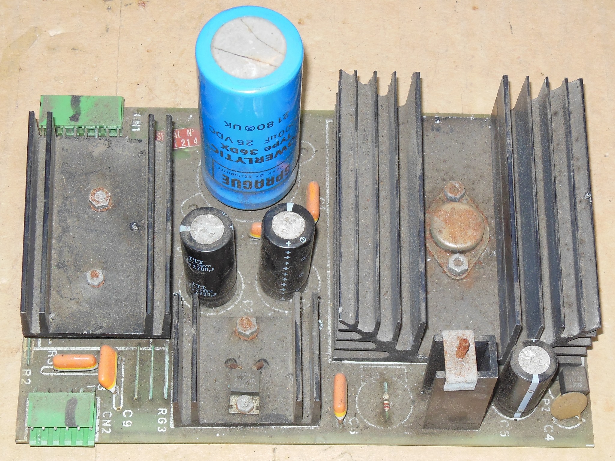
The 1B1126 power regulation PCB was removed and cleaned up. The capacitors looked OK so I left them as is for now.
|
A credit button bracket was fitted and wired into the 10p coin switch.

|
With most of the interior base components removed the interior was vacuumed out.
|
With all the internal components reassembled back into the cabinet the game was retested. The game PCB was still faulty, but the picture quality looked good.

|
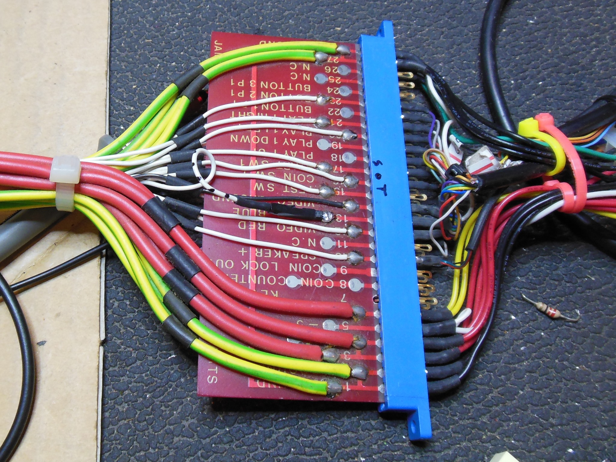
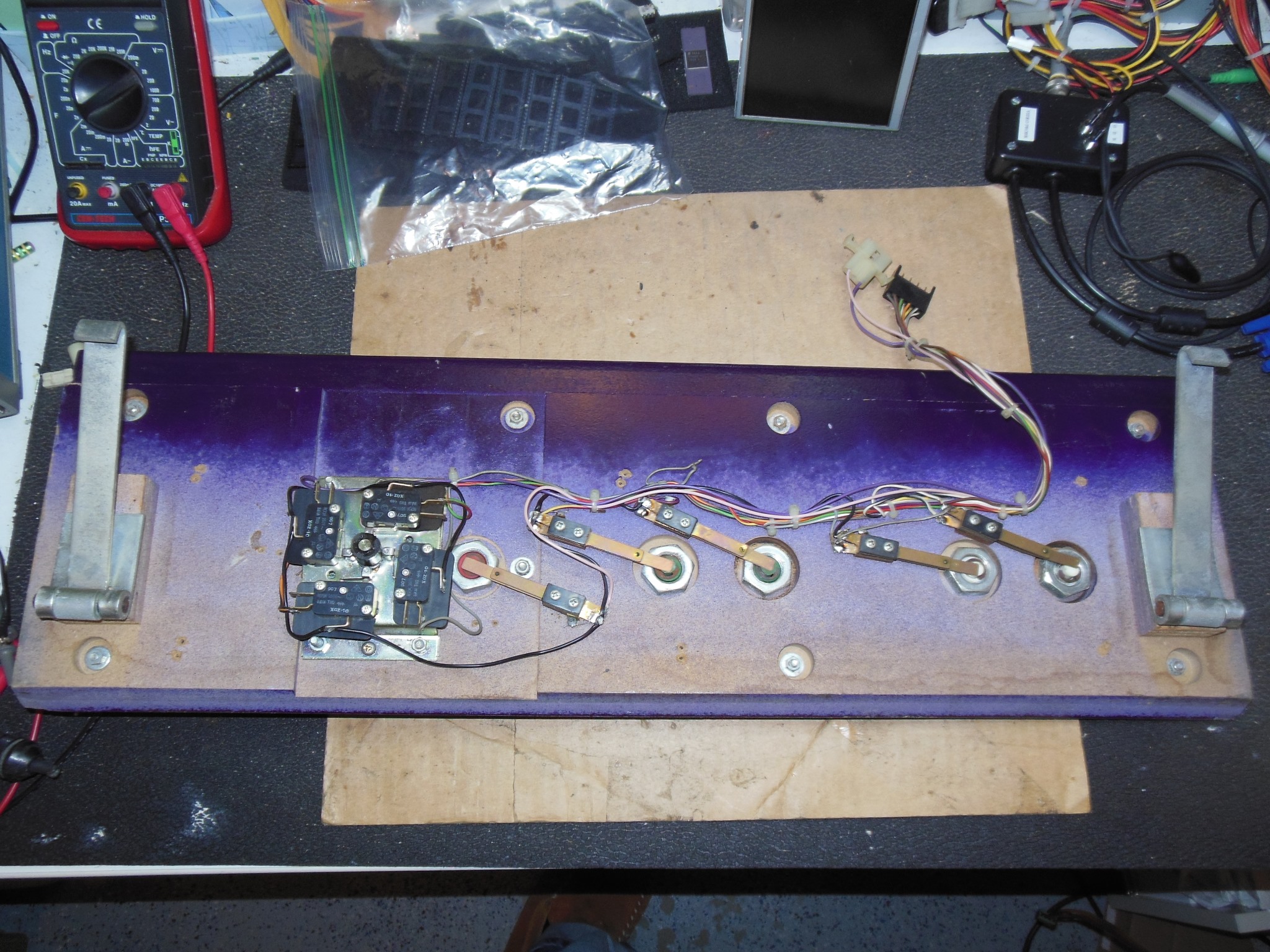
The additional input signals Dambusters needed over Quasar were neatly added onto a second connector to facilitate control panel removal. All the existing Quasar buttons were used except for one button that provided the hole for the four-way joystick.
|
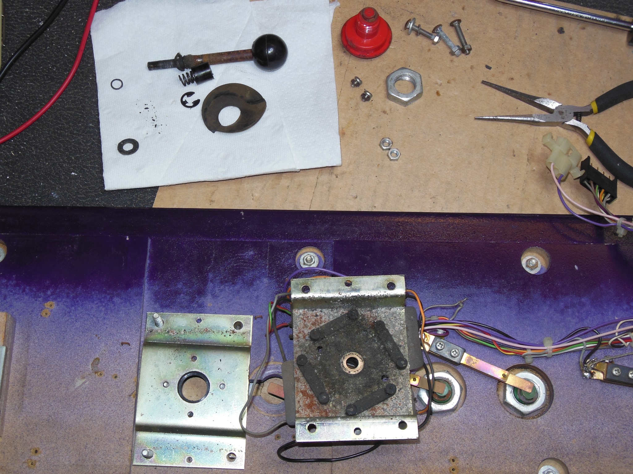
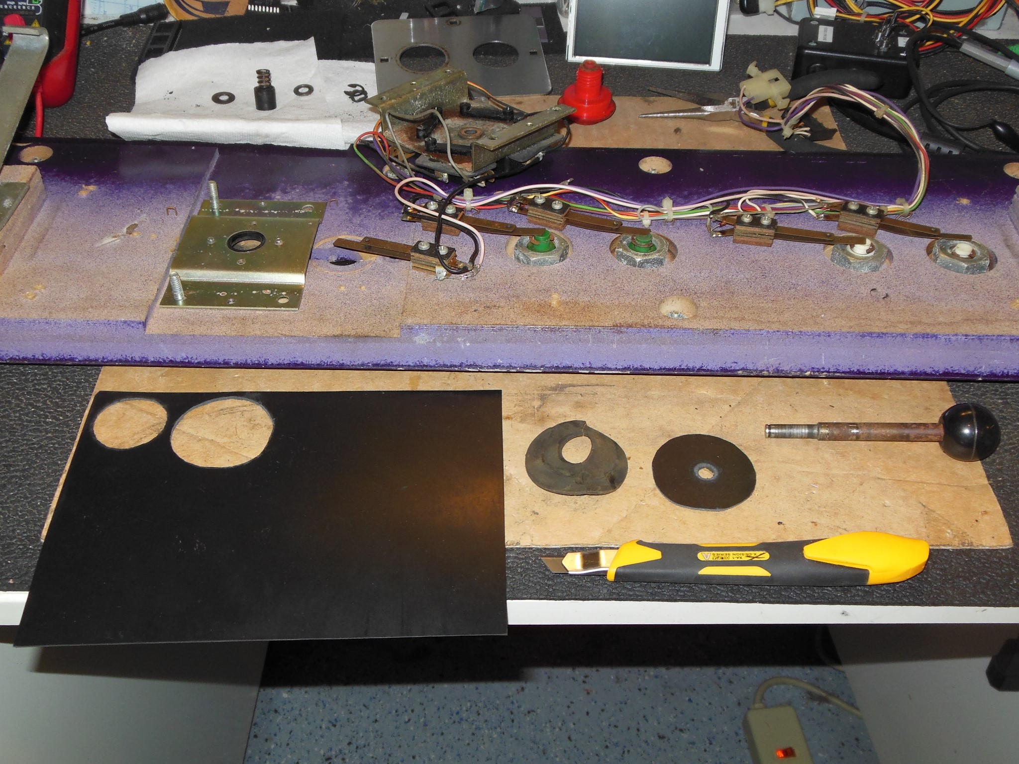
The joystick was removed & disassembled for cleaning & repair. The top dust cover was torn so a reproduction was made from a rubber sheet with a craft knife.
|
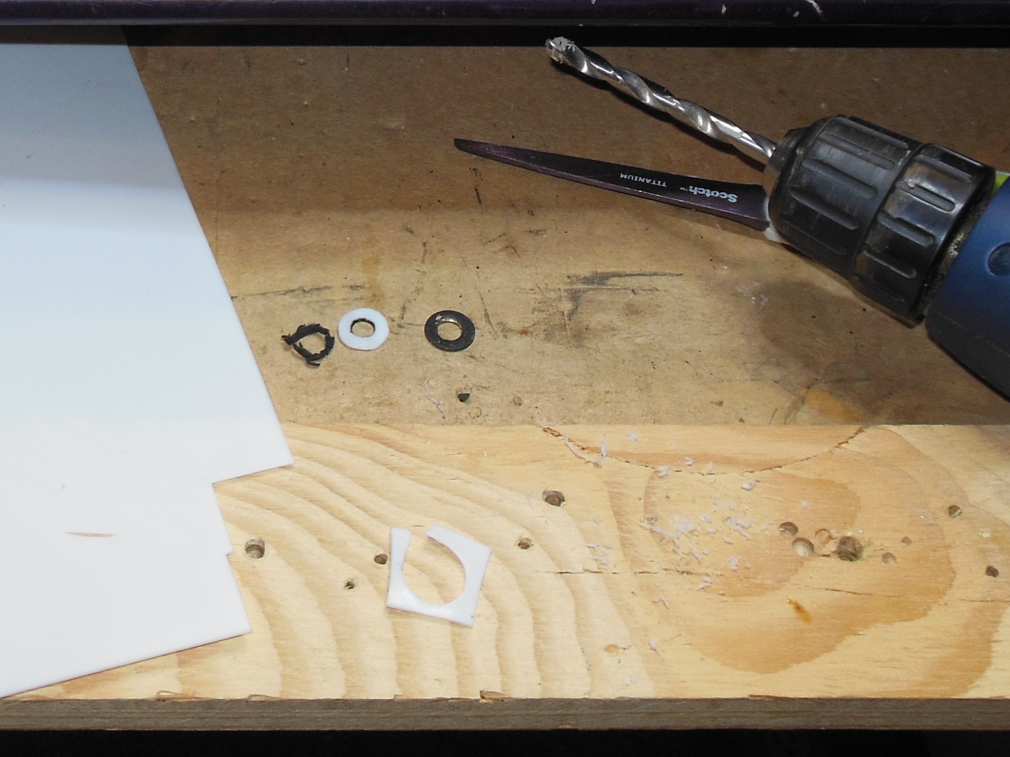
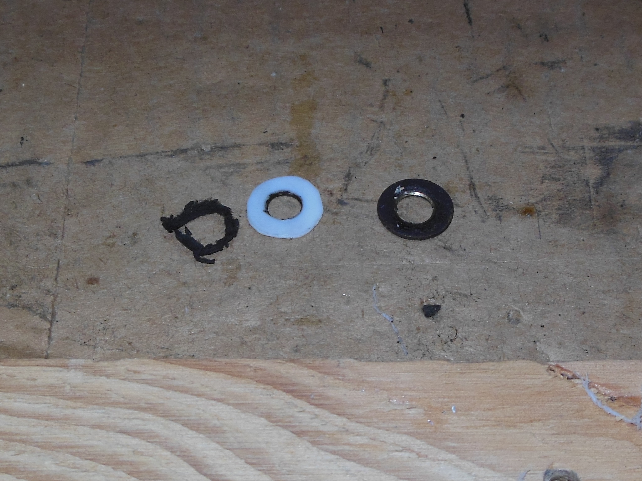
Between the shaft and the socket was the remains of a washer that likely gave the joystick a smooth tilt. A reproduction washer was made from a sheet of Teflon and the joystick reassembled. The buttons looked pretty clean, so I left them as is and just cleaned the leaf contacts with a strip of cardboard.
|
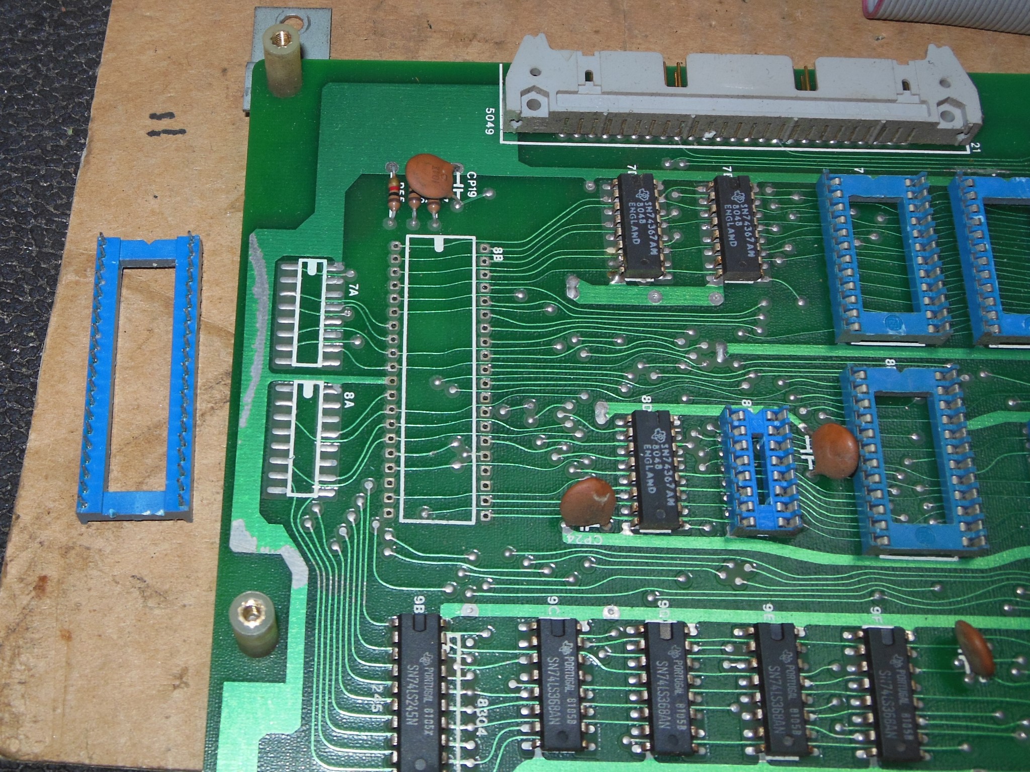
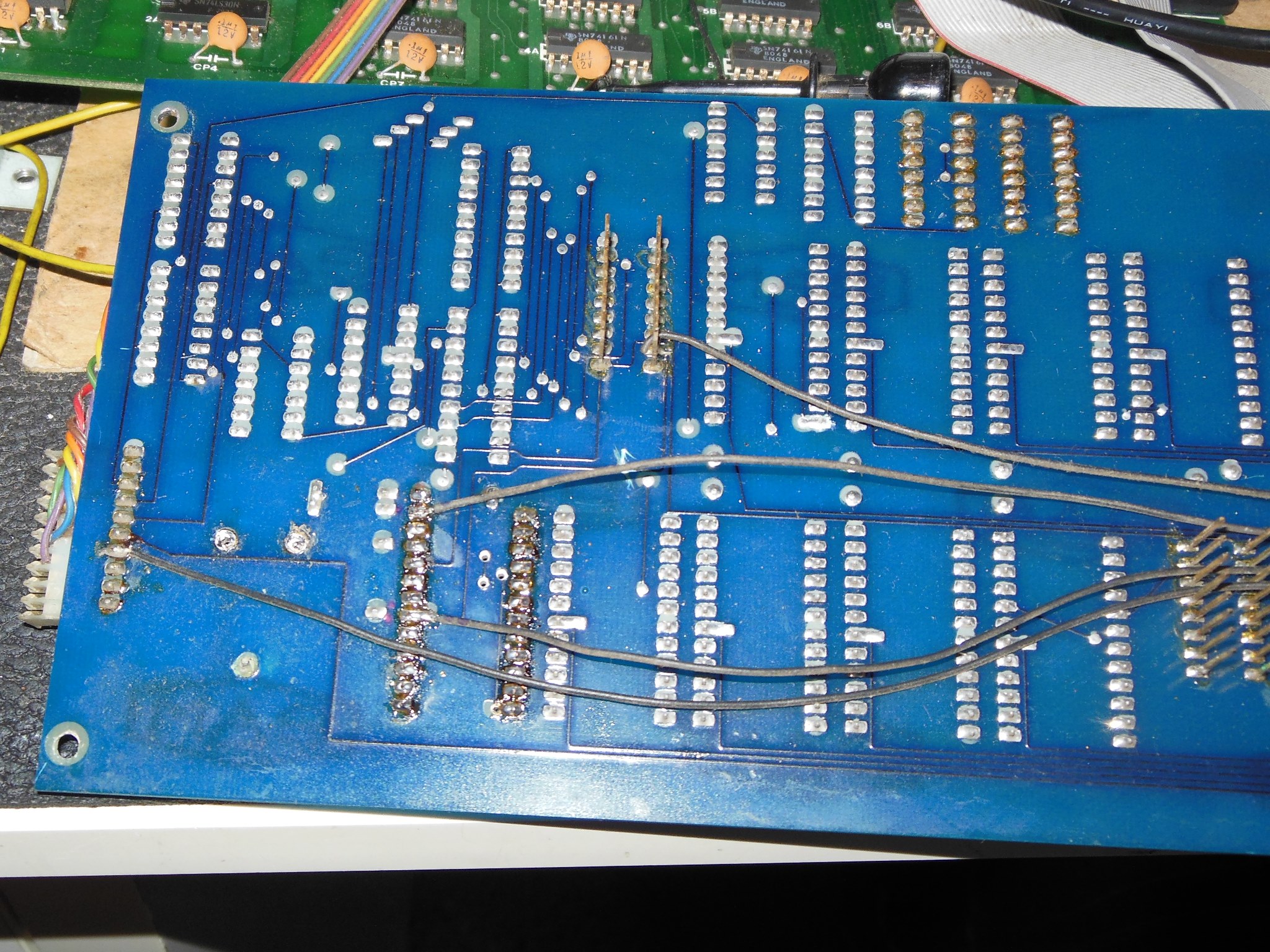
The DIL40 header PCB to move the Z80 CPU out from underneath the daughter PCB arrived and appeared correct. There wasn't enough clearance to allow the header to plug into the existing Z80 socket and if the header became loose or detached the whole daughter PCB would need to be removed to put it back, so I decided to risk removing the socket entirely to permanently hard solder the header onto the main PCB. Thankfully no IC's would be covered by the header PCB.

|
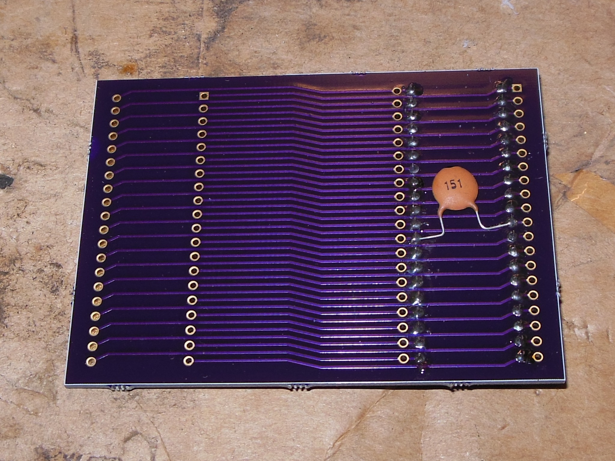
The DIL40 header PCB hadn't been designed specifically only for the Z80 CPU and thus it needed a couple of small modifications to tailor it. The first was the addition of a power coupling capacitor on the back to help with power noise as a result of the longer power traces and the second was added power wires to improve the power distribution in addition to the PCB tracks (that were thin signal tracks).

|
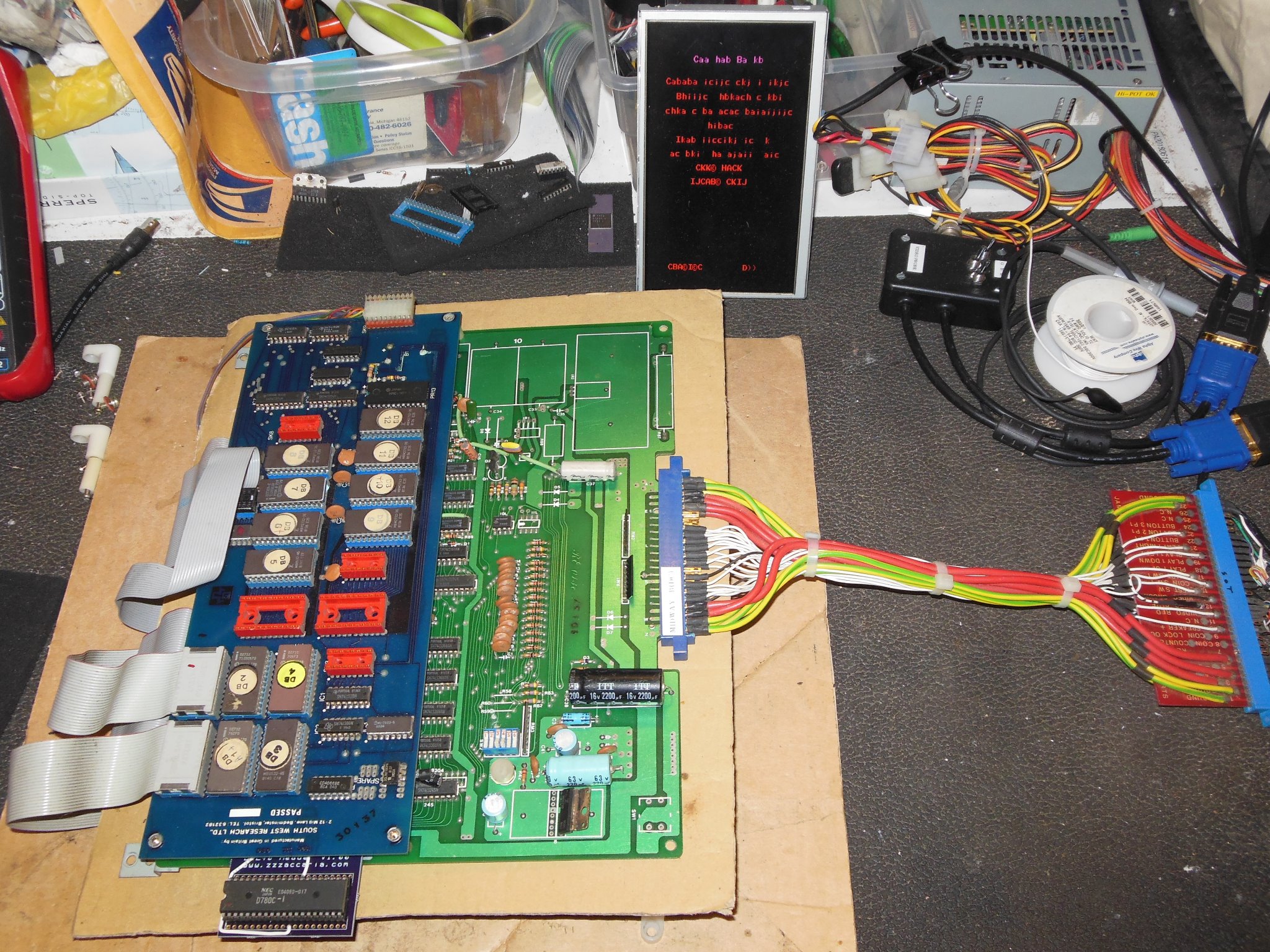
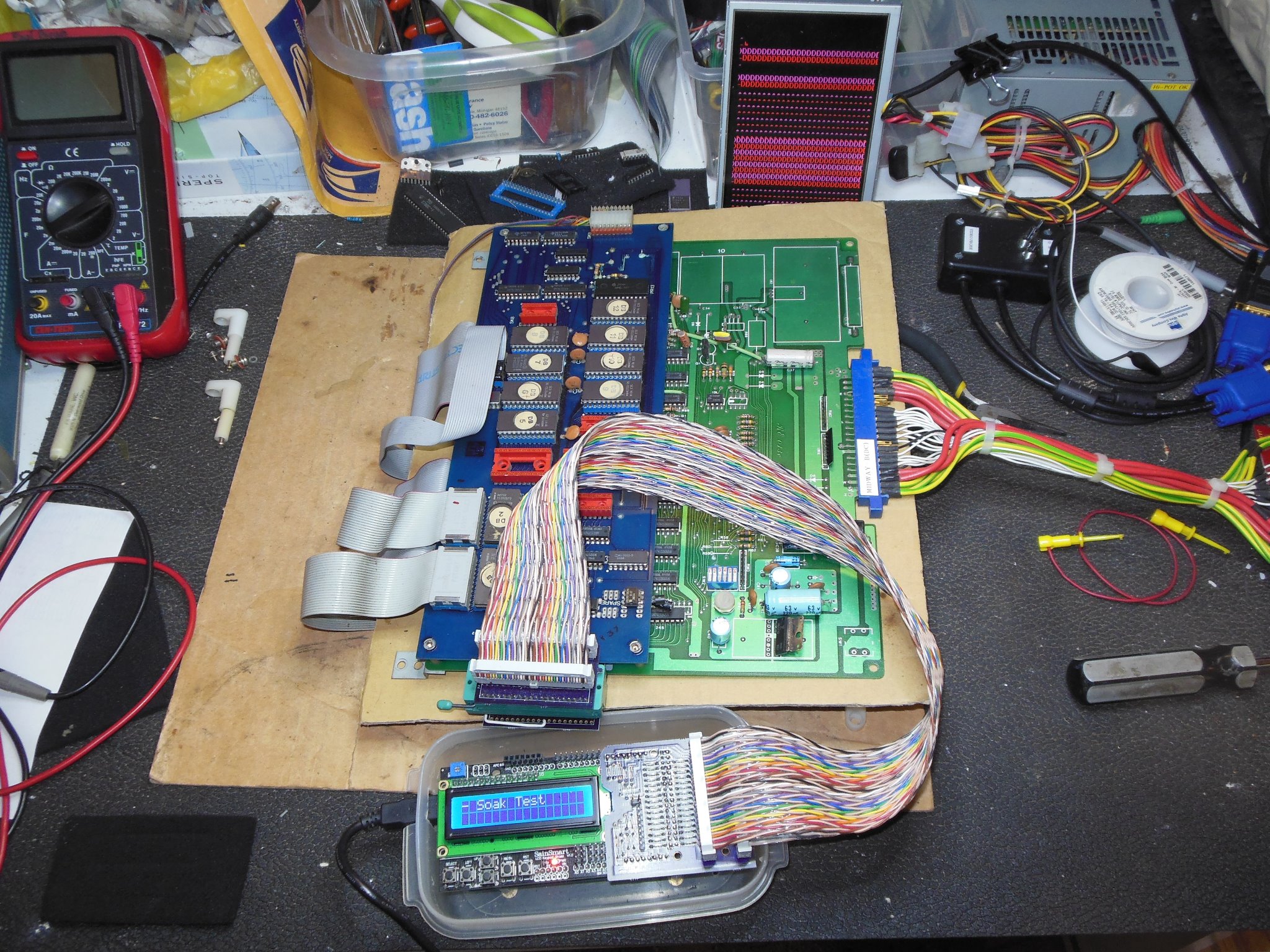
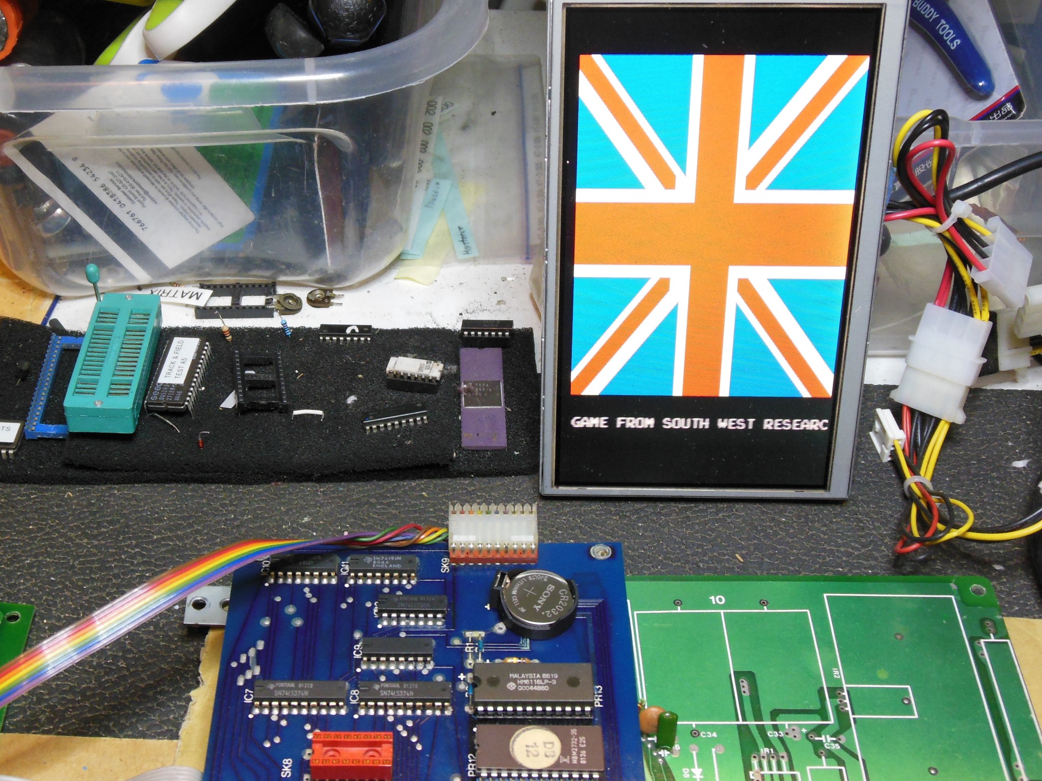
After checking for an obvious short, first power on yielded a running game in no worse shape than without the header. Adding Dambusters to the Arduino ICT was a bit more complicated than other games because SWR employed a rudimentary copy protection scheme that swapped the address & data lines on some of the EPROMS. With that taken care of the ICT was able to test out the game. The strap to turn off the watchdog on Galaxians hardware was obscured by the daughter PCB so I added a small wire loop from the pull up resistor to the IC pin on the underside to support the strap.
|
The ICT reported "E: 5F d800 90 d0" indicating IC 5F (2101) was bad. Replacing 5F
fixed the RAM test failure. All other tests passed OK. The text characters were still
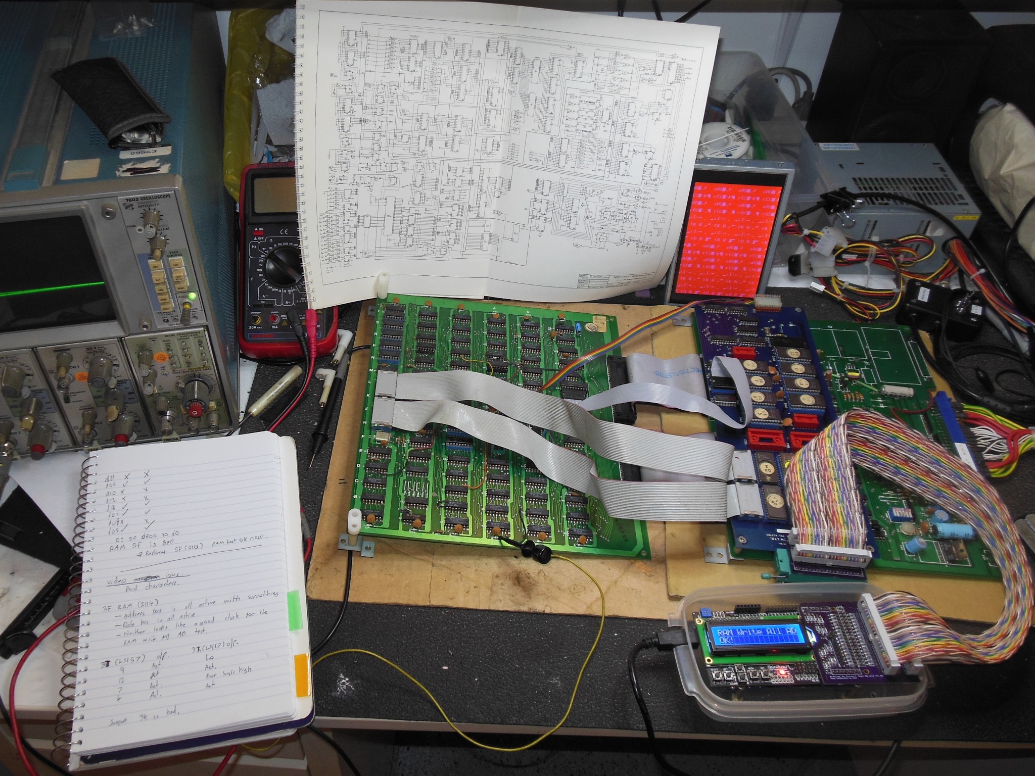
bad. Starting out at RAM IC's 3F & 3H (2114) with a scope confirmed all the address &
data bus was active. Moving downstream to the inputs & outputs of IC's 3K & 3J (LS157)
found:-
IC 3J (LS157) output pins:-
|
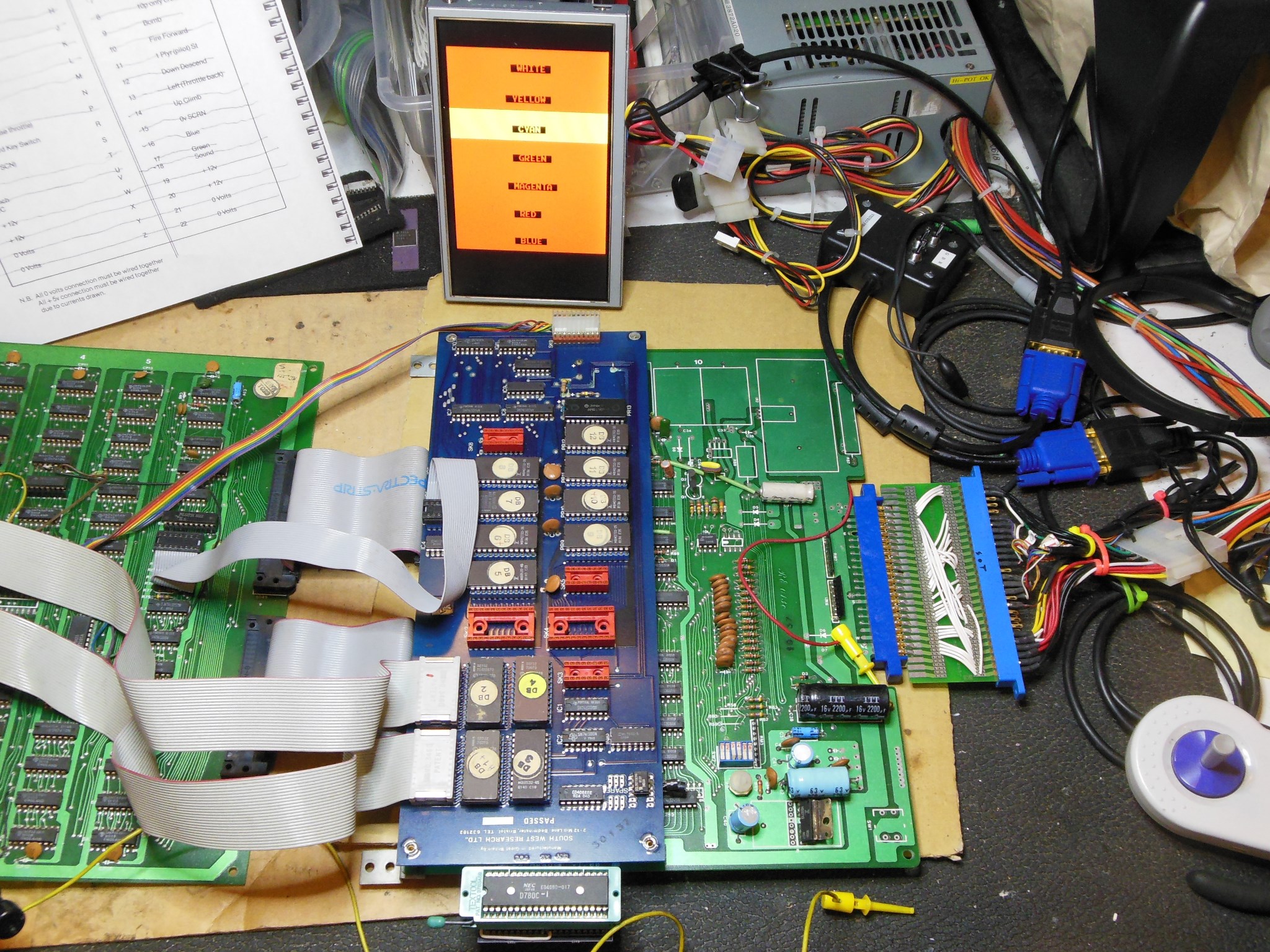
The next board fault to address was the bad colours. Since I was using a slightly modified Midway Galaxians JAMMA adaptor both the colour outputs and control inputs were wrong for Dambusters. To be able to see the correct colours and play test the game I decided to make up a dedicated Dambusters JAMMA adaptor. With all the inputs now populated on the JAMMA adaptor I was also able to enter the game self-test mode and utilize the built in colour test screen to investigate the colour fault.
|
The colour display showed incorrect colours and poor colour depth. Starting at IC 6L (PROM socket) input pins:-

|
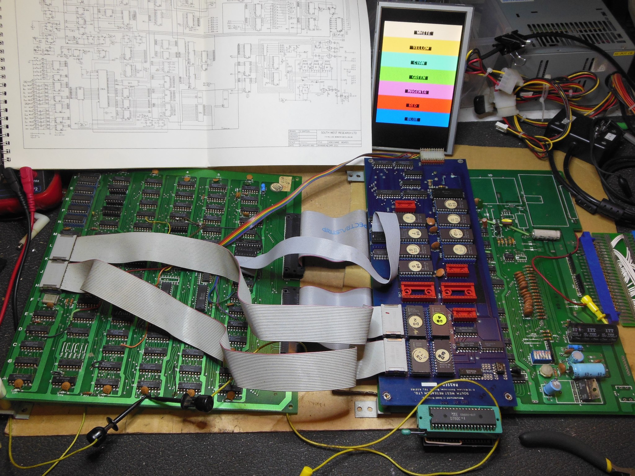
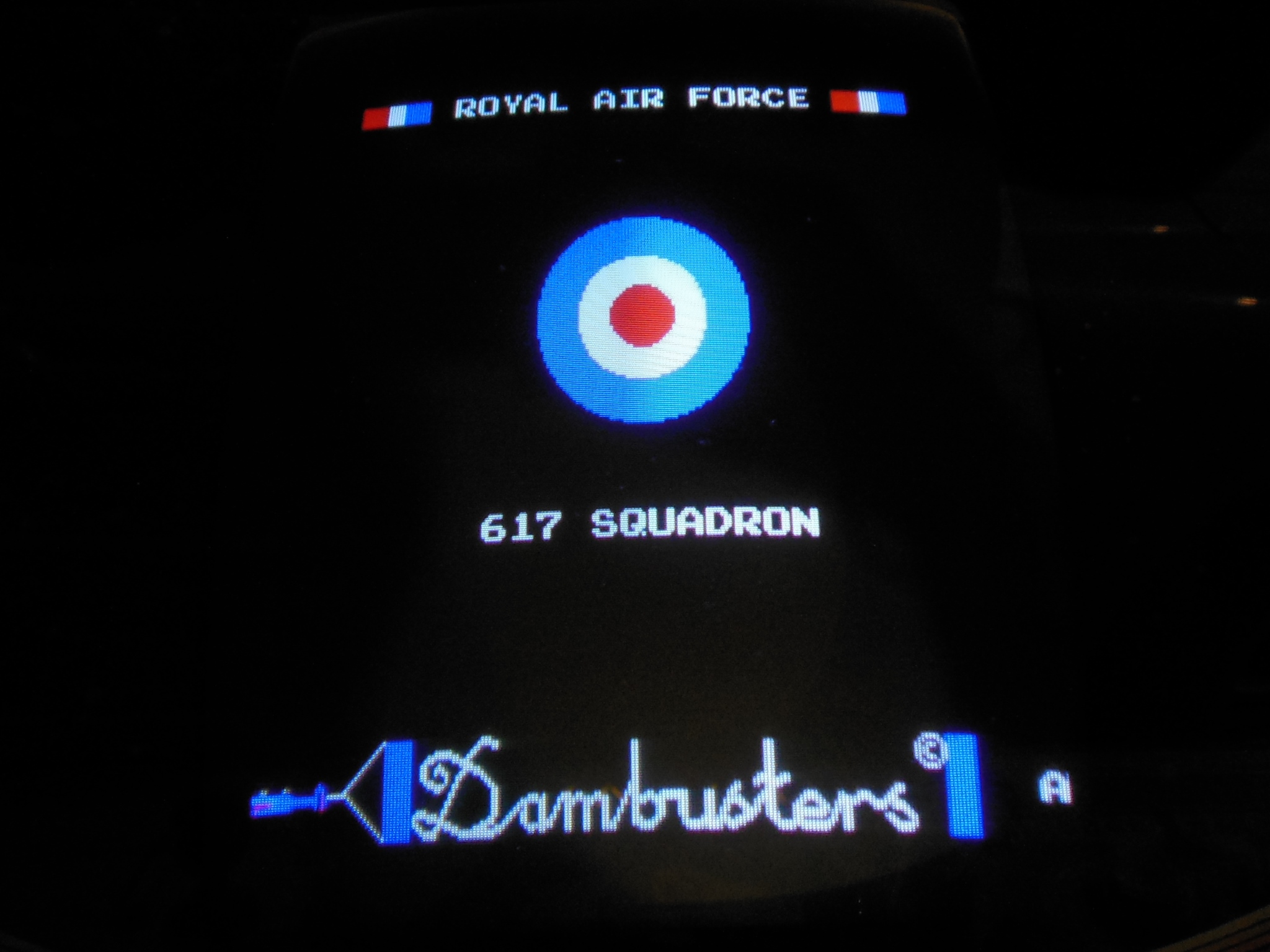
With the graphics now fixed I was back to where I was in the late '90's with this game. The high score table was corrupted, and the game was unplayable because the fuel ran down prior to take-off so the bomber crashed immediately. To quote the SWR manual:-
This is done prior to the board or complete machine leaving the factory. It puts the
coin counters, total taken and hours the machine is on back to zero, (test 2).
If the machine requires initialization at any time in the future, please contact South West
Research Limited.
Back then I'd felt that there had to be some hidden method that allowed the battery RAM to be initialized outside the factory but nothing had yet been published. However, MAME has the game implemented and it has no apparent problem with the initial state of the RAM contents so maybe an all-zero starting point would be OK?


|
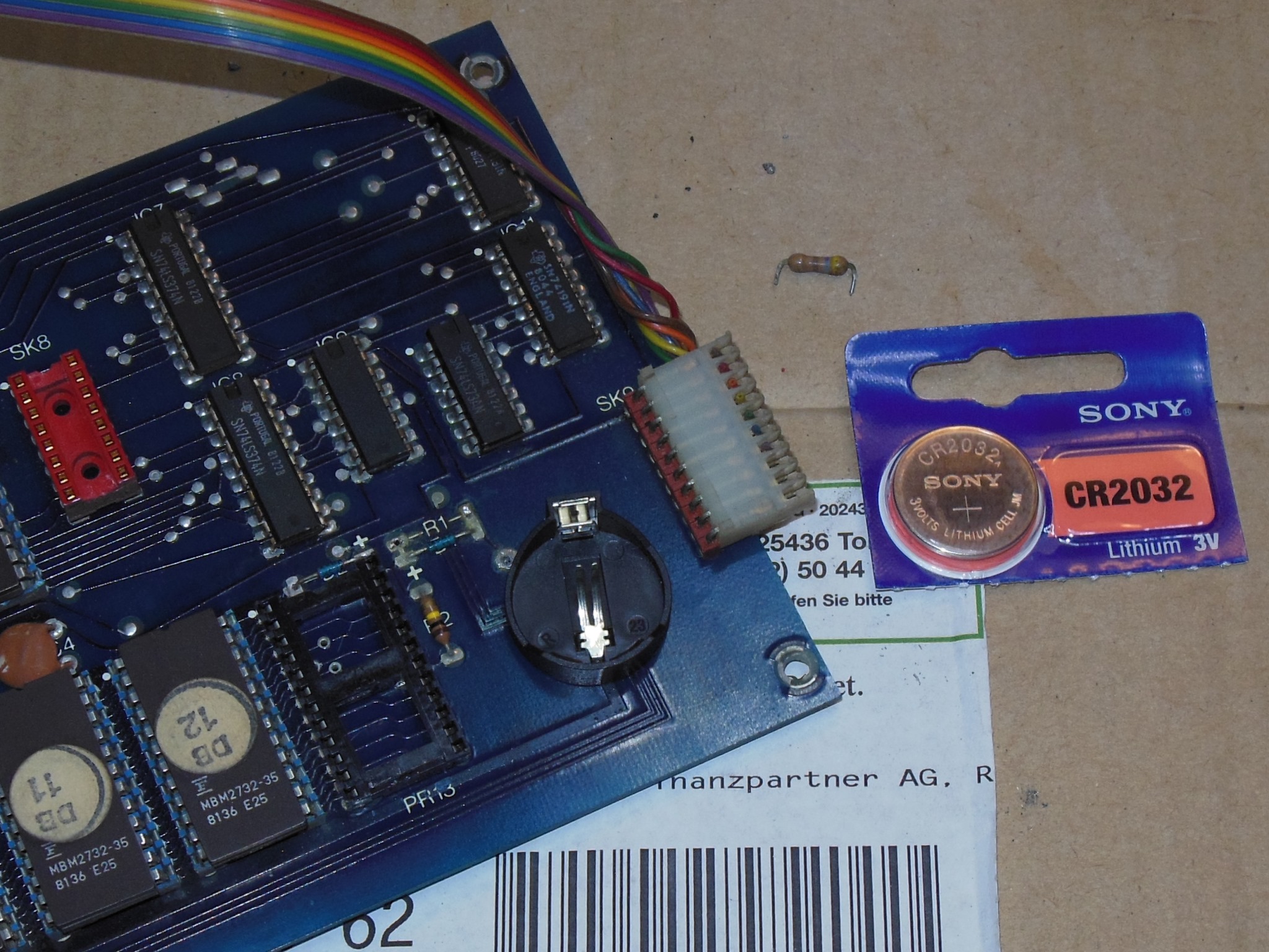
Before figuring out what should be in the battery RAM the plan was to replace the discrete external NiCad battery and CMOS RAM with a Dallas all-in-one Lithium battery RAM module. The replacement was straightforward since the RAM was already a pin compatible CMOS 6116, only needing the +5V diode removed since the battery RAM handled everything internally. With the Dallas installed the game ran no worse than it had with the 6116 (still not correctly).
In terms of battery contents I used the Arduino ICT to set all the battery RAM to zero and then retried the game only to find no change - still corrupted high score table and immediate fuel run down & crash in the game. The SWR manual showed some management circuitry on IC PR13 pin 18 (CS) that was no longer be needed with the Dallas installed so I bypassed that circuit to allow the CS line to be directly fed. There was still no change after an ICT RAM clear. Now it was coming back to me. Back in the '90's I'd used the Fluke 9100 to clear the RAM and remembered hitting the same problem of a clear to zero not working to recover the game :(

|
I noticed the reset signal was tapped from the main PCB and wondered if that could be bad causing the RAM to be corrupted on power transitions. Checking on the scope showed the reset line transitioning with no obvious issue.
By this time, I was suspicious of the Dallas RAM itself. To verify the battery RAM contents I added an option to the ICT to allow RAM CRC calculation. After a "RAM Check" (to load a known pattern) and "RAM CRC" a power cycle did indeed result in CRC mismatch and I declared the Dallas battery flat.

|
I had no more Dallas RAM in stock and doubted that I could find a reliable source for them so came up with a new plan restore the SWR battery circuit back to original and refit a 6116 low power L-version for battery backed applications along with a CR2032 coin cell replacing the original NiCad battery. Since the coin cell is not rechargeable I left out the charging resistor R1 (470R). With coin cell fitted the VBatt was 3.10V and VRam was 2.62V. Testing with the Arduino ICT confirmed the RAM was working and preserved across power cycles. After clearing the RAM the game finally booted and played OK. Over the next few days I checked the battery voltage to confirm it would last at least a few days (in fact the battery was still OK through to the end of the show).

|
As previously noted, MAME didn't do anything special to initialize the game RAM and gives the same score display as seen on the game PCB with RAM cleared to zero. Whilst clearing to zero seems to allow the game to run and new valid scores to be added, it did look like the RAM contents were initialized to something specific at the factory.
A future project would be to decode and disassemble to game code to look for an Easter egg factory initialization method.

|
The game PCB ran without issue when tested in the cabinet.

|
The game PCB was installed back into the cabinet and the game ran for several hours with no further issues. In colour test mode, yellow seemed a bit on the green side and cyan a bit on the white side but I decided to leave as is for the time being (a game PCB anomaly since it displayed this way on the bench).
|
A final wipe down with a damp cloth cleaned up most of the dirt and scuff marks just in time to make this year's show.