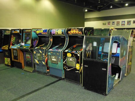


|
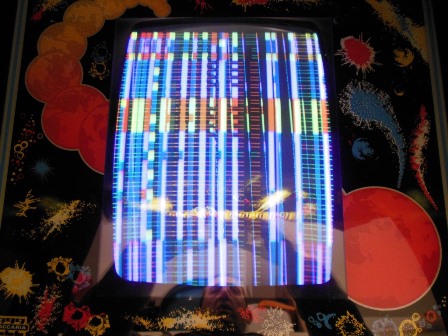
Pre-show testing showed no issues and the game was submitted into the show. However, the picture lost vertical sync and began to roll after a few hours. I tried swapping daughter boards with Astro Wars but even a complete swap of all of them didn't fix the roll. It was withdrawn into the backroom before the show opened.
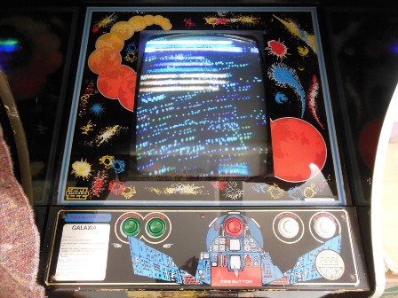
|
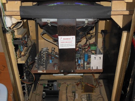
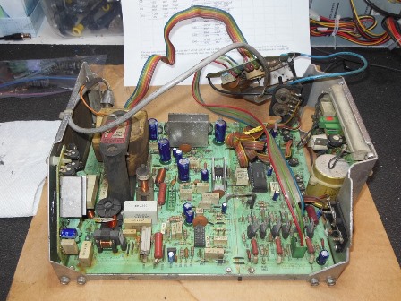
Retesting confirmed that the picture was still rolling as it had been at the show :( By this time I'd had enough of the MTC-90 chassis having been unable to keep them working reliably for long periods or provide anything more than poor picture quality. Despite a significant investment already made in spare parts I decided that it was time to retire all three (Astro Wars, Galaxia, Sea Scare) of my MTC-90 chassis at their next failure :(
The project to replace the MTC-90 chassis with a later MTC-900 chassis, preserving the
original wiring, CRT & frame unhacked, is documented on its own page:-
Hantarex MTC-90 to MTC-900 Conversion

|
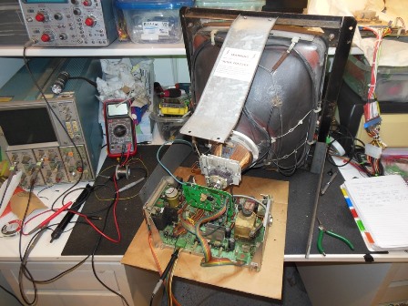
Since I'd run out of MTC-900 chassis configured for "FB" CRTs I needed to convert
an "S4" chassis. The project to do that is documented on its own page:-
Hantarex MTC-900 "S4" to MTC-900 "FB" Conversion

|
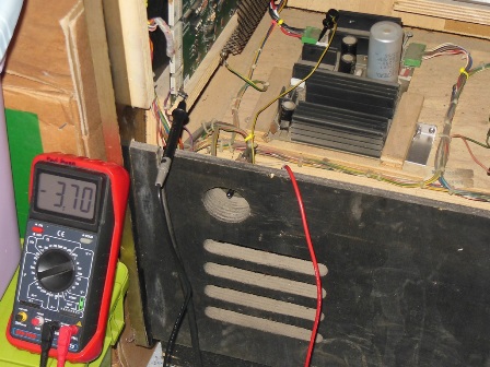
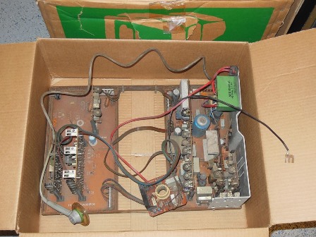
During testing with the original MTC-90 the game stopped booting. Checking out the power supply revealed that the -5V rail was reading only -3.70V indicating a problem with the 1B1126 power regulator board.


|
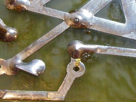
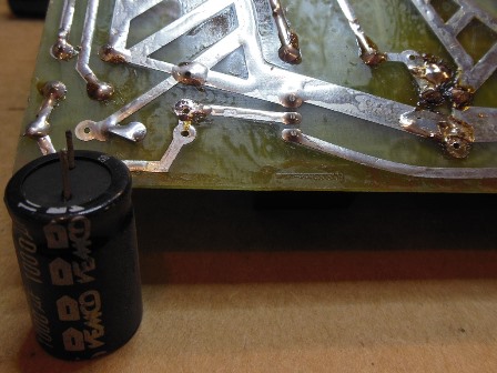
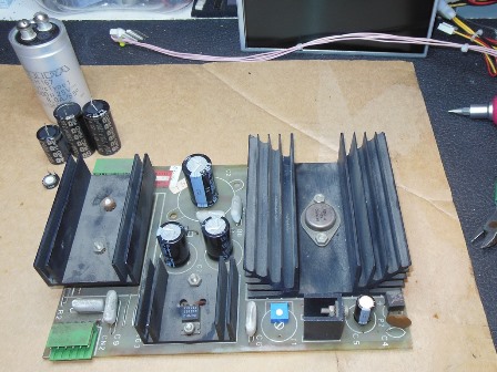
On the bench the 1B1126 power supply board had several loose capacitors due to many dry solder joints on the board. Since I needed to reflow all the capacitors I decided to cap kit the whole power supply.

|
The cap kit for the 1B1126 also has a voltage adjustment pot to replace the fixed resistor. The joints were so dry that capacitors could be pulled out without de-soldering. With new caps in the game booted up fine :)
|
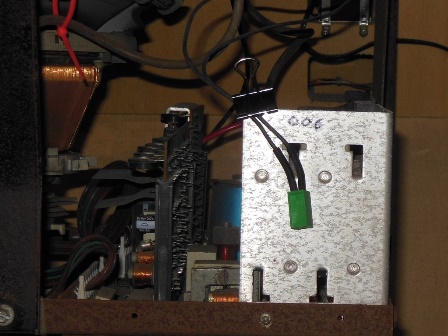
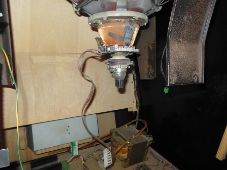
Before removing the MTC-90 I swapped over the degauss connector to a MTC-900 one since that's a bit easier with the chassis in to use to hold the connector in place.

|
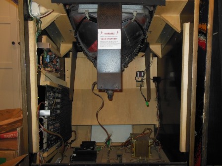
With the chassis out the yoke connector was changed over to an MTC-90 one. Unlike the MTC-90 in Astro Wars this cabinet had a slightly different frame with slots instead of holes to hold the original chassis. The L-brackets for the MTC-900 plate still fit OK, however.

|
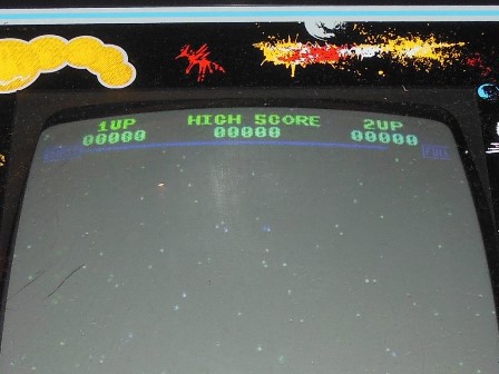
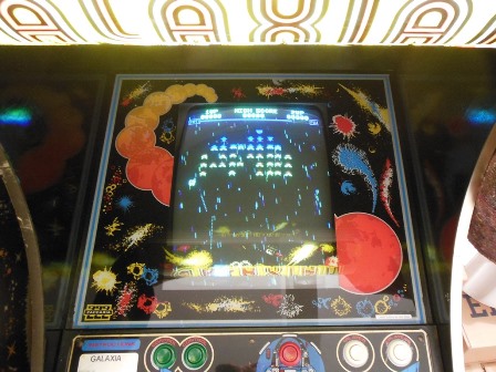
The MTC-900 chassis went in without any new issues and the initial picture quality was pretty good aside from a low red. After some adjustments the picture quality was good with the only noticeable artifact being some convergence misalignment.
|
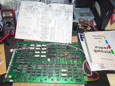
The game would not coin-up. Checking the wiring in the cab didn't find any issues so I suspected a board problem. Checking the board on the bench with a scope found that there were no row scan pulses being output from IC 5N (LS155). 5N pins 2 & 14, input ~EXTR, had poor logic low level. Since IC 5N happened to be in a socket already I removed it to verify that it wasn't a bad 5N input pulling up the ~EXTR signal and confirmed ~EXTR was still bad without 5N. Tracing ~EXTR upstream, IC 3O (LS02) pin 4 had poor logic low and pins 5 & 6 had good highs and solid lows so I suspected IC 3O was bad. Since IC 5M (40097) was also in a socket I verified that it wasn't pulling on ~EXTR either. Replacing IC 3O (LS02) fixed the coin-up problem and the game was working OK.


|
After several hours running the monitor would lose vertical sync. Given the very long time it took to get to this state I suspected that it was a thermal fault with the vertical IC when the cabinet internal temperature rose. To confirm that I used a heat gun around the chassis to isolate the thermal problem. Heating the TDA1470 vertical IC immediately caused the roll and removing the heat caused it to stop almost immediately.
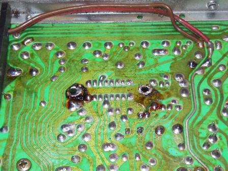
In order to remove the TDA1470, the large "U" heatsink must first be unscrewed followed by the desoldering of the heat sink mounting bracket over the top of the IC. I needed to use a large tip iron and maximum heat to be able to remove the heat sink bracket (hence the charred flux). With the heat sink bracket removed the IC could be de-soldered normally.

|
The process for fitting the new IC is not the same as the removal. First, the heat sink bracket is cleaned of old thermal compound and new thermal compound applied. Second, the new IC is placed but not soldered onto the PCB. Then, the heat sink bracket is fitted over the top of the new IC and soldered back in place. The IC pins must be soldered after the heat sink bracket because the IC needs to be pushed up from the PCB to properly contact the heat sink bracket rather than sit flush on the PCB (that would have left a gap between the IC and the heat sink bracket). The "U" heat sink can then be screwed back into place.
Reassembling and retesting with the heat gun showed no loss of vertical sync when hot and in cabinet the game ran fine for many hours.