|
|
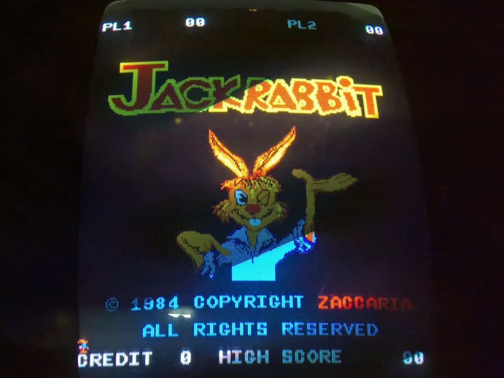
After initial setup on Thursday the game was running fine but by Friday morning it had developed a sprite graphics problem. Swapping in a spare board fixed the game but after another couple of hours there was no picture. Further investigation found no signs of life on the monitor and I suspected that the monitor chassis had died. I had no spare monitor chassis so the game was withdrawn to the dead zone :(

|
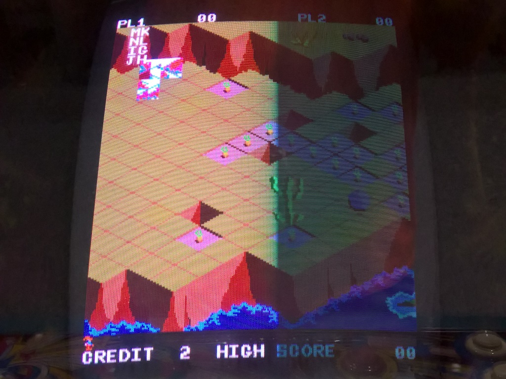
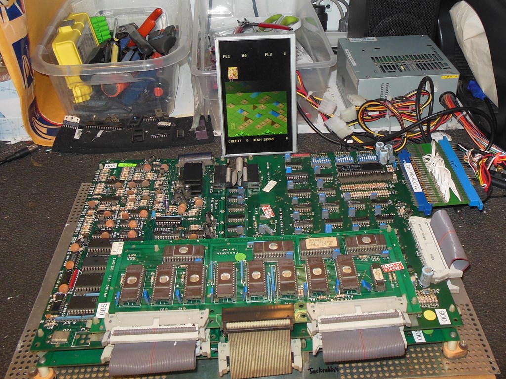
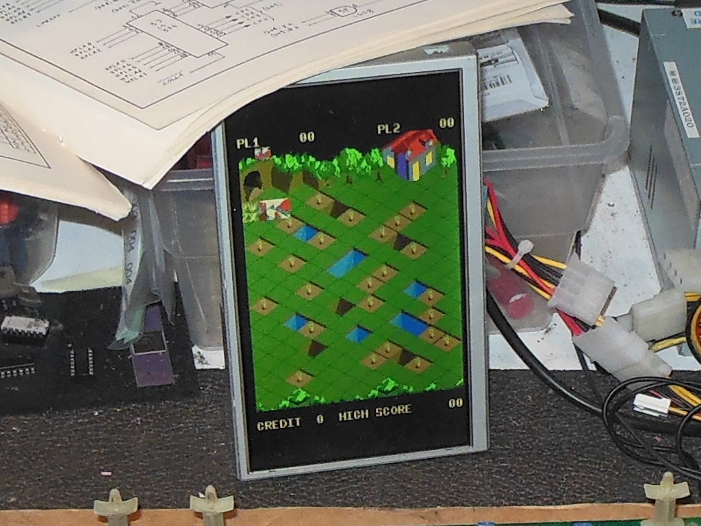
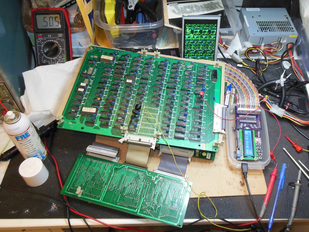
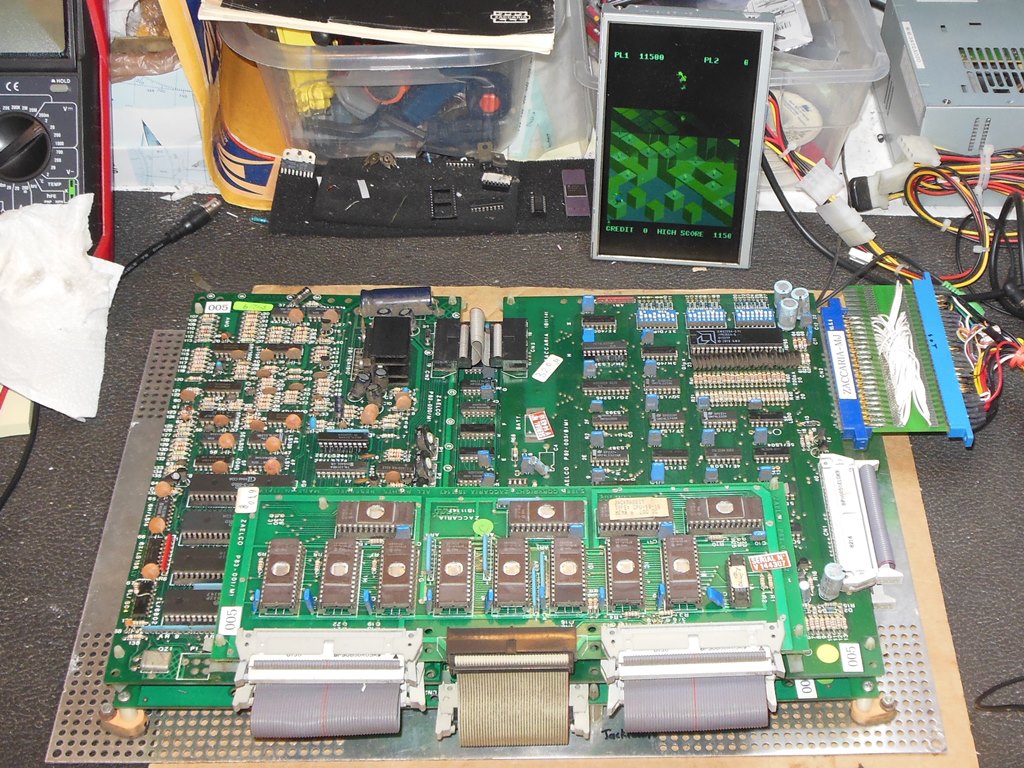
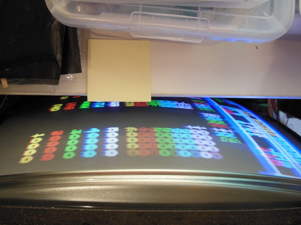
On the bench the sprite problem was still present. As the attract mode played through it also became clear that the background scrolling on sheet 2 wasn't correct. A quick check of the video RAM by swapping them around didn't have any effect on the symptom thus I suspected that the video RAM was OK.
Checking IC 2J (LS374) with a scope found pins 17 & 18 (HPLA6 & HPLA7) sometimes had poor logic levels. Shorting together pins 11 & 12 on IC 1M (2114) had little effect on screen. Using the Arduino ICT confirmed that the video RAM was OK. With "RAM Write All Lo" the address bus of IC 1M looked OK (video clocks present). With "RAM Write All AD", a write of data = address, IC 1J (LS241) pin 2 input looked OK but pin 18 output was bad. Similarly pin 4 input was OK but pin 16 output was bad. I suspected IC 1J (LS241) was bad but I none at hand and thus replacements were ordered.
|
|
Replacing IC 1J (LS241) did not fix the problem, IC 1J pin 18 (HPLA7) and pin 16 (HPLA6) still had poor logic levels. The scope confirmed the input pin 2 was good. The HPLA signals form a video bus the goes to various places and with the output IC already replaced this hinted that one of the inputs it feeds was overloading or clamping the output signal. From the schematics the HPLA6 & HPLA7 lines feed:
The next idea was to measure the voltage drop from the output to the inputs to narrow where the drop was occurring:
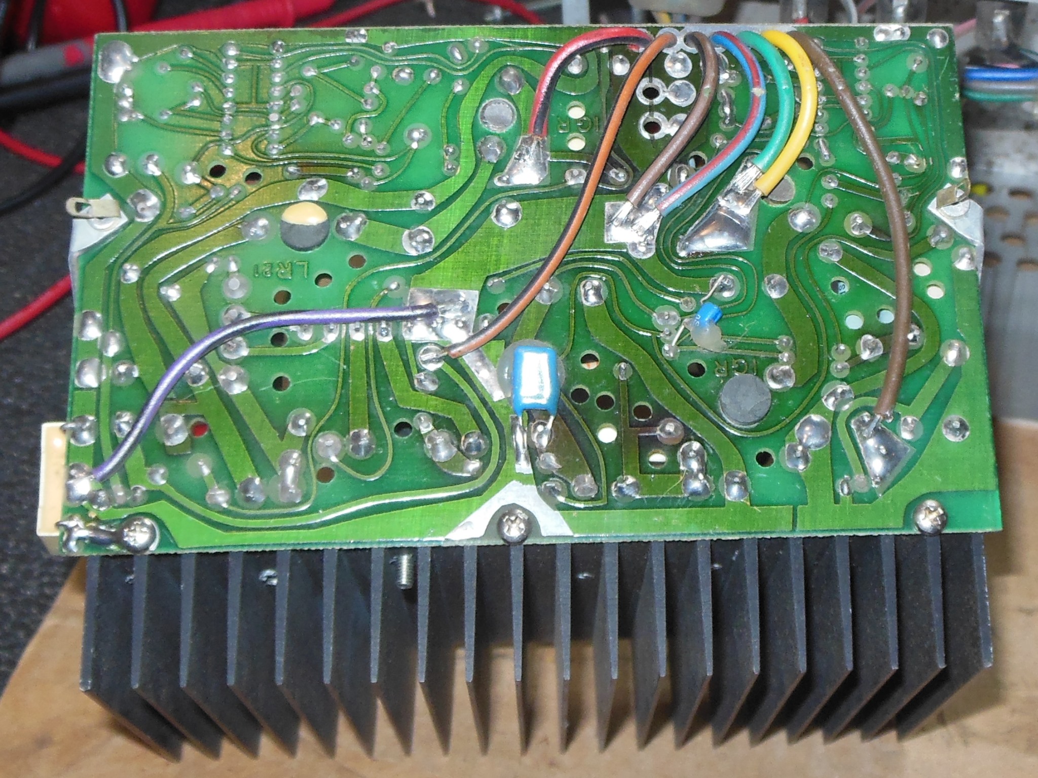
After two dead ends, the third idea was to combine the voltage drop measurement with freezer spray, based on the theory that the overloading/clamping IC may exhibit a voltage change with temperature. I setup the meter on IC 1J reading a baseline of 0.520V and then passed over each of the destination IC's in turn with a drop of freezer spray. There was a small variation at IC 4J (LS374) where the voltage dropped to 0.513V. All other destination IC's had no change with freezer spray. Using a soldering iron to reheat IC 4J brought the voltage back to 0.520V. The experiment was repeated to confirm - freezing dropped ~7mV and heating raised it back up again. No other destination IC exhibited this behavior so I suspected IC 4J was the problem. Replacing IC 4J (LS374) fixed the sprites and HPLA6 & HPLA7 looked healthy on the scope :)
|
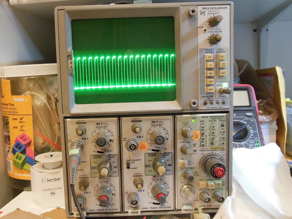
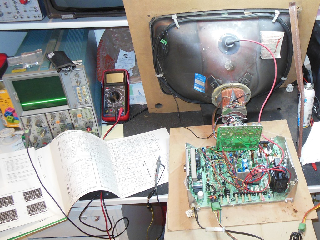
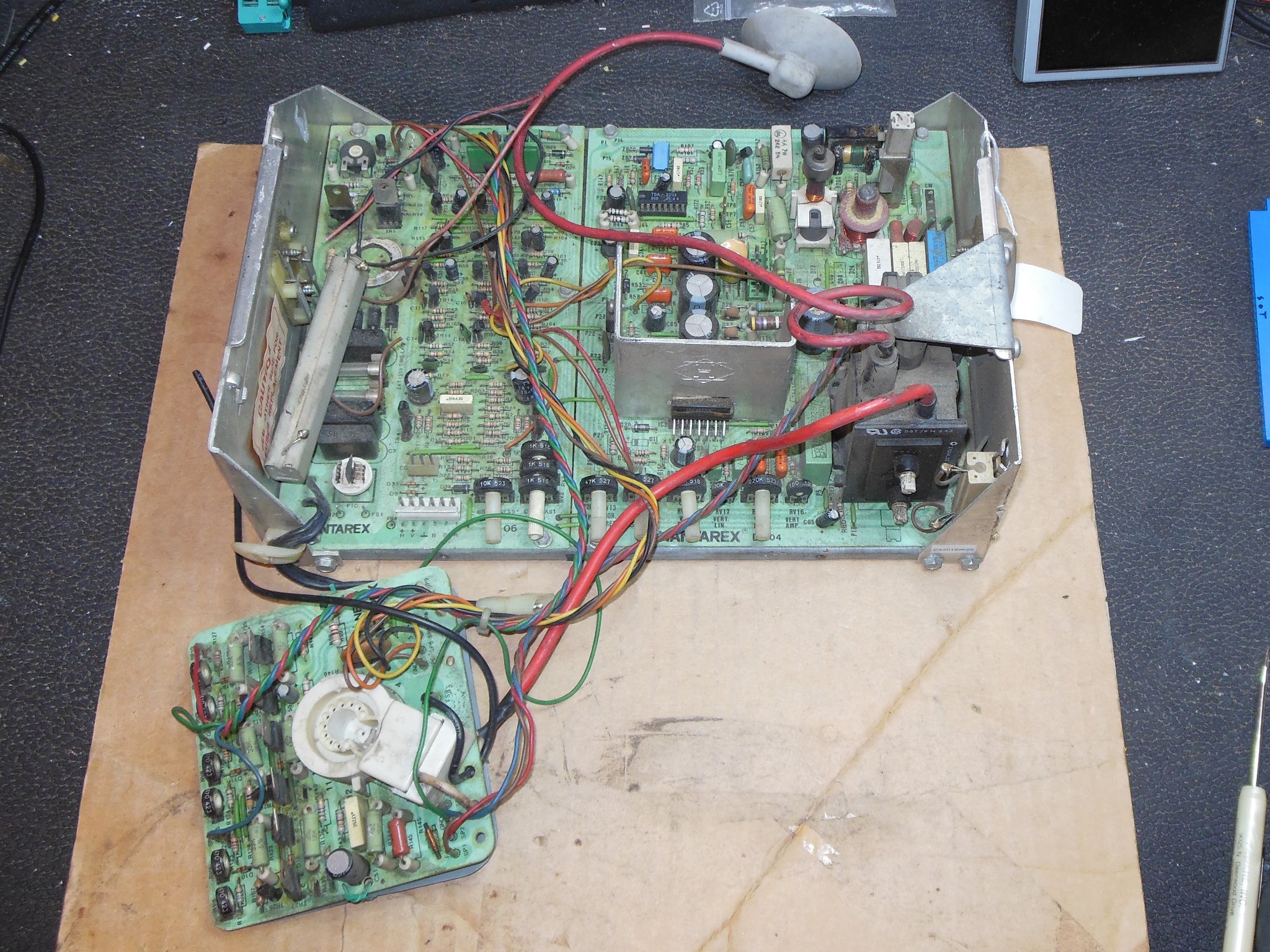
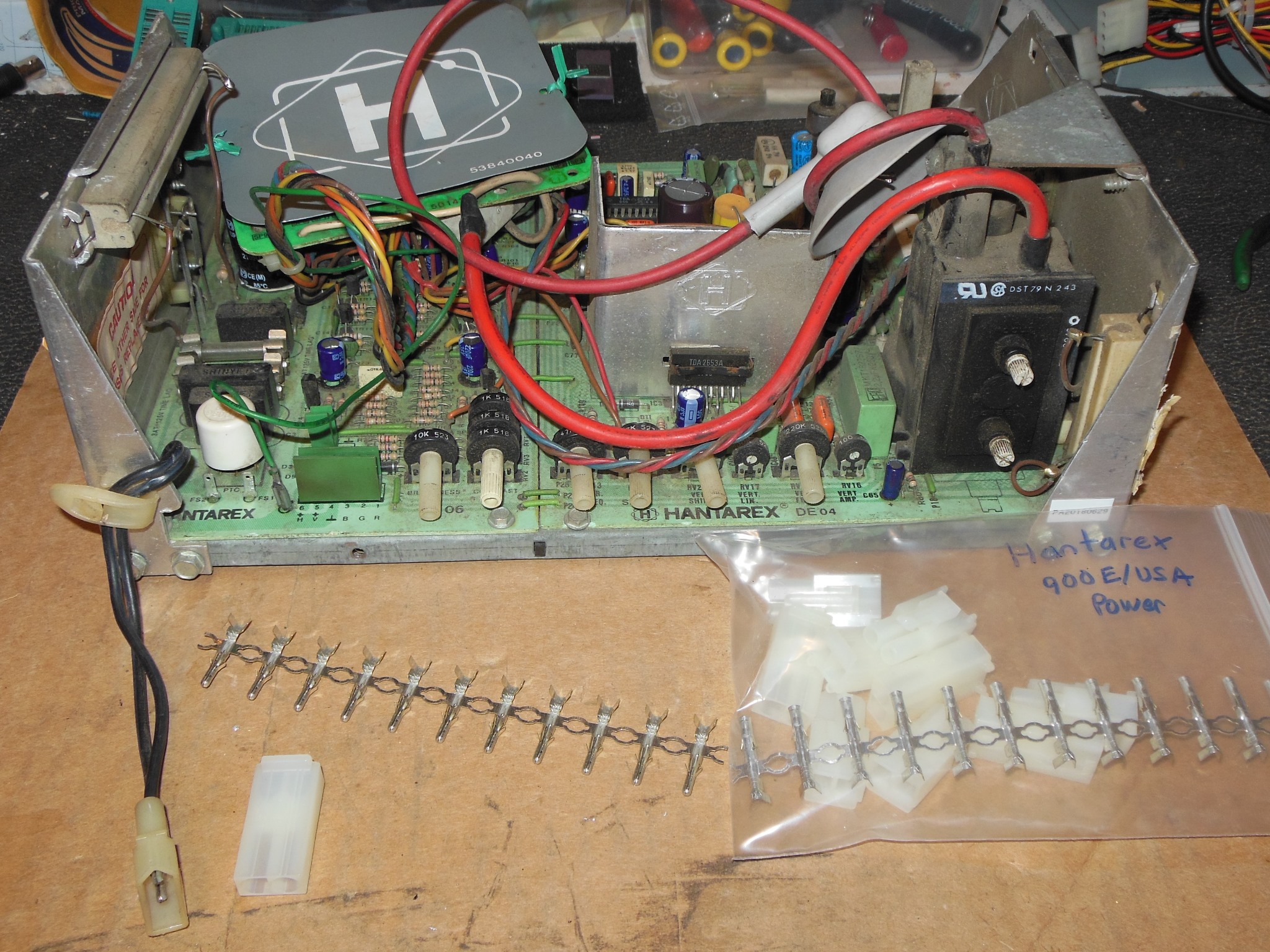
At the show my initial triage notes were that the chassis had no neck glow or other signs of life, the chassis input voltage was good and the game coined up OK, suggesting the chassis was bad. On the bench the Hantarex MTC-900E/USA chassis powered up OK but without vertical sync lock.
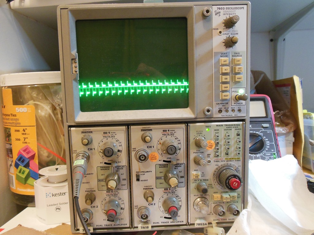
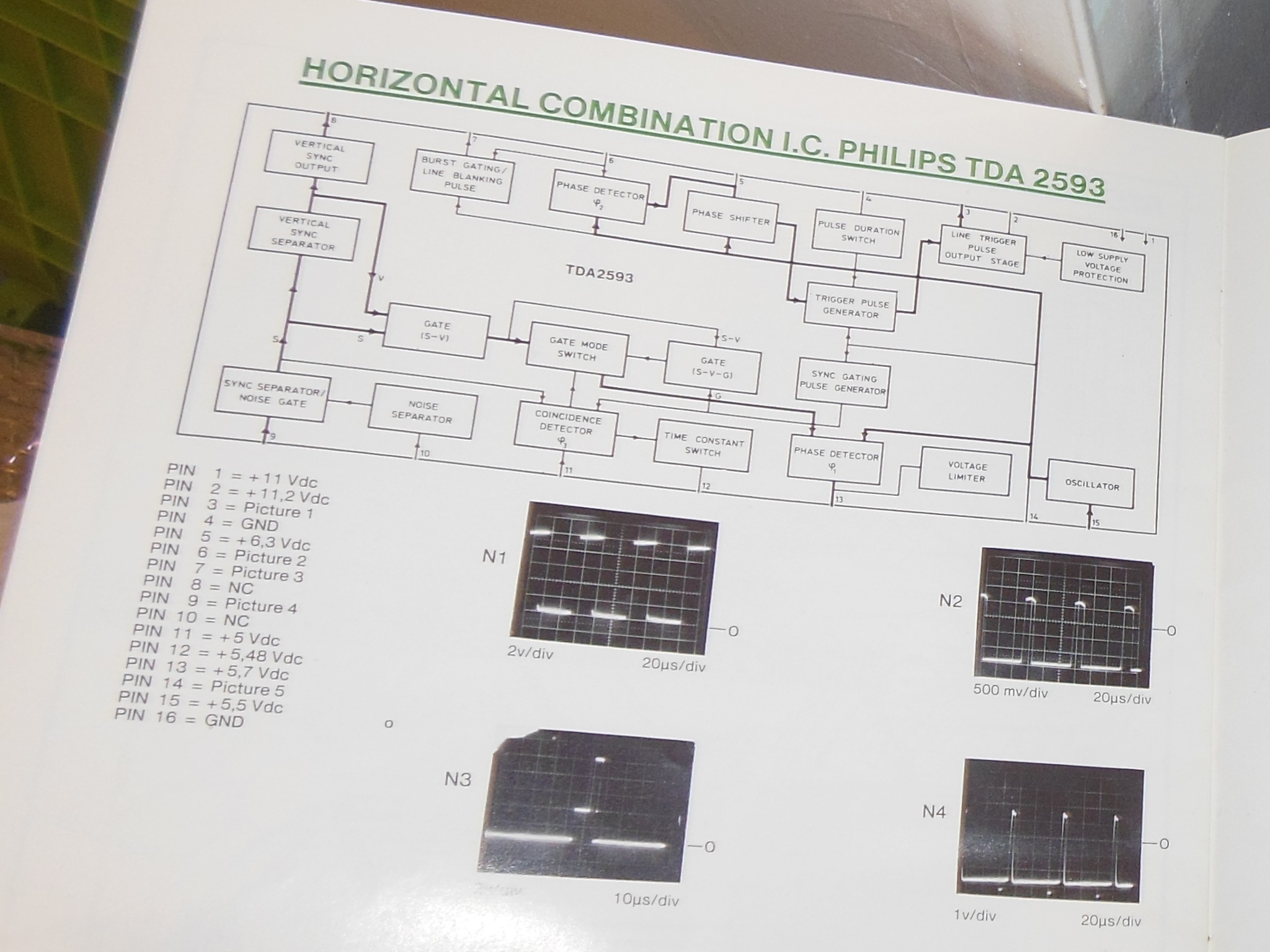
The Hantarex schematic for the chassis showed that the vertical sync output from IC2 (TDA2593) pin 8 fed into IC3 (TDA2653A) pin 2 however on the scope I saw vertical sync at IC2 but not IC3. I suspected a bad passive component or open track between the two. Closer inspection of the chassis revealed that C201 and other components were not populated on this chassis. Also, the Hantarex manual page describing the TDA2593 showed pin 8 as NC (not connected). With this connection missing, the only path for vertical sync input was from the vertical sync input connector pin that was not connected on my test bench harness. Bridging the horizontal & vertical input connector pins together fixed the vertical sync and thus there was no issue with the chassis.

|
Since this was the same test harness I had used for the other 900E/USA in Money Money that was working OK and I had that chassis to hand I confirmed that it had the internal vertical sync connection populated and thus this was why this chassis worked OK with only the horizontal sync input connected.

|
After reinstalling the chassis the monitor powered on with neck glow and HV but a blank screen. Checking the IGR power supply found no +5V and thus I must have made a mistake in diagnosis at the show. I removed the power supply for bench testing.

|
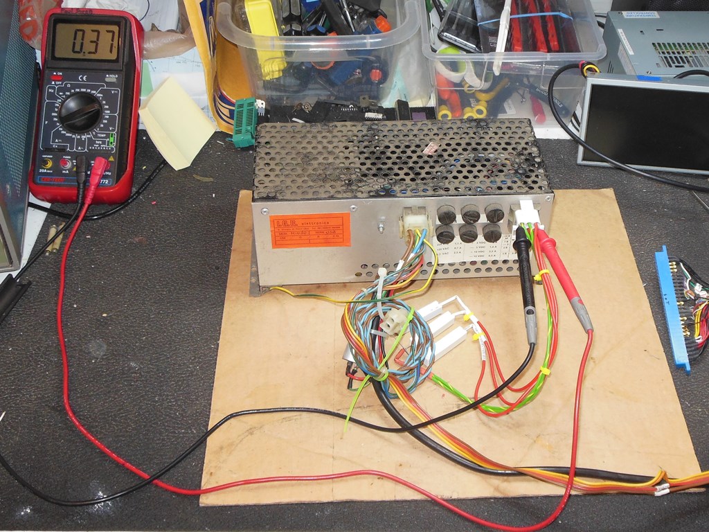
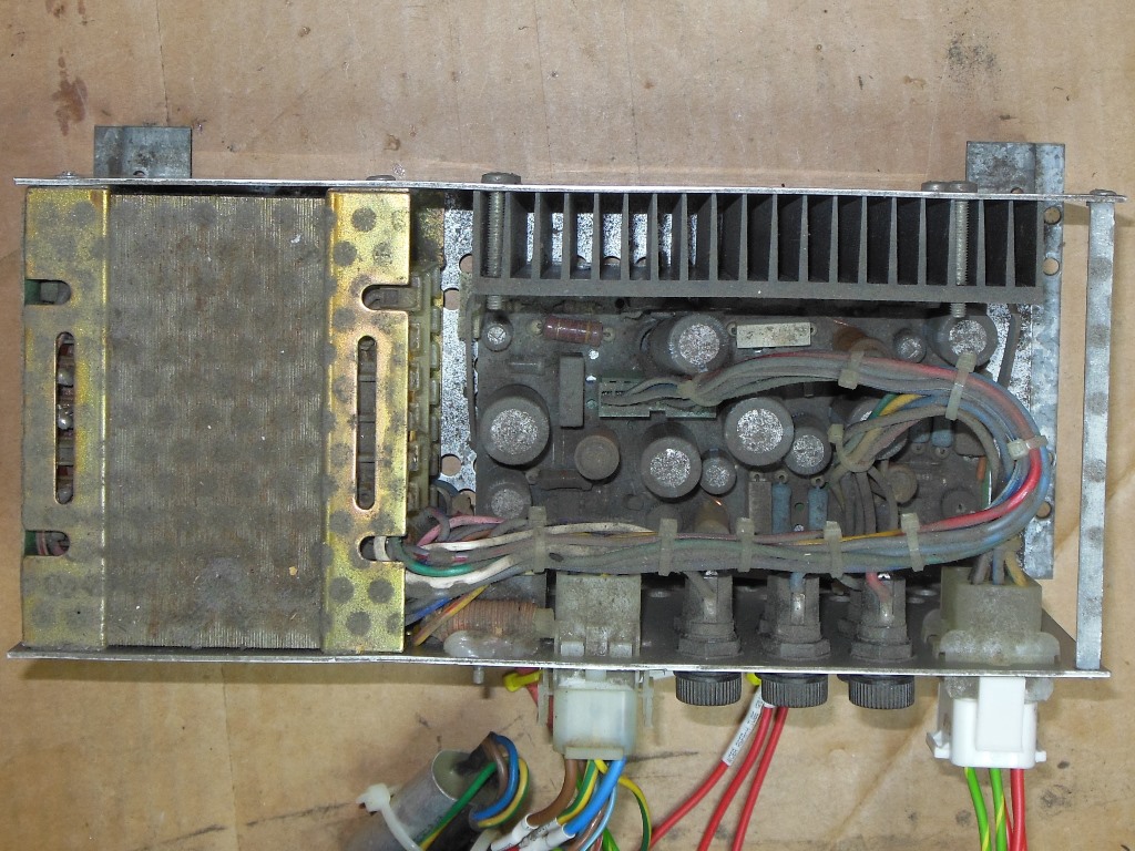
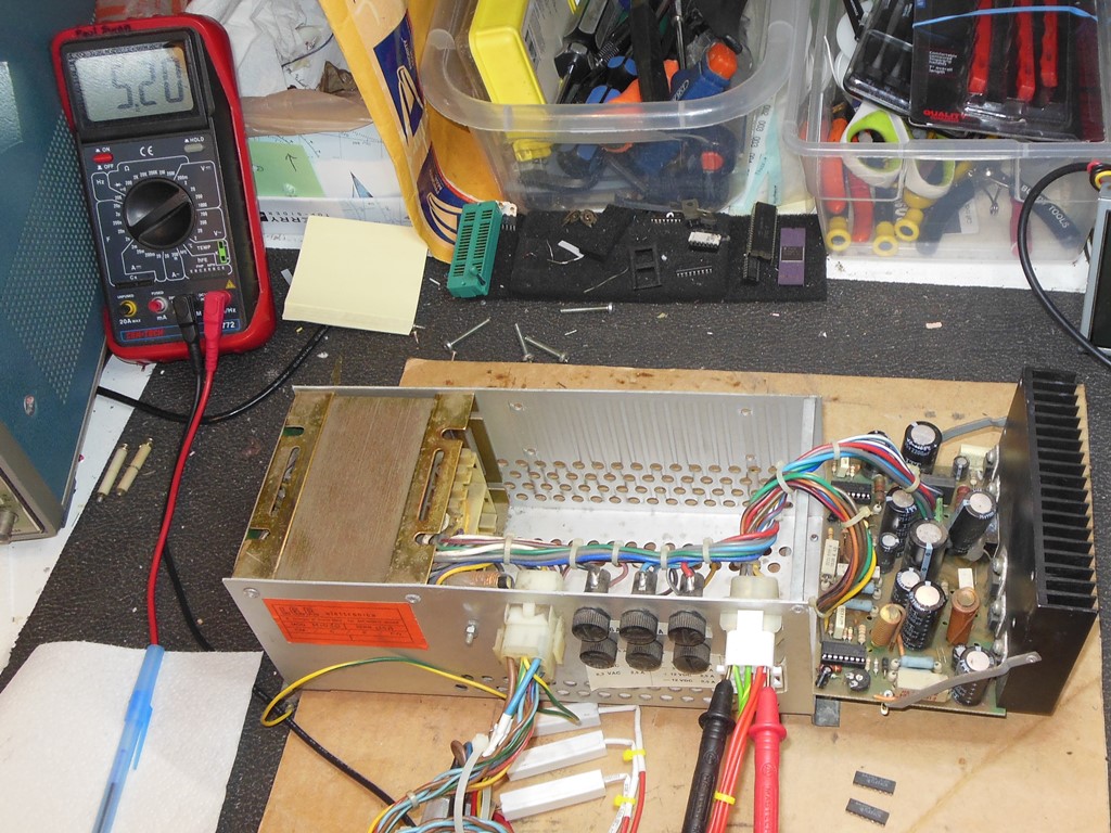
On the bench the +5V measured +0.37V confirming the power supply wasn't working. The unit was very dirty inside & out so the first step was to clean out all the dust for a visual inspection.
|
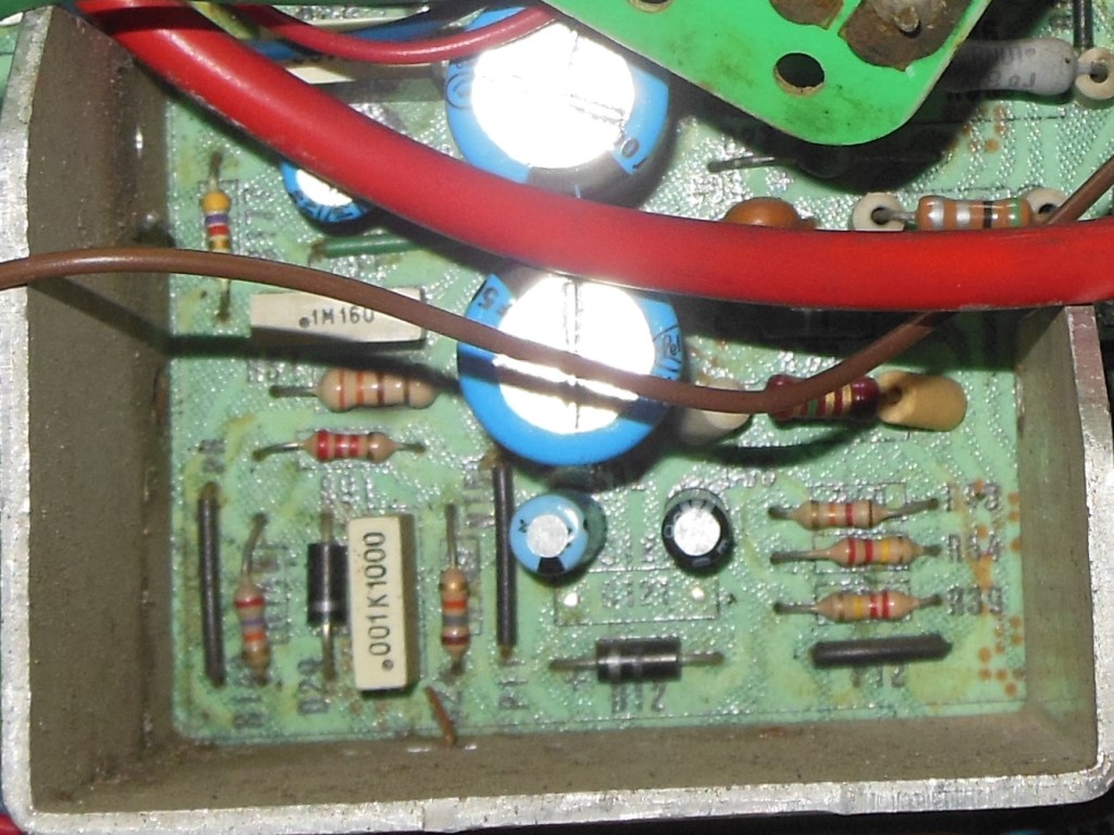
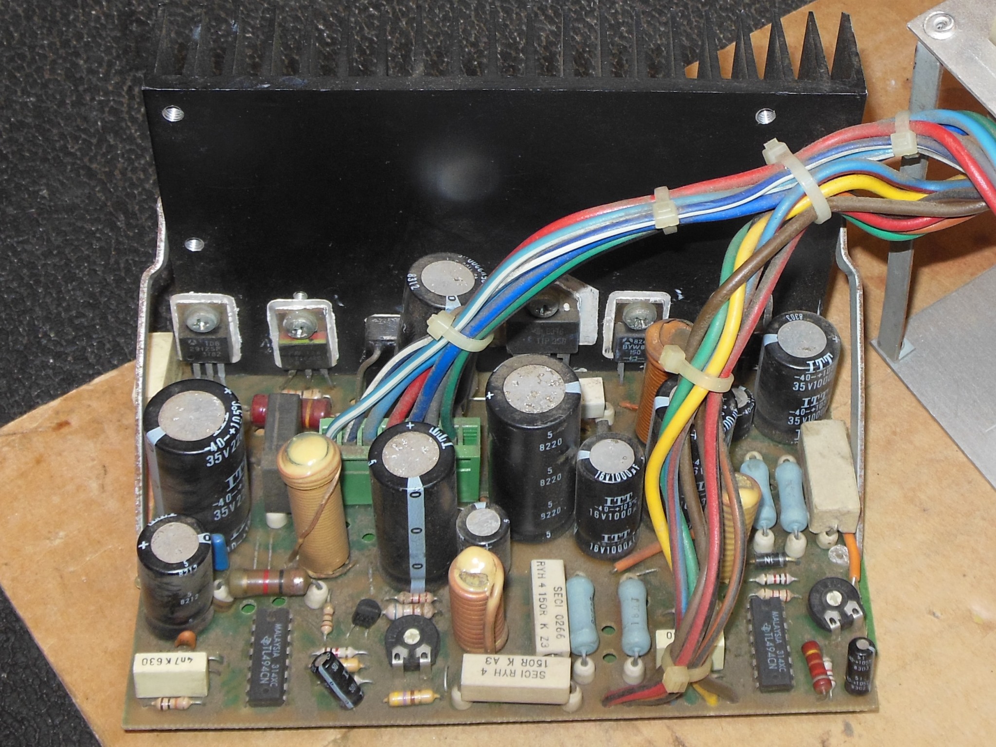
Under all the dust the power supply PCB was in good condition with very little corrosion. So far all the fixes to this power supply had been replacement of the TL494 switching regulator ICs so I went with that as step one, replacing both +5V and +12V TL494 (though the +12V was currently working on this supply, a pre-emptive measure). After the TL494 were replaced the +5V was back working OK and adjusted to +5.20V as a starting point. The power supply ran on the bench for a few hours with no further issues.
|
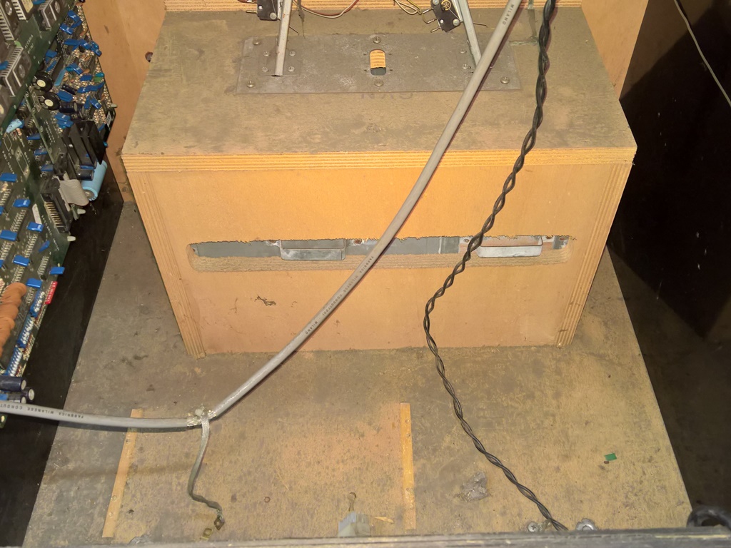
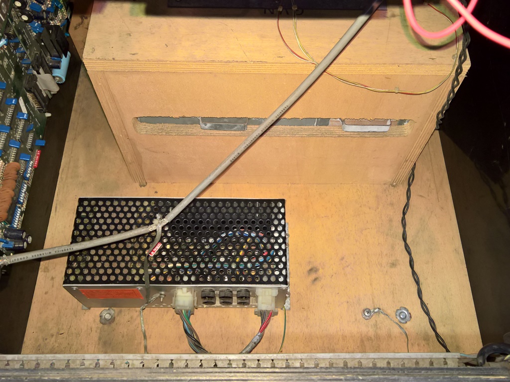
Since the cabinet floor was filthy just like the power supply I took the opportunity to clean it out whilst the power supply was out. With the IGR power supply refitted the game came up working OK with a healthy +5.01V measured on the game PCB. The game ran for a few hours with no further issues.
|
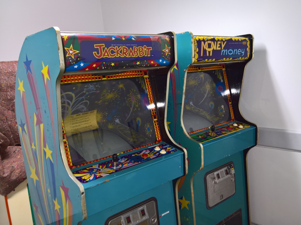
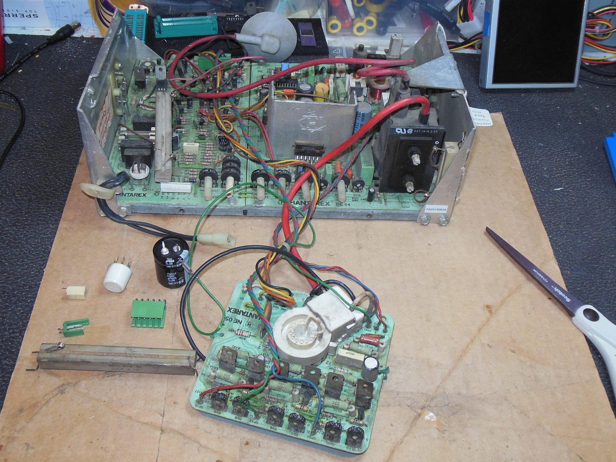
I had only two games that used Hantarex MTC-900E/USA chassis, Jackrabbit & Money Money. Over the years in the show one or both of them developed issues so I decided to restore a third chassis to use as a spare. It's a relatively rare chassis to find in the US. This spare I bought off eBay was a little beat up and needed some repair work to it before trying to power it on.
A visual inspection identified the DC regulation capacitor missing, the degauss PTC broken, the regulation power resistor broken, a cap pulled off and the connectors for video input were mismatched from the other chassis I had. All of these were repaired.
|
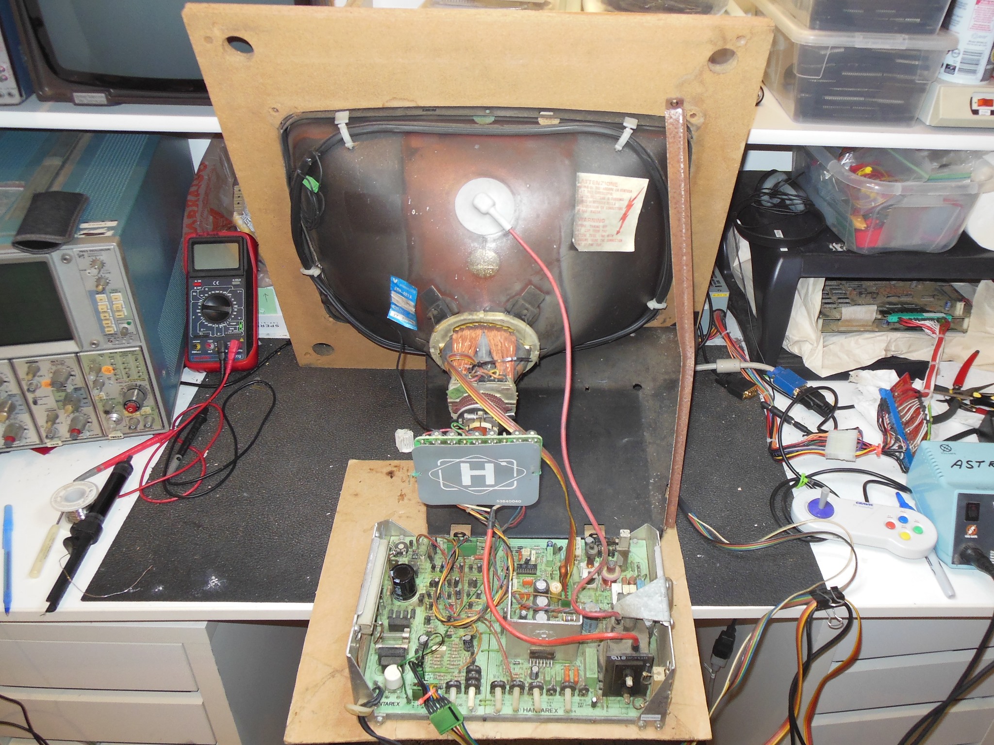
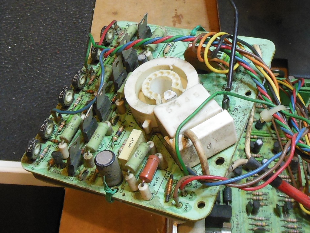
On power on the picture was stable and bright but with colours bleeding. After a few minutes smoke trailed up from the neck PCB. Resistor R140 (560 Ohm) had burned up. Neck transistor TR31 (BF871) failed a back-to-back diode check. Diode D31 tested OK in circuit. Transistor TR30 (BF871) also failed a back-to-back diode check in circuit that was confirmed out of circuit. Both TR30 & TR31 were replaced and the chassis retested.

|
After a few minutes of testing, smoke again trailed up from the neck PCB. Resistor R139 (560 Ohm) had burned up. TR27 (BF871) tested bad in circuit. Suspicious there was something wrong on the chassis that was causing the neck transistors fail I removed TR27 and verified that the +200V supply measured +206V and the +12V supply measured +12.28V, both seemingly reasonable. I could find no cause for the unusual double failure.
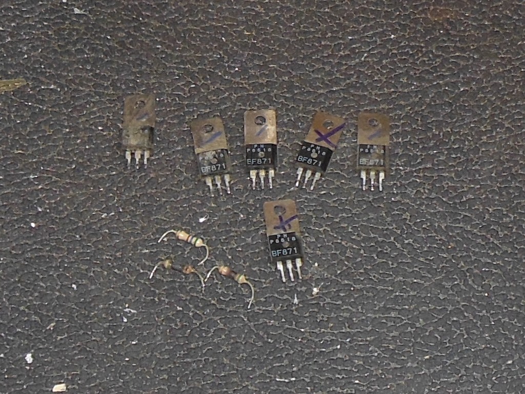
After a few more minutes, smoke again trailed up from the neck PCB a third time. The last of the three resistors, R142 (560 Ohm) burned up. I removed all 4 of the remaining BF871 transistors from the neck PCB and they all tested bad out of circuit. Over the course of a couple of days all of the neck PCB BF871 had failed and burned up all three 560R resistors. After replacing all of that the chassis was running fine again and I adjusted the picture to something reasonable.
After 10 minutes the screen turned blue. Checking with a scope, TR26 (BC237) was different than the red & green instances with C-E looking flatline on the scope. Replacing TR26 had no effect however - there was still no signal on TR26 collector. TR27 (a previously replaced BF871) was removed and tested bad on the Hfe meter. Replacing TR27 fixed blue and there were no further issues after several hours on the bench.
|
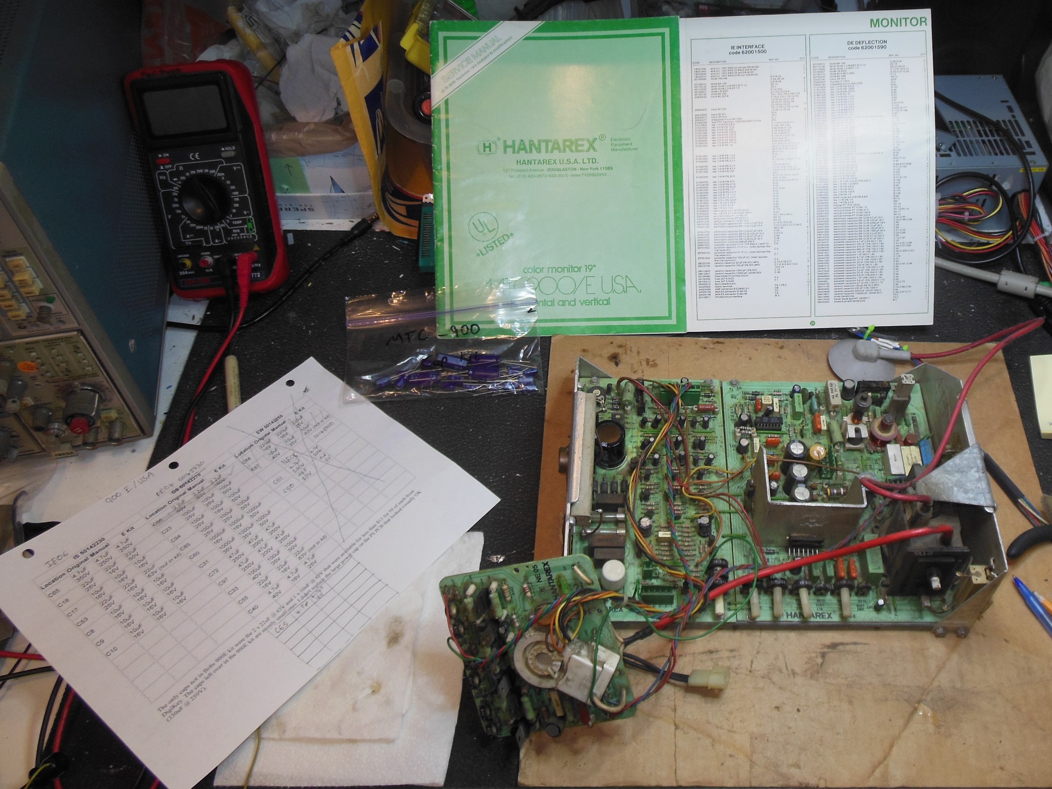
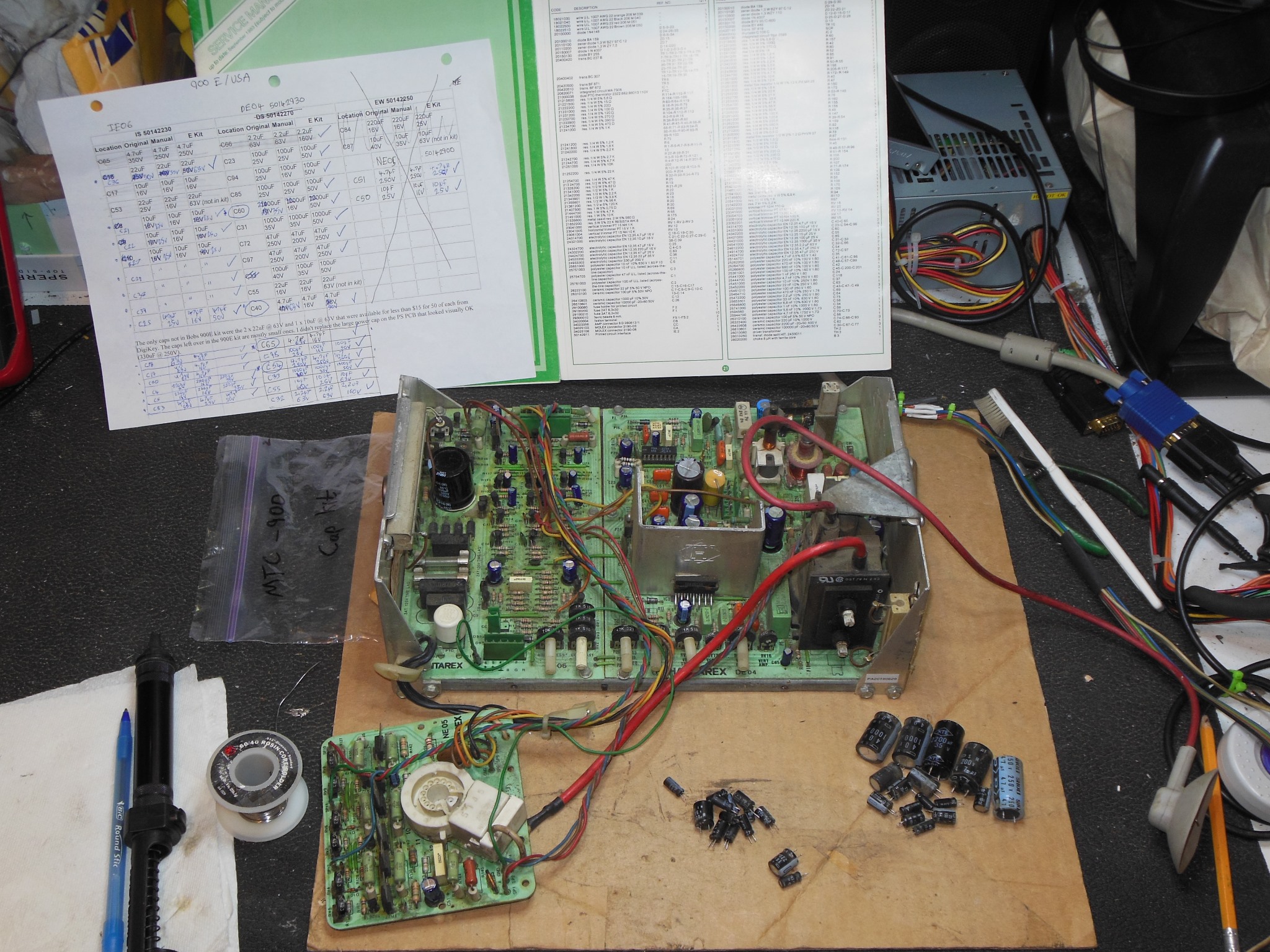
Having finally run out of Bob Roberts Hantarex 900E cap kits I needed to make up my own kit for this chassis. It shares a lot of similarities with the earlier 900 and is almost the same cap-wise as the European 900E:
| IE06 | DE04 50142930 | NE05 50142250 | |||||||||
|---|---|---|---|---|---|---|---|---|---|---|---|
| Location | Original | Manual | Kit | Location | Original | Manual | Kit | Location | Original | Manual | Kit |
| C36 | 22uF 50V |
22uF 35V |
22uF 63V |
C32 | 2.2uF 63V |
2.2uF 63V |
2.2uF 160V |
C51 | 4.7uF 250V |
4.7uF 250V |
4.7uF 250V |
| C21 | 10uF 25V |
10uF 16V |
10uF 25V |
C23 | 100uF 25V |
100uF 25V |
100uF 50V |
C50 | 10uF 25V |
10uF 16V |
10uF 25V |
| C22 | 10uF 25V |
10uF 16V |
10uF 25V |
C94 | 100uF 25V |
100uF 16V |
100uF 50V |
. | . | . | . |
| C38 | 10uF 25V |
10uF 16V |
10uF 25V |
C85 | 100uF 25V |
100uF 25V |
100uF 50V |
. | . | . | . |
| C27 | 10uF 25V |
10uF 16V |
10uF 25V |
C60 | 2200uF 35V |
2200uF 16V |
2200uF 50V |
. | . | . | . |
| C29 | 10uF 25V |
10uF 16V |
10uF 25V |
C31 | 1000uF 35V |
1000uF 35V |
1000uF 50V |
. | . | . | . |
| C39 | 10uF 25V |
10uF 16V |
10uF 25V |
C72 | 47uF 250V |
47uF 200V |
47uF 250V |
. | . | . | . |
| C18 | 4.7uF 63V |
4.7uF 16V |
4.7uF 50V |
C97 | 47uF 250V |
47uF 200V |
47uF 250V |
. | . | . | . |
| C19 | 4.7uF 63V |
4.7uF 16V |
4.7uF 50V |
C40 | 4.7uF 63V |
4.7uF 16V |
4.7uF 50V |
. | . | . | . |
| C20 | 4.7uF 63V |
4.7uF 16V |
4.7uF 50V |
C65 | 4.7uF 63V |
4.7uF 16V |
4.7uF 50V |
. | . | . | . |
| C4 | 220uF 16V |
220uF 16V |
220uF 35V |
C98 | 100uF 25V |
100uF 16V |
100uF 50V |
. | . | . | . |
| C5 | 220uF 16V |
220uF 16V |
220uF 35V |
C54 | 4.7uF 250V |
4.7uF 250V |
4.7uF 250V |
. | . | . | . |
| C83 | 47uF 50V |
47uF 25V |
47uF 50V |
C33 | 1000uF 40V |
1000uF 35V |
1000uF 50V |
. | . | . | . |
| C25 | 47uF 25V |
47uF 16V |
47uF 50V |
C55 | 10uF 40V |
10uF 25V |
10uF 63V |
. | . | . | . |
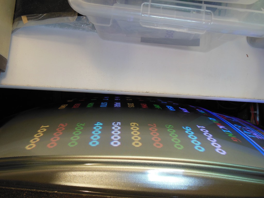
There were no problems with the cap kit and the picture quality was good. The chassis ran on the bench for a day with no further issues.
|
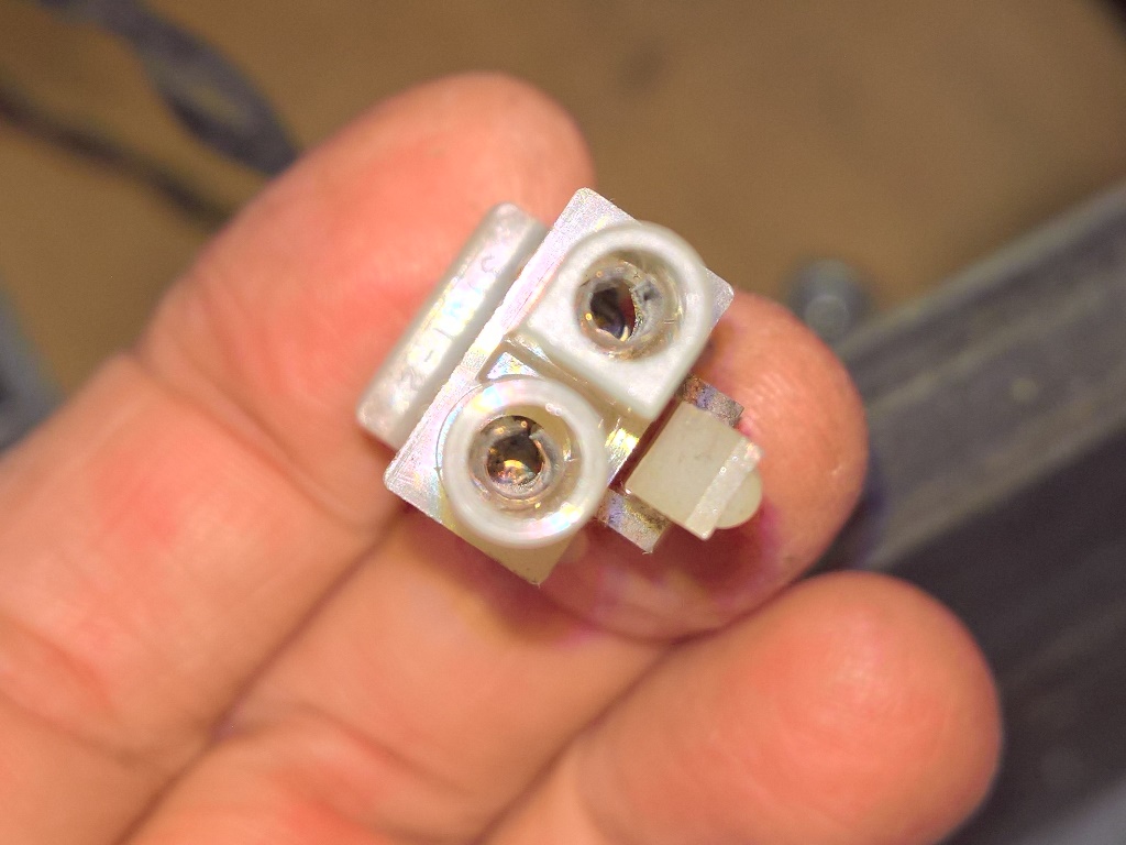
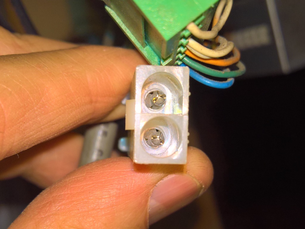
Given the chassis didn't have the usual Hantarex connectors on it I suspected it came out of a none-Zaccaria game. The power socket was the US WG style one that didn't fit the plug in the Zaccaria games. A little bit of investigation found that the correct plug for the Zaccaria games was a 2-pin 0.093" Molex free hanging available from eBay for $10 for a complete set of five plugs and five sockets. The connector & pins were verified correct on Jackrabbit and fitted to the chassis, completing the spare chassis.