|
|
|
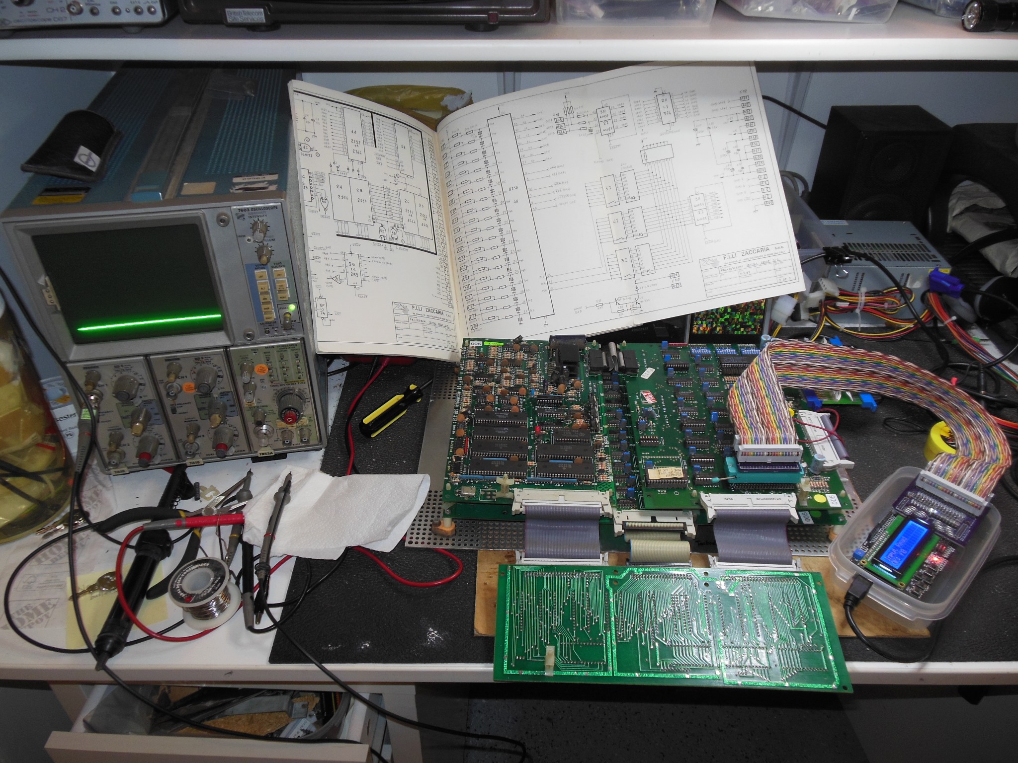
After initial setup on Thursday the game was running fine but by Thursday night the game PCB was no longer booting. Replacing the game PCB with spare one on Friday morning found that the spare PCB was booting but stuck in test mode showing all the DIP switches off. I'd seen this before when the 8255 fails so I swapped the 8255 from the none-booter into the spare but alas this time it didn't fix the issue. The game was withdrawn into the backroom and I took the two game PCB's home to fix on Saturday aiming to fix one and get the game back on the floor on Sunday.
I started investigating the none-booting PCB #003 with the Arduino ICT and found that all ICT tests passed and the inputs/DIP switches all read OK. With a replacement Z80A CPU the game booted and ran without issue and the old Z80A was confirmed bad.
Next I looked at game PCB #005 that booted stuck in test mode. I'd already tried
swapping over the 8255 without success so the 8255 was presumed working OK.
Checking the 8255 pins on the scope found:
Early Sunday morning the repaired game PCB #003 was installed back into the cabinet and the game returned to the show floor where it ran fine through to closing.
|
Basic triage during the show hadn't turned up any obvious problem with
accessing the DIP switches inspecting with the scope. On the bench with the Arduino
ICT reading the dip switches returned 0xFF, consistent with the game. IC 3H/2I (40067)
pin 1 (~RDSW) pulsed low on read. IC 4H (8255) had previously been swapped with
the other PCB and thus seemed to be OK. On the scope, pulses were seen on
IC 4H pin 11, but the signal was not staying active. IC 4H ~CS, AB0 & AB1 all
appeared to have good active pulses. The control panel inputs read OK through 4H.
Using two channels on the scope found that during the read active on IC 3H pin 1
IC 4H pin 11 (PC6) was not active. This appeared to be the issues - the 8255
control pin PC6 was not staying active to allow the DIP switch to be read. Checking
The 8255 ~CS and ~WR signals look fine on the scope and AB0 & AB1 were also high
during the cycle as expected. Inspecting the RESET signal also found no issue - there
was reset at power on that was properly cleared. Checking the data bus during the set
PC6 & set mode operations using individual Arduino ICT output write operation found
the following:
| Pin | Write PC6 | Mode |
|---|---|---|
| 34 | 1/0 | 1/0 |
| 33 | 0 | 1 |
| 32 | 1 | 0 |
| 31 | 1 | 0 |
| 30 | 0 | 1 |
| 29 | 0 | 0 |
| 28 | 0 | 0 |
| 27 | 0 | 1 |
Manually pulling down PC6 confirmed that the DIP switch could be read. Using the repeat function on the Arduino ICT found that PC6 briefly toggled low during the write of the pin mode. A mode output write of 0x93 resulted in PC6 high. A write of 0x92 resulted in PC6 low but a write to bit control PC6 of 0x0d or 0x0c did not reenable PC6 low. The PCB was set aside pending a comparison with a known working PCB :(

|
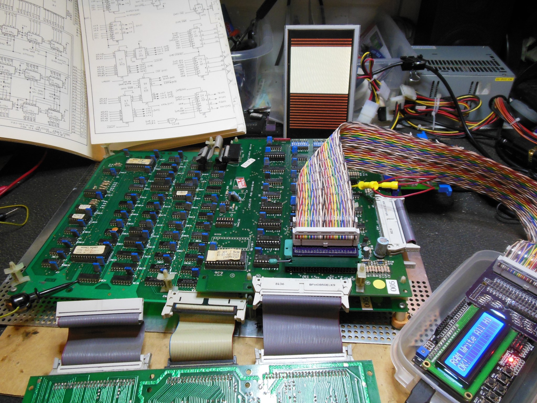
A known good Money Money PCB #002 confirmed that PC6,PC5,PC4 all toggled as expected in response to the programming of mode and control PC. On the scope, the ~CS signal was active for ~1000ns and the ~WR signal ~500ns. The address pins AB0 & AB1 were both high. Notably writing the pin mode did not impact PC6 and PC6 only changed when the PC bit control word was written. ~CS to ~WR setup was ~400ns and ~CS hold after ~WR was a few ns. Both address & data were all stable long in advance of the cycle.
|
Moving back to the Jackrabbit PCB #005 confirmed the ~CS & ~WR timing matched #002. I measured around 200ns after the mode write that PC6 changed to active. Checking the data bus a second time during the mode write of 0x92/0x93 found it to be correct.
|
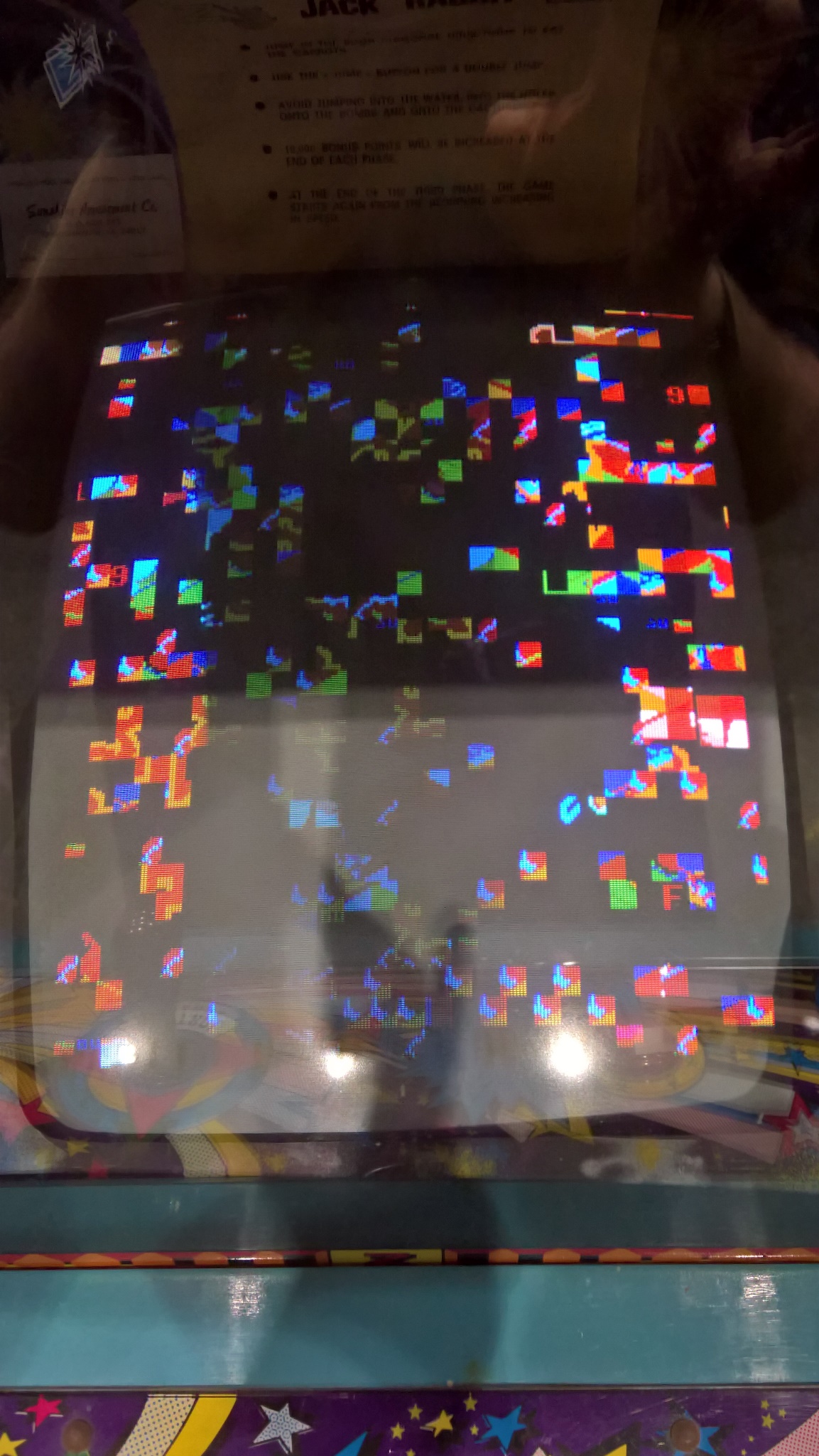
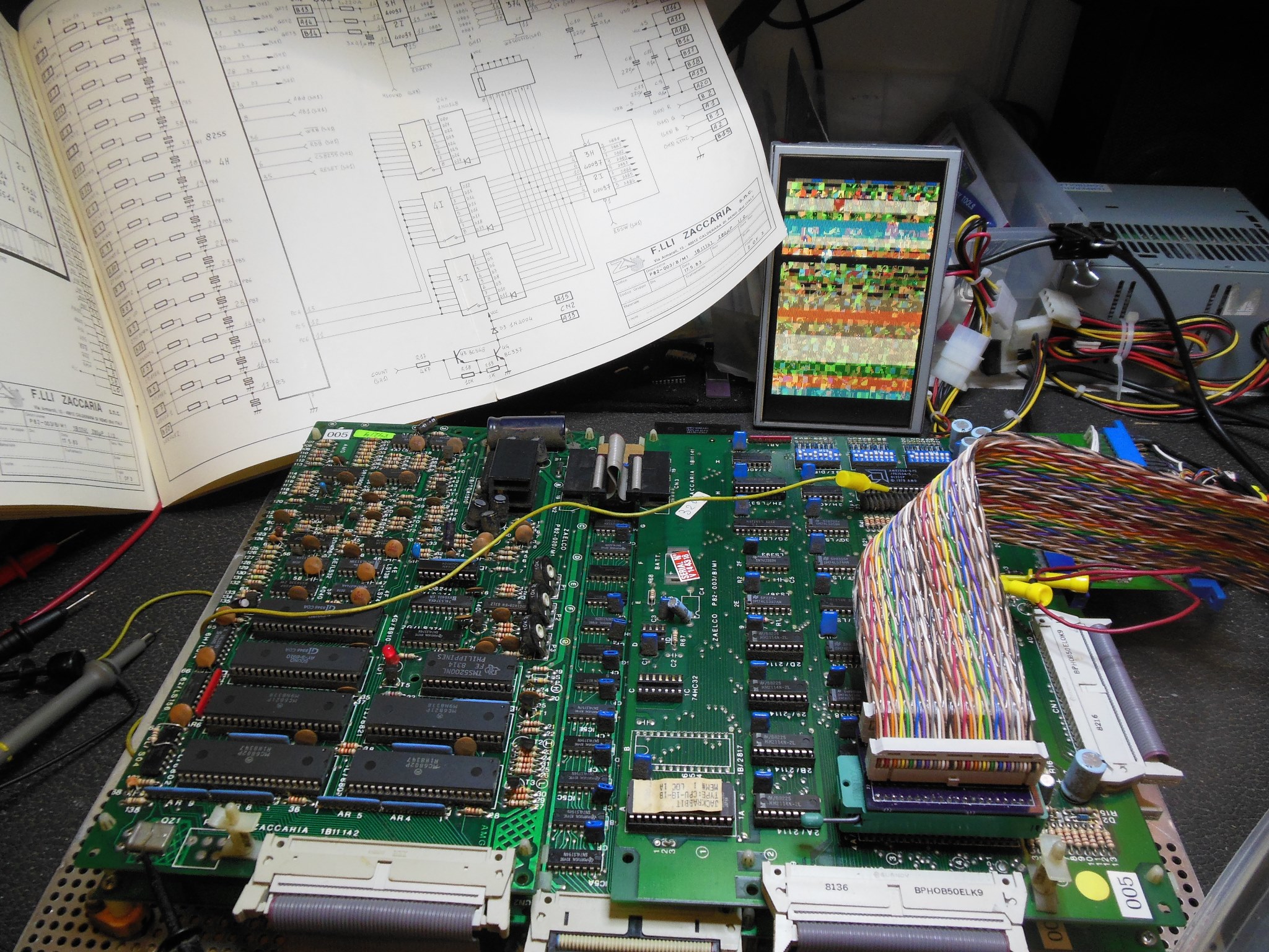
At this stage I had no further ideas on what might be causing the 8255 writes to not work correctly and the PCB had developed another fault with lines appearing in the graphics. I decided to abandon this set in defeat and instead convert a 3rd spare Money Money PCB into a 2nd spare Jackrabbit :(
|
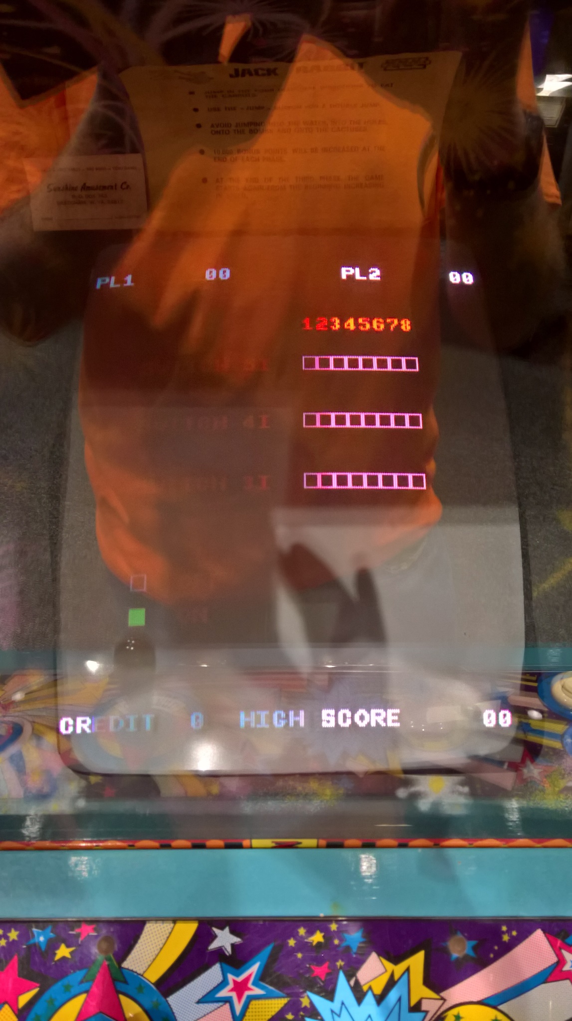
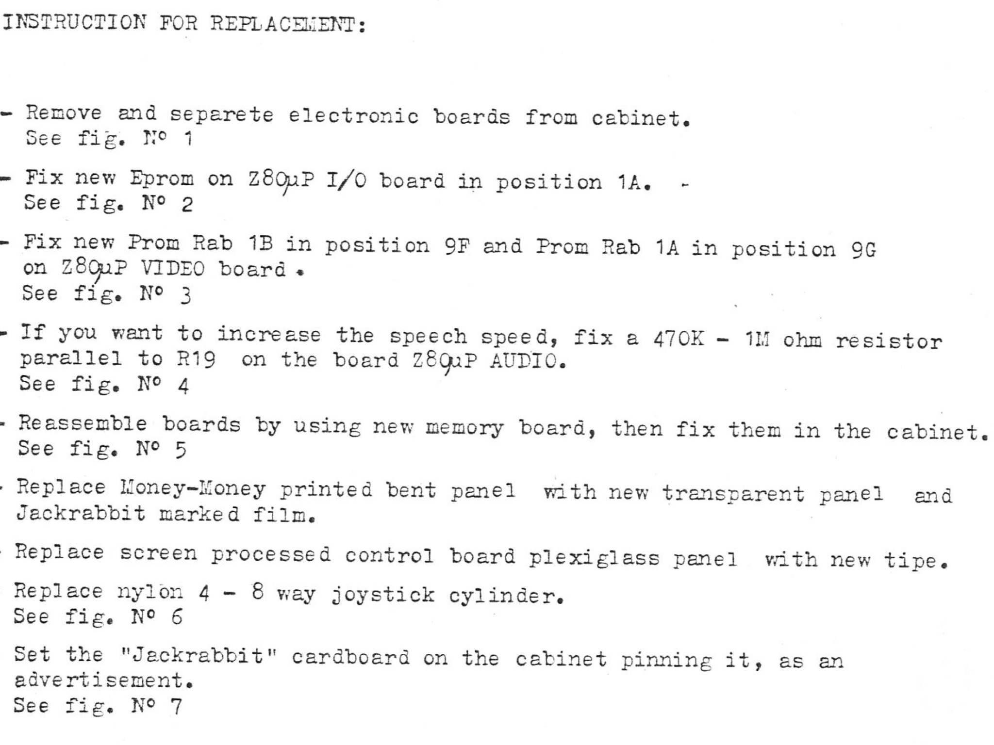
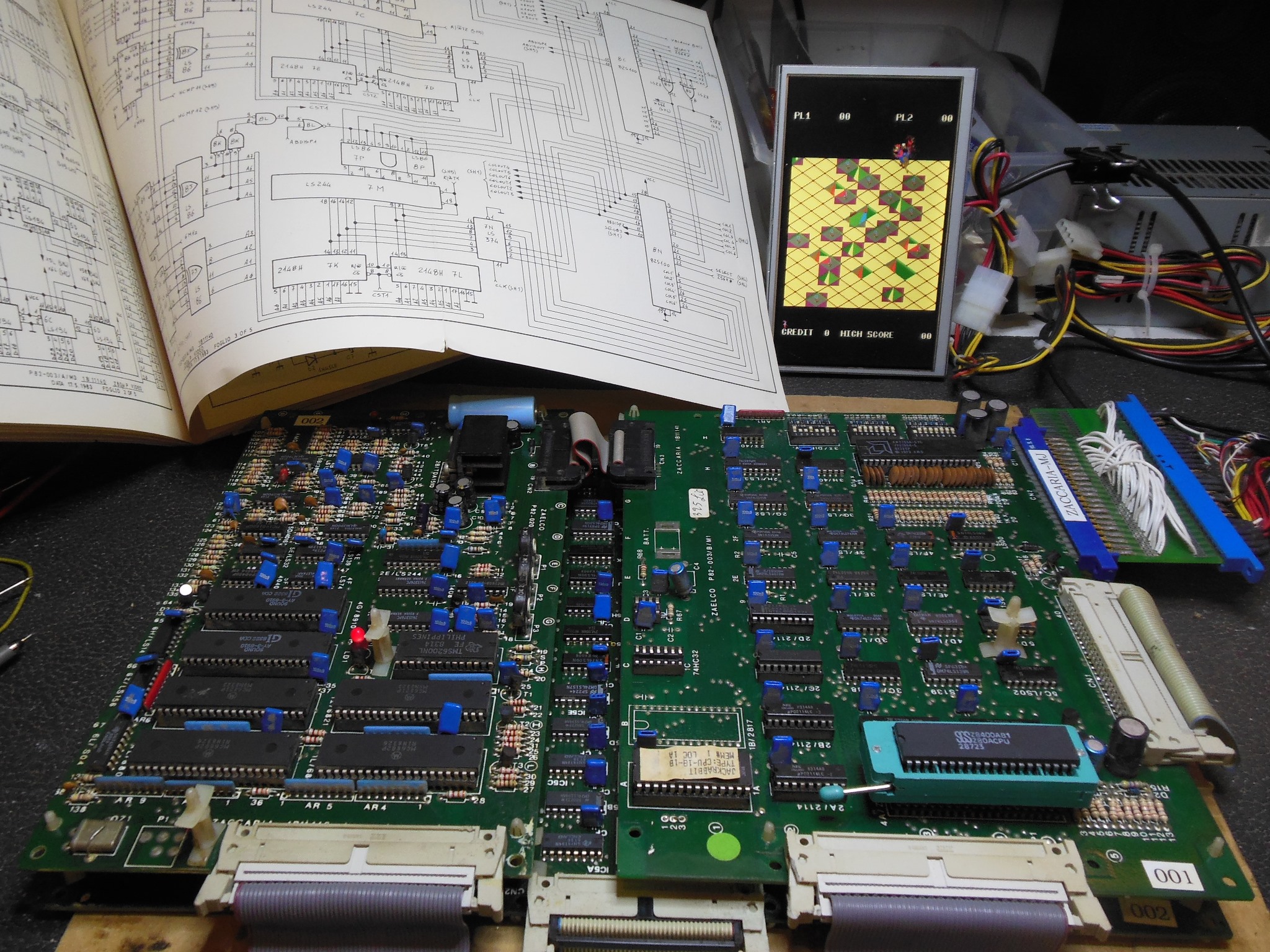
Jackrabbit was originally available as a conversion kit for Money Money and thus a conversion instruction manual exists that conveniently outlines the parts to change. Basically, swap the ROM board, CPU board ROM and video board PROMS. The game booted fine after the conversion (the photo above is before the video PROMS were swapped and thus the display isn't yet correct).


|
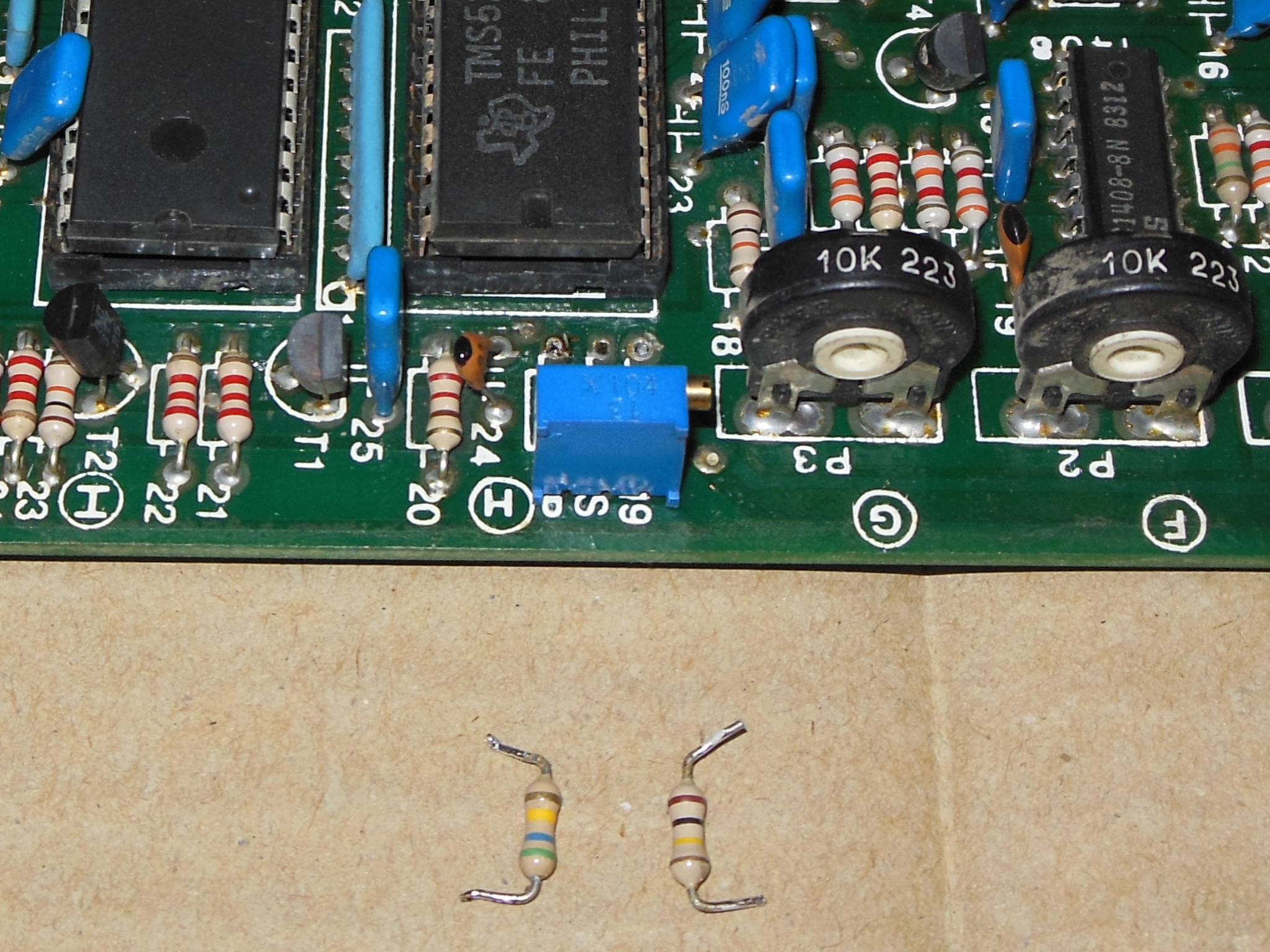
As noted in the conversion steps, the speech speed isn't aligned with the video using the Money Money settings. I'd previously encountered the speech speed not aligning on other Jackrabbit PCBs that were prior Money Money conversions. To allow the speed to be adjusted easily I'd replaced the fixed tuning resistors with a 100K trimmer pot and then manually trimmed the speed to match video.

|
The TMS5200 manual describes the trimming procedure. In the Zaccaria case the capacitor for the RC circuit was 22pF versus the 10pF in the datasheet that thus was better served with a 100K pot (increased capacitance equates to decreased resistance for the RC circuit). I didn't directly calibrate against the frequency itself but instead used the scope to help gauge the trimming was slowing or speeding and then compared against the game for video sync.