|
|
The game started out running OK then began to exhibit partial vertical collapse that eventually became full vertical collapse to a horizontal line by the second day. I swapped in an unknown spare WG XY daughter board for the WG4600 monitor that restored the picture but by the end of the show the picture was showing vertical compression at the top.

|
On retest the monitor had very bad sync. The spare XY board I'd fitted at the show was all original so the first step was to remove it and fit a cap kit.


|
The rest of the monitor had already had a cap kit fitted so only the spare XY board needed to be brought up to date.

|
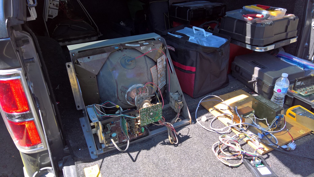
The cap kit of the spare XY board had no effect on the sync problem. There was an upcoming Seattle Metro Arcade Collectors (SMAC) repair party with local experts in attendance who'd be able to advise on this type of monitor so I decided to pull out the monitor and fetch it along to the repair party for testing.
|
At the repair party on the truck bed test bench the monitor was out of adjustment but working OK with no issues. This unfortunately suggested a cabinet or board problem with the game :(

|
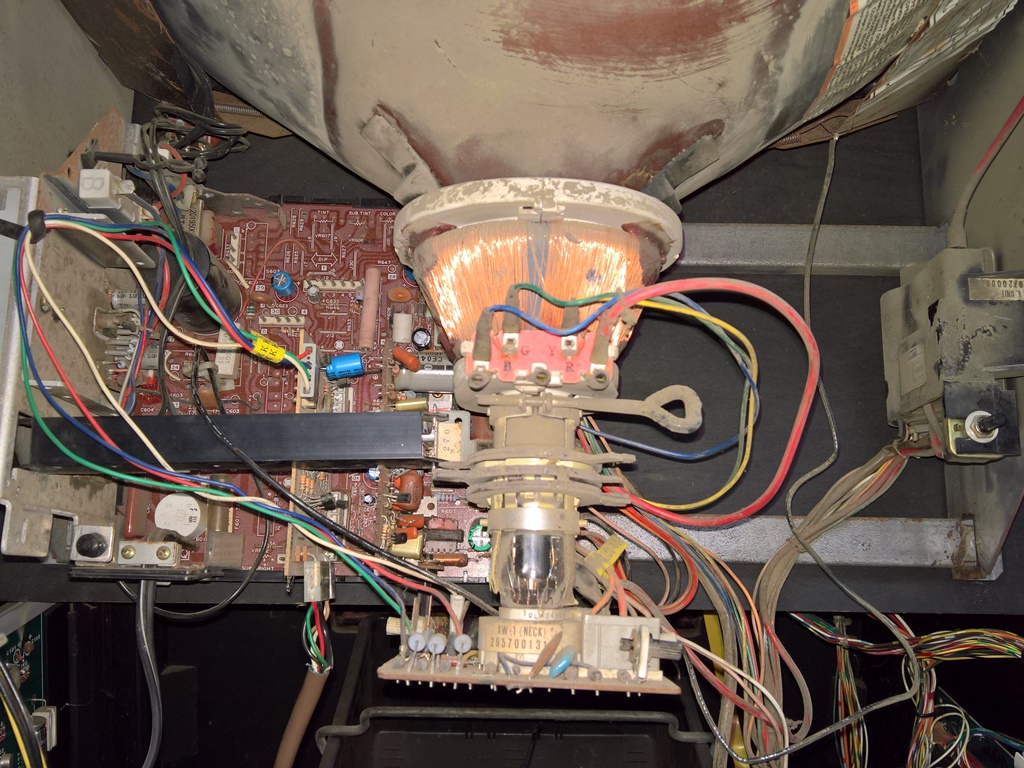
Connected back up to the cabinet the monitor came up fine as it had at the repair party (so the original sync problem was for now an unsolved mystery). Whilst the sync was good the brightness was low and unstable (fading dark and then bright). Adjusting the black level pot hit a white out before a bright picture. I decided to look again at the original modifications to the P305 input board that were needed to match the WG4600 monitor inputs more closely to the WG4900 monitor that was originally in the cabinet, and also prepare a second spare input board.
|
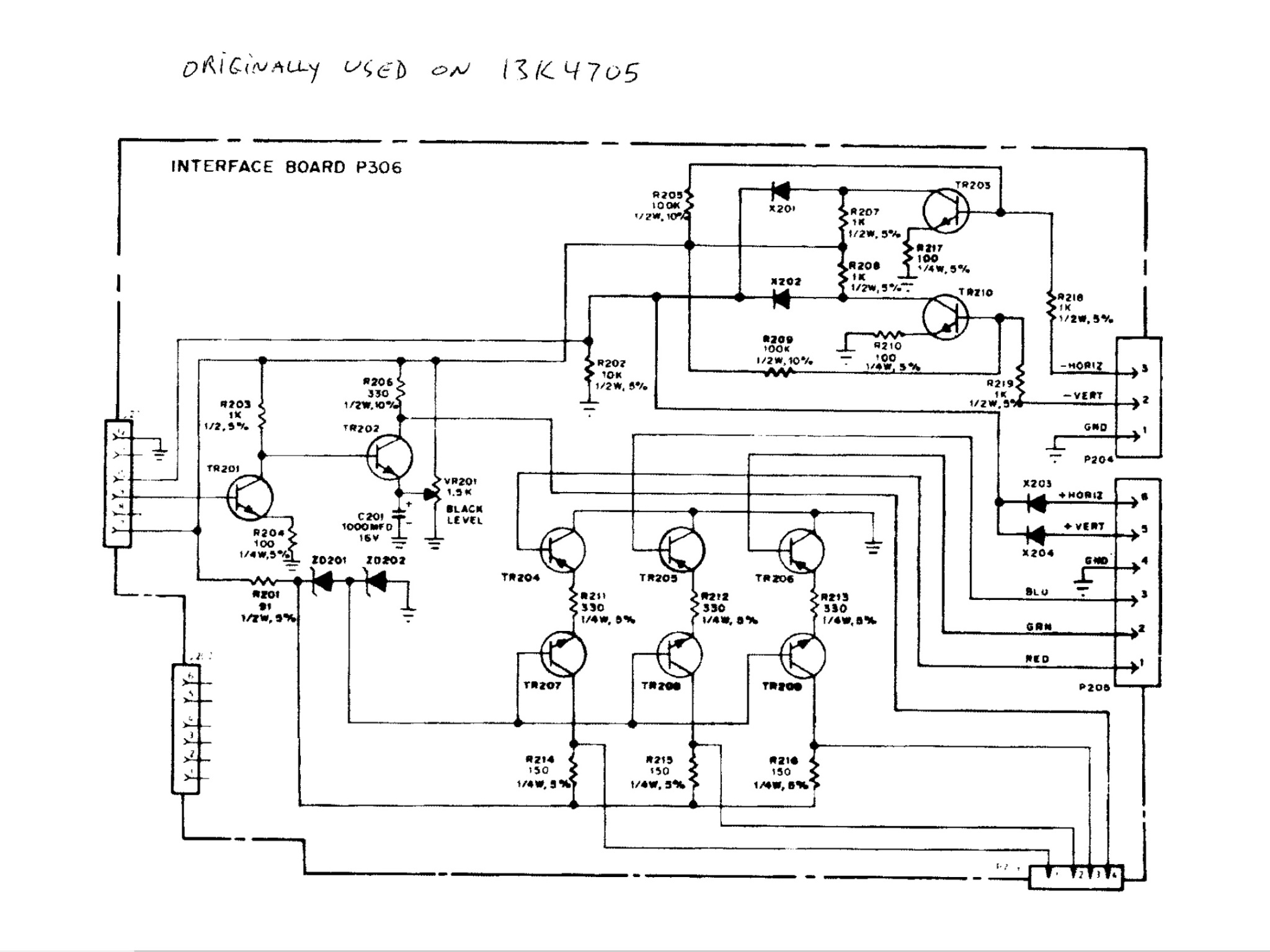
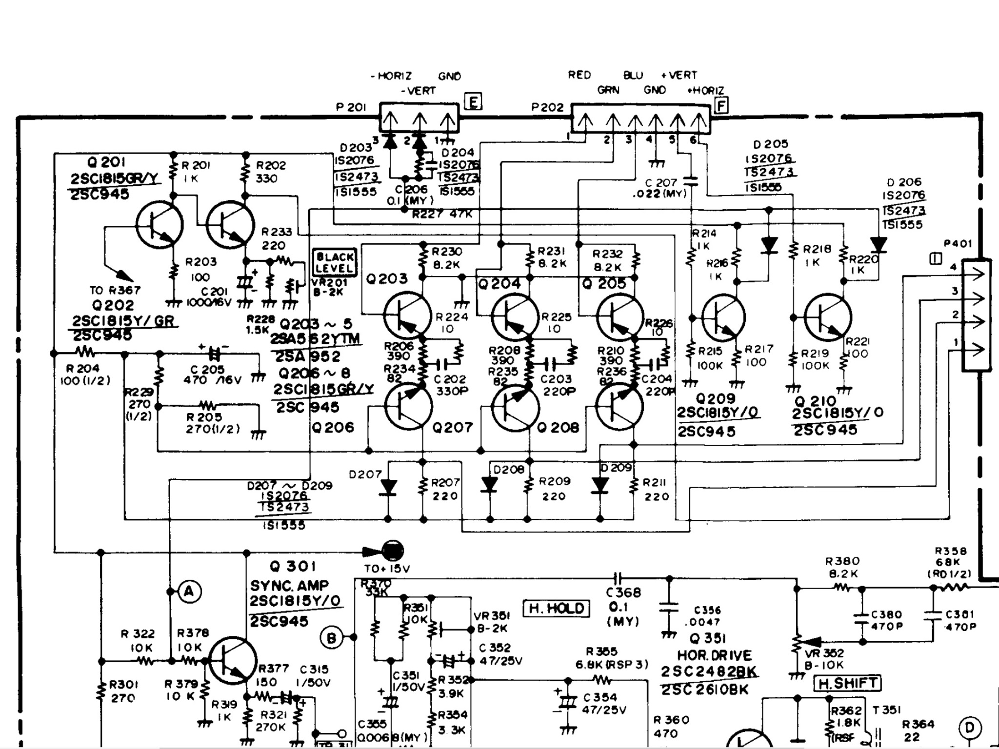
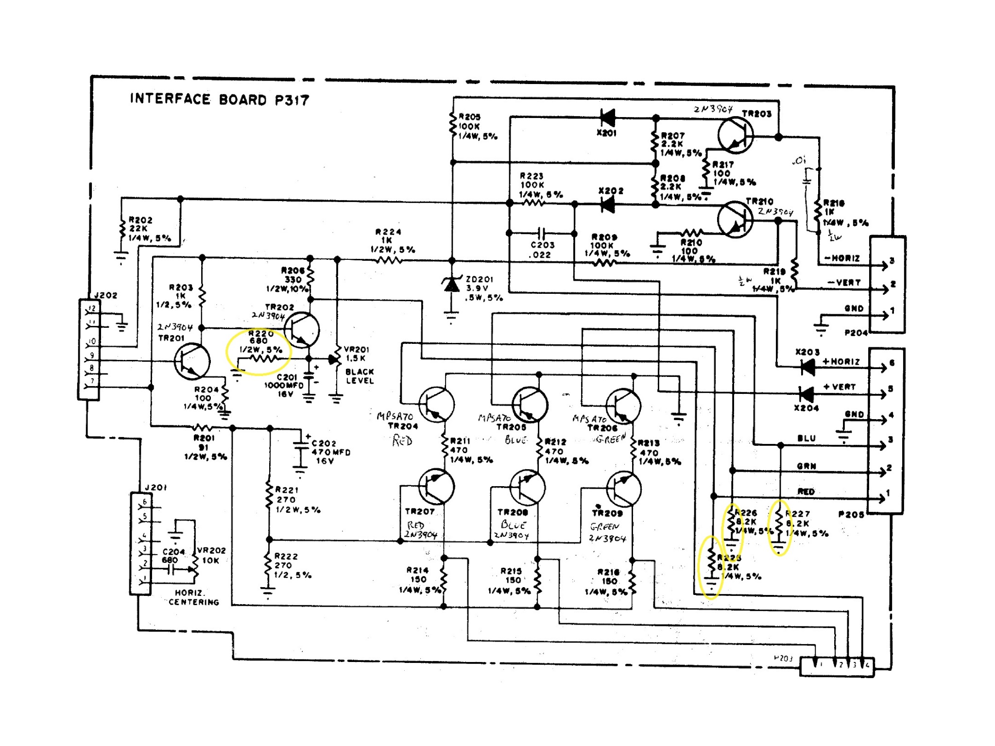
The original video input board was a P305 and the spare a P306. The two were identical aside from different resistors in the colour pre-amplifiers. From prior restoration I'd already figured out that the P305 was incompatible with the Lazarian board output and a few years ago had fitted 10K ohm pull downs on the video inputs to get something working. I remembered that at the time it was difficult to get a good picture. Looking again at how the WG4900 video input circuit compares to the WG4600 input circuit I found two main differences - the WG4900 had 3 x 8.2K Ohm pull down resistors on each video colour input and a 220 Ohm resistor across the black level adjustment pot (used to adjust the brightness). A little bit of research discovered that a WG4600 P317 video input board exists that has these similar components fitted in the areas matching the WG4900 input circuit. On the P317 the black level resistor was a 680 Ohm with 3 x 8.2K Ohm on the video inputs. The plan was to fit the four resistors onto the P305 & P306 to make them into P317's.

|
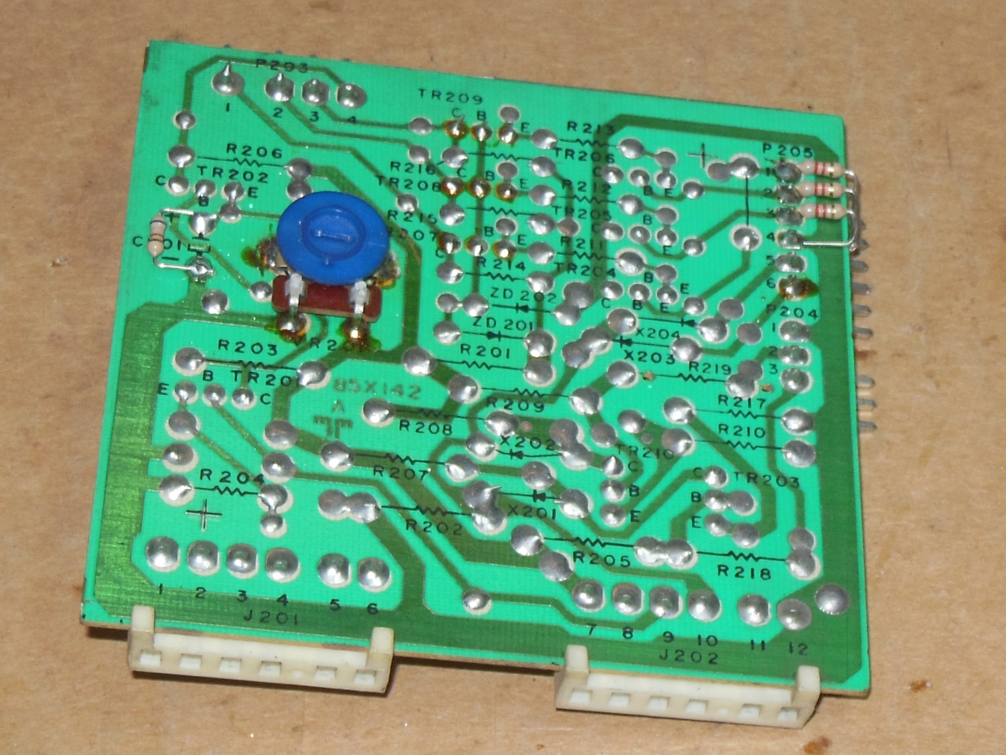
The resistors were fitted on the solder side of the PCB and the black level pot flipped onto the back side to allow easier adjustment when fitted in the chassis (a suggestion from the repair party).
|
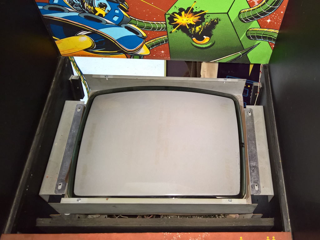
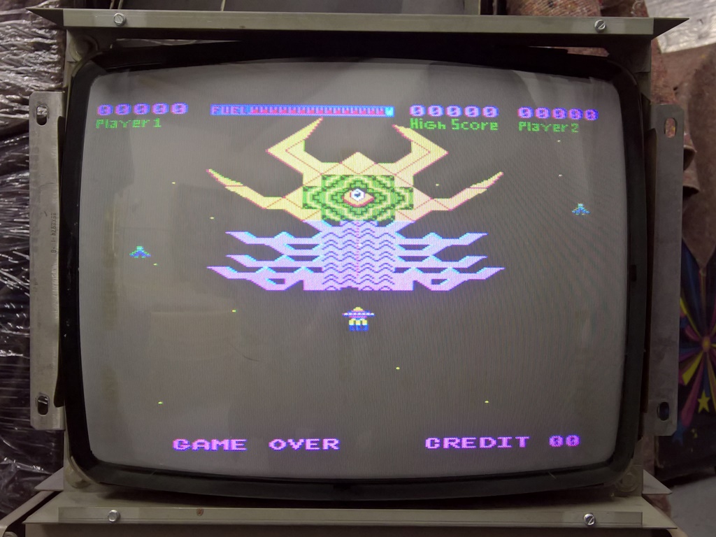
Retesting this time found no issue with the picture and the brightness was stable and easily adjustable. After a few hours of run time the monitor was fitted back into the cabinet.
|
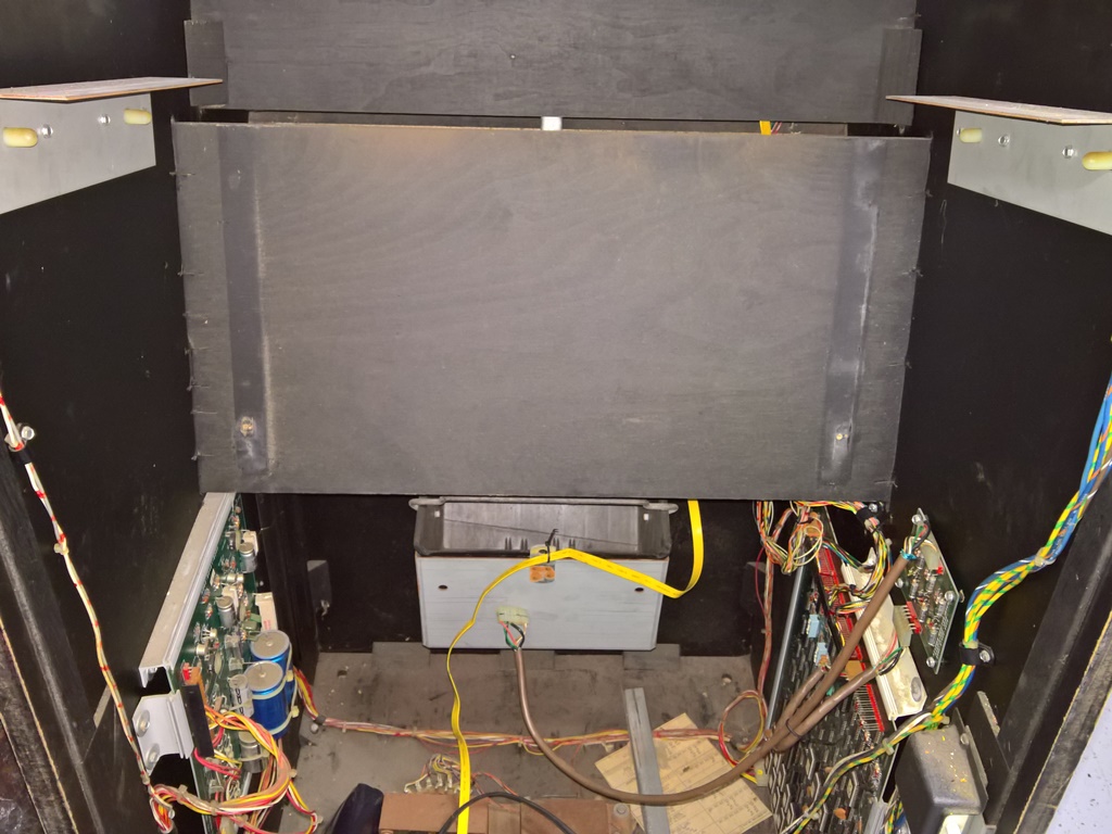
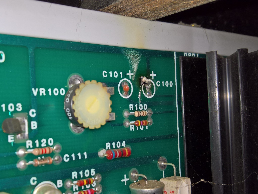
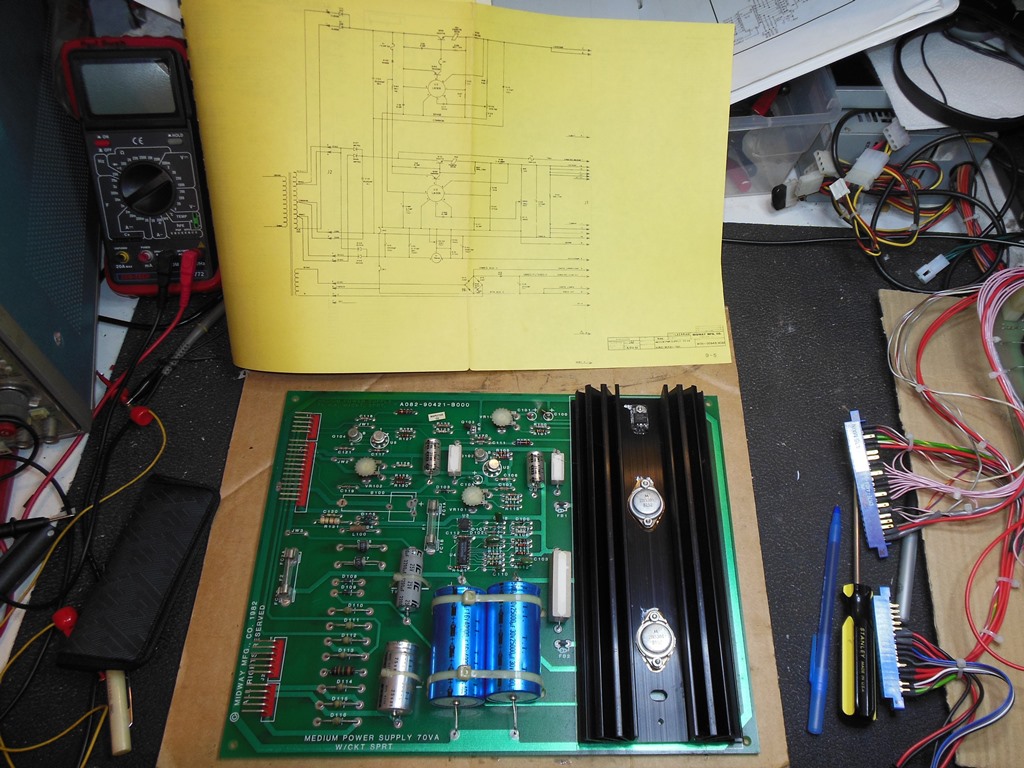
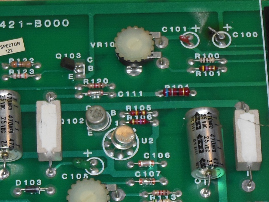
Whilst reinstalling the chassis I noticed a blown capacitor on the power regulator board. The capacitor itself had almost completely burned away (leaving a smoke trail above), likely a while ago. I made mental note pull it for repair after retesting the monitor.

|
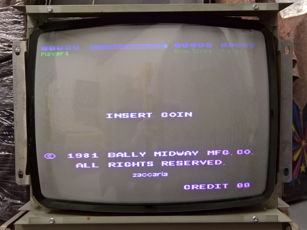
Back in the cabinet the monitor was still working properly with a nice clear bright picture. In game mode, however, neither move left or fire left was working that I surmised was likely a bad connection disturbed by the monitor work.
|
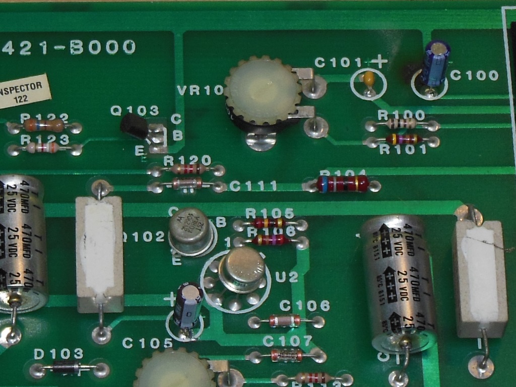
In addition to the tantalum capacitor that burned out there were two other tantalum capacitors that I decided to also replace at the same time. Tantalum capacitors are prone to failing with shorts (often shorting out a power rail or burning up like this one did) so I steer clear of using them. On this board I used two equivalent value & higher voltage rated electrolytic capacitors and one non-polarized ceramic to replace them.
|
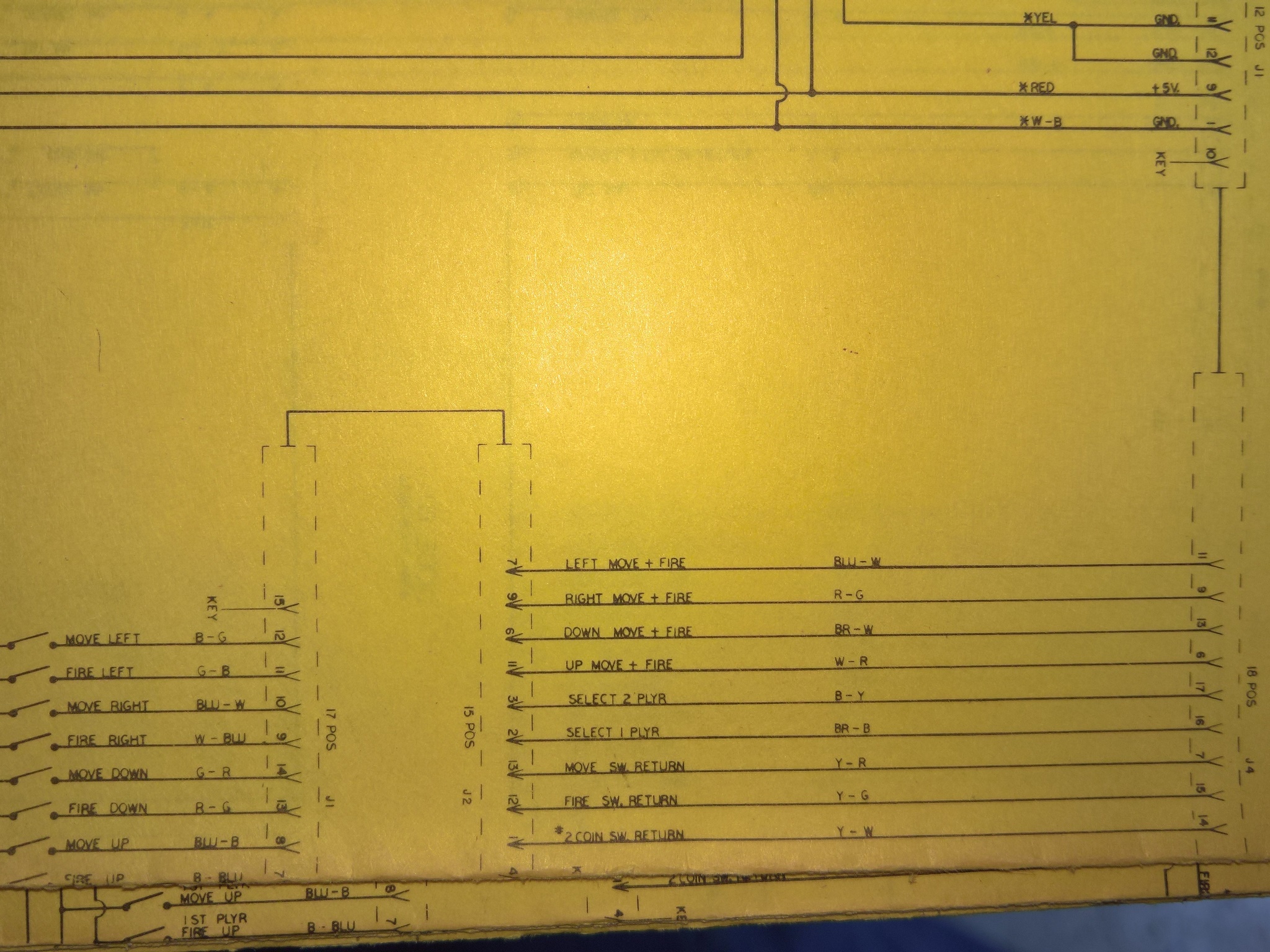
Like other Zaccaria games of the same era, Lazarian uses a matrix input scheme. In native Zaccaria cabinets one side of each control switch is connected to an output from the board (instead of ground) via a diode mounted onto the switch. Midway instead ran the control signals to one side of a separate diode board and then connected the control panel switches to the other side, presumably to negate the need to attach diodes to the control panel switches themselves. This arrangement also makes it a more complicated to test the control wiring since one side of the switch isn't grounded.


|
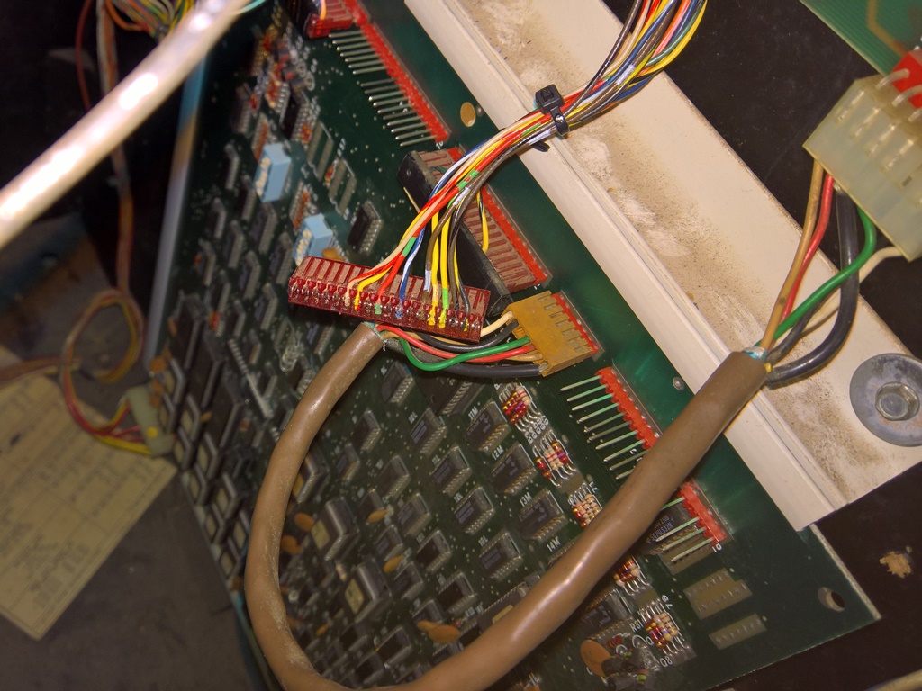
Working back from the control panel I unscrewed the diode board and found several dry solder joints so I removed the board, reflowed all the solder joints and tested all the diodes (they were all working OK). Back in the cabinet there was still no left.

|
Next I investigated the game board side of the control wiring and found that the blue-with-white-stripe left input wire wasn't properly secured in the IDC pin of the connector housing. Using a fine screwdriver blade I pushed the wire further into the pin. Both lefts were now working reliably again.

|
With the controls fixed the game was ready for the next show :)