|
|
|
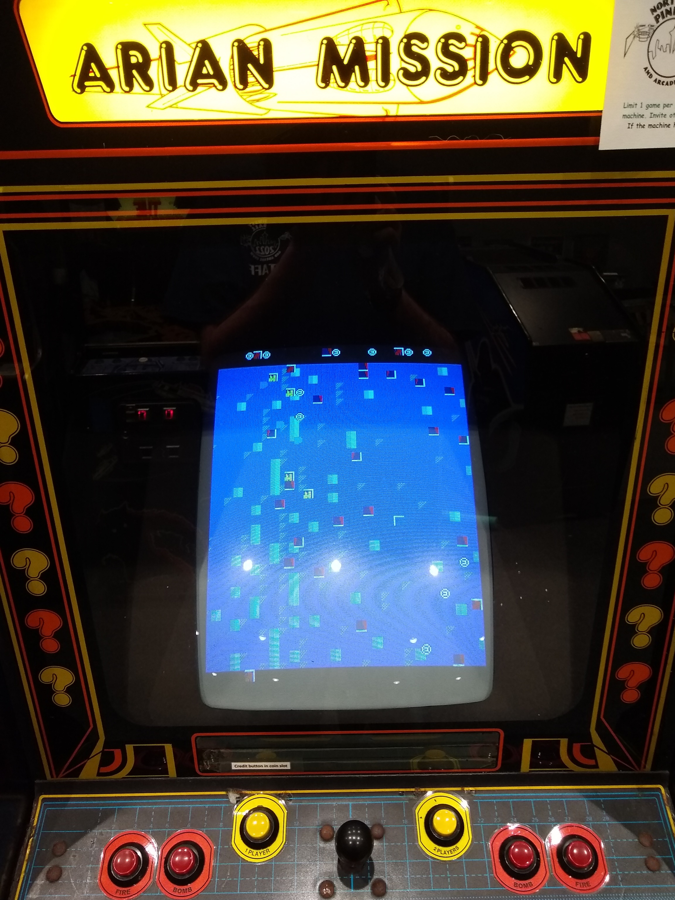
The game ran OK through most of Thursday but eventually stopped booting. A spare game PCB was swapped in that continued running OK for the remainder of the show.
|
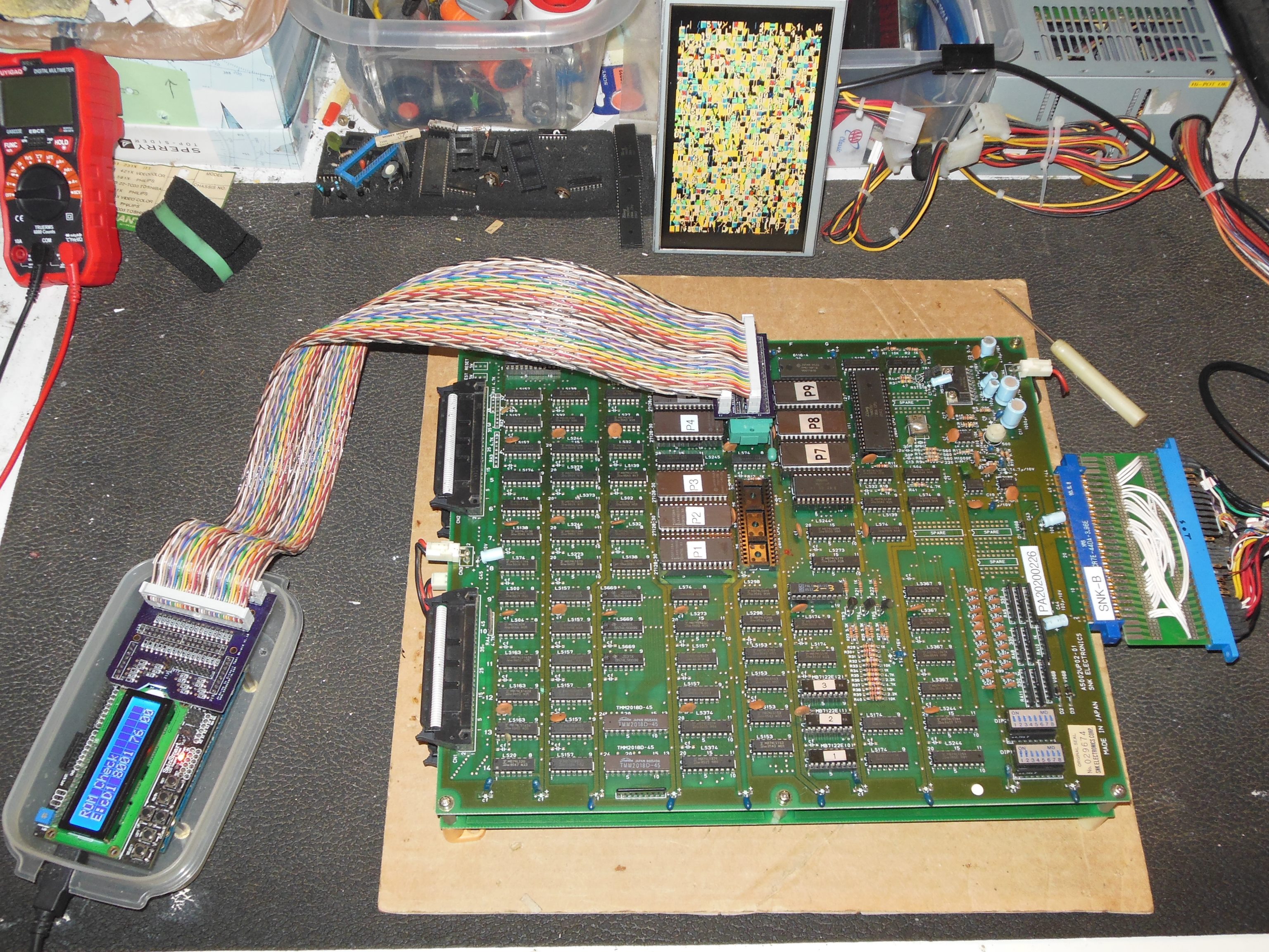
Jumping straight in the with the Arduino ICT found:
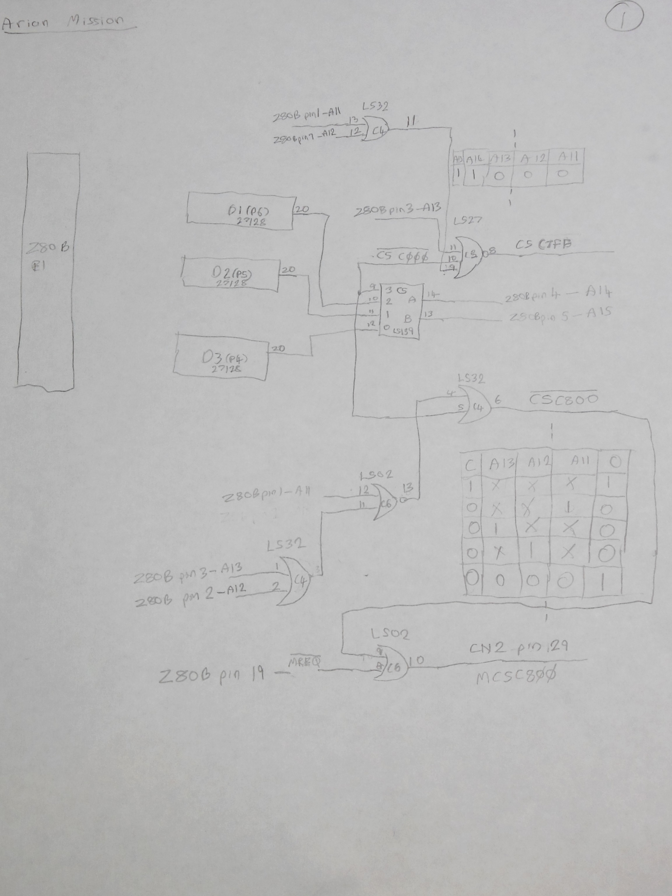
There were no known schematics for this PCB set with the closest being a poor scan of the older game Marvins Maze that provided a rough guide to how the two CPUs are connected up to the shared memory space. Each fault-finding step ended up as two parts - tracing the relevant portion to build the schematic and then using the scope with Arduino ICT to inspect the signals.
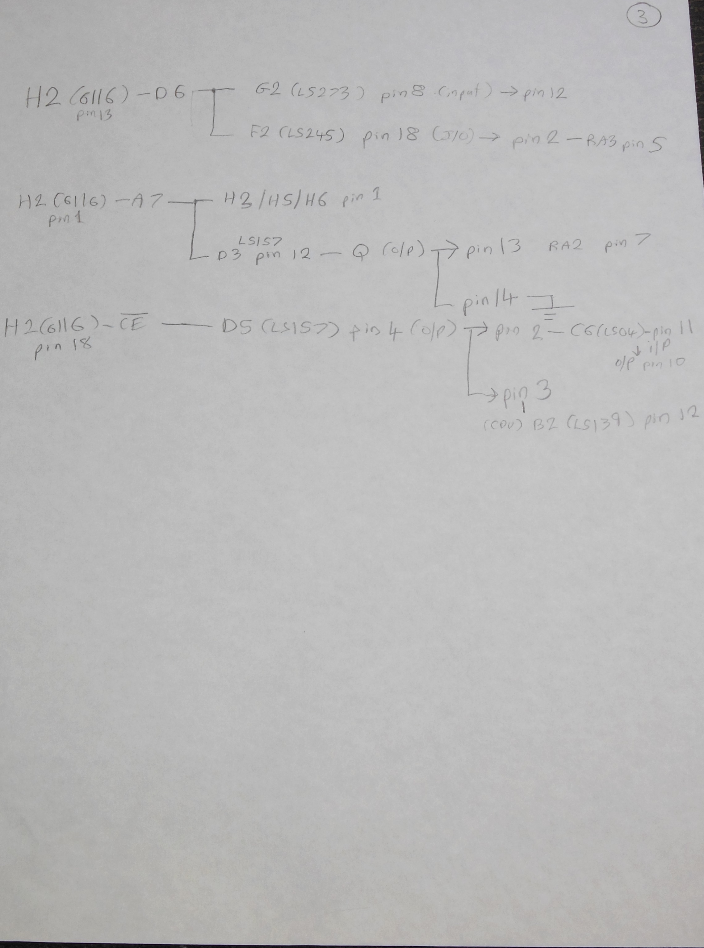
The buffers & latches on the CPU PCB along with Marvins Maze schematics and measuring with the scope during Arduino ICT RAM operations identified the common address bus leaving the video PCB as a 12-bit bus present at unpopulated resistor arrays RA1 & RA2. The common data bus was present at RA3.
After a "RAM Write All AD" to write data == address the RAM on the video PCB was inspected with the scope:
| Pin 1 - A7 | idle lo | | | Pin 24 - Vcc | idle hi |
| Pin 2 - A6 | idle lo | | | Pin 23 - A8 | idle lo |
| Pin 3 - A5 | active | | | Pin 22 - A9 | idle lo |
| Pin 4 - A4 | active | | | Pin 21 - ~WE | idle hi |
| Pin 5 - A3 | active | | | Pin 20 - ~OE | idle lo |
| Pin 6 - A2 | active | | | Pin 19 - A10 | idle lo |
| Pin 7 - A1 | active | | | Pin 18 - ~CE | active |
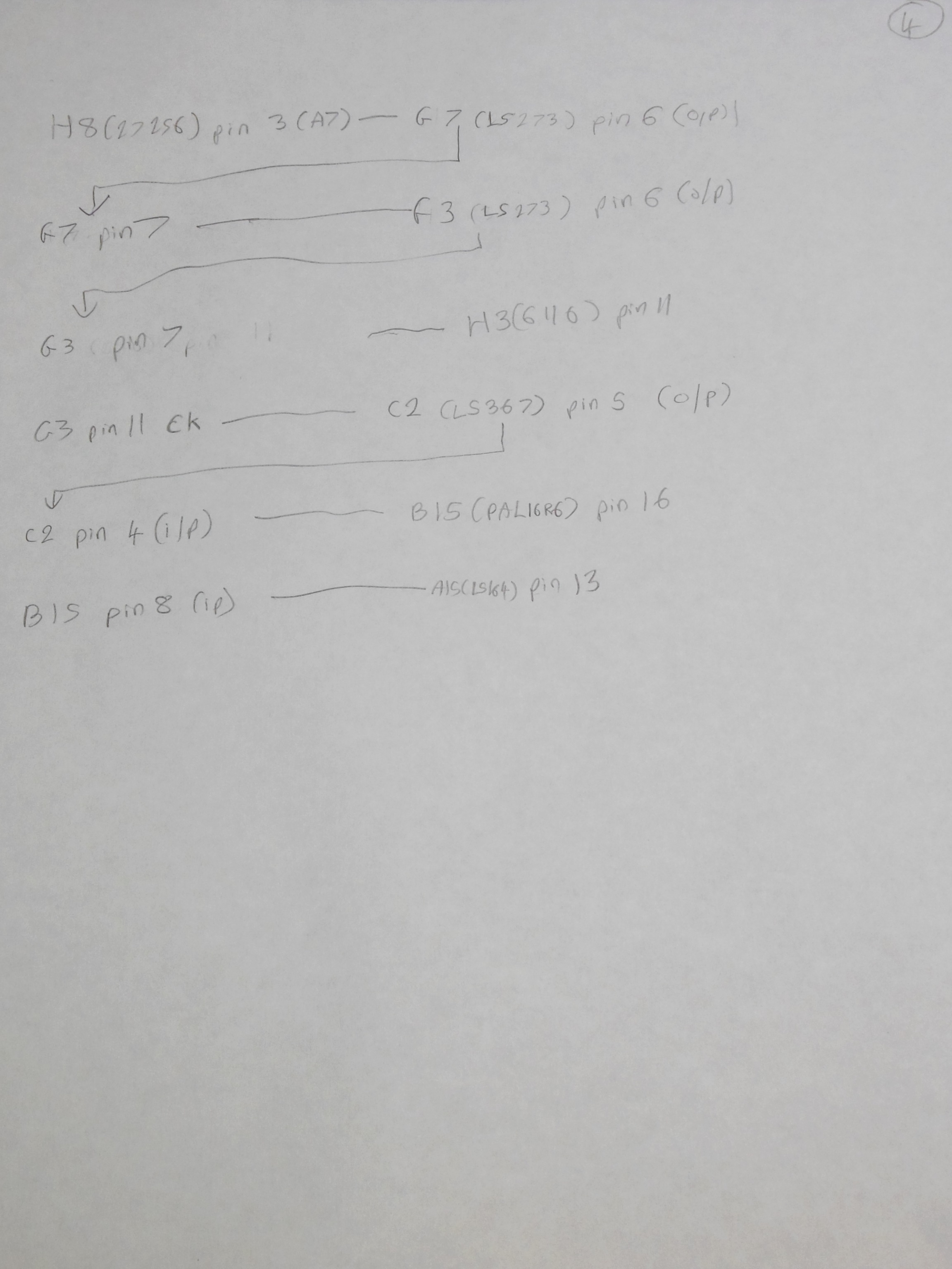
At this point I realized that the new failure syndrome may be easier to trace - why was there no video display? The power on state of the RAM did provide at some active data bus bits on IC H2 to work with. Checking IC H8 (27256):
|
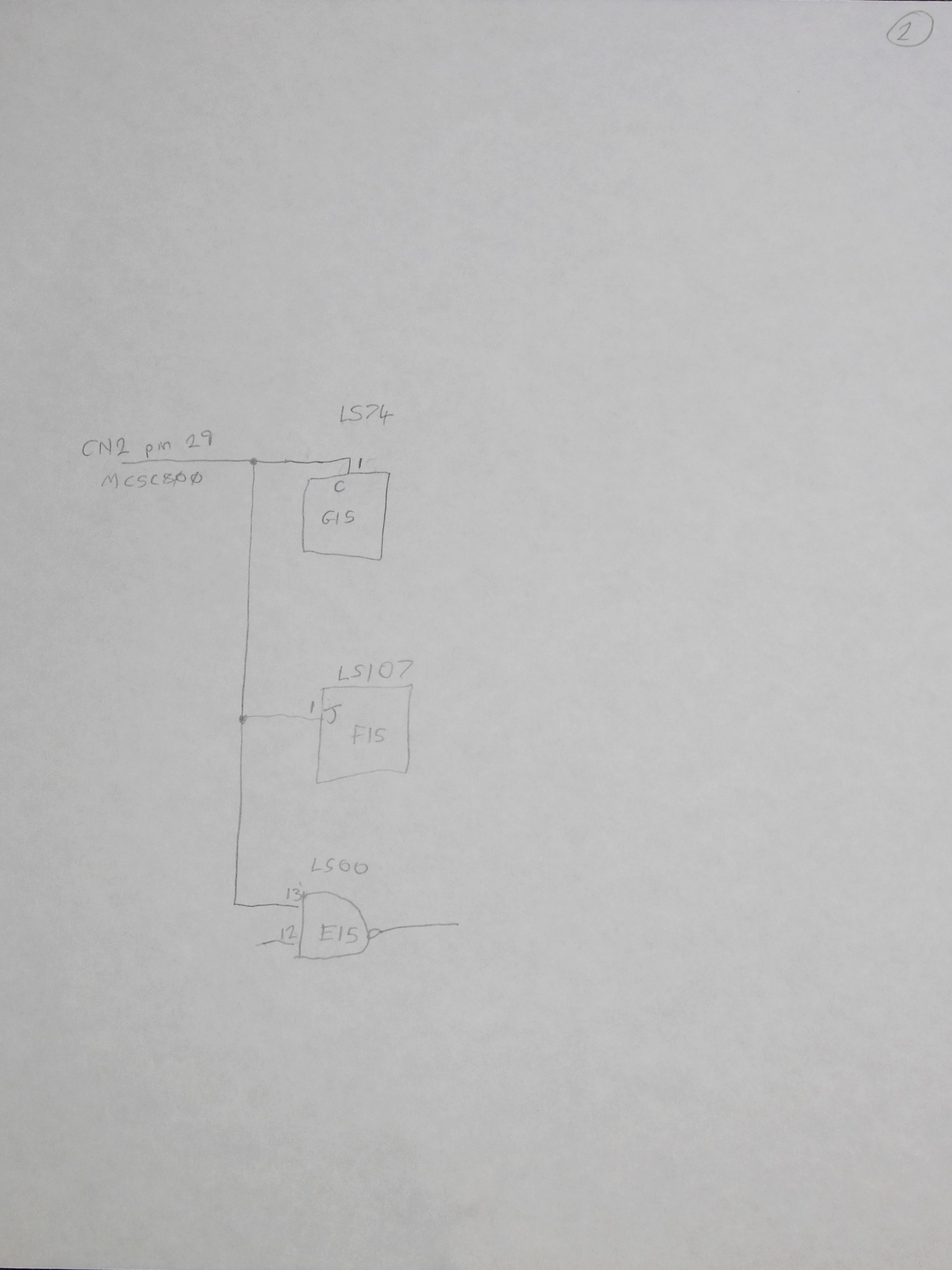
The schematic notes were captured for future use.
|
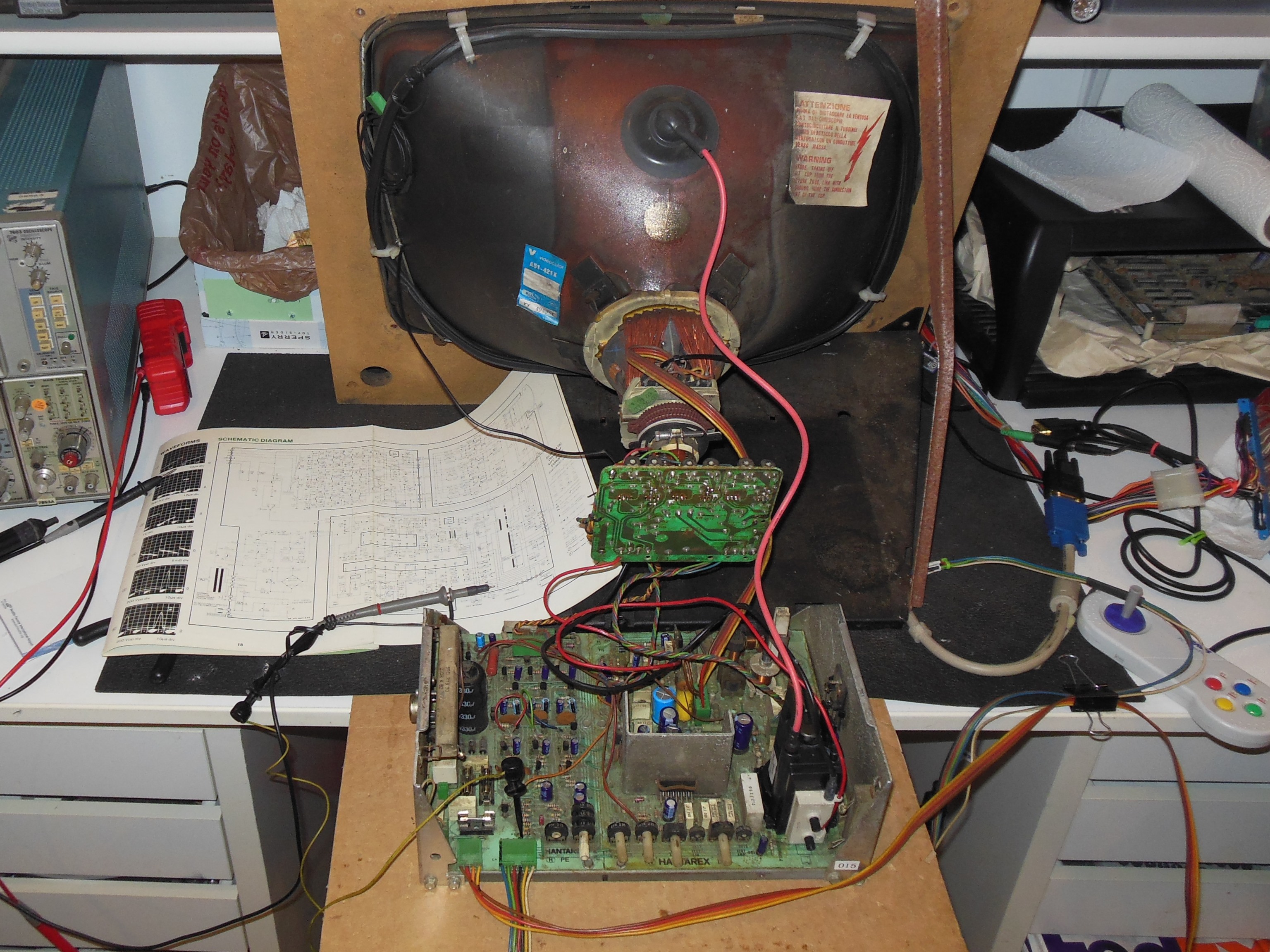
Pre-show testing found a intermittently vertical rolling picture and the vertical sync pot was adjusted all the way to one side as the closest lock. The chassis was removed and setup on the bench where it also had vertical roll. Checking TR1 (BC237) output on a scope didn't reveal any issue (a common failure point). The vertical sync pot RV15 (220K) track measured 860K in circuit, suggesting it was bad. Removing RV15 and measuring out of circuit found the resistance between all pins around 1M to 2M confirming it was bad. After replacing it the vertical lock point was approximately pot centre and the chassis was declared fixed.
|
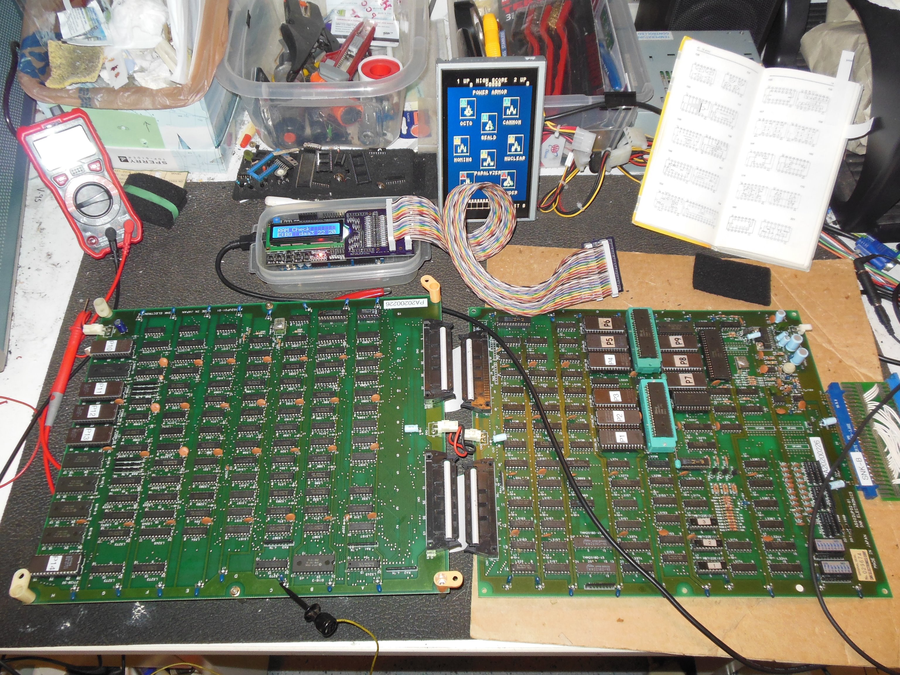
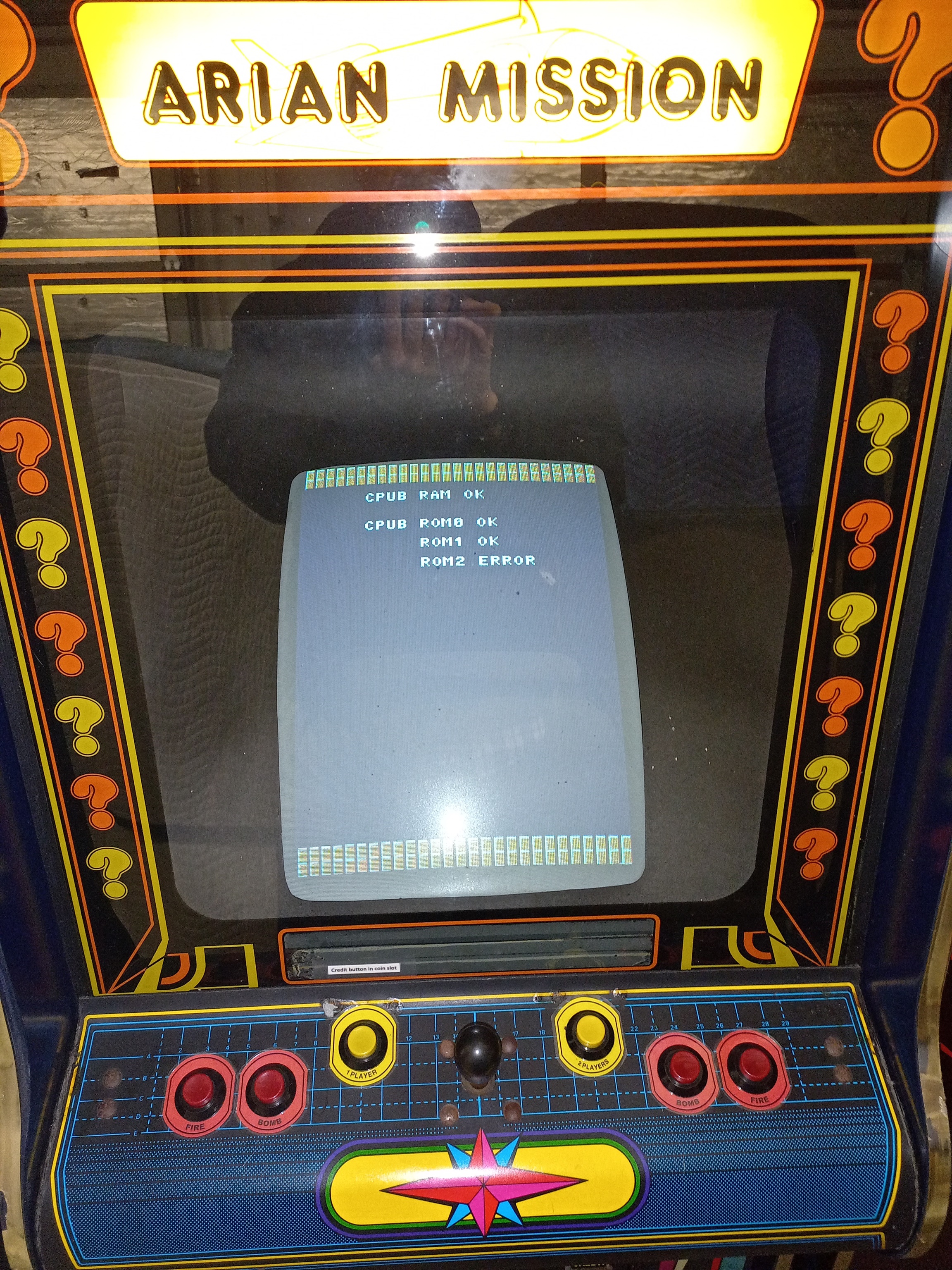
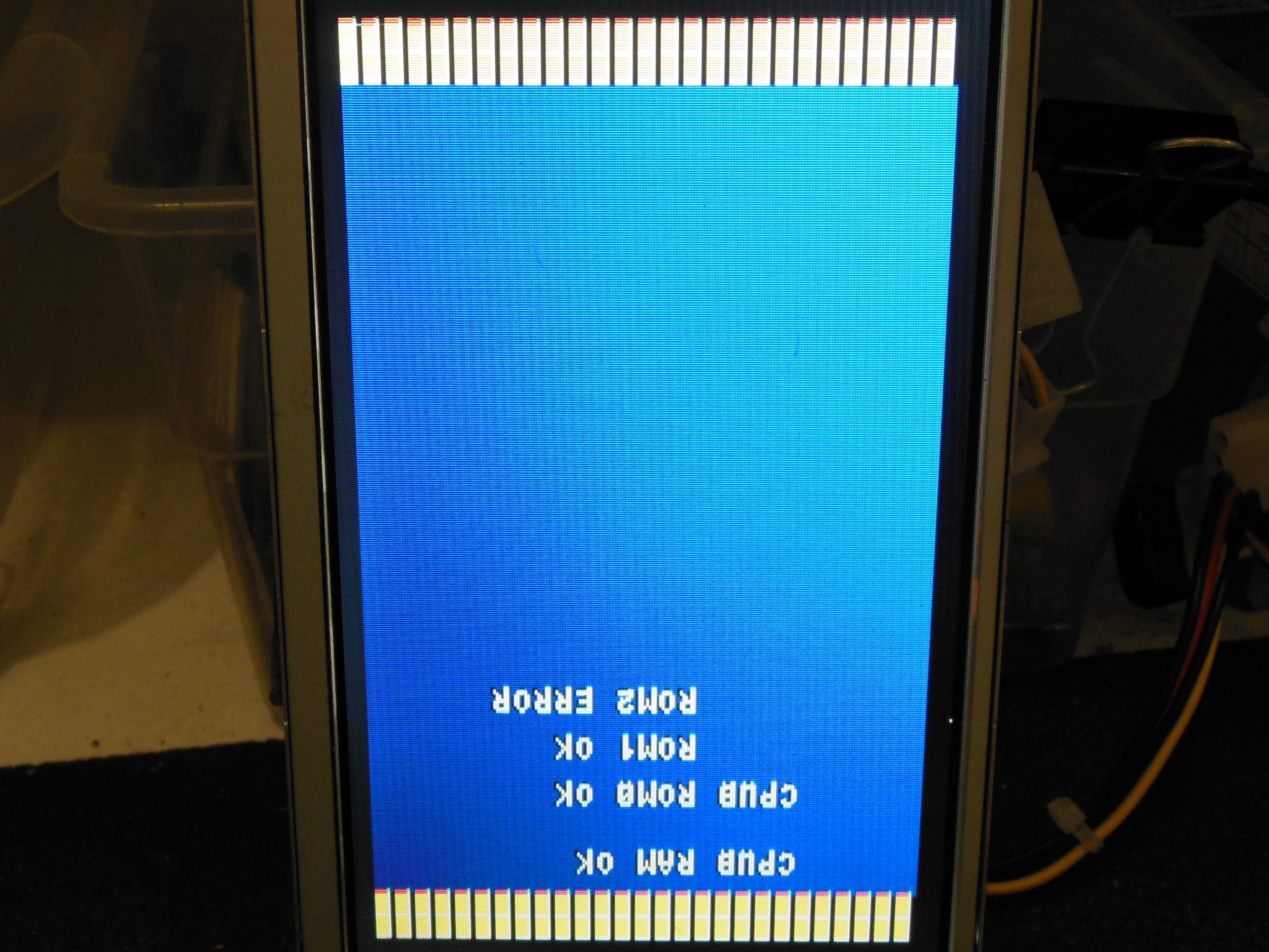
Pre-show testing found the game PCB not booting with a "CPU B ROM 2 ERROR" self-test failure. The game PCB was removed for repair.
|
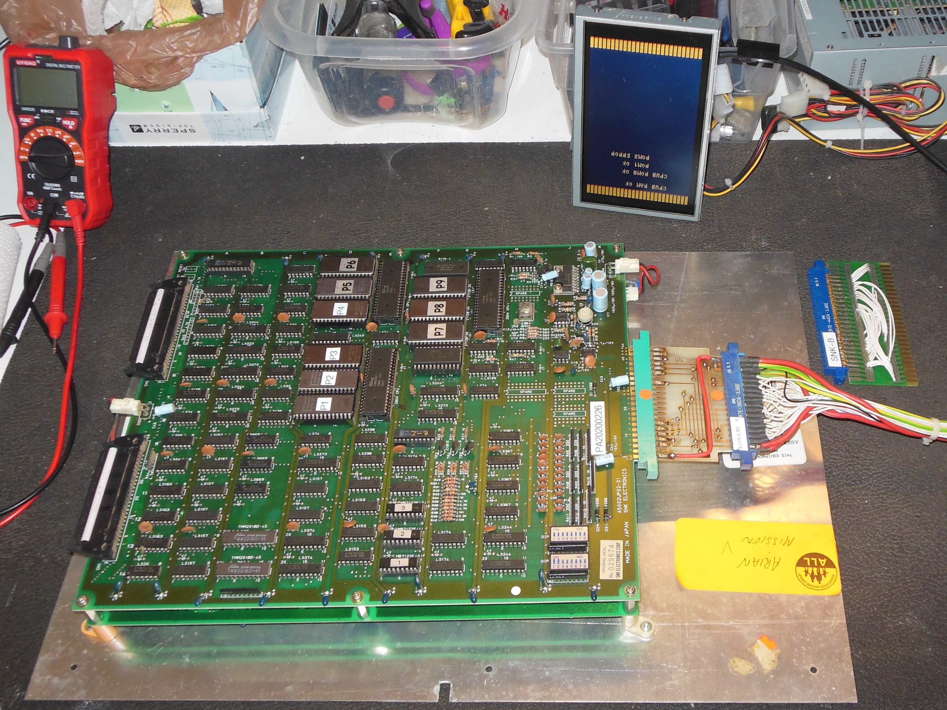
Which ROM was ROM2? Removing IC D1 (27128, P6) didn't change the error. Removing IC D2 (27128, P5) resulted in a ROM 1 error. After reinstalling the all the ROMs back into the PCB, the PCB reported a ROM 0 error and crashed. Checking the pins found IC D1 and D2 pins corroded and after a cleaning the game ran reliably.
|
Whilst the game PCB now booted and played OK, there was still a minor sprite graphics corruption issue that was left as is.
|
The repaired monitor chassis and game PCB were fitted back into the cabinet and tested OK.