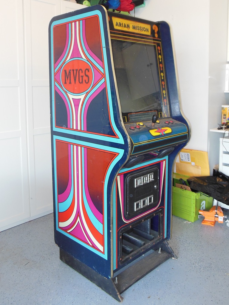
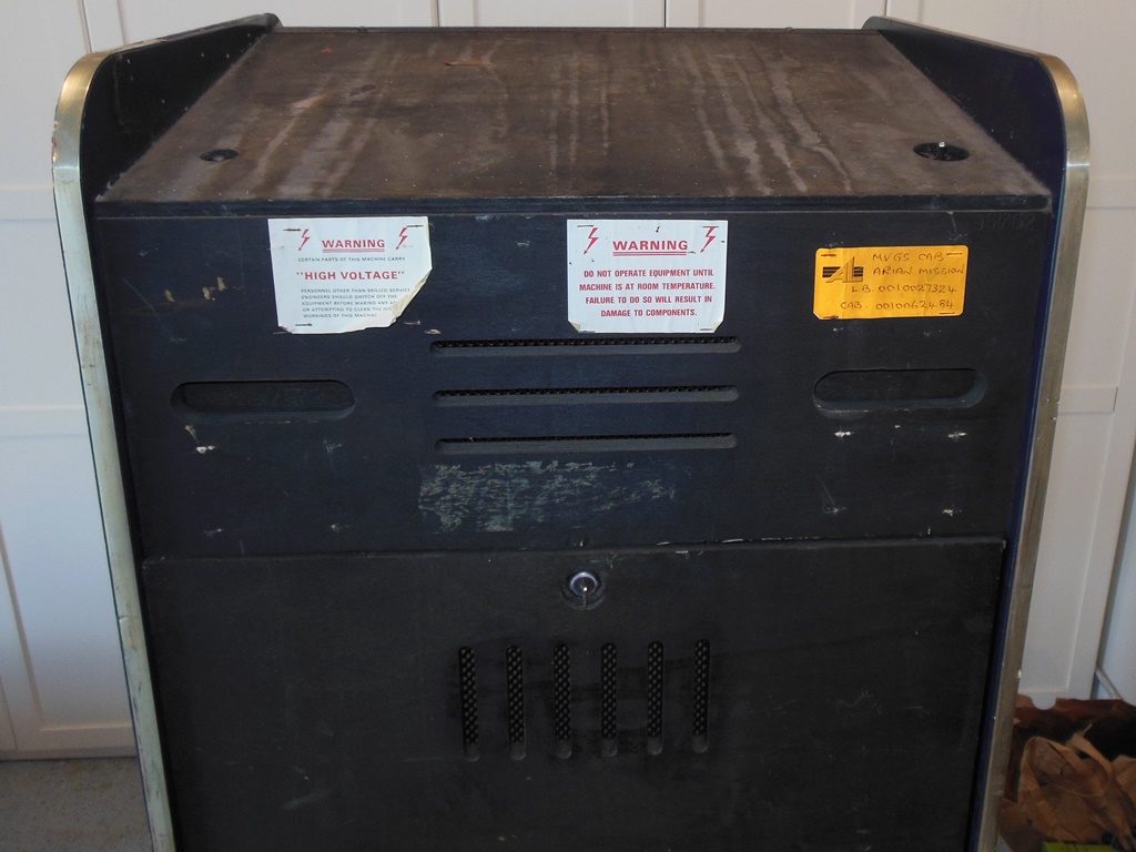
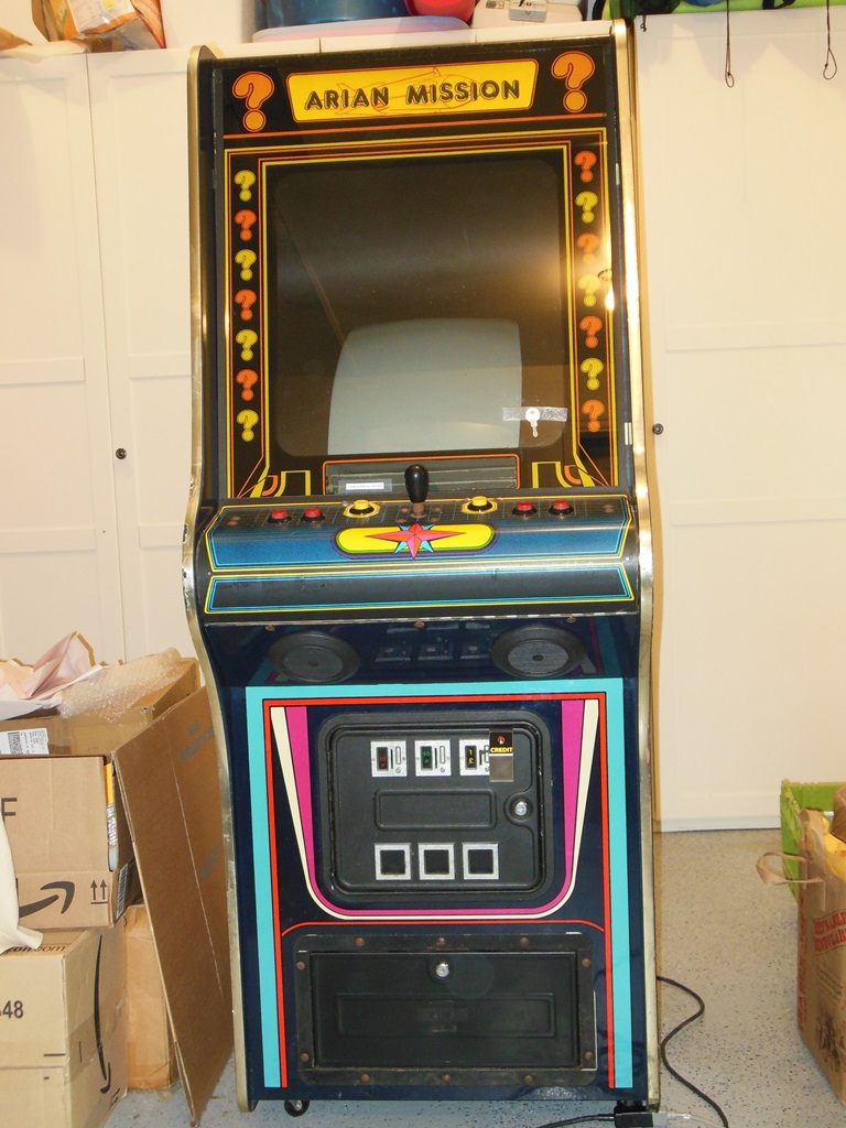
This cabinet was acquired in the UK and came over to the US as part of The Big Move.
|
|
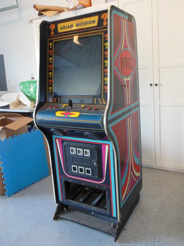
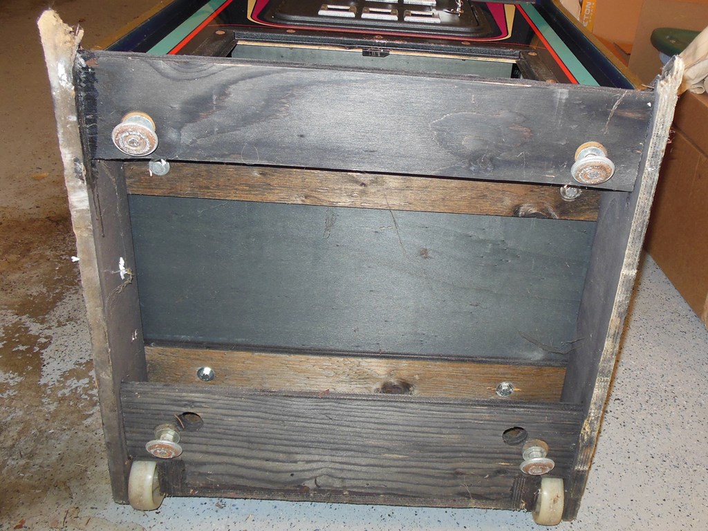
The general exterior condition looked pretty good. Some of the button collars were damaged or missing but the underlying overlay was in good condition. The cash box cover was missing and the foot rest base was damaged but the artwork was in reasonable condition except for scratches and dings here and there. The T-molding didn't fit too well and had a few damaged spots.
|
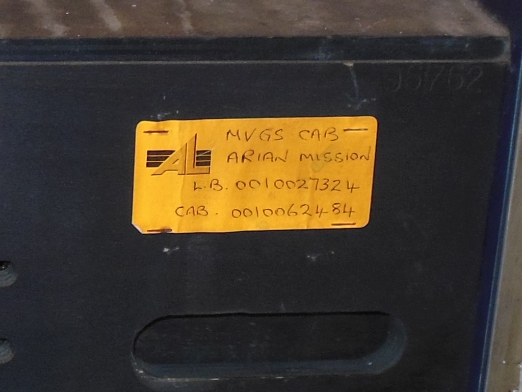
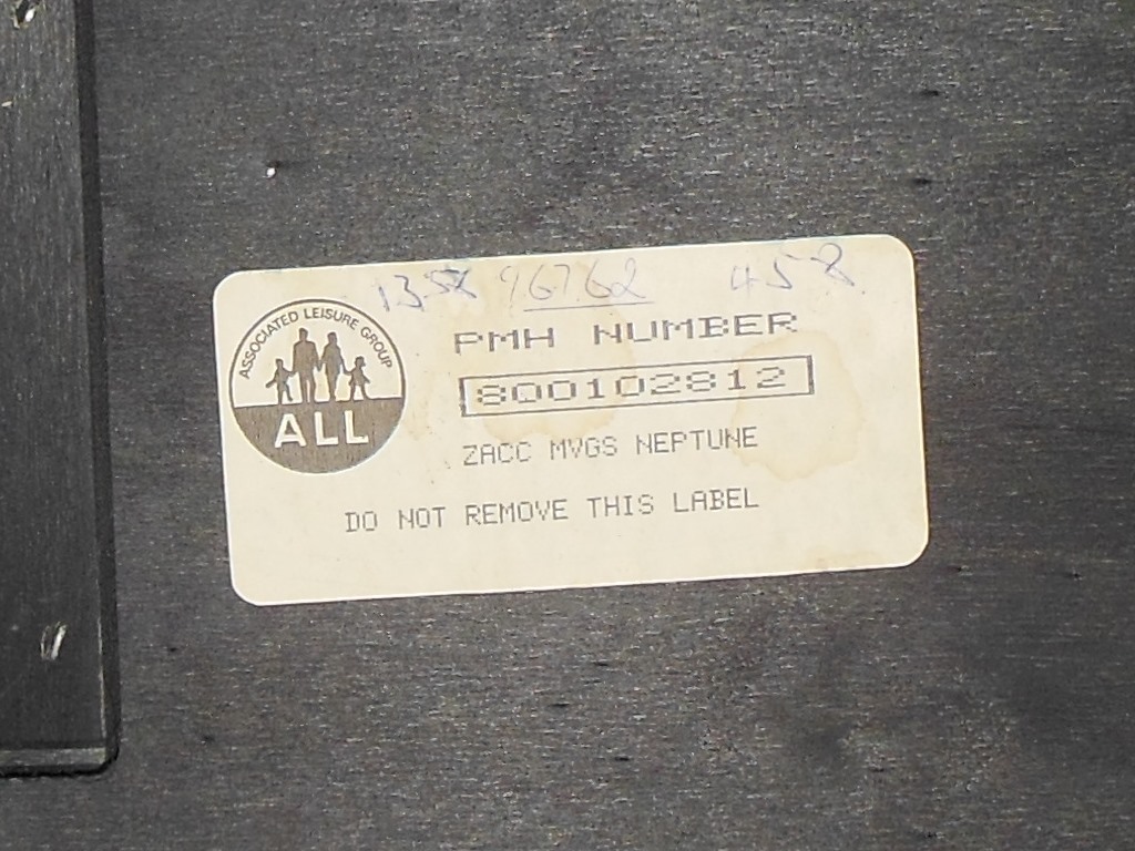
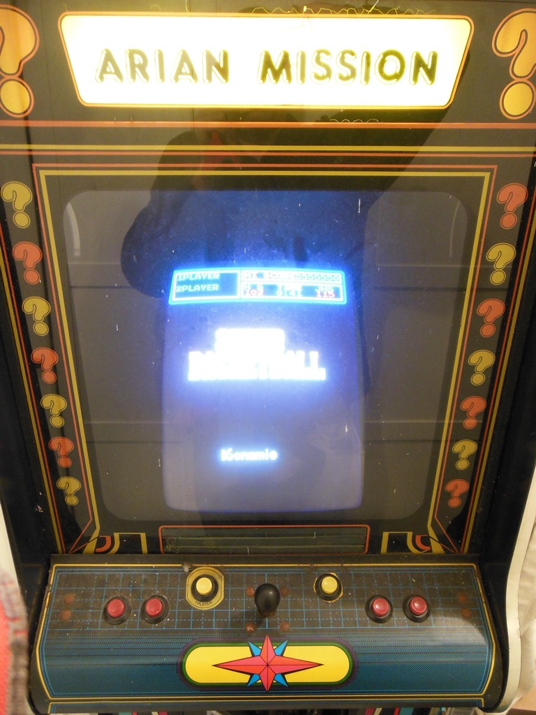
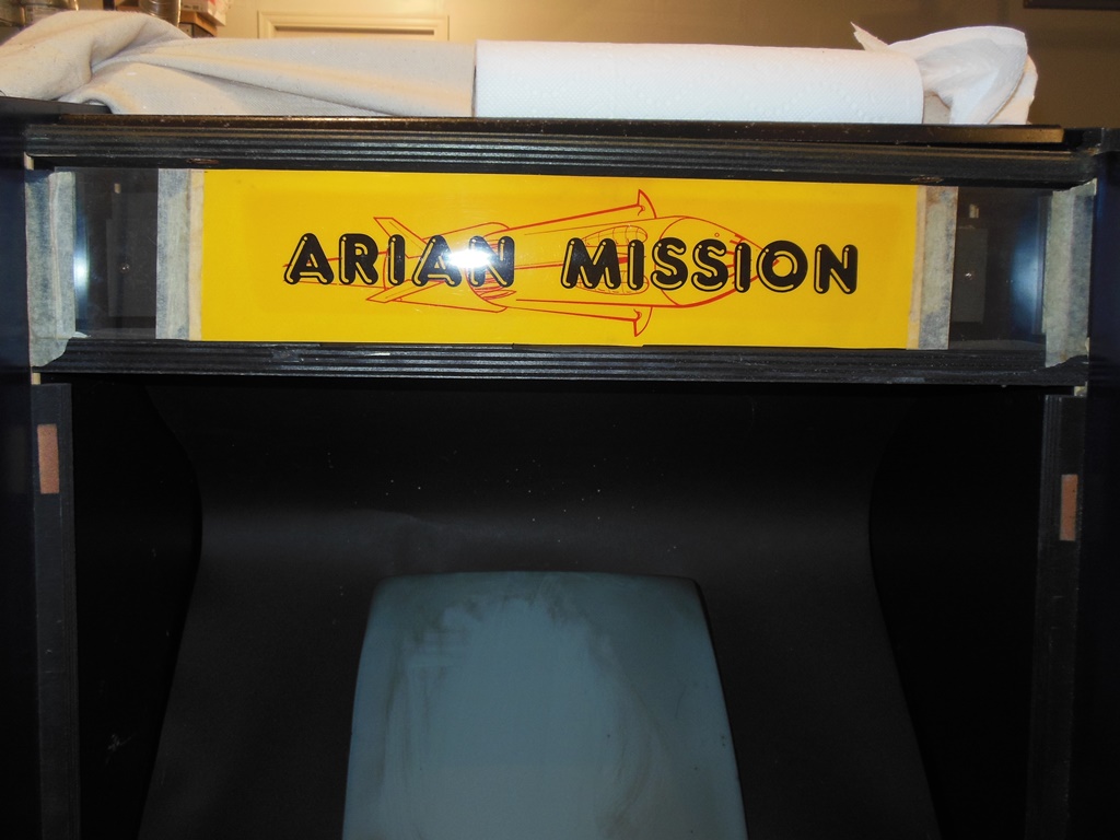
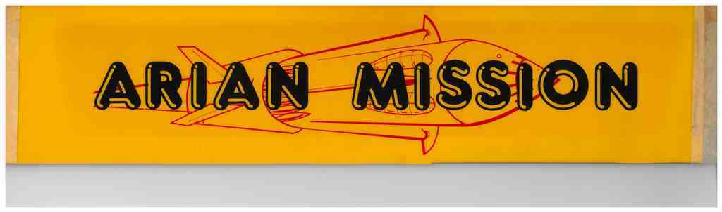
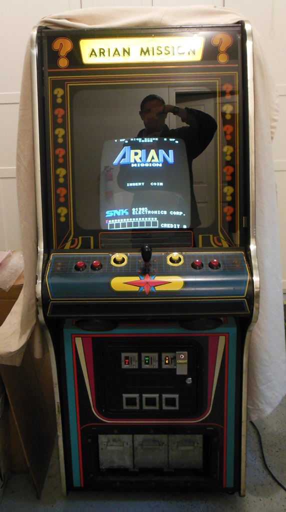
The back had a very nice original hand-written Associated Leisure label proclaiming the Arian Mission configuration of the cabinet. These were manufactured within a couple of years of JAMMA becoming standard so I consider it a rare find of an MVGS still in its original game configuration.
|
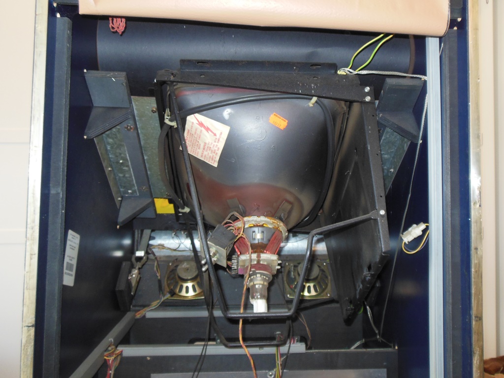
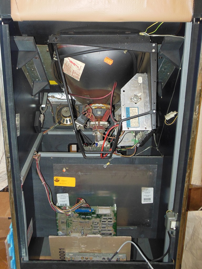
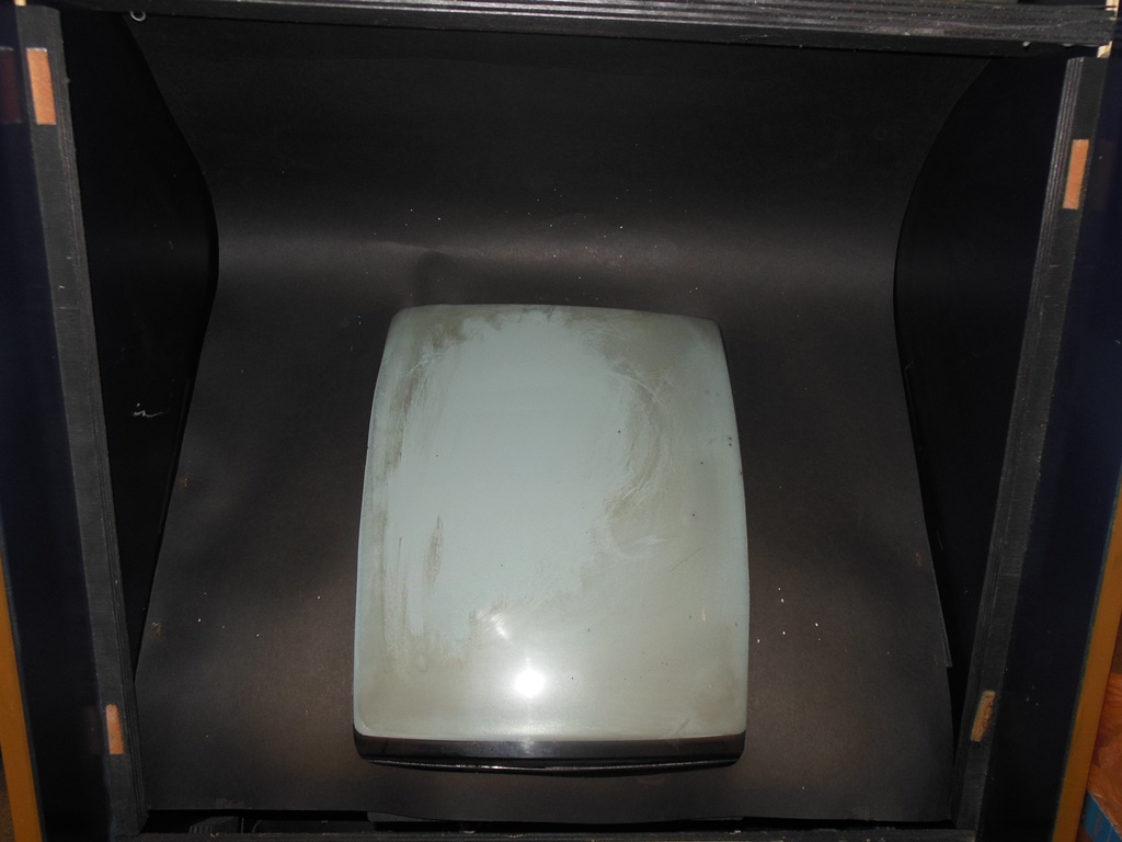
Clearly the monitor was missing the chassis, that would have been a Hantarex MTC-900E. Also note that the monitor has toggle switches fitted to allow the yoke coils to be swapped to accommodate flipping the picture. It looked like this was a fairly neat modification so I suspect it may have been either a Zaccaria factory or Associated Leisure modification. I choose to leave this as is.
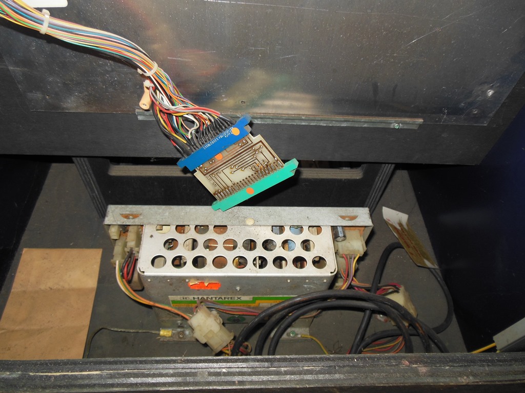
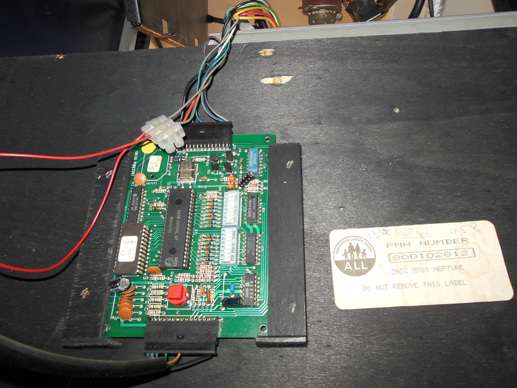
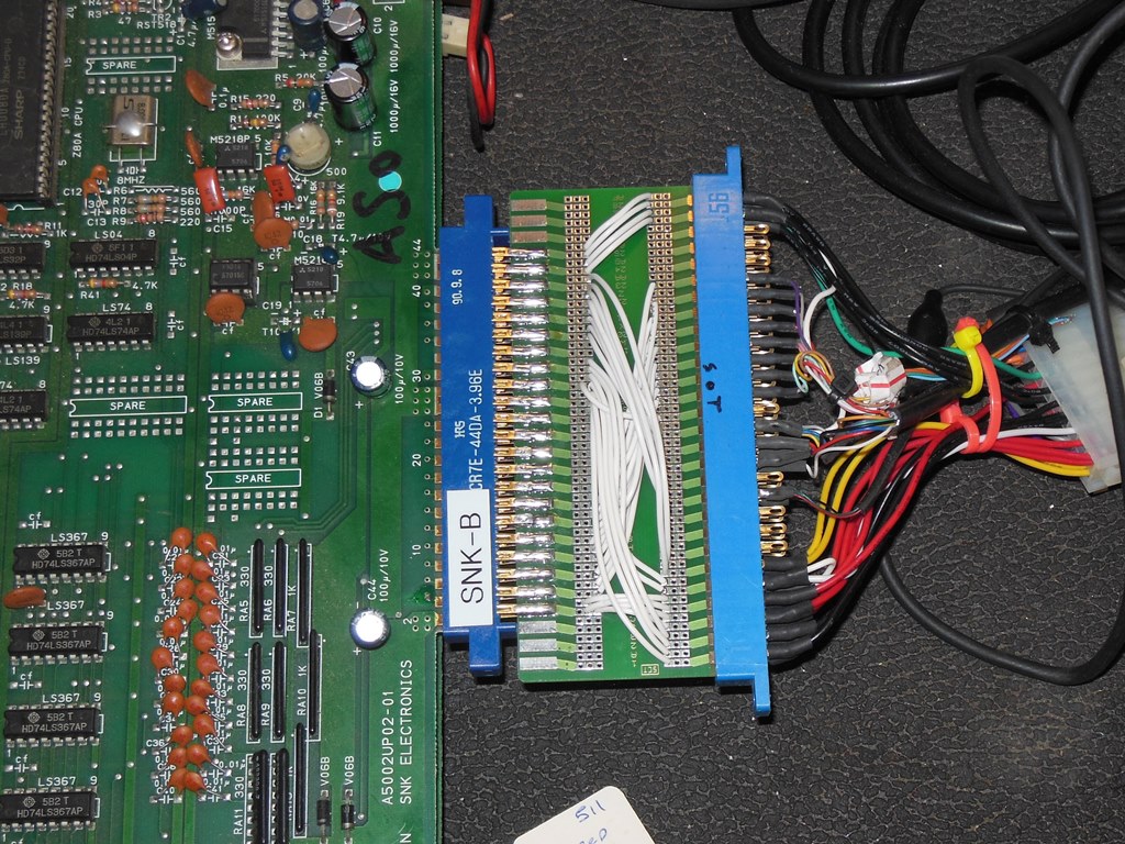
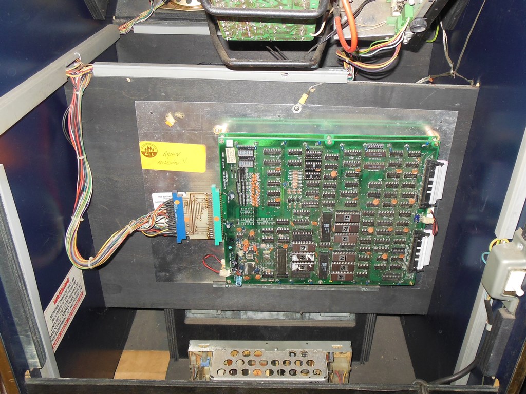
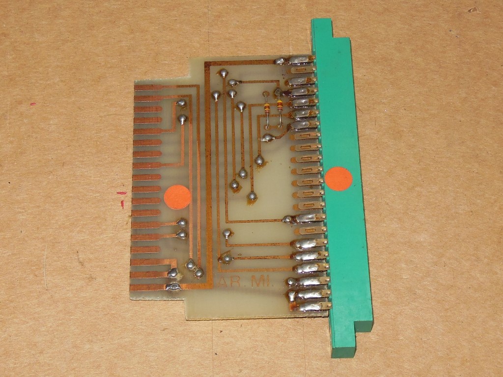
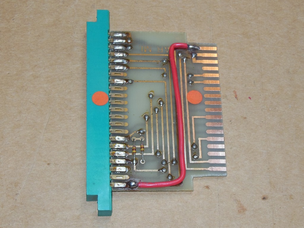
Also missing was the SNK Arian Mission game PCB. The Zaccaria Universal cabinets were built wired for the Konami wiring standard, so present in this cabinet is an adaptor PCB that converts from Konami to SNK. That the adaptor is still present saved me the task of having to build an adaptor myself :)
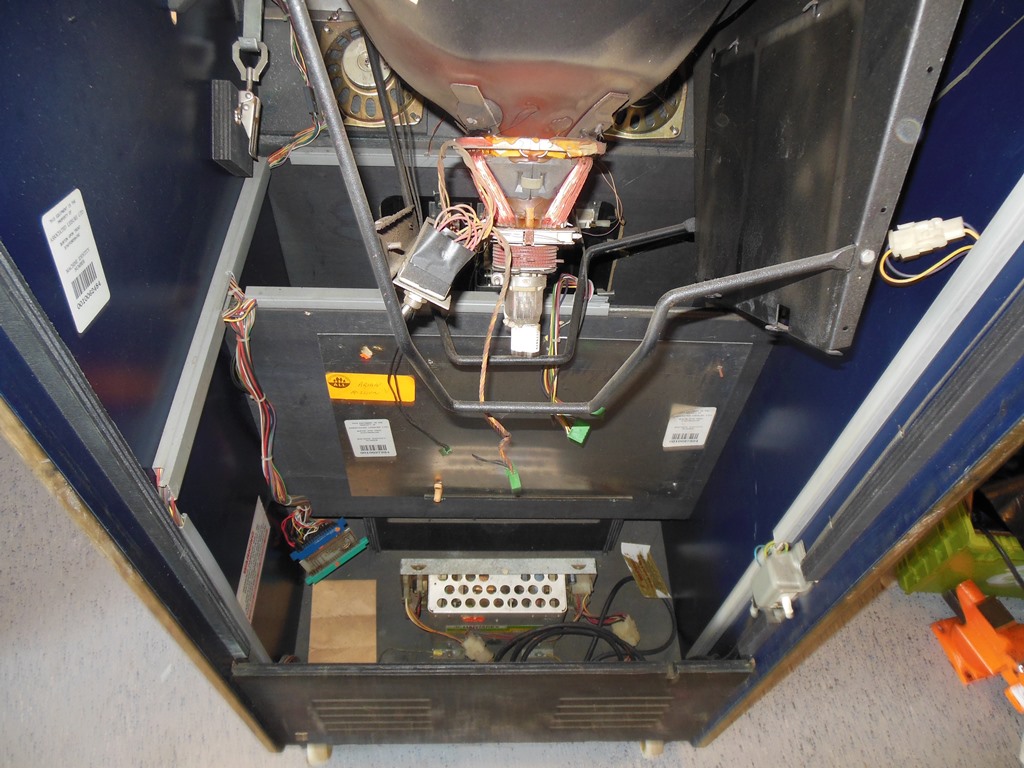
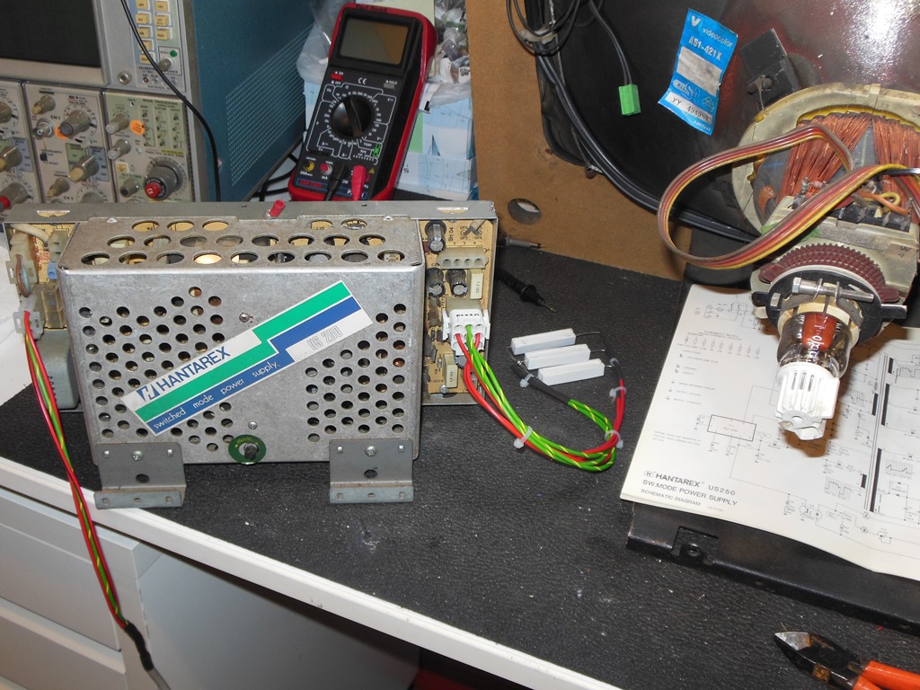
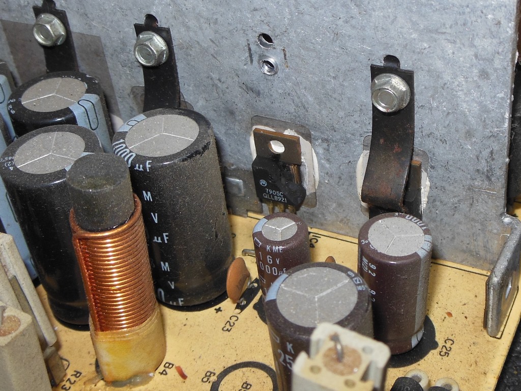
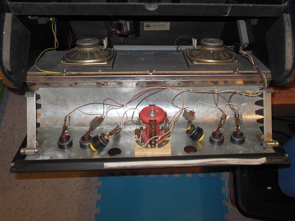
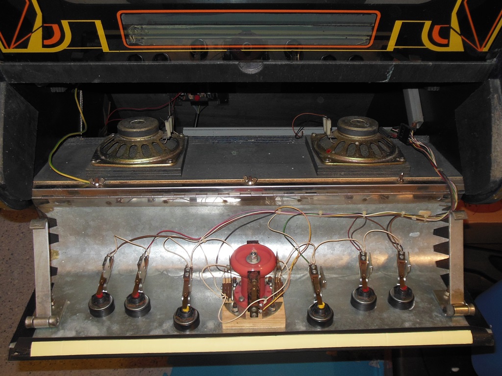
Unlike the other late style Zaccaria cabinets that use the IGR power supply, this cabinet was fitted with a Hantarex US250 switched mode power supply.
|
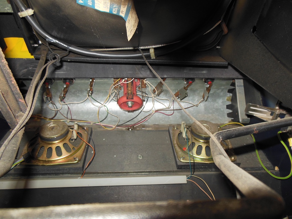
The control panel wiring looked complete, original and unhacked. Both the cash box and cash box door were missing but since these are shared with other cabs I had a spare door I could use to replace it. The coin door & slots all looked complete and original.

|
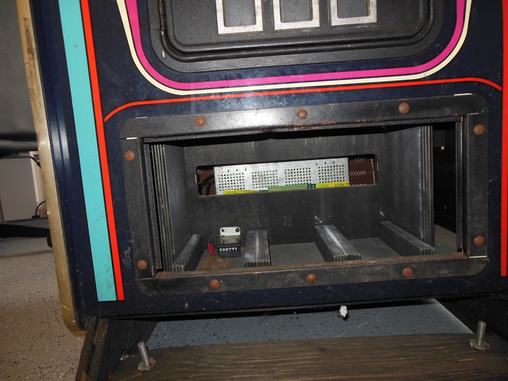
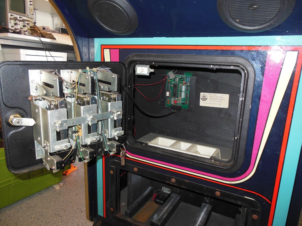
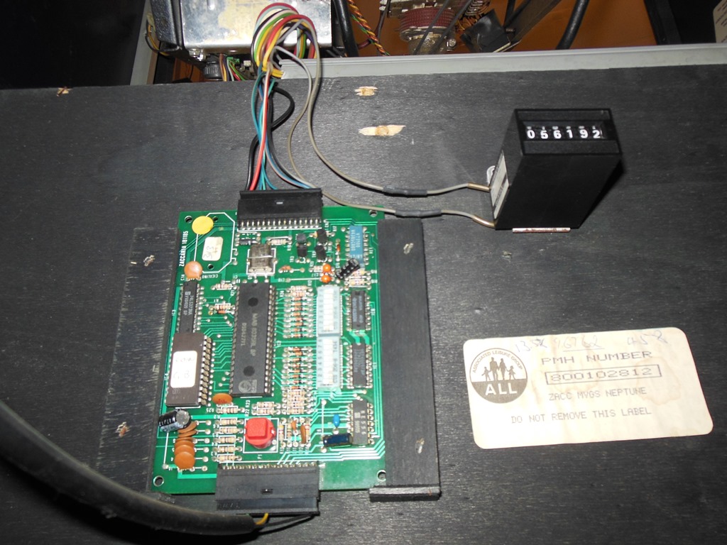
Inside the coin door was a very nice label naming the cabinet/configuration as "ZACC MVGS NEPTUNE", the name that I chose to keep (rather than the generic "Zaccaria Universal" factory name). Inside the coin door the 1B1185 credit PCB was present and unhacked except for an operator modification to move the coin counter from behind the coin door to behind the cash box door.
|
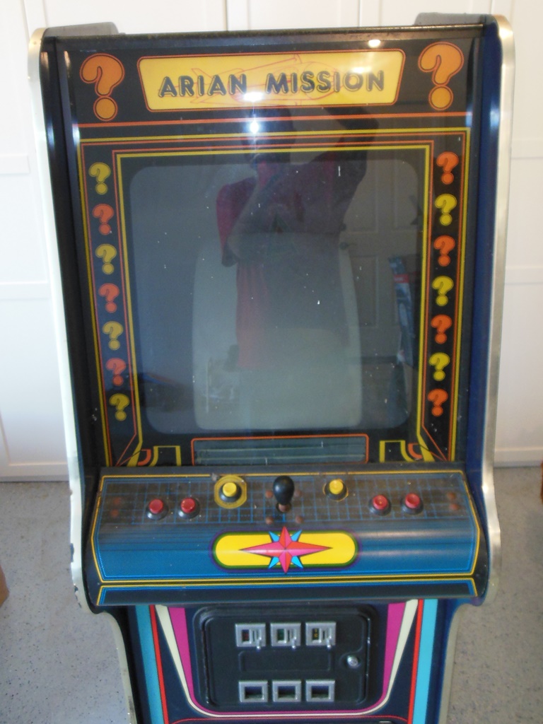
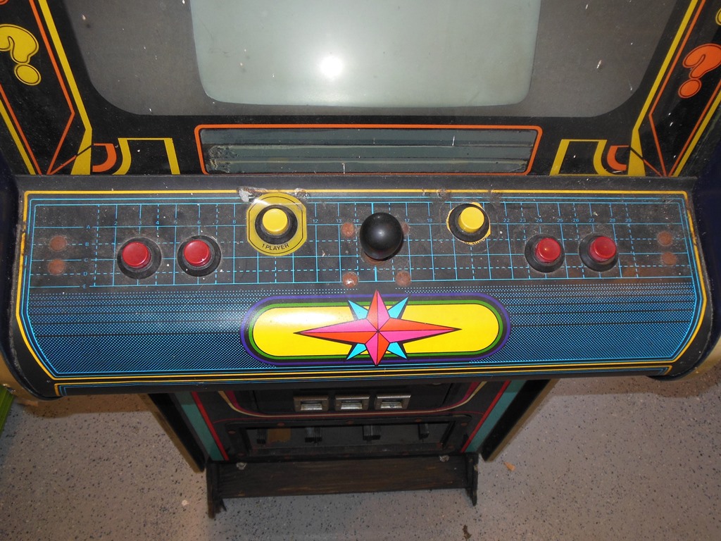
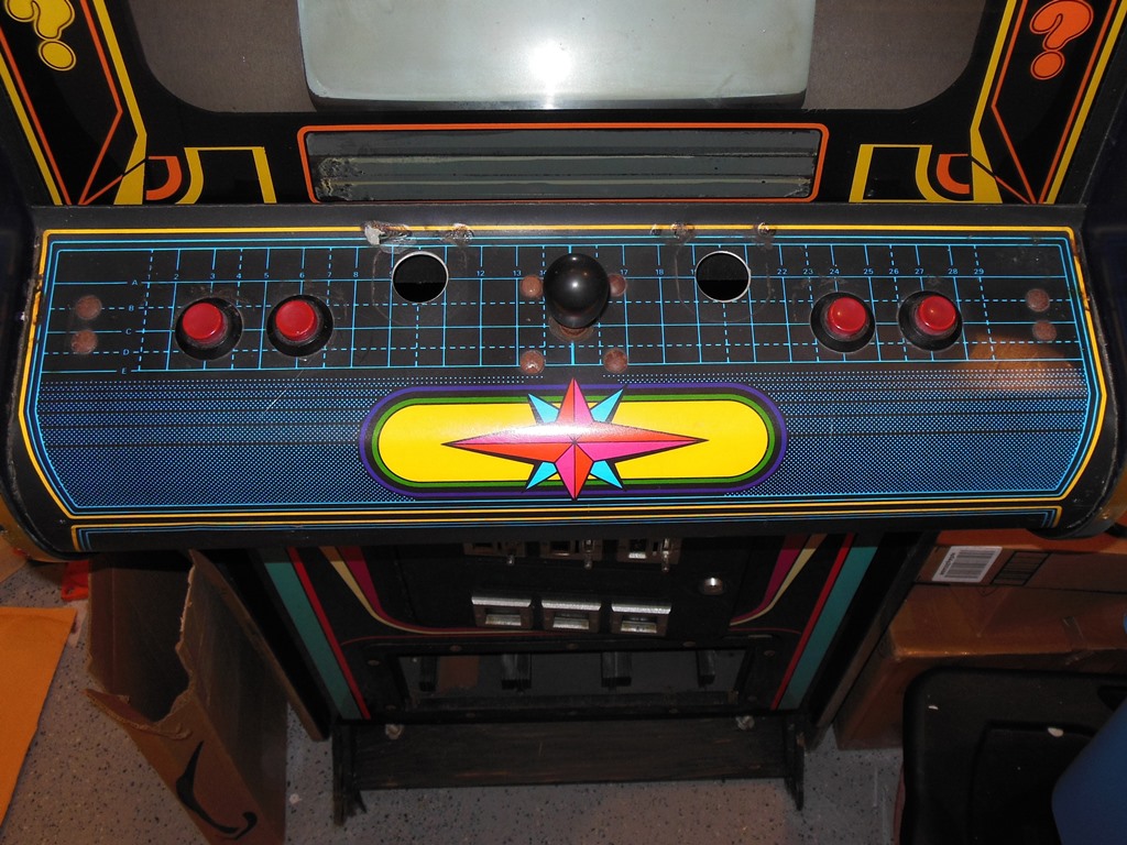
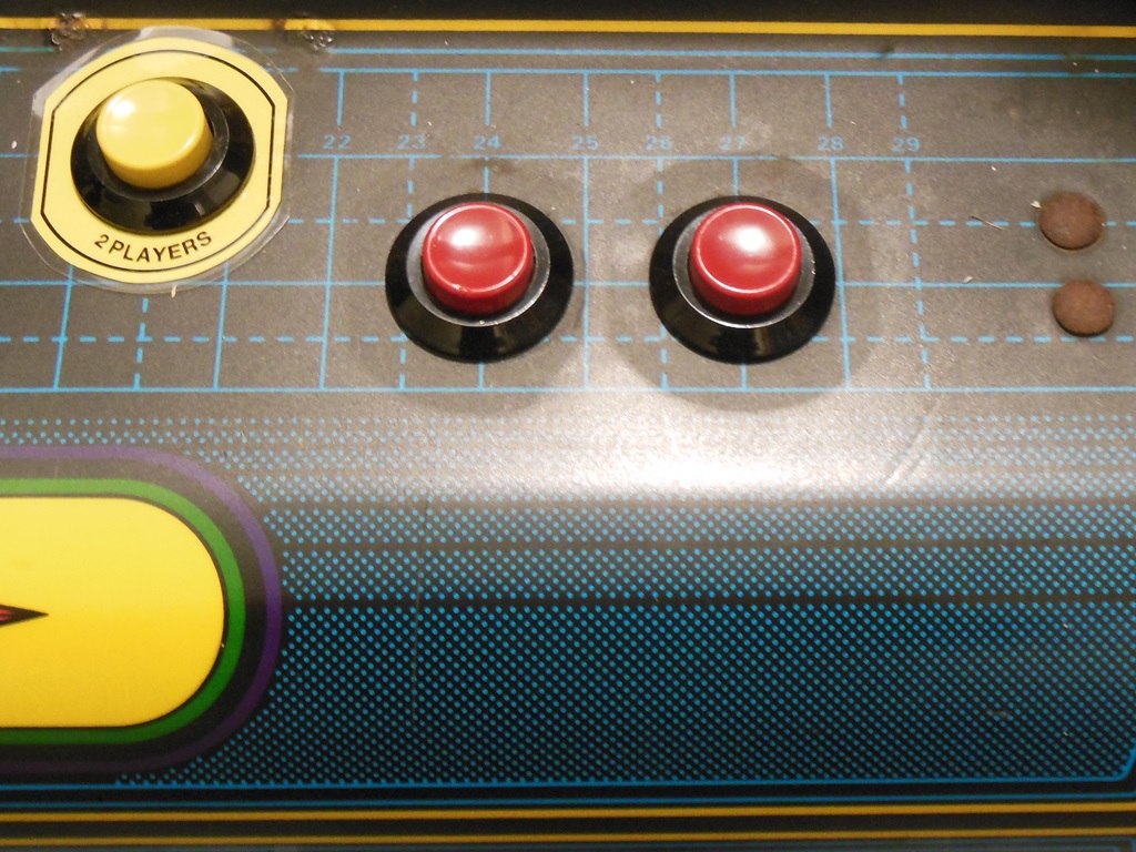
The control panel overlay was in good condition but the button collars were missing on the fire buttons and the player 2 collar was mostly peeled away. The player 1 collar was still intact, thankfully, to use as a reference to make replacements for the others.
|
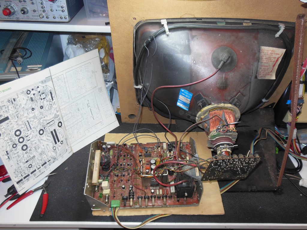
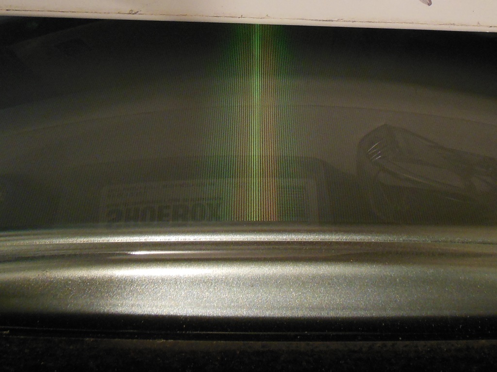
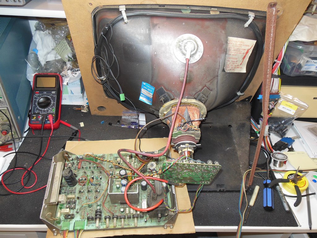
I had a couple of Hantarex MTC-900E chassis to try out as a replacement for the missing chassis. The first one tried had horizontal collapse, a rare failure mode since the horizontal drive is part of the HV generation circuit so it's not usually possible for it to be missing with HV still present. The first step was to cap kit the chassis. Post cap kit the picture quality was improved but still collapsed :(

|
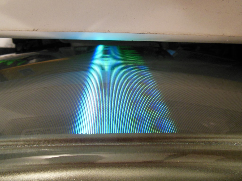
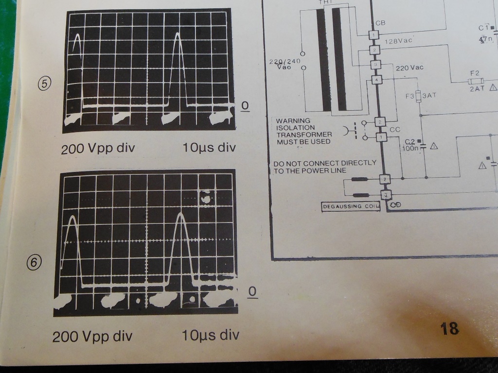
Measuring waveform 6 from the manual confirmed that the LOPT input that was supposed to be an ~800V peak signal was only ~600V peak. The peak itself was also wider than shown in the manual. I'd already confirmed that the B+ and horizontal drive output looked good. The yoke on my test CRT is known good so that left only the LOPT itself as the problem. Since I had no spare LOPT's in stock to replace it I set this chassis aside.
|
The second Hantarex MTC-900E chassis had some physical damage. Initial testing indicated it was running but the vertical sync wouldn't lock, a capacitor on the neck board vented out and the picture quality was poor. A cap kit took care of the vented capacitor on the neck board but still left no vertical sync and now the red gun was full on. The full on red was a simple dry joint on a drive transistor on the neck board.
Investigating the lack of vertical sync found no output from pin 8 of IC2 (TDA2593), the vertical sync IC. Replacing the TDA2593 had no effect :( Further, during triage the green gun stuck full on. Going after the green issue, no output was detected on TR22 (BC237) though changing it didn't fix the problem. Thankfully for this kind of issue a compare and contrast between the defective gun and the working ones really helps find single gun issues. In this case the output from TR29 seemed bad and replacing TR29 fixed the green drive. On return to the sync issue I was able to find a spot on the sync pot where the sync would lock reliably.
The next problem to work on was that the RGB balance was very poor. All three colours looked very different on the scope suggesting multiple issues across them. These issues came down to various small signal transistors in the colour pre-amp section (a common problem on this chassis). TR8 & TR26 were bad along with various other BC237/BC307 and R127 on the neck board was split in two. With all of that taken care of, the colour balance looked good.
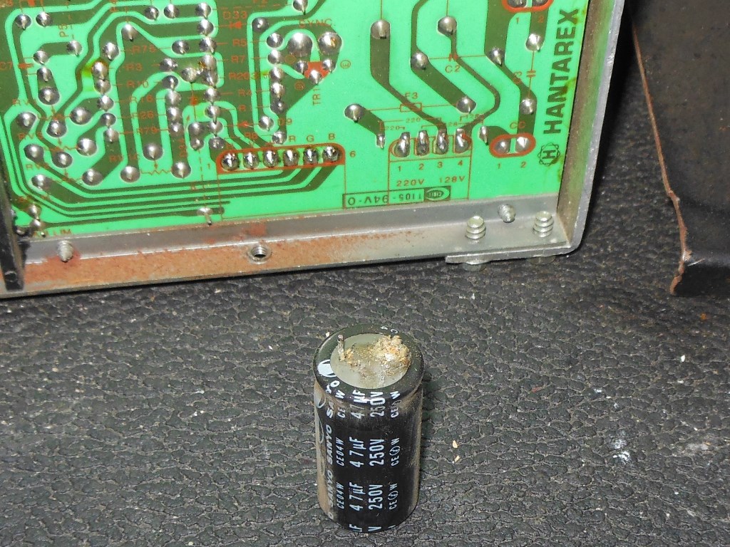
Next up was to address the picture being two small and with noticeable ripple across it. B+ measured 102-105V, both too low and seemingly unregulated. Investigating the power board found the 8.8V feed missing. TR7 was removed and tested bad. On replacement the 8.8V read 2.6V, getting better but still not right. Replacing both the BF871 and BF872 (both of which tested fine on my meter for Hfe but I suspected really were faulty) fixed the power supply, bringing back a full-size ripple-free picture.
|
After a few hours of burn in on the bench the chassis was fitted into the cab for further burn in testing. The chassis was installed without issue. Using a Konami Super Basketball test PCB for first power on yielded a workable over bright picture that otherwise looked good. The marque light was also working. After two hours in the cabinet the monitor showed green raster over the picture :(
Back on the bench, the green raster problem was intermittent. The signal input to the neck PCB looked OK but the base of TR29 looked jittery. This traced to TR20 that was replaced and fixed the green raster but revealed blue raster and poor red drive. The red signals looked off at TR11 and replacing it fixed the red. The blue signal still looked bad on TR21 & TR18. Replacing TR21 fixed the blue drive and the picture was back OK again.
|
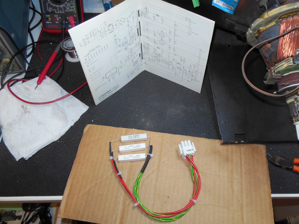
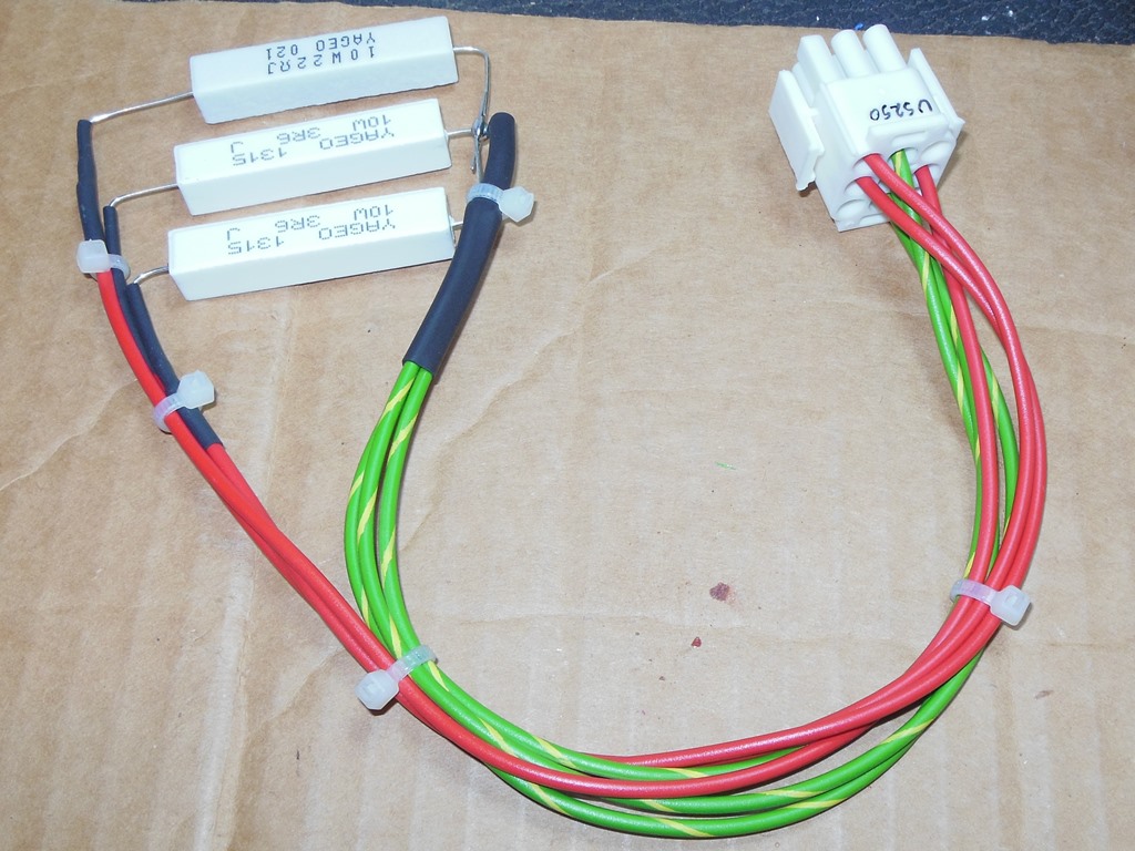
Since this was the first machine I'd encountered with a Hantarex US250 power supply I needed to build a dummy load to be able to test & fix it on the bench (it needs a load to work properly). The dummy load covered the +5V and +12V rails.
|
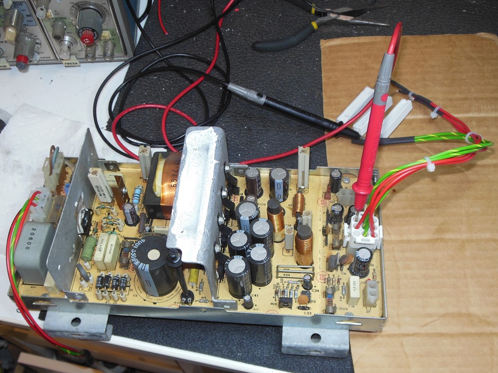
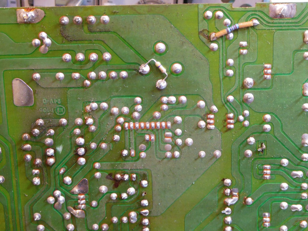
Testing the Hantarex US250 on the bench with the dummy load revealed that it was mostly working properly. The only problem seemed to be a missing -5V supply that was quickly isolated to a very obvious blown 7905 -5V regulator. Replacing the regulator fixed the -5V and the power supply was now fully working.
|
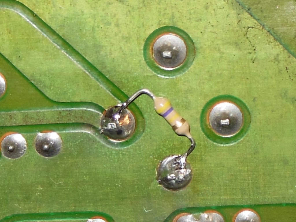
The Hantarex US250 is notorious for being hazardous to work on due to a large high voltage capacitor that holds significant charge making the power supply "live" long after it's switched off. For my own safety, I added a high value (470 KOhm) bleed resistor across the capacitor to "drain" the charge after power off to a safe level within a few minutes (down from 300V to 70V after 3 minutes of power off).

|
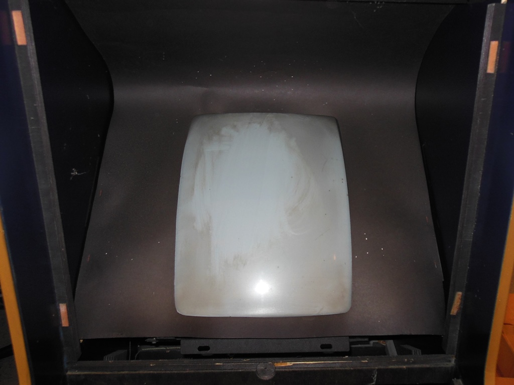
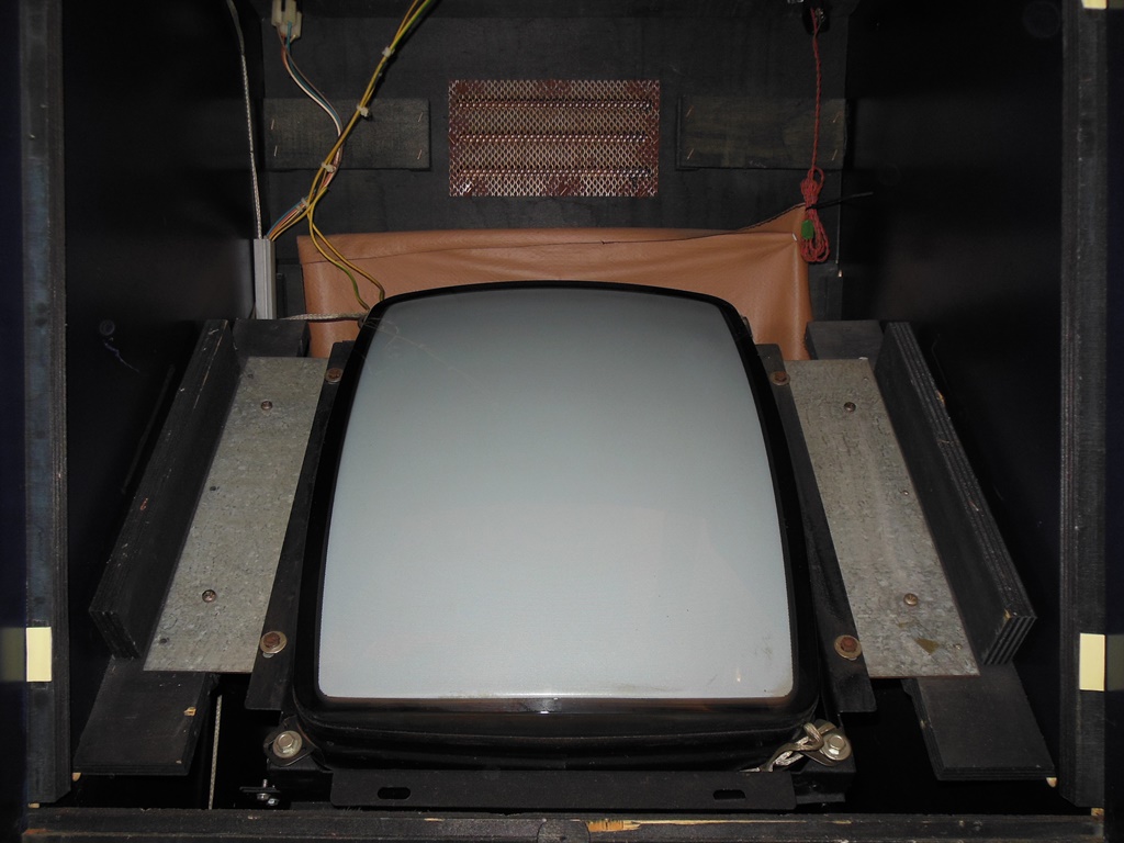
Clearing a little of the dirt from the CRT allowed some initial monitor setup (I deferred on a full setup of the picture until I had an Arian Mission running in it). I took the opportunity to clean the marque & marque light whilst the monitor glass was off.
|
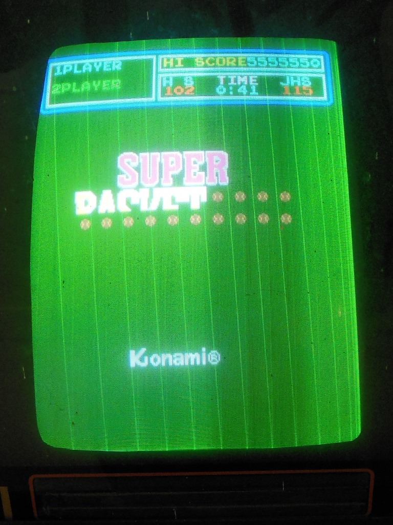
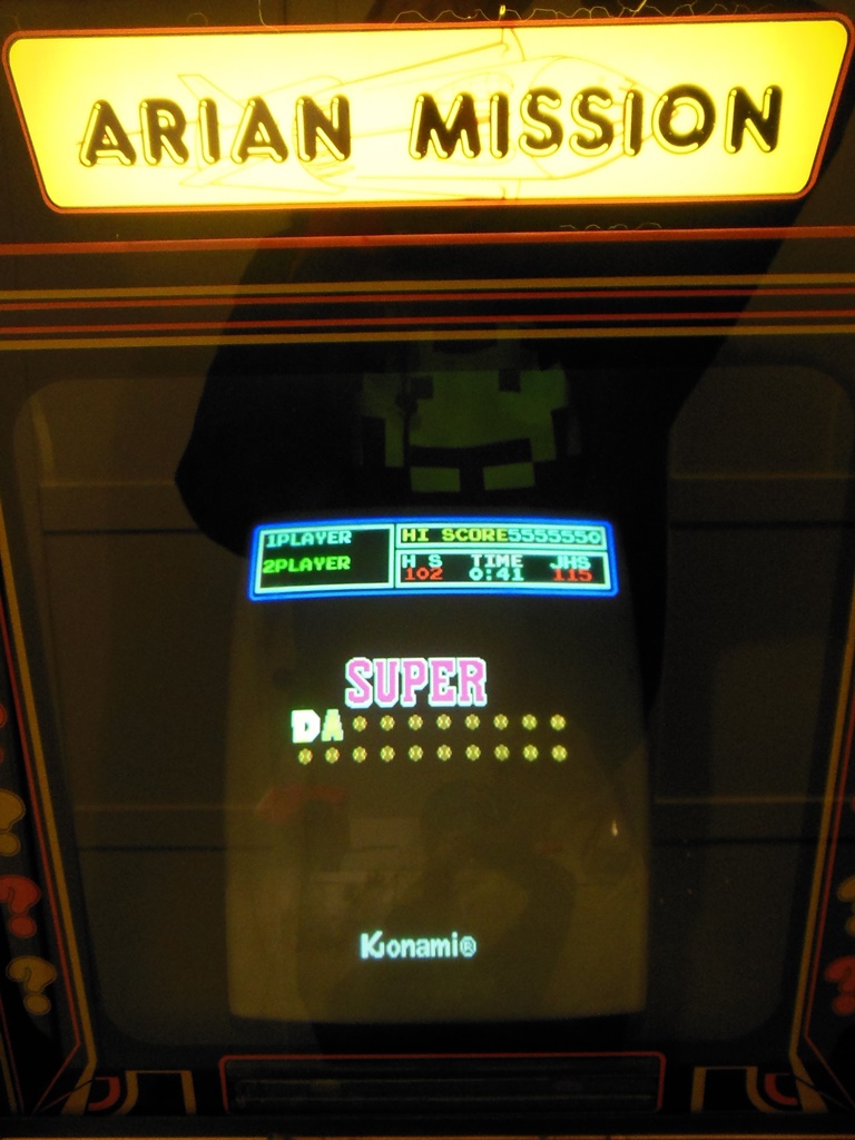
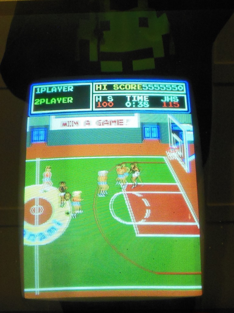
The monitor was adjusted to assess picture quality. With the Konami Super Basketball game PCB the adjusted pictured looked excellent (the second photo looks blurry because the court is scrolling).


|
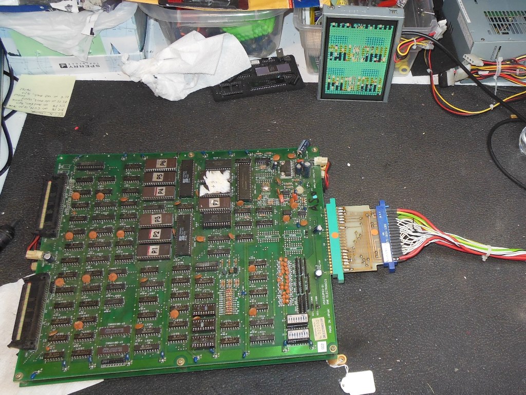
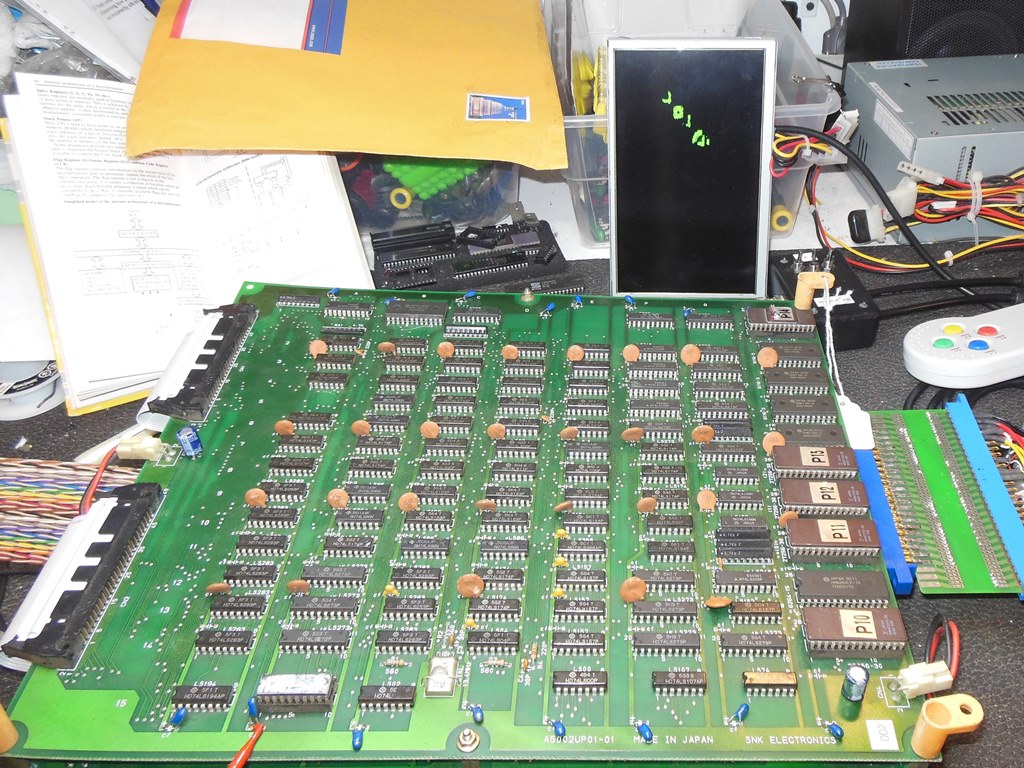
The SNK Arian Mission game PCB (also known under the title Alpha Mission and A.S.O.) seemed relatively rare to find. Luckily a collector in the UK had a couple of untested PCB's to start with. One was in better physical condition than the other but neither were working as is so repairs were needed. I selected the most promising candidate to start with. I also added support for Arian Mission to the Arduino ICT to aide with board repair.
|
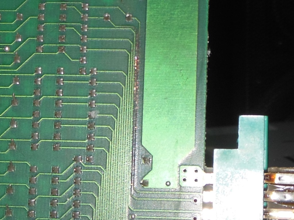
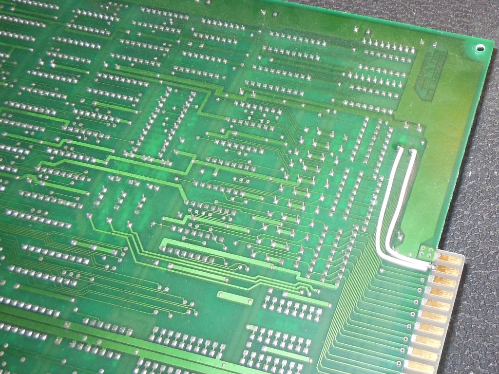
Initially the board would fail one of the self-tests or not boot at all. The first step was to replace the inter-board ribbon cables that looked rough. That improved things considerably, with the game coming up most of the time (still crashing/not booting sometimes). The game wouldn't coin up, an issue that was traced to burnt out tracks between the edge connector and the coin input circuit on the PCB. With the tracks repaired the game could be coined and played. There some odd pixel sparkles here and there but aside from that everything appeared to be working fine. The no boot issue I left for now since it cleared on power cycle.
|
Since this was a game I hadn't previously worked with, I made an SNK to JAMMA adaptor for it for the test bench. I could have kept using the original cabinet SNK to Konami adaptor with a Konami to JAMMA adaptor on the bench but the combination of adaptors was causing a lot of voltage drop on the power rails that I needed to eliminate as a potential cause for the intermittent boot issues I was still seeing on the game PCB. Alas, it wasn't and even with good healthy power rails the game PCB still had an intermittent boot problem :(
|
|
|
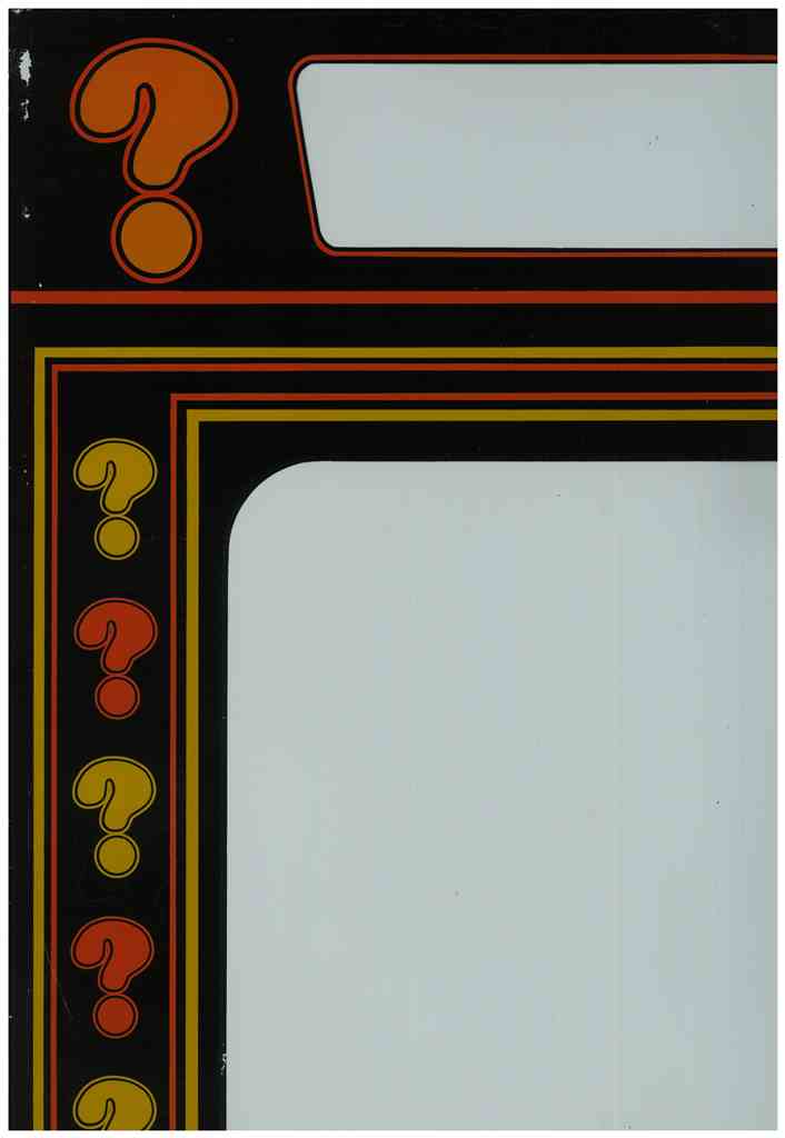
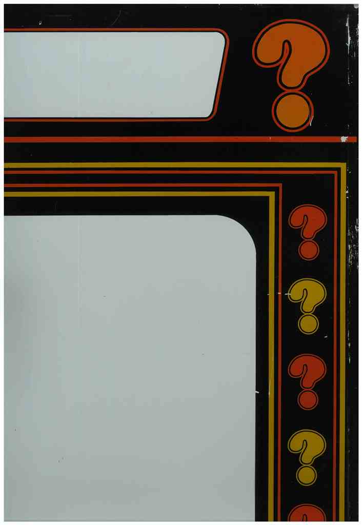
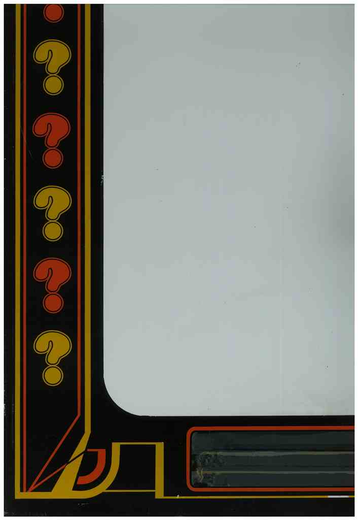
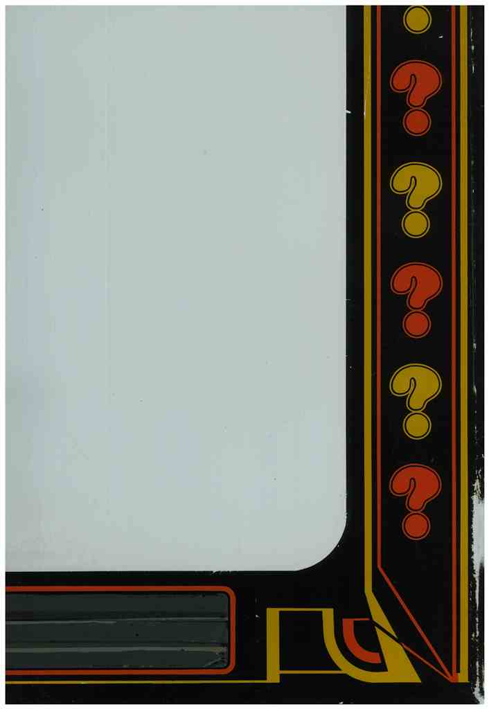
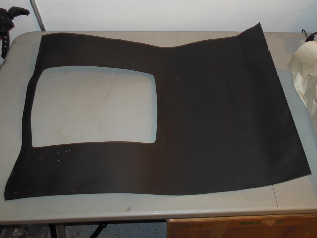
Scanned in the MVGS Neptune monitor glass & Arian Mission marque.
600 DPI MVGS Neptune monitor glass scan (22.9MB).
|
|
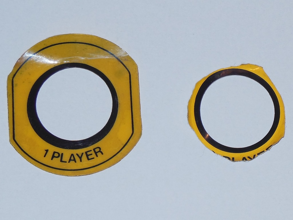
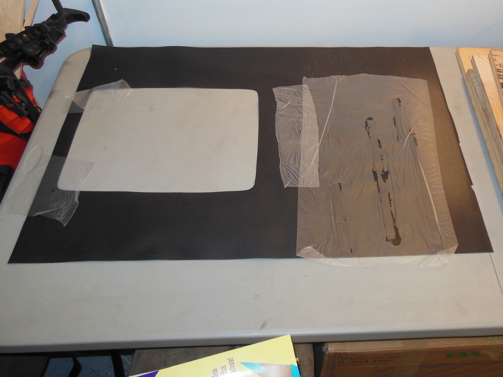
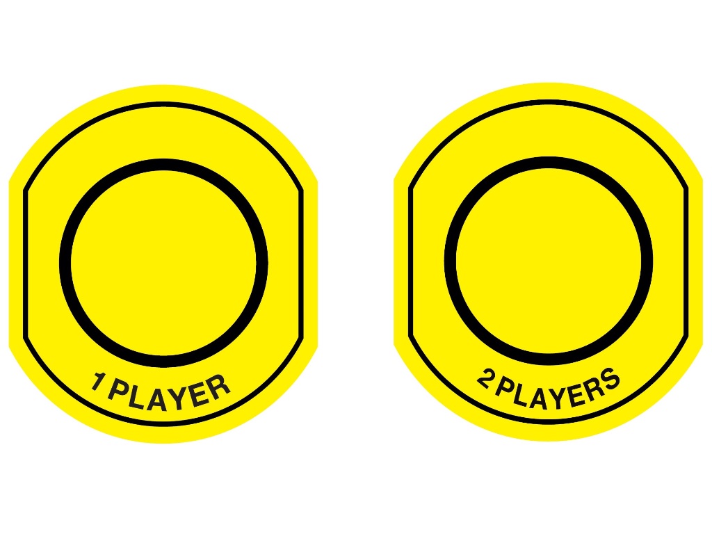
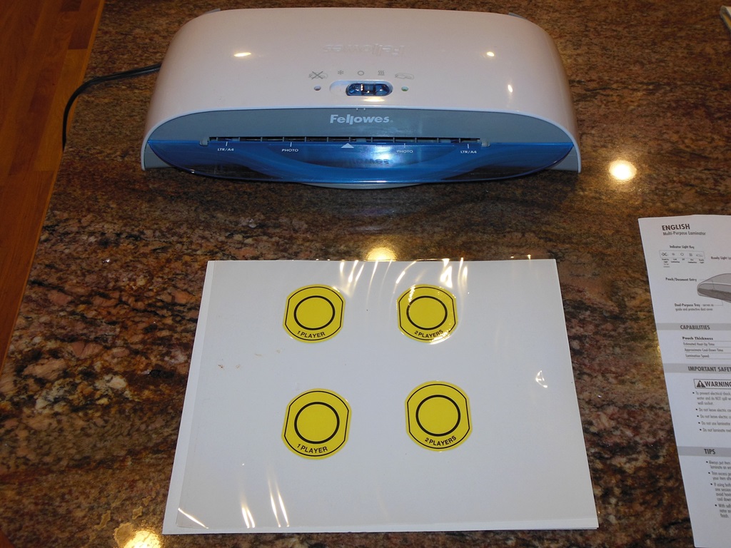
The start button collars were removed so they could be scanned as the basis for a reproduction of both.
600 DPI MVGS Neptune start button collar scan (269KB).
|
The control panel secures the bottom of the glass using a foam spacer that was partly rotted away. This was replaced with a new foam strip.

|
The surround was in pretty good condition and was removed for cleaning and flattening out to reform it. The CRT had very little nicotine, just dust & dirt, so cleaning it was straight forward.

|
The monitor surround was a little droopy with some odd creases. There were also some white paint splashes on it that I couldn't tell for sure if they were factory "stars" or just odd paint splashes so I left them as is.
|
After a wipe down with a damp cloth, flattening and the addition of reinforcements strips on the creases the surround looked good.
|
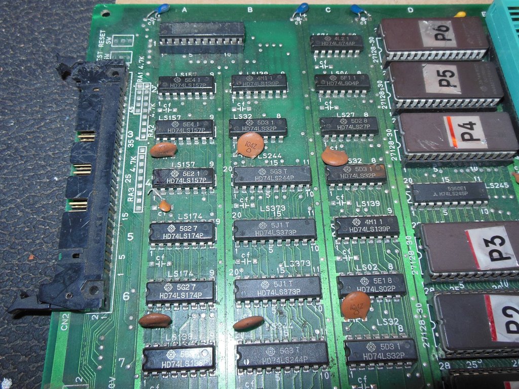
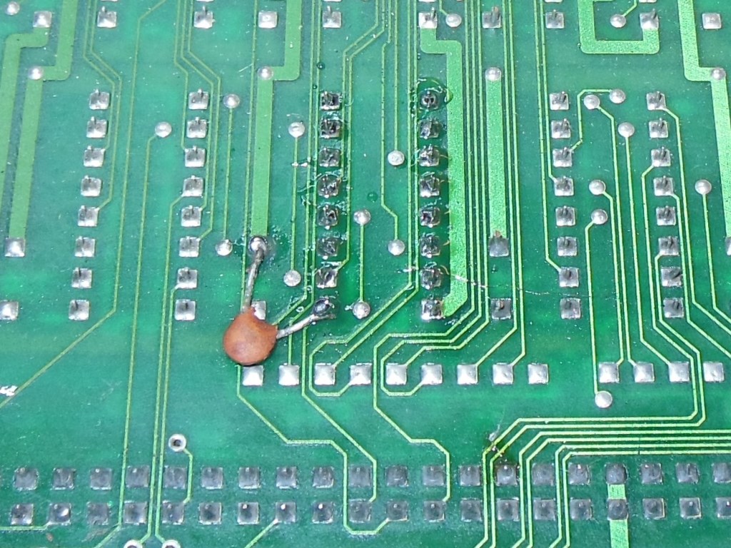
The game PCB was still having intermittent boot issues that were starting to lean towards no boot rather than boot. Though I had the game added to the Arduino ICT the problem was getting into a state where the no boot problem was more persistant. Finally the PCB ended up in a persistent no boot state that confirmed ROM Check OK but the RAM check failed. The basic RAM Write/Read test passed, returning 11,22,44,88 as expected so I suspected a RAM address problem. I extended the Arduino ICT options to include a RAM address test that would walk up the RAM addresses until it hit a bad address bit. Sure enough this caught a RAM address bit error with a bad address bit 6. Tracing through with a scope found bad signals on video IC A4 (LS157) pin 7 and video IC A3 (LS157) pins 9 & 12. Changing video A4 (and moving the kludge capacitor upon it to the back of the PCB out of the way) brought the game back to life.
The game ran OK for a short while then went back to reporting errors on CPU B. Inserting the Arduino ICT again showed RAM Check OK but all the RAM was bad. The address pin check flagged intermittent address pin errors for 00040,00080,0100,0200 across all RAM banks. Video IC A4 (LS157) pin 7 was back to looking bad again. This suggested a bad input pulling on pin 7. Sometimes it's possible to discover a problem with a resistance check. Poking around found video A6 pin 4 at 2.2 Ohms to ground and video A7 pin 10 at 28.4 Ohms to ground. On the CPU boards IC A3 pin 9 showed 28 Ohms to video IC A4 pin 7 that cleared when the ribbon cable was unplugged confirming a problem on the video PCB. Going over the PCB did not find any common device that shares both signals - the only remaining cause I could think of was a track to track short. There were a couple of spots where the tracks ran parallel. The first spot didn't show anything with the meter but probing the second spot near the edge connector suddenly caused the resistance to jump to 125 Ohms. There appeared to be some residue near the underside of the edge connector that I cleaned off with flux cleaner. This eliminated all the odd resistances and the game was back working OK with no further boot issues :)
There was still a minor issues with odd pixel sparkles on a few background sprites that I left as is - without a set of schematics and the weak nature of the fault made it not worth pursuing to find at the present time (I had been using a bad scan of Marvin s Maze as a reference for an idea of the game hardware up to now).
|
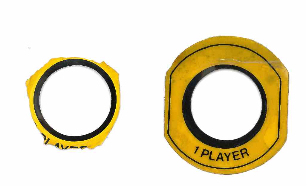
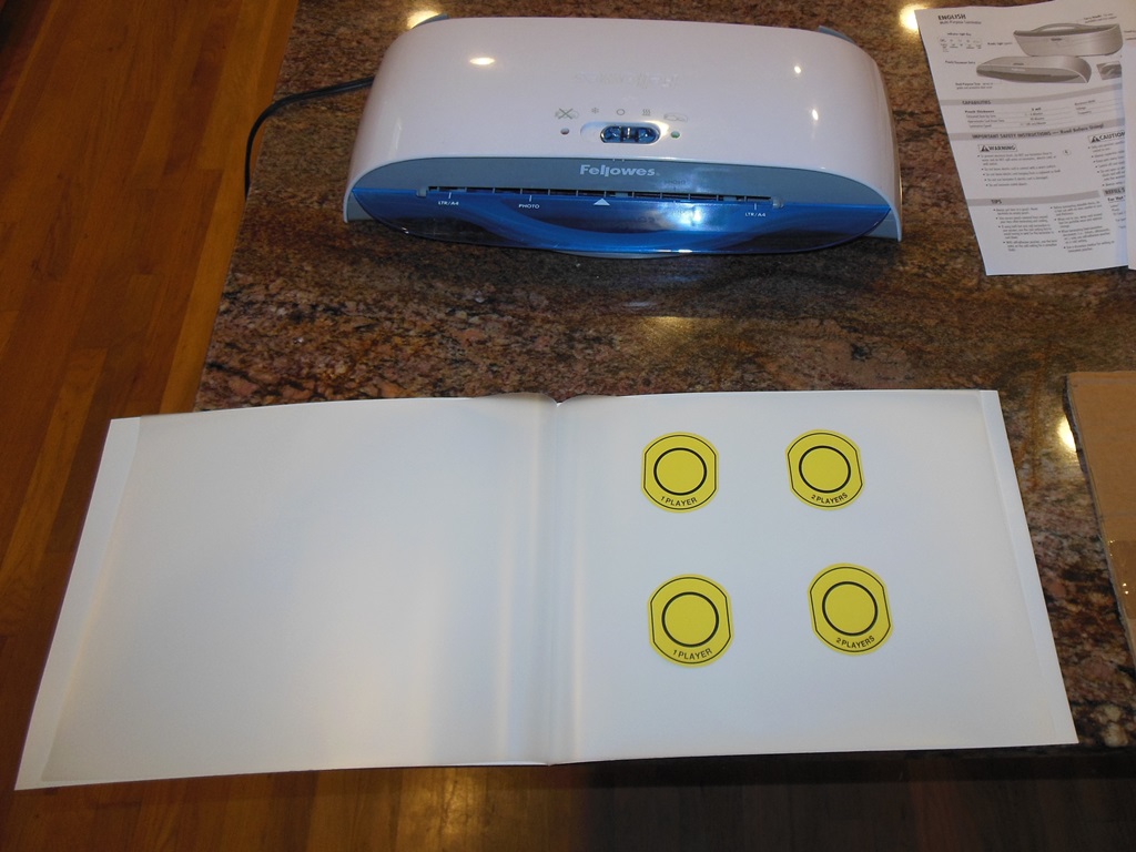
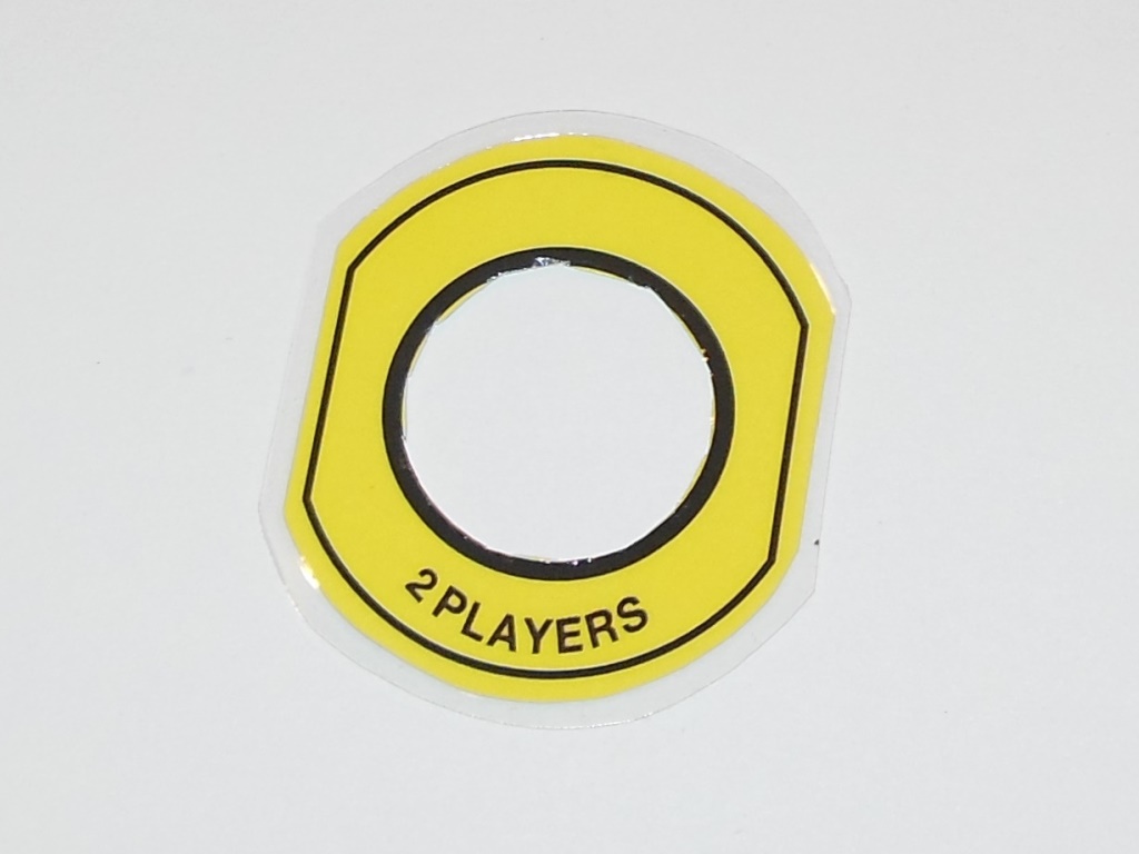
Etienne on the Dragons Lair Fans forum was able to re-create the player start button collar artwork.
Reproduction MVGS Neptune player 1 & 2 button collar artwork PDF (96KB).
|
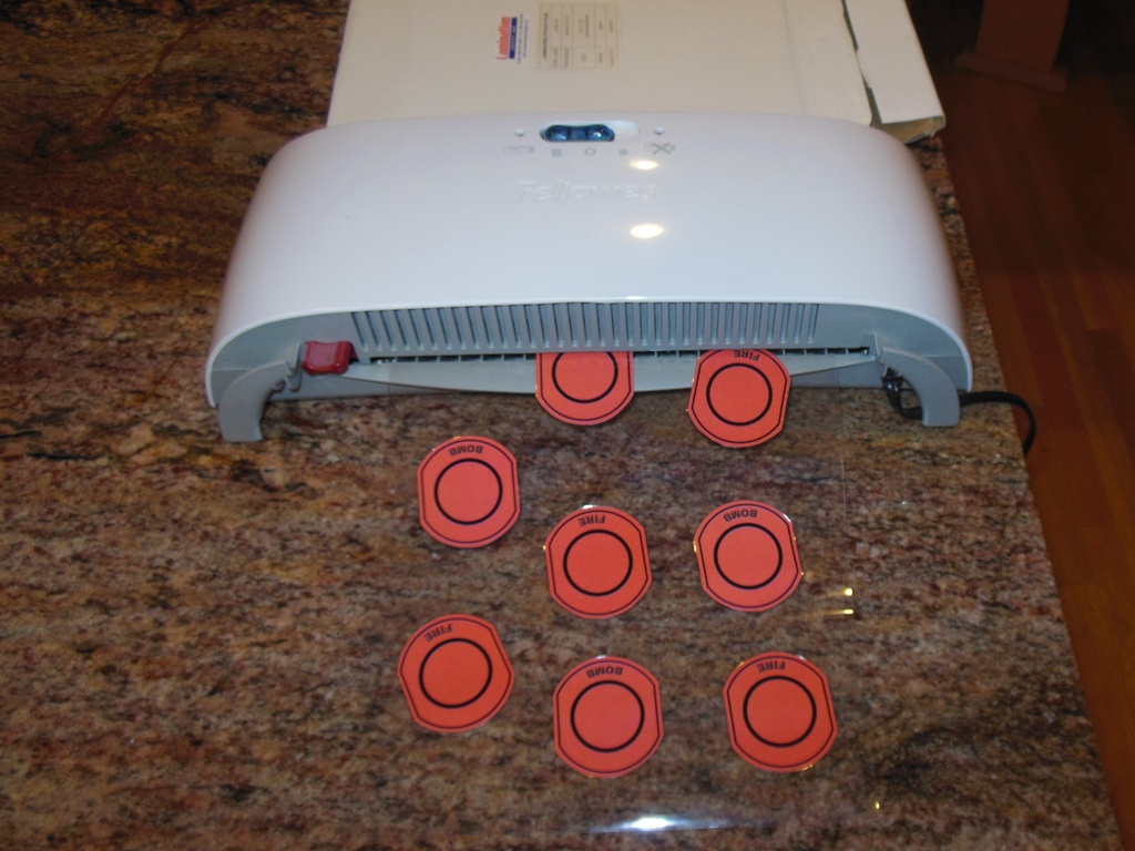
The repro was simple - colour laser print, laminate and cut out with craft knife. The original was a stick-on plastic overlay but this was close enough for me.
|
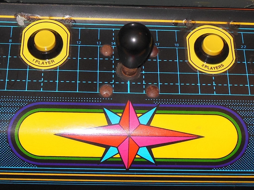
The repro collars fit perfectly on the panel and looked good. The originals were not quite as glossy as the laminated repro but it was good enough for now.
|
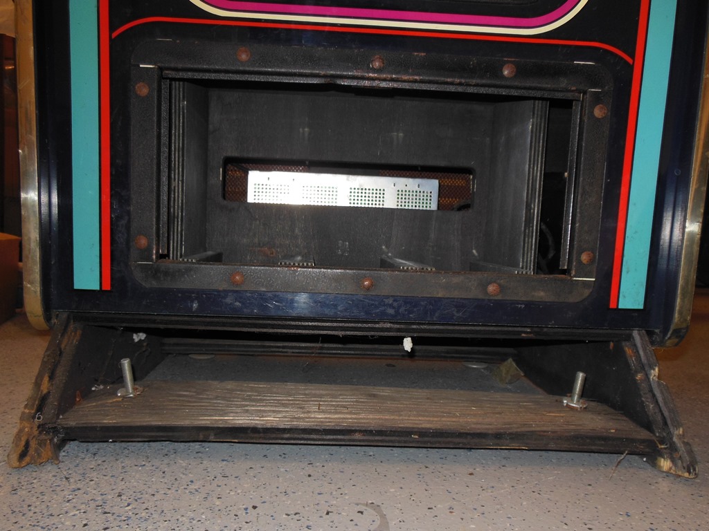
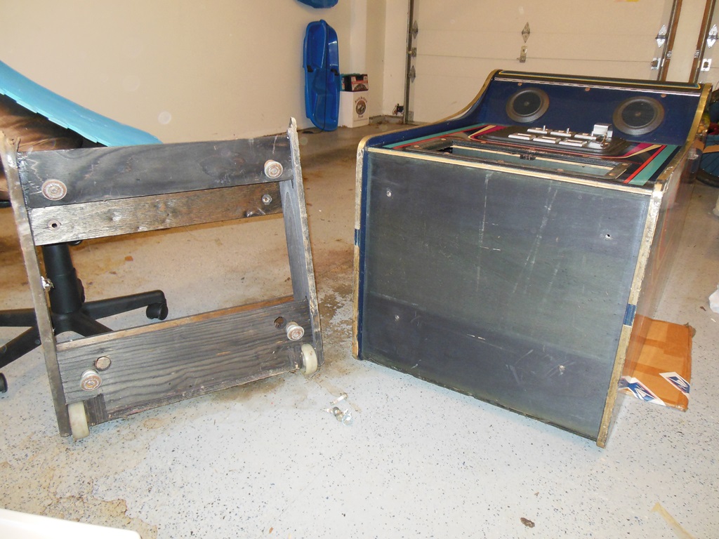
The original foot rest base was in poor condition. The foot rest itself (not shown) was swollen and falling apart. The base cross bar was split, the two sides swollen and crumbling. From the underside it was clear that one side of the base had been replaced at some point (one side was MDF and the other plywood). I decided to remove the foot rest base entirely and fit casters as usual.
|
The coin counter had been moved from behind the coin door to behind the cash box and the wiring hacked to reach it. I "undid" this hack to put the counter back to its factory location and tidied up the wiring.
|
On first assembly with the Arian Mission PCB the first problem was that the game PCB had bad graphics in cab. Investigation revealed that the +5V power rail was only 4.6V at the game PCB, even with the Hantarex US250 +5V pot turned up all the way. Poking around with a multi-meter found that a large portion of the voltage drop was through the SNK to Konami adaptor (the Konami standard does not allocate many pins for power, a known design limitation). Closer examination suggested that the actual track on the adaptor was the source of most of the drop. Fitting an additional thicker power wire in parallel with the adaptor track eliminated a chunk of drop that allowed the +5V to enter the PCB at 5.05V. The game ran fine after the modification with improved graphics.
|
Mostly assembled and setup the game was running fine and played well.
|
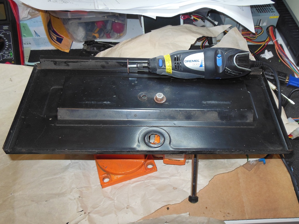
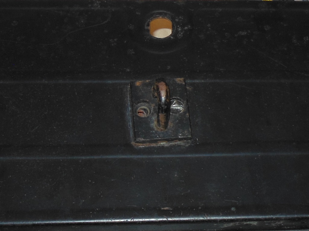
The cash box door was missing but I had a spare on a wrecked Money Money cab I was able to reuse. It had lock bar clasp drilled into it that needed a Dremel to remove the seized nut. The holes I simply covered with a piece of black duct tape.
|
Fully assembled, cleaned up and prepped for show.
|
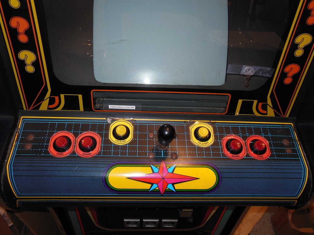
It was whilst I was cleaning the control panel that I noticed "shadows" around the fire buttons, left over residue from button collars. No part of them remained except for the residue, but it was clear they must have existed originally.
|
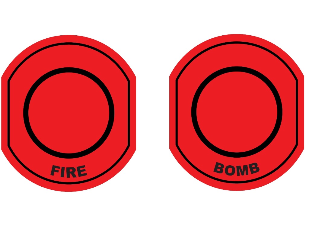
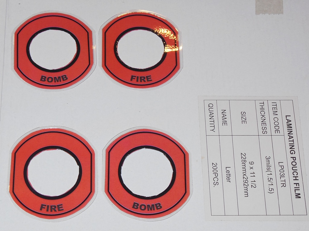
Another request for reproduction artwork for these buttons was answered by Ramakers on the Dragons Lair Fans forum who was able to re-create a couple of red "FIRE" and "BOMB" collar images (since the yellow start buttons had yellow collars we theorized that the fire button collars would have been red to match the buttons also).
Reproduction MVGS Neptune fire & bomb button collar artwork PDF (37KB).
|
The prints of the repro collars were laminated, cut out and fitted to control panel as before, completing the restore and the game was ready for the show.