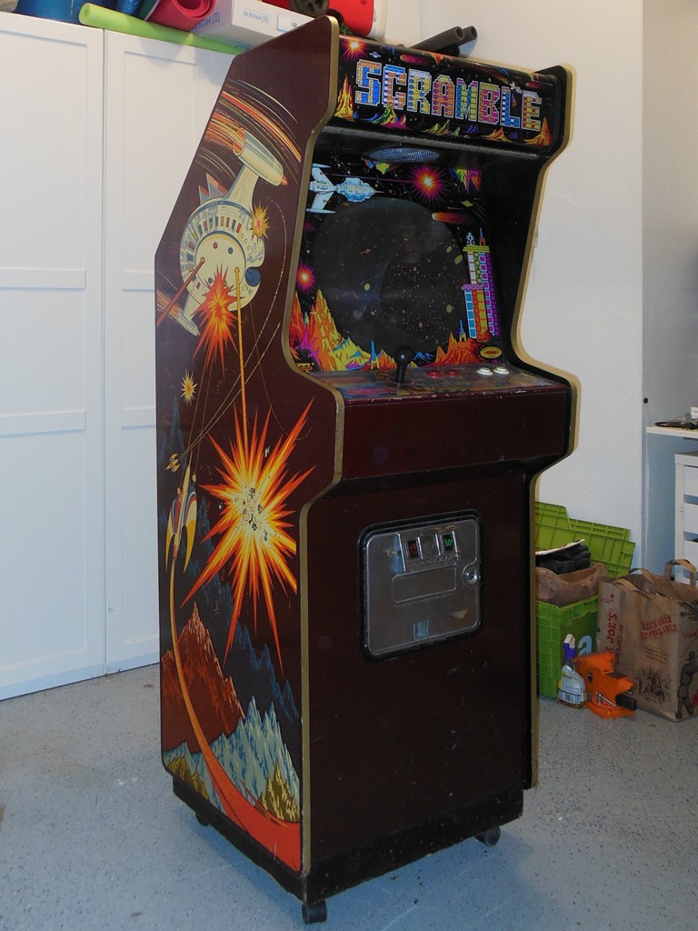
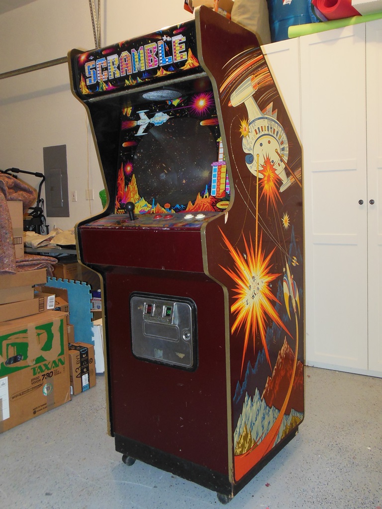
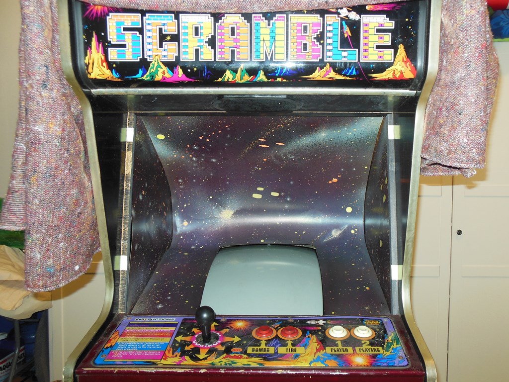
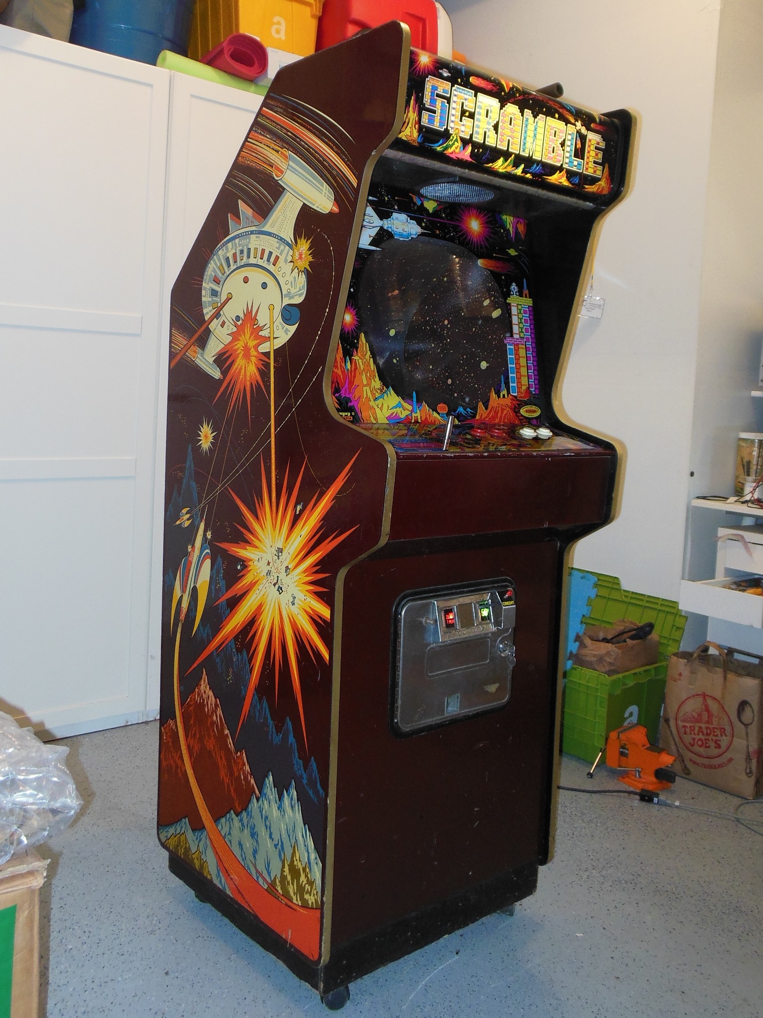
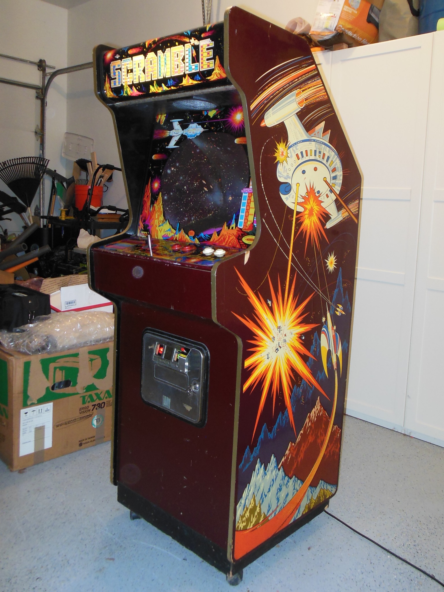
This game was acquired in the UK and came over to the US as part of "The Big Move". Given that it already had castors and a joystick "upgrade" I suspect it may have come from another collector or home rather than directly from an operator or operators warehouse.
|
|
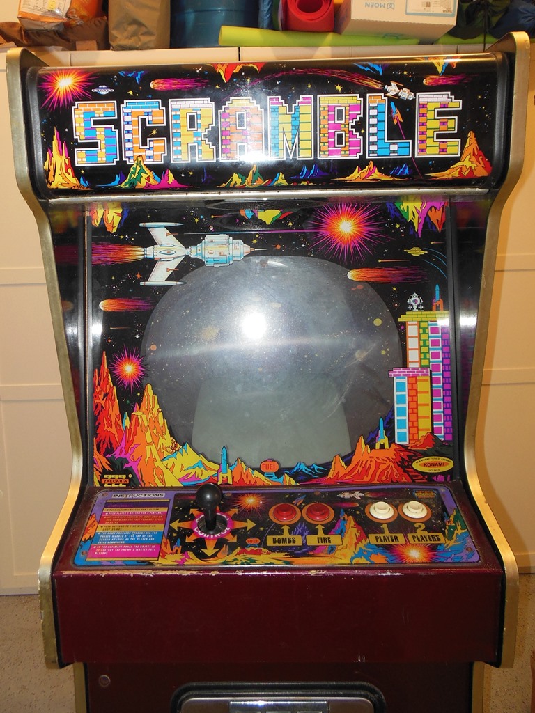
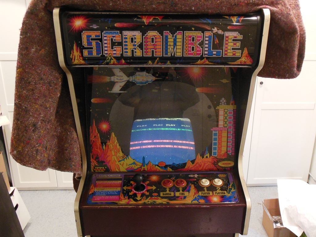
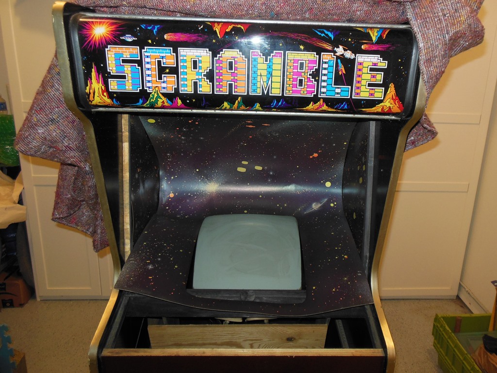
The exterior condition was pretty good - no major damage or missing pieces. The joystick had been replaced at some point and the joystick hole widened out that alas included drilling out the overlay :( Someone probably didn't like the chrome shaft joystick.
|
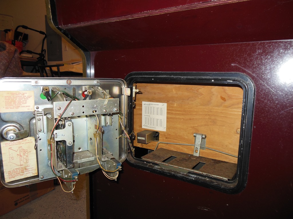
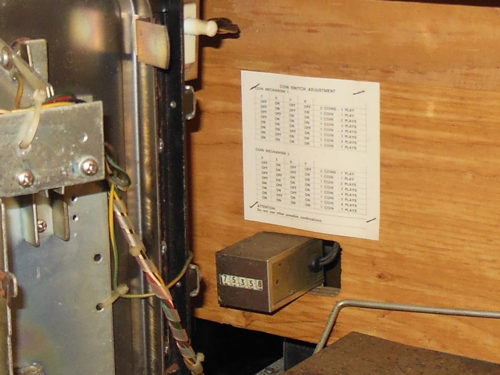
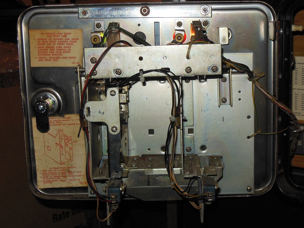
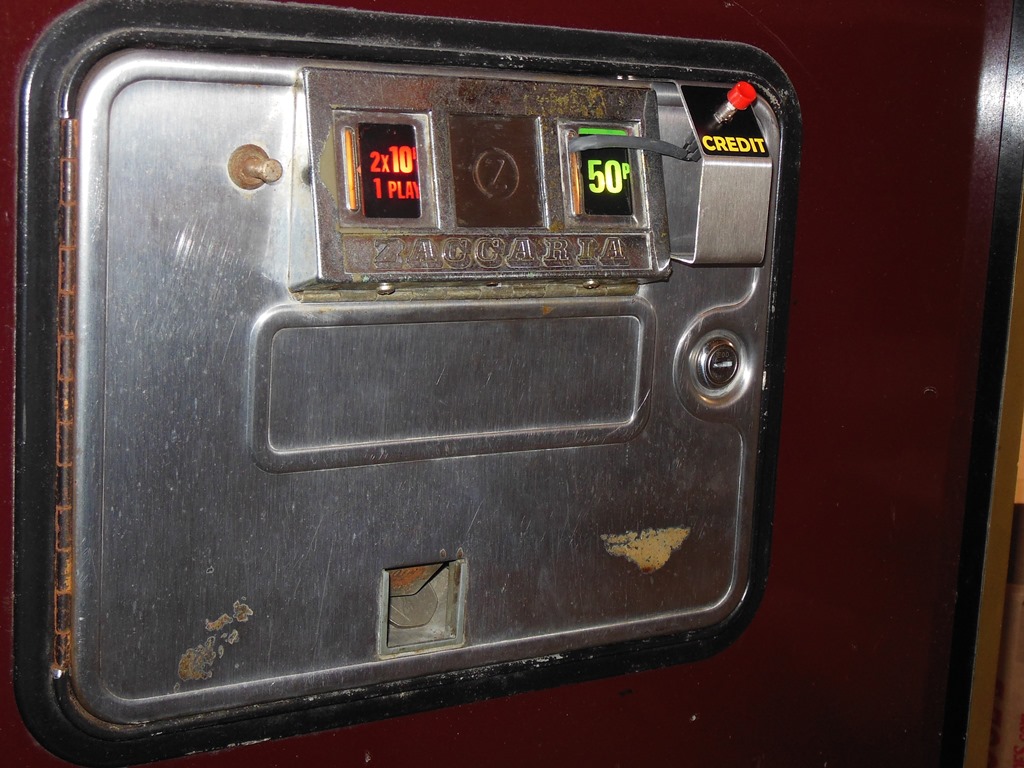
The coin door and wiring all looked complete and intact aside from the missing coin acceptors. The coin counter recorded 75,358 likely 10p drops.
|
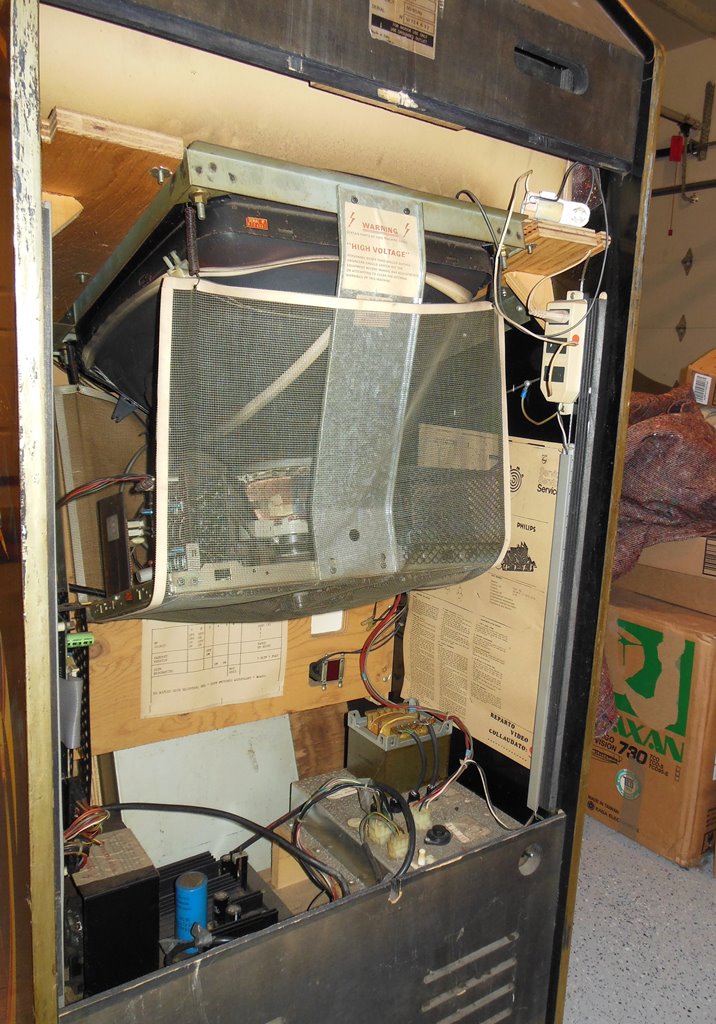
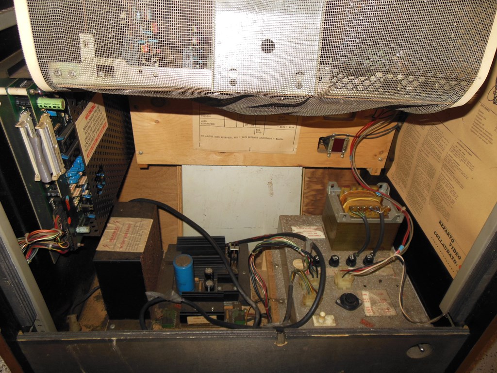
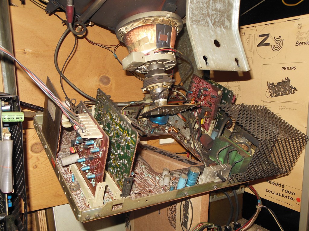
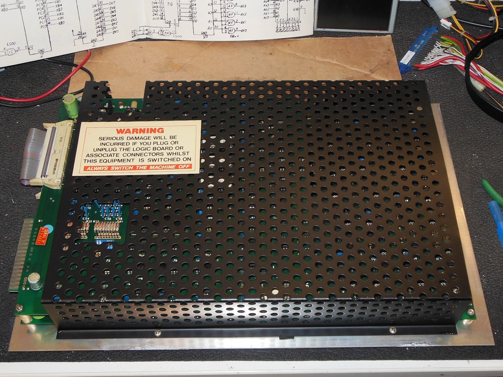
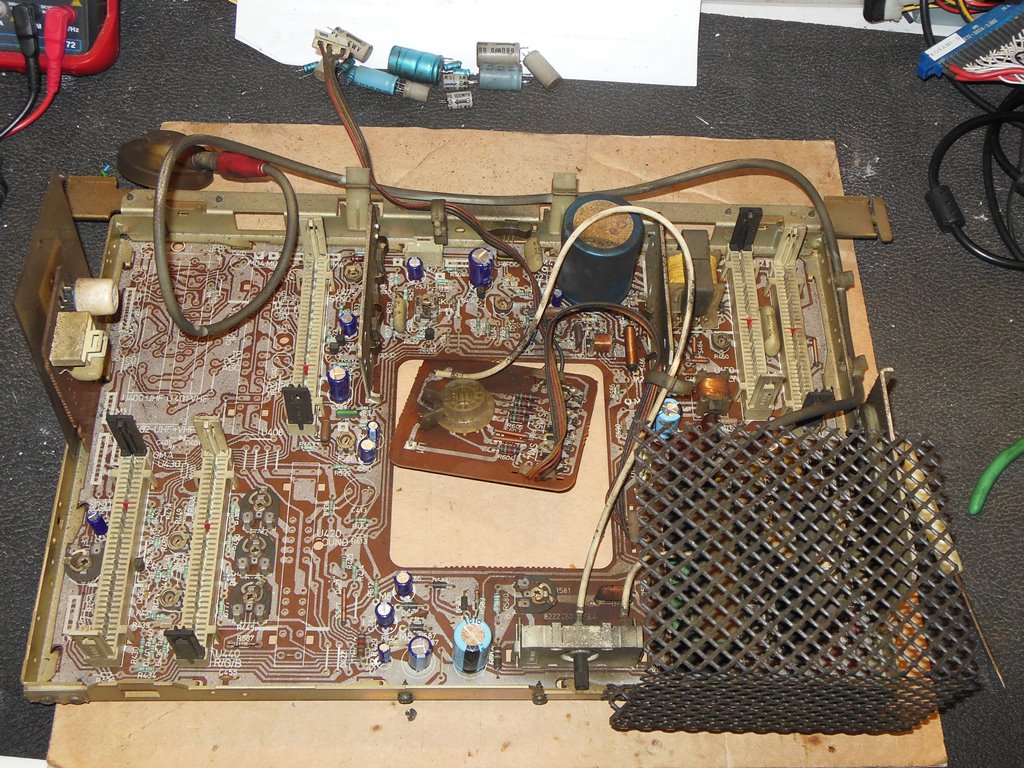
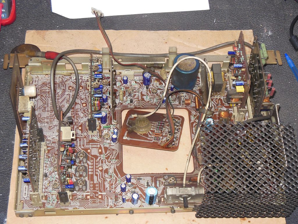
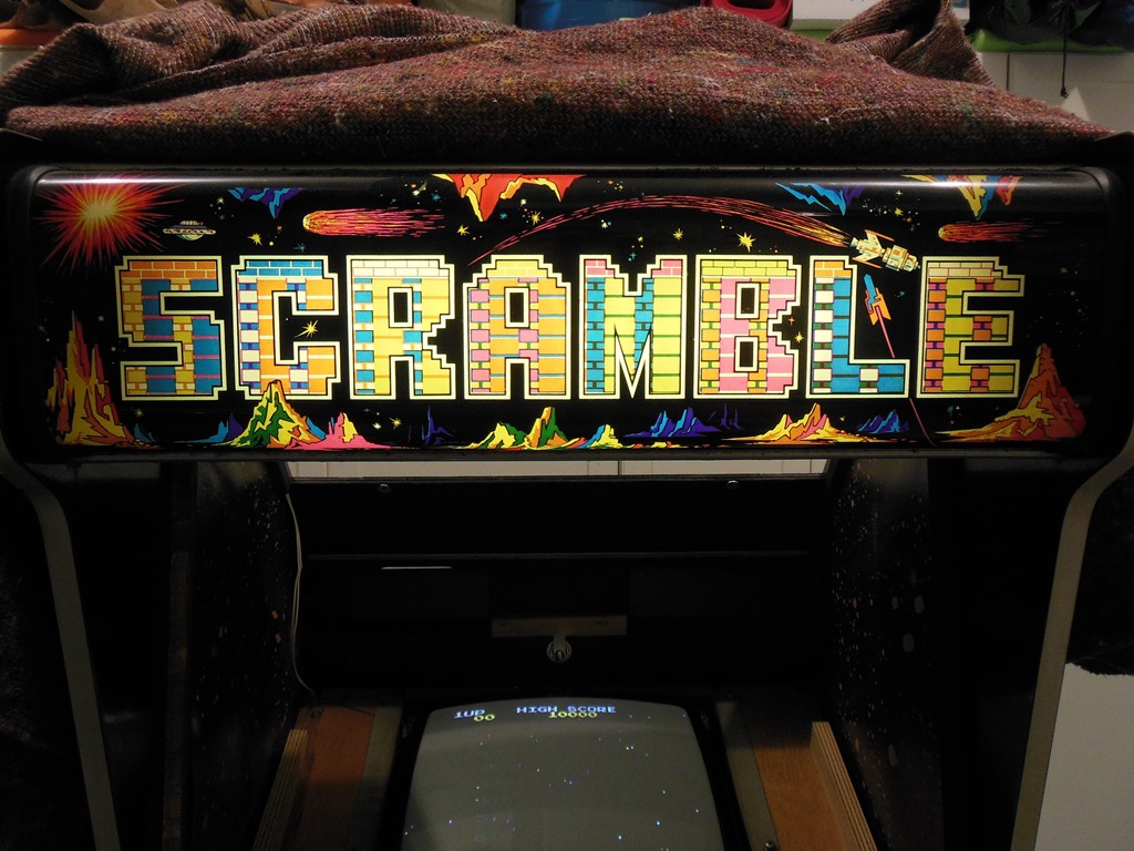
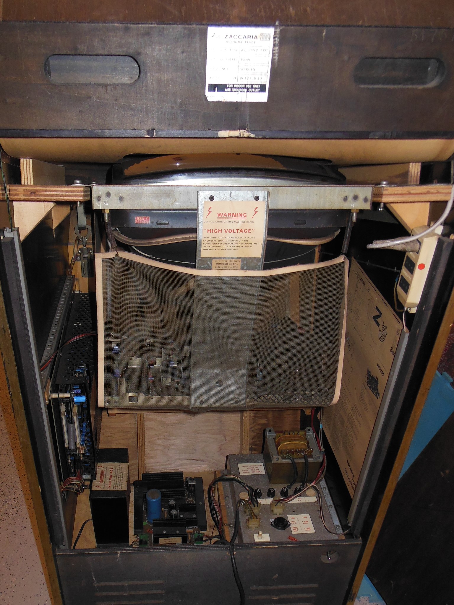
The internals of the game looked complete and all original. Even the monitor protective net and PCB cage were still present.

|
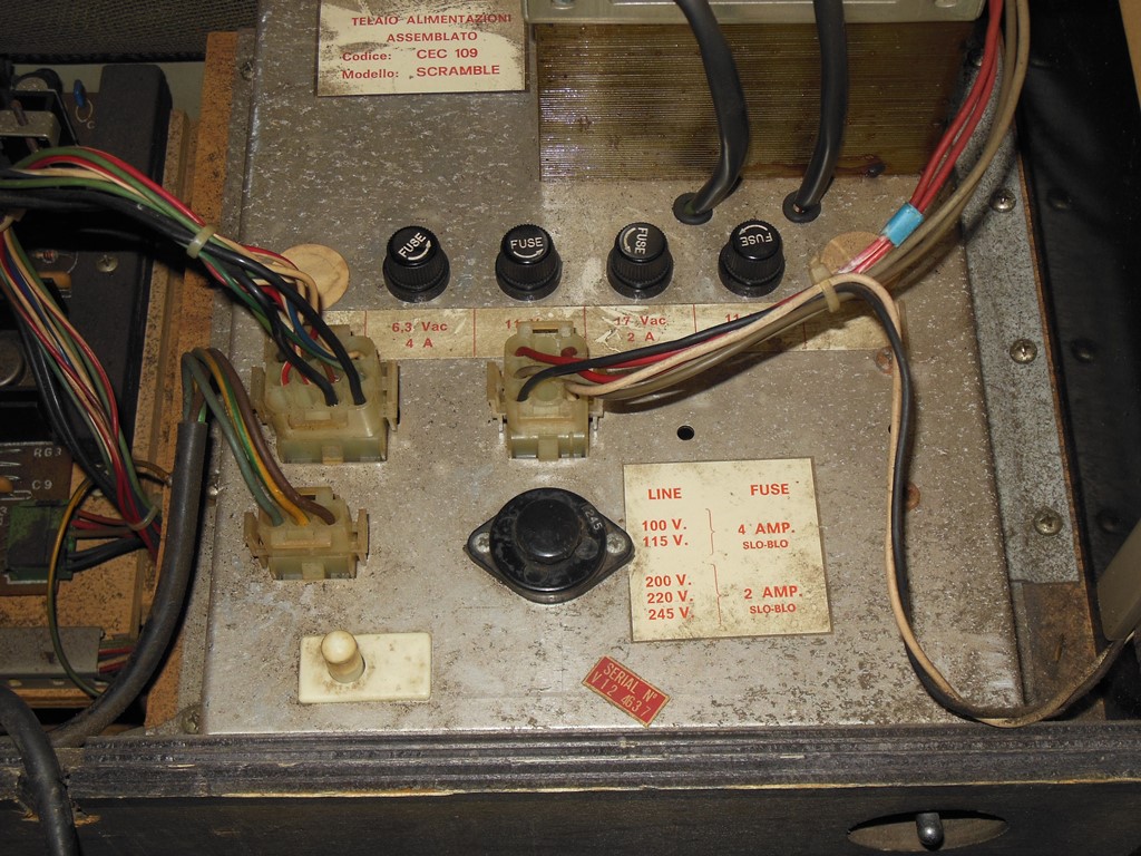
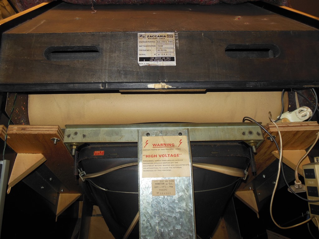
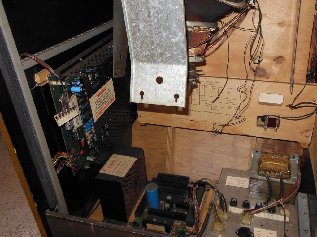
The power plinth and fan were dirty but looked complete otherwise. The PCB cage obscured the view of the PCB, but it looked clean. Towards the top, one socket of the marque light was dangling into the back of the cabinet so repair work was needed on the light assembly.

|
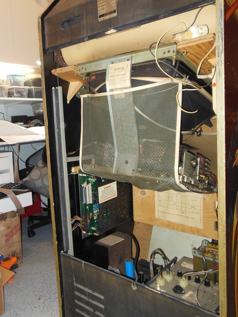
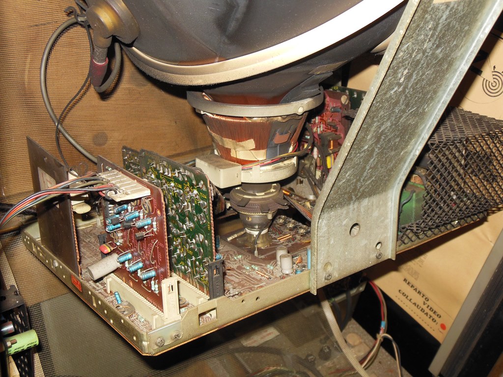
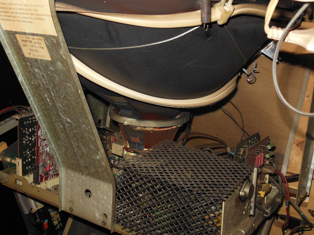
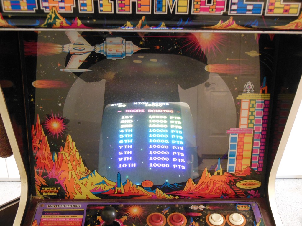
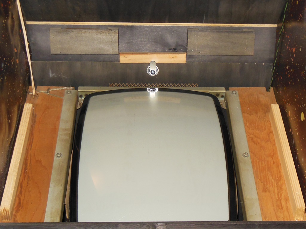
With the net removed the Philips KT-3 monitor looked complete and original.

|
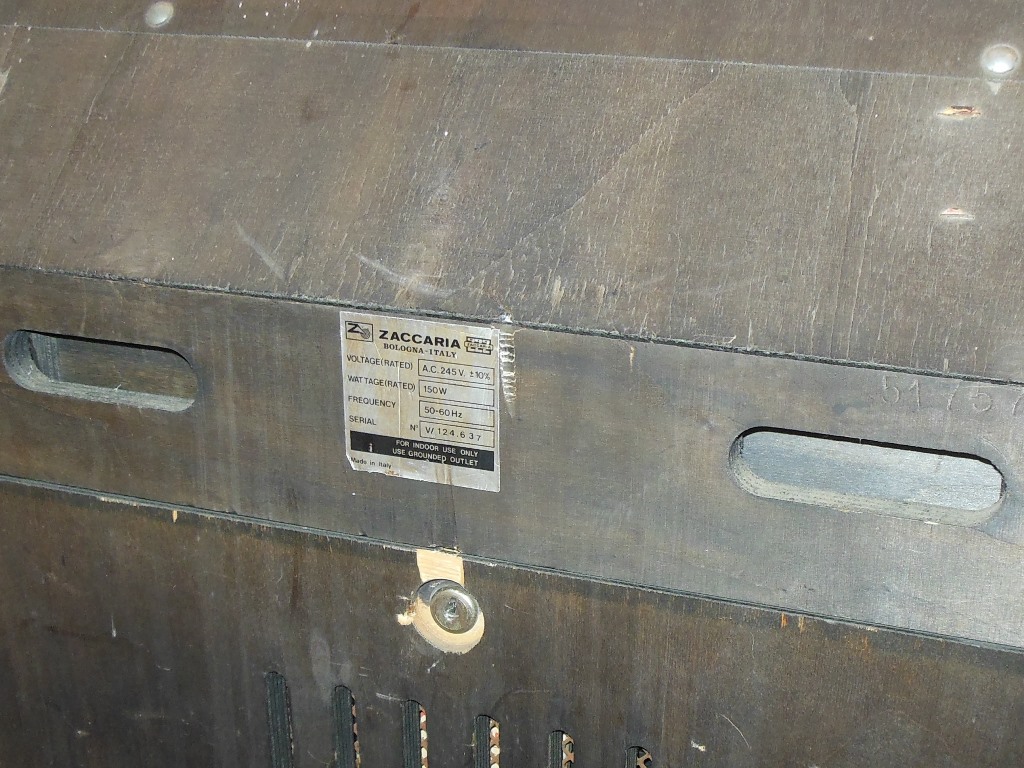
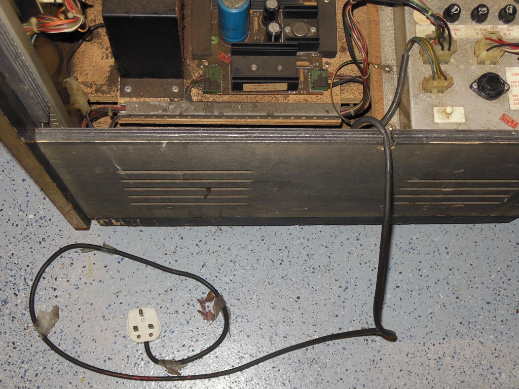
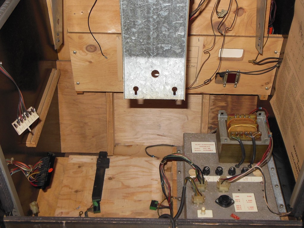
The UK plug was attached to a somewhat shorter than usual power cord. I thought about replacing the whole power cord but in the end decided that it was just long enough to live with. The power brick was set to 245V and the UK plug replaced with the usual IE-C14 style I'd been using to keep 240V based games separate from US 120V.
|
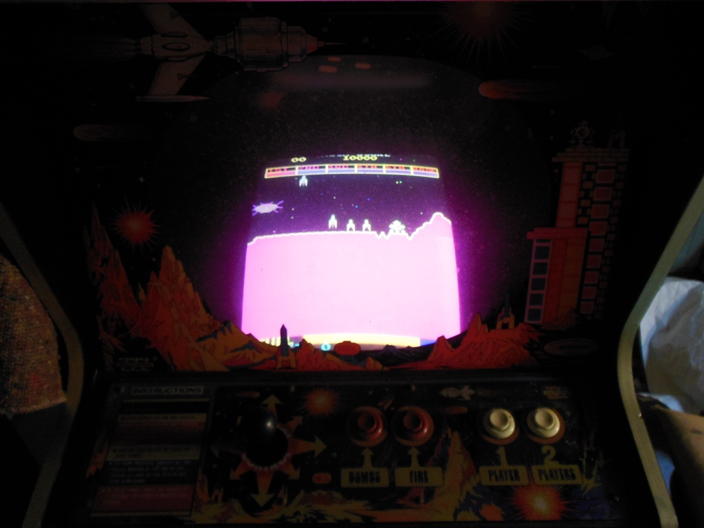
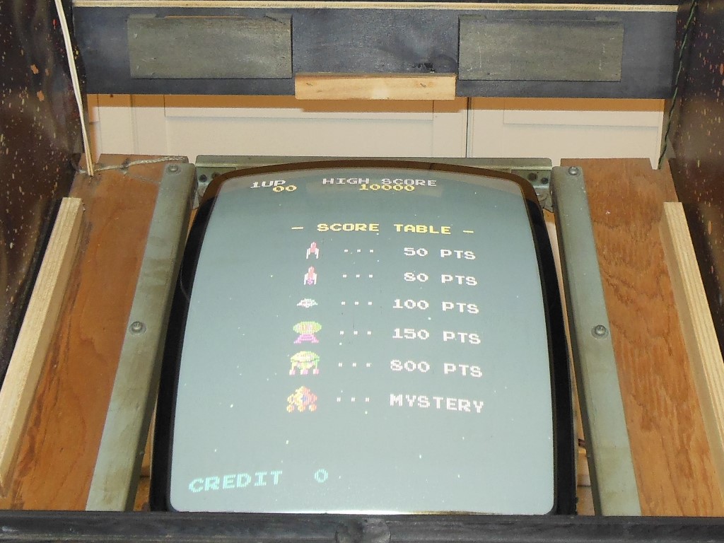
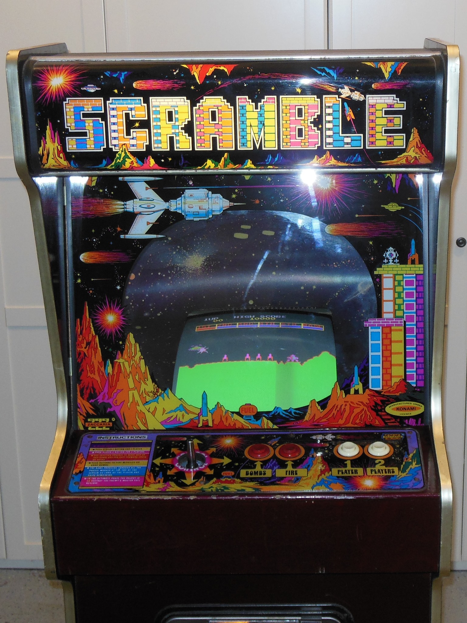
On first power on the monitor came up with a rolling picture of a running game. I'd already unplugged the marque light given the exposed wiring. There were intermittent audio beeps but the game board looked as if it was running. The coin switches rolled the counter but didn't credit the game.
|
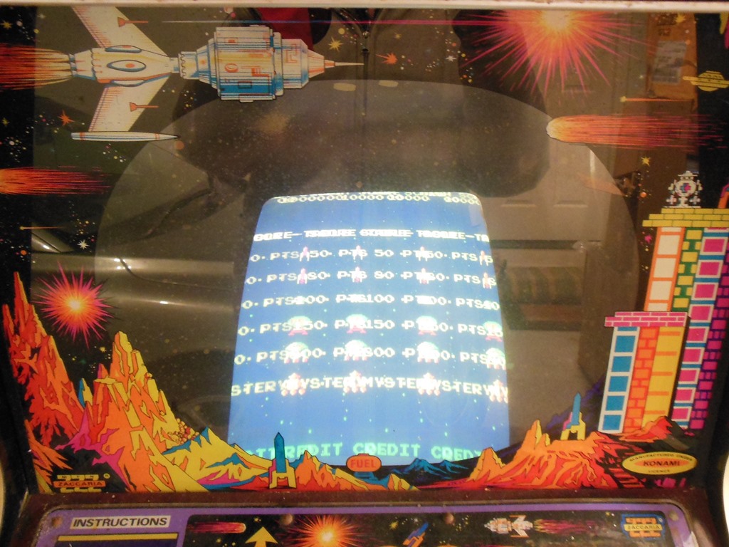
A simple tweak of the sync pot on the KT-3 monitor chassis was enough to lock the sync. The picture wasn't too bad - a little too bright and the lack of degauss suggested the degauss circuit might not have been working.
|
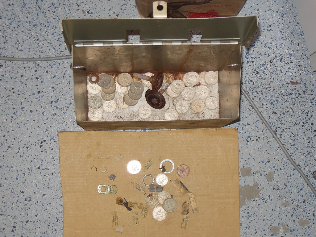
The cash box contained a nice collection of old UK 10p pieces along with the feet that had been removed and replaced with plastic castors (to be fixed later). The bottom of the cab held various lock components & EPROM labels fallen off the main board.

|
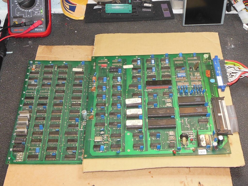
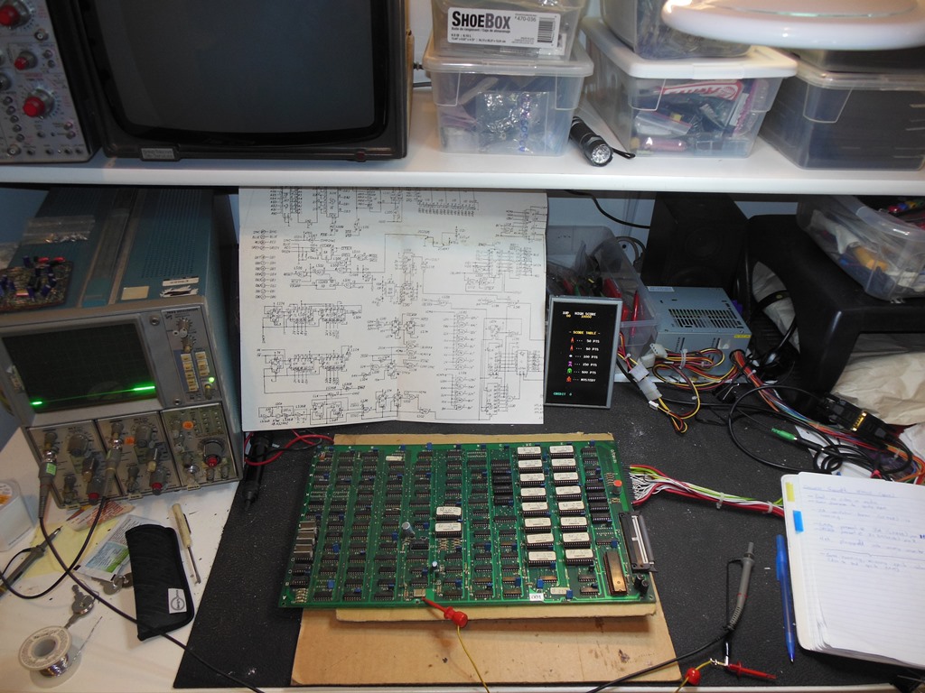
I'd found a spare Zaccaria Scramble PCB set to use as a spare for this game so I started with this board first to bring up the Arduino ICT on it. On power on the board was running with missing sprite colours and no audio. Starting with the audio issue, IC 1D (8255) pin 2 was active indicating audio commands from the main board were being issued. However, there was no audio output on either of the AY-3-8910 audio output pins. Testing with the ICT in the audio board found no issue - ROM, RAM and AY OK. I speculatively swapped around the two 8255s (IC 1D & IC 1E) and the audio came to life, suggesting one of the 8255 was bad (the sockets looked OK). Audio and inputs were all working now so I left as is (since one 8255 is used mostly input and the other mostly output, it's possible that 1D had bad outputs but good inputs and thus OK in the other position). Though the audio was generally working, the audio quality was occasionally poor.
|
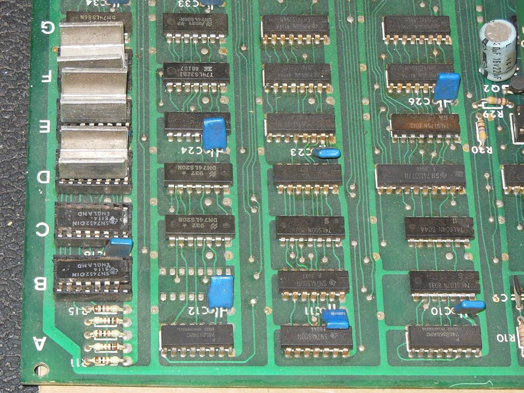
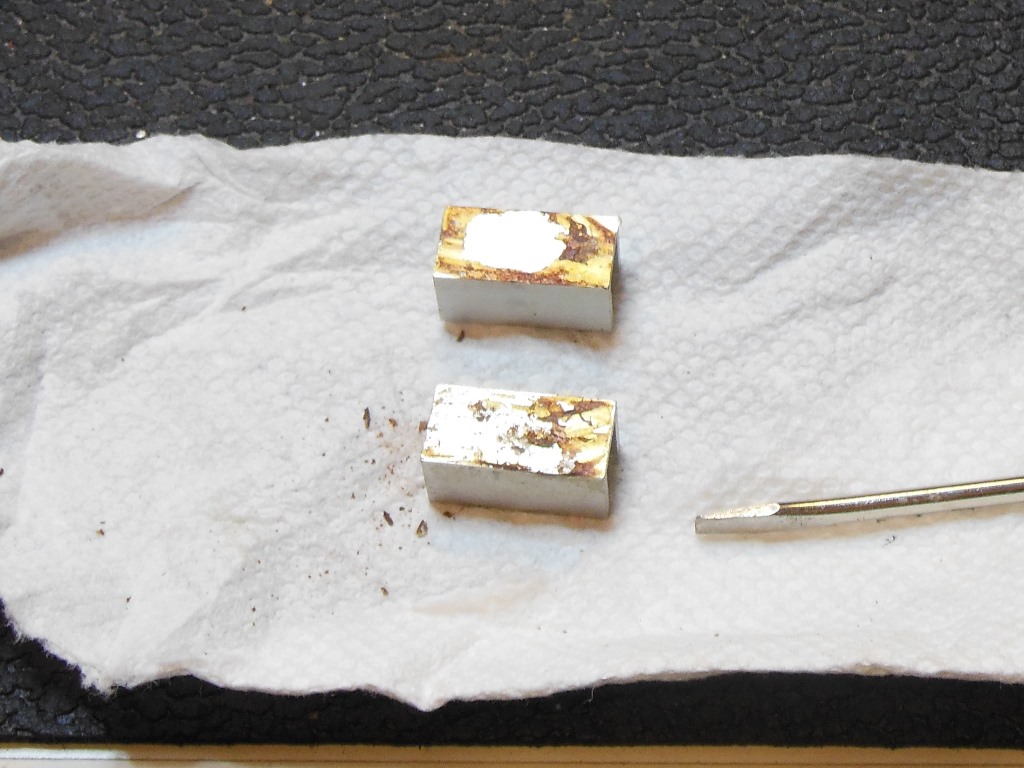
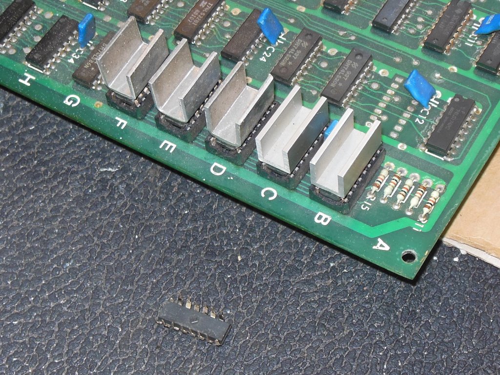
This board was missing a couple of sprite RAM heat sinks and one of the RAMS had a broken pin. I had a couple of almost identical U heat sinks recycled from a bootleg Galaxian that I cleaned off the glue from and attached onto the IC's. The sprite colours were restored with the new sprite RAM. Interestingly the other PCB set, #002, did not use heat sinks on the sprite RAM.

|
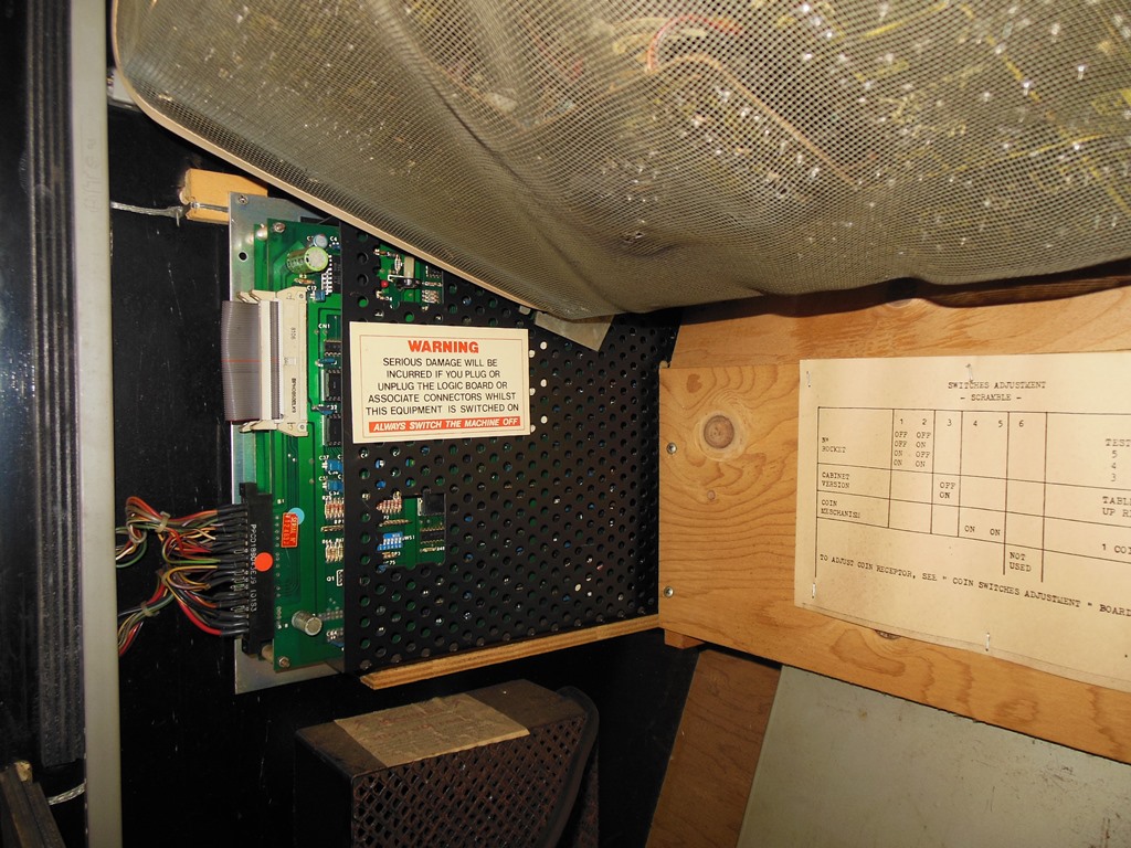
The game PCB set from the cabinet was in excellent physical condition, protected by its cage.

|
The board set had two issues - no sound and no coin up. Starting with the lack of coin up, the Arduino ICT in the main PCB revealed that all the reads of the IC 1D (8255) returned 0x64. Swapping over the two 8255 IC 1D & IC 1E restored the input reads from the ICT and allowed the game to be coined & played with no further input issues. Since I'd already now seen two failed 8255 I speculatively swapped out the second 8255 at 1D that handled the audio commands and this restored audio. I concluded that AMD didn't do a great job of making 8255's in the early 80's...
|
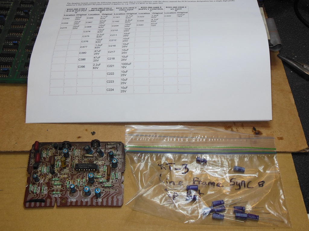
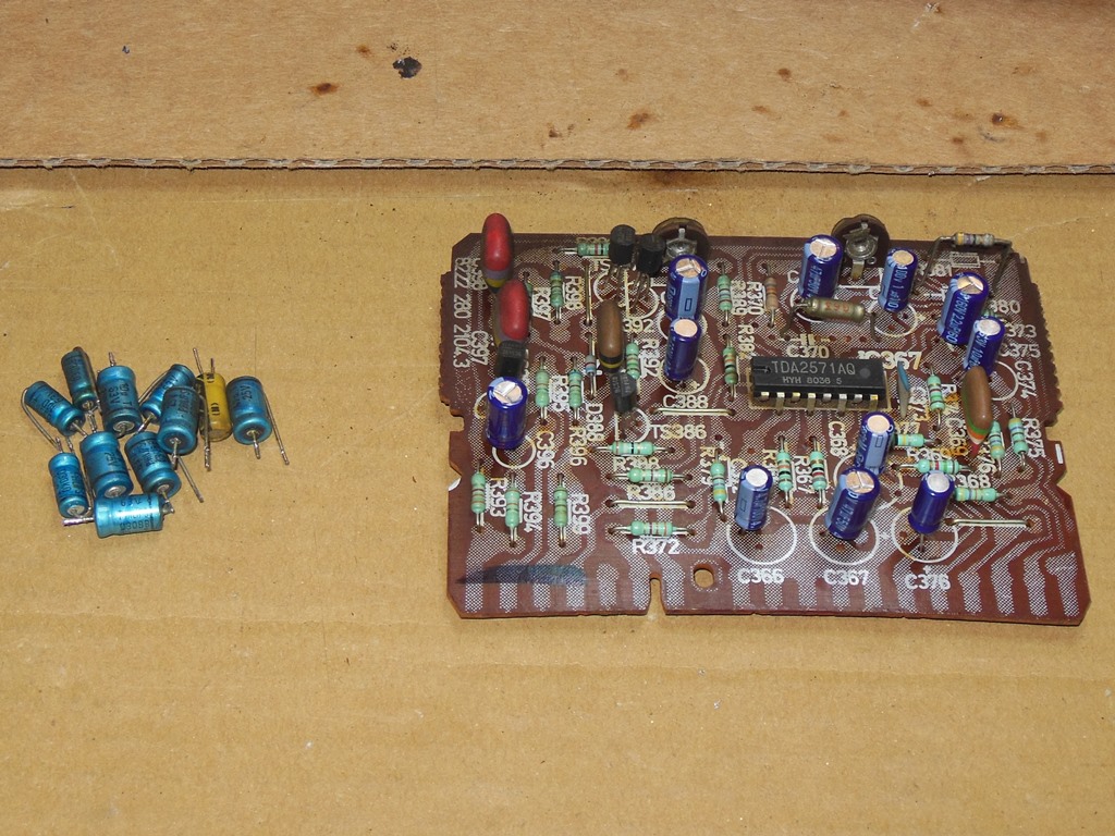
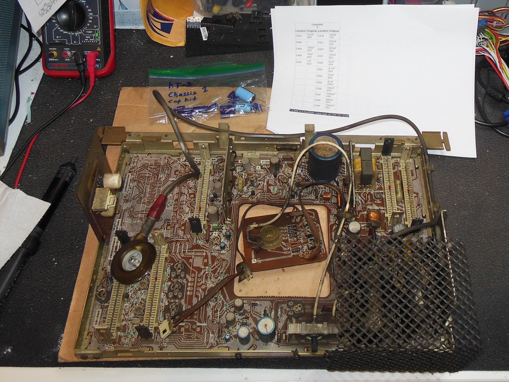
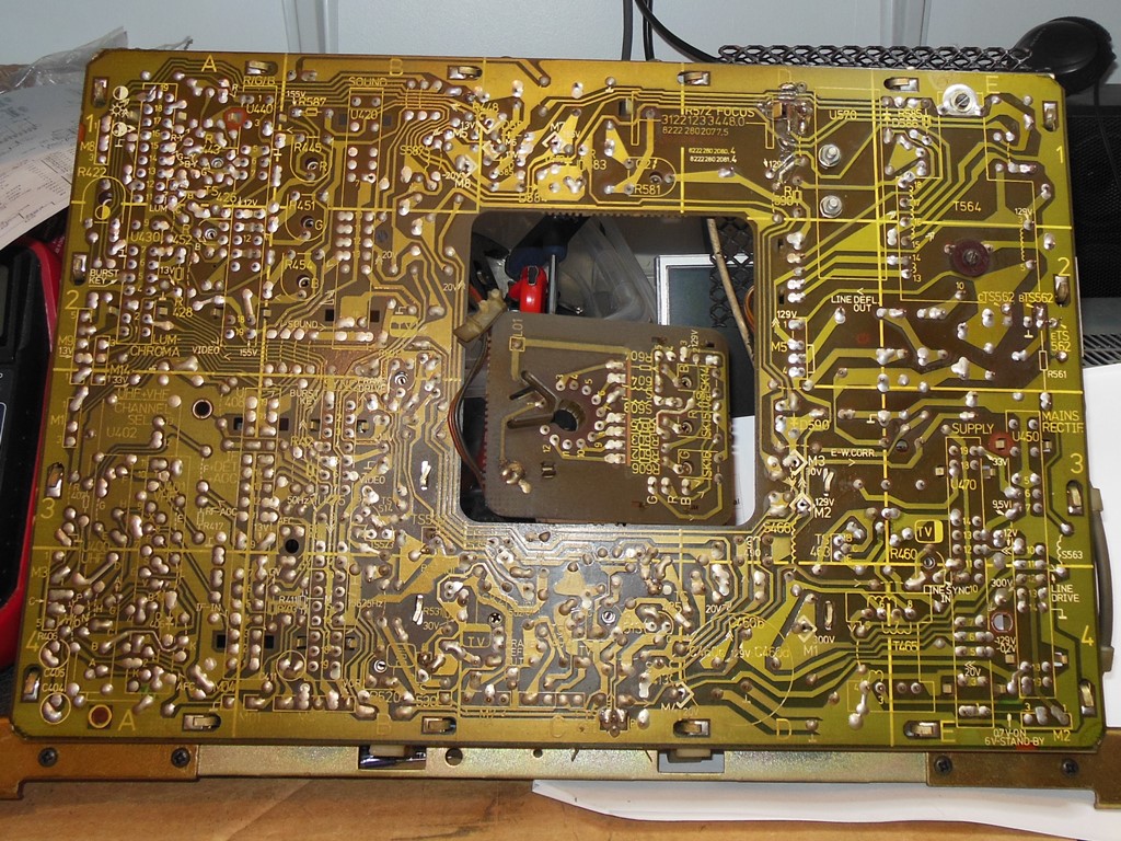
Retesting the newly repaired game board back in the cabinet found the monitor vertical sync was unlocked again. This time, tweaking the sync pot wasn't able to fix the problem and I suspected a problem with the line-frame sync daughter board. I started off with a cap kit on this board alone that turned out to be sufficient to solidly fix the vertical sync. Attention turned back to the game board that was also working properly with no further sound problems.

|
I applied cap kits to the remaining Philips KT-3 daughter boards.
|
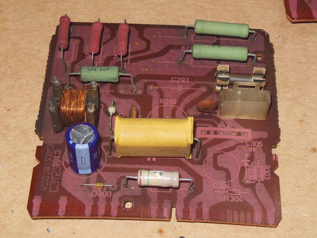
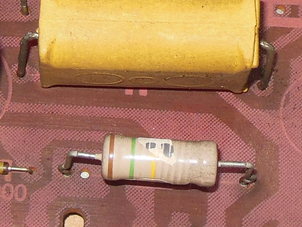
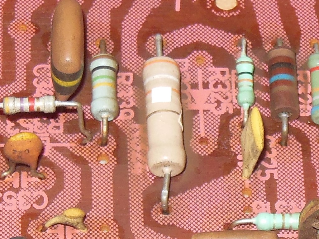
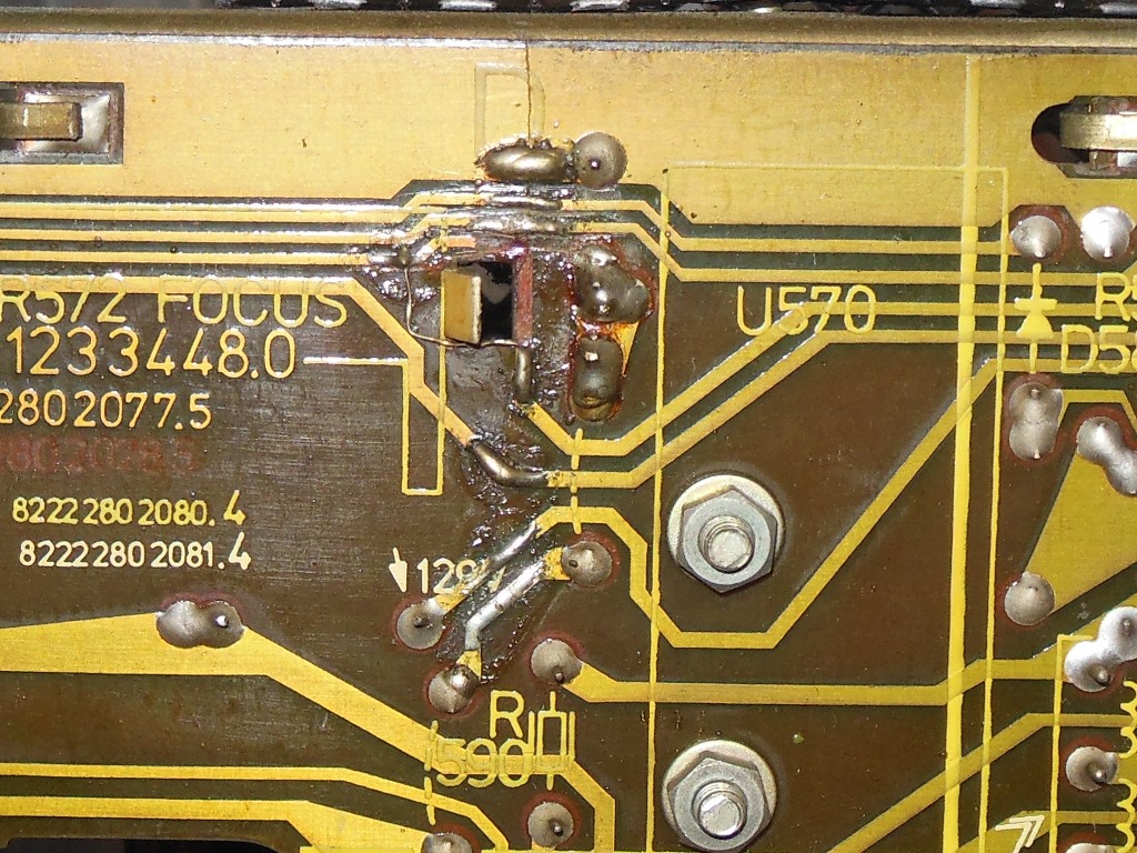
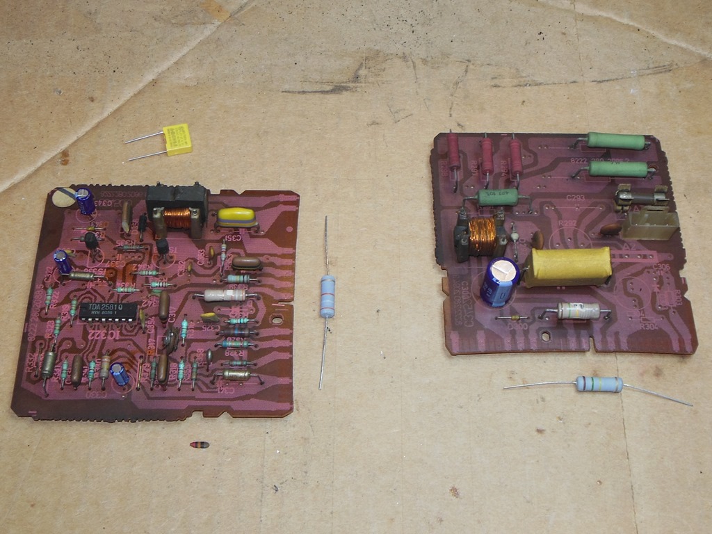
There was screen burn on the monitor CRT and the chassis had a lot of thermal discoloration suggesting that it had seen a lot of operating hours. Whilst fitting cap kits I noticed two ceramic power resistors with cracked & disintegrating bodies and one split poly capacitor for which I ordered replacement parts.

|
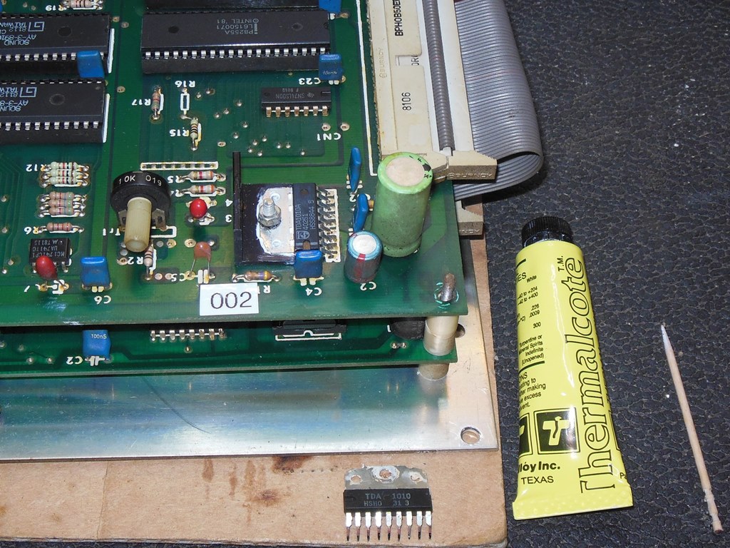
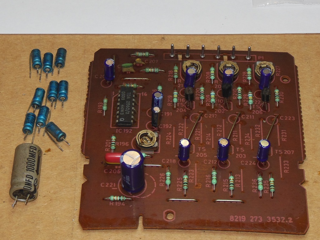
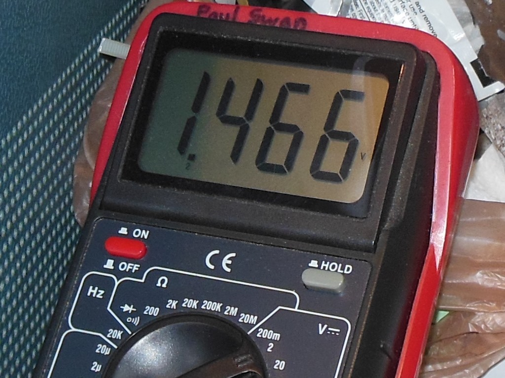
Almost identically to board #002 this board also had intermittent scratchy audio that traced through to the amplifier input. Similarly this was fixed by replacing the audio amplifier capacitors. Since it seemed suspicious that two different boards appeared to have the same issue with audio capacitors I checked the voltage across the 6.8uF capacitor linking the pre-amp stage to the power amplifier and found it to be a reverse voltage of 1.466V. A quick search online found that tantalum capacitors can break down with more than 0.5V of reverse voltage.
|
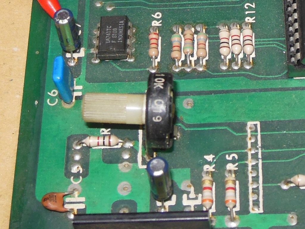
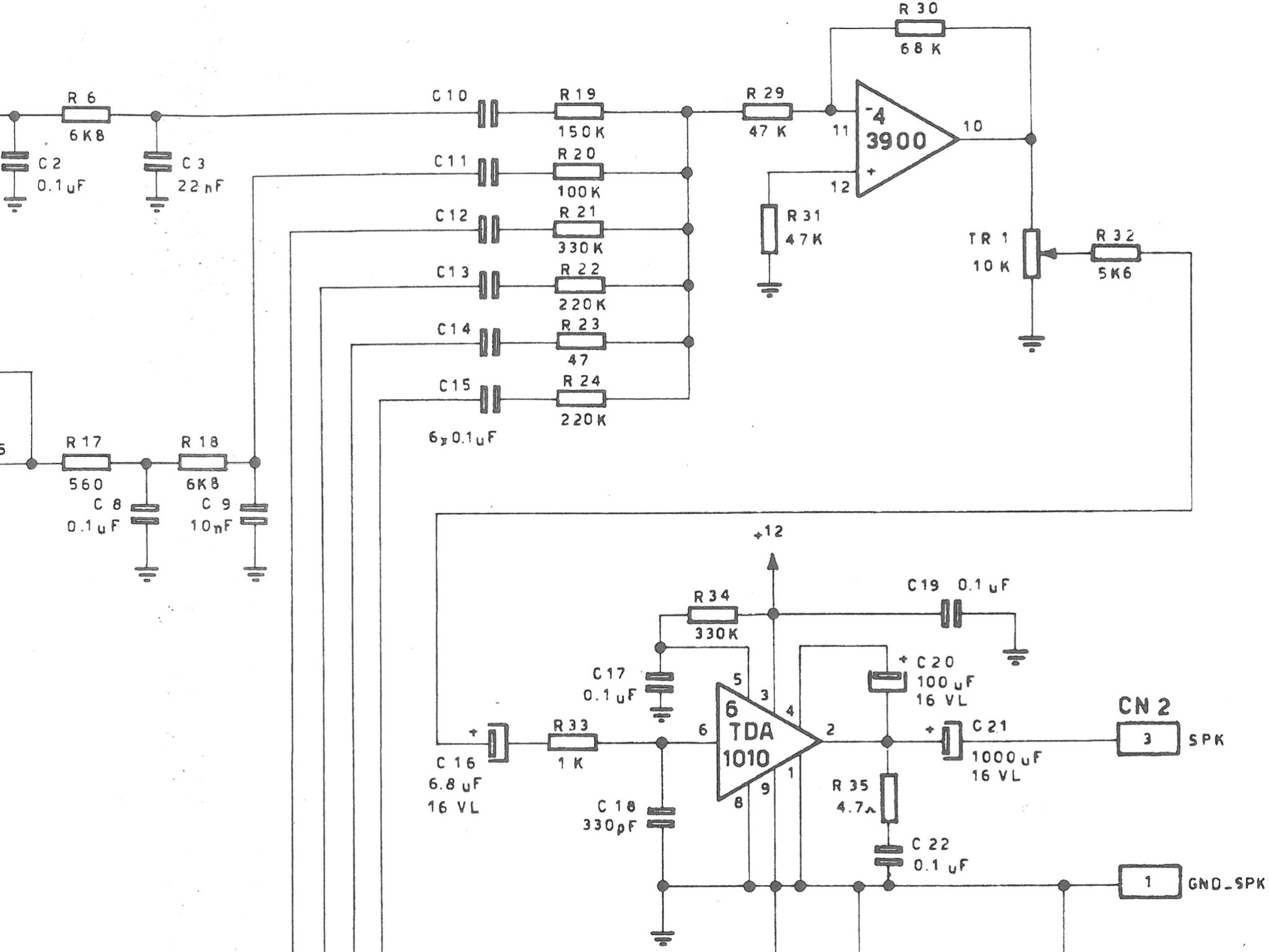
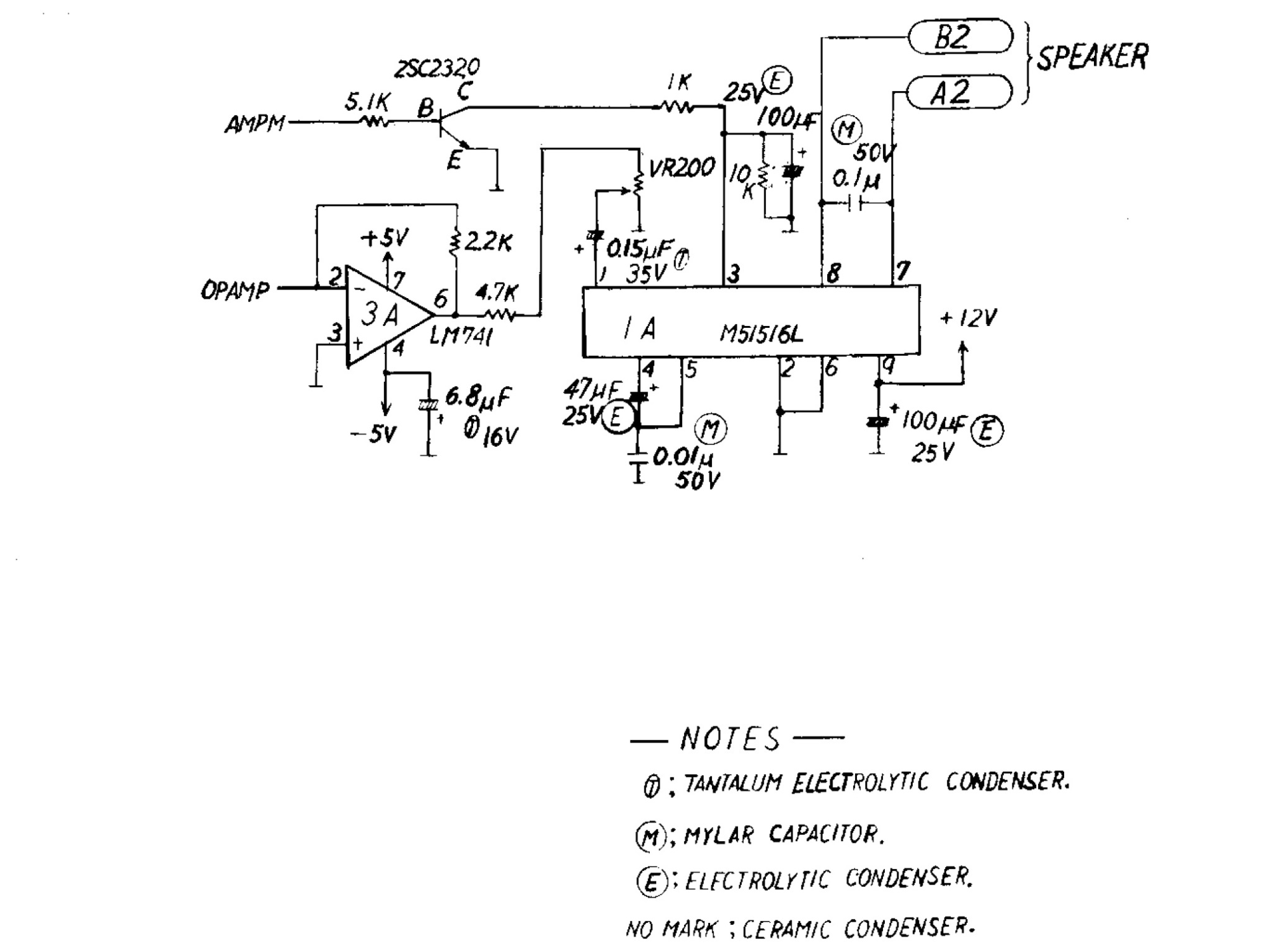
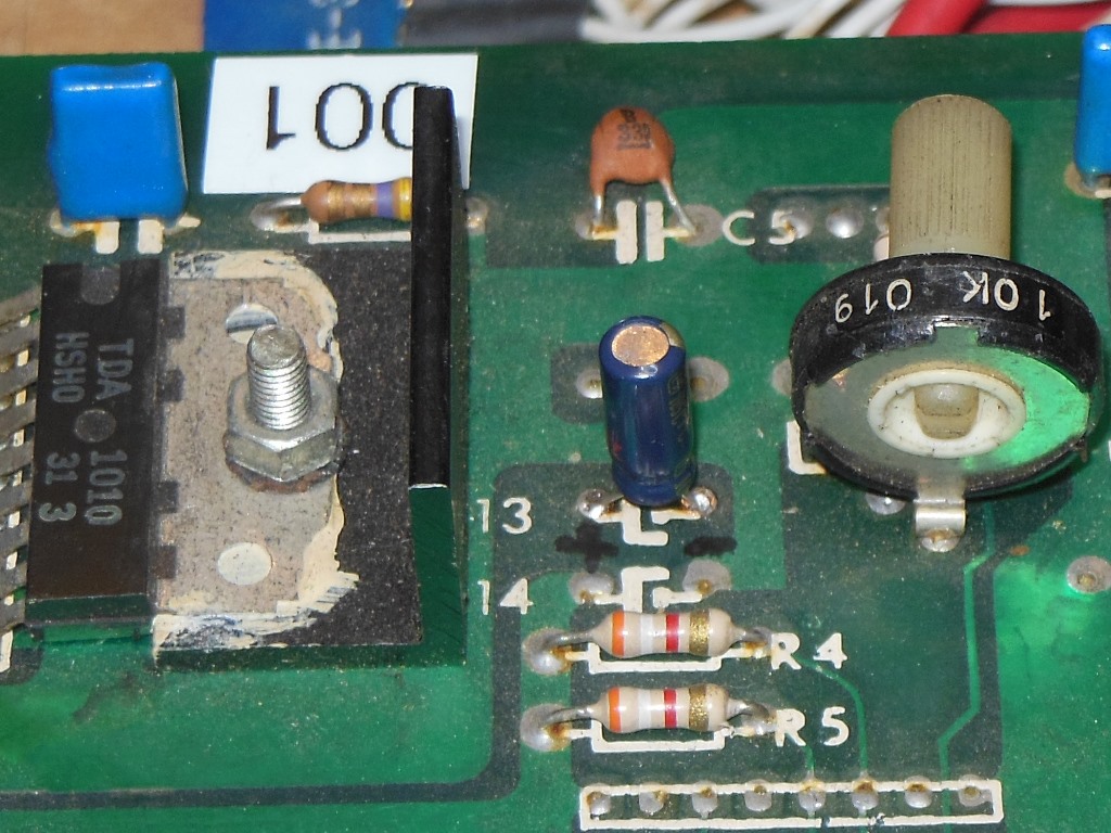
When Zaccaria copied the Scramble hardware for their own run of the PCB they made two major changes - replacing the 2716 on the main PCB with two rows of 2708 and replacing the M51516L audio amplifier with their usual TDA1010. Having spent a couple of days chasing audio dropout issues it looked like they made a design mistake. On their in-house designs the pre-amp stage was a +5V/0V supplied op-amp (~2.5V DC output offset). On the Scramble design the Konami pre-amp stage is a +5V/-5V op-amp (0V DC output offset). The DC input bias on the TDA1010 is about 1.4V and thus that would make the tantalum 6.8uF cap in between the op-amp and power amp the wrong way round on Scramble. The two capacitors I'd simply replaced as was I removed and swapped around to correct for the mistake and hopefully prevent a repeat failure in this circuit.
On retest of this board I discovetred that it intermittently lost video sync and the game stalled. When cold the game would lose sync but recover it when warm. Given that the game also stalled I suspected a problem in the video counters that were also causing the VBLANK interrupt to stop firing. Breaking out the freezer spray on the video counters quickly isolated IC 6M (LS161) as the culprit. IC 6M pin 11 (16H) was bad when the IC was frozen. Replacing IC 6M (LS161) fixed the sync.
For future reference I dumped the Zaccaria Scramble ROM set.
Zaccaria Scramble ROM Set (14KB).
|
The Philips KT-3 main monitor chassis looked in good condition aside from a split PCB repair that had been performed sometime in the past. I did some minor tidying up of that repair. The cap kit was fitted and the daughter PCB connectors reflowed.
|
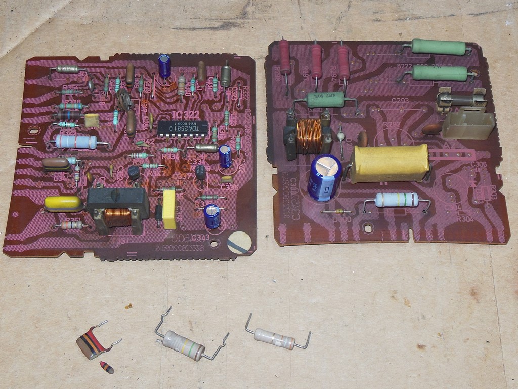
The replacement power resistors and capacitor arrived so I replaced the crumbling ones from the two power daughter PCBs. With that completed the chassis was reassembled with all its daughter cards fitted ready for reinstallation back into the cabinet.
|
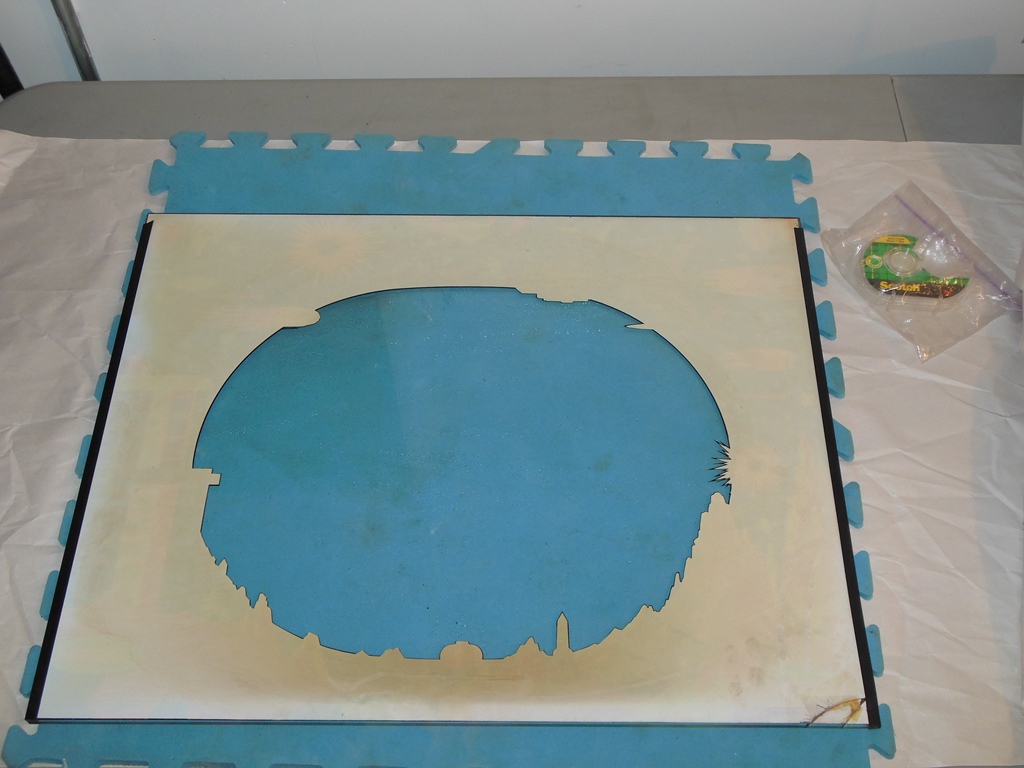
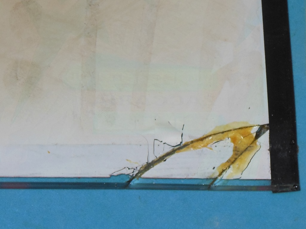
I'd intended to remove the monitor glass for cleaning and scanning as usual, however this glass had been cracked in the corner and then repaired by gluing the fragments back together and also gluing the side runner to the glass. Since I wouldn't be able to get a full scan with the side runner in place and there was already a scan and restored vector file available for this artwork I decided not to risk attempting to undo this work and leave it as is. The paint was peeling in the area of the fracture so I used a piece of clear tape to hold it in place.
|
The monitor glass side wall had also been chipped away all the way along. I hazarded a guess that a prior owner had overtightened the control panel clips and the overhang of the side wall guide over the bottom guide had chipped off the lower corner. Having cracked the glass, the prior owner had then chipped off the side wall guide to attempt to make it flush with the bottom guide to prevent further damage. The correct way to have fixed this is to restore the foam spacers on the side guides and not overtighten the control panel clips (that are adjustable).

|
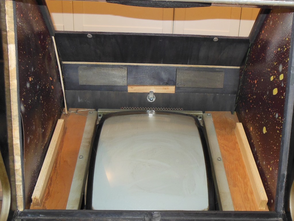
If the top access hatch wing nuts are loose it's just about possible to be able to get to them behind the monitor surround to undo them without having to un-staple the surround. In this case, the monitor surround front cavity staples were already pulled out and so the surround could be eased forward to allow more space to get at the top hatch wing nuts. With the access hatch removed I discovered that the marque light assembly was missing and an attempt had been made to hack in an overly long tube with no ballast.

|
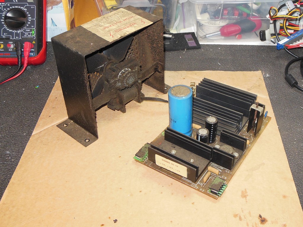
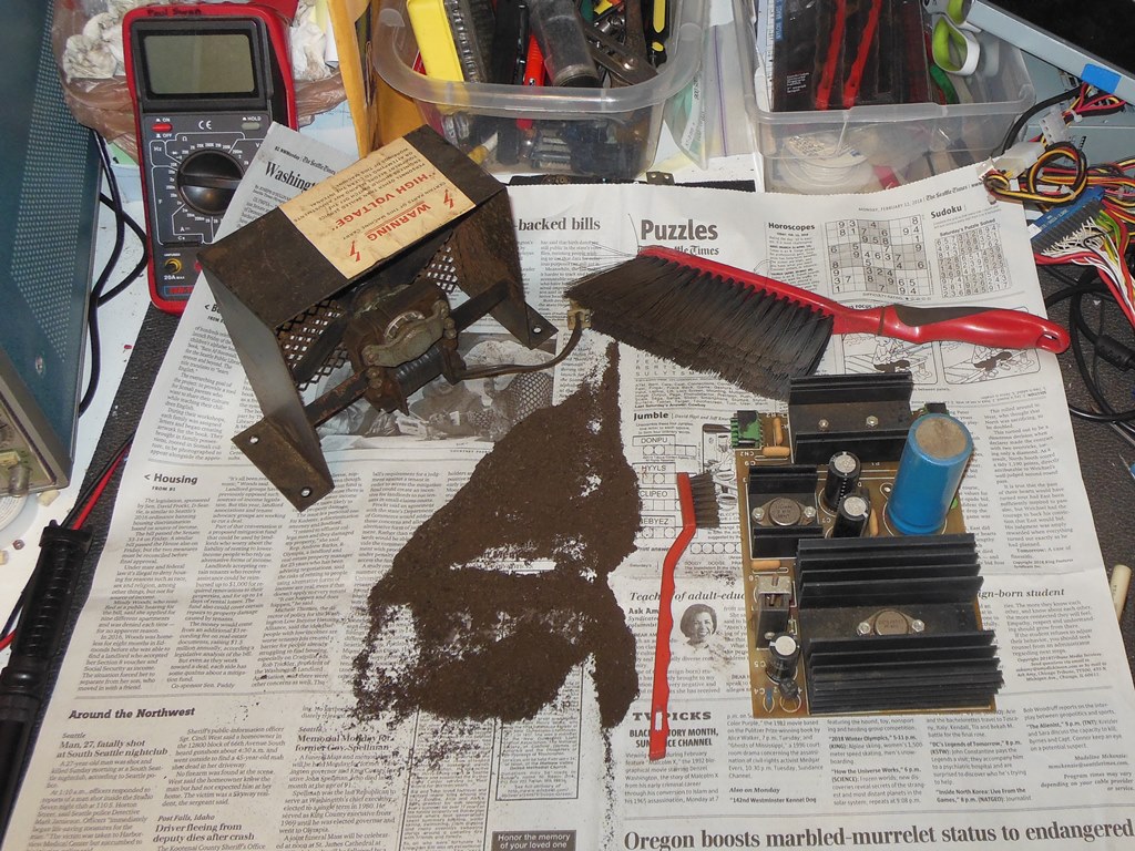
The cabinet fan and power regulation PCB were removed for cleaning. The inside bottom of the cabinet was vacuumed & cleaned.
|
The fan and power regulation PCB were dusted off with a large soft bristle brush.

|
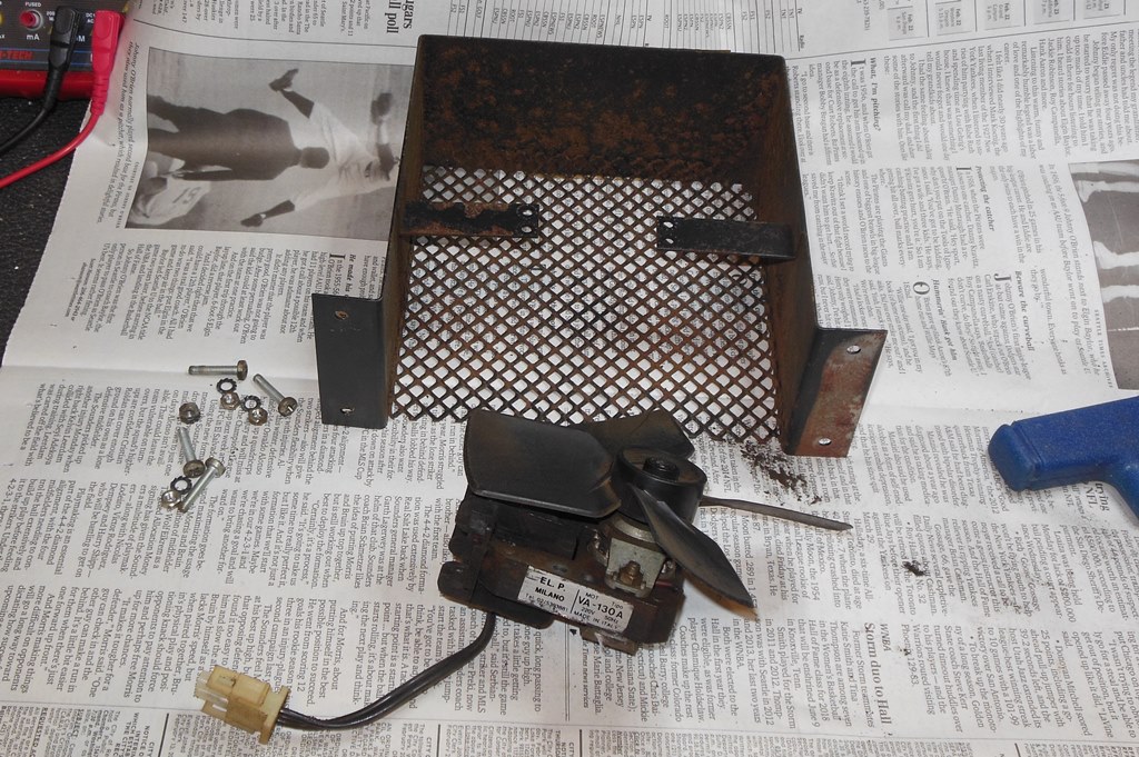
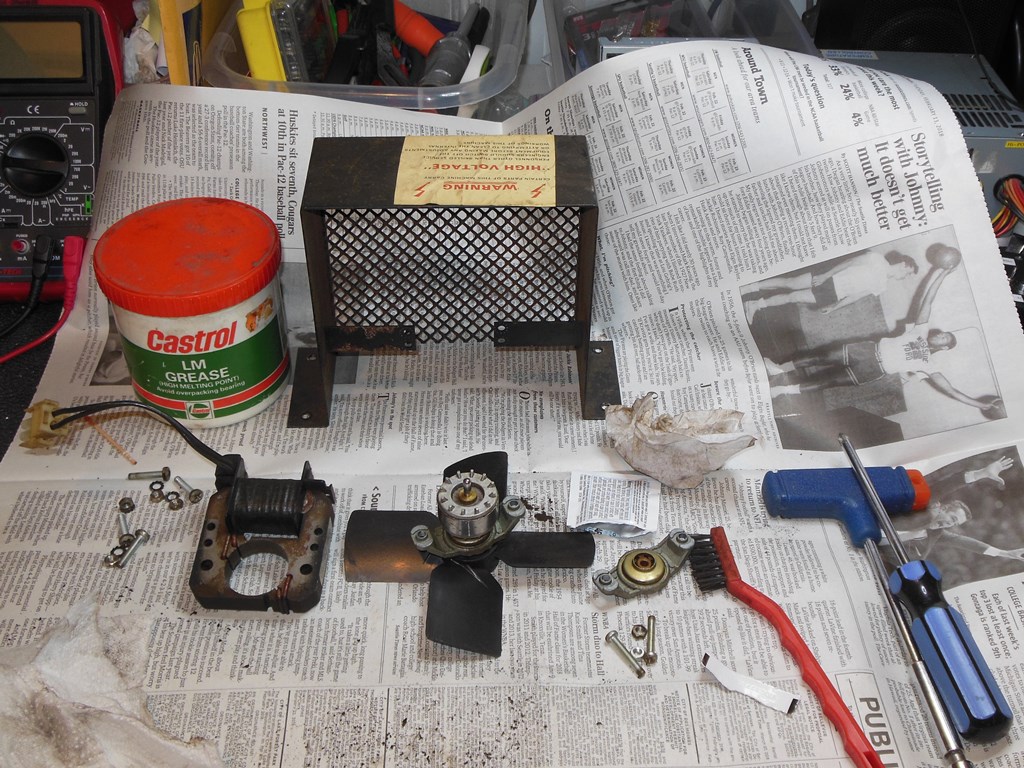
The fan motor was dissembled, cleaned and the shaft sockets and bearings greased. The shaft had some surface corrosion but looked as if it would still run OK and seemed to spin smoothly after reassembly.
|
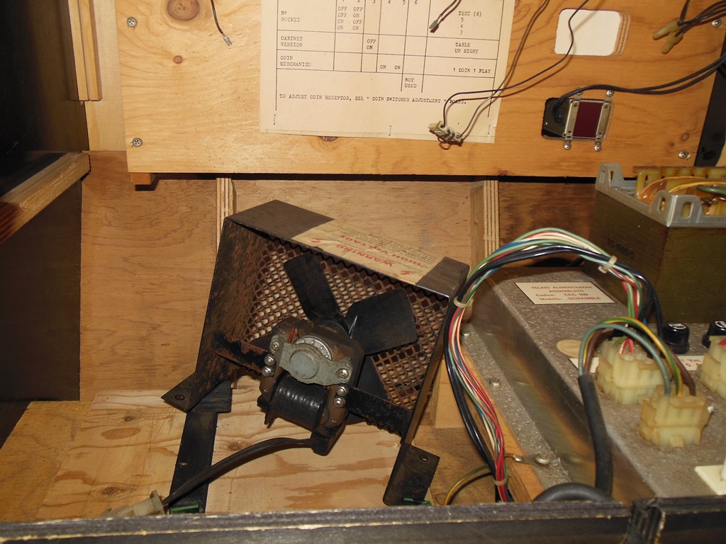
Initial testing in the cabinet confirmed that the fan was working properly. Both the fan and power supply regulation board were reinstalled back in the cabinet. The power regulation PCB appeared to be in good condition and working properly and aside from cleaning didn't need any further work.


|
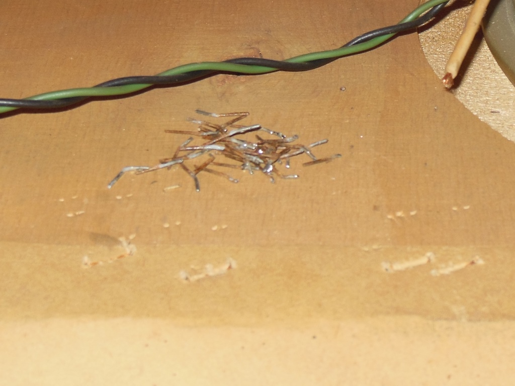
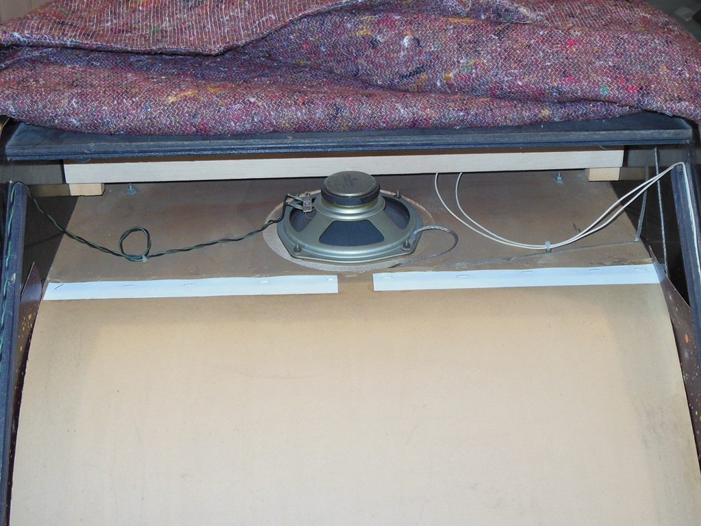
The surround cavity staples were already popped but the top staples were still as factory. To remove them I cut them in half in the center and then bent up the two halves so that pliers could get a grip on them to pull them out with as little damage as possible to the surround. In other cabinets, there is a small gap between the front glass side guides and the top but in this cabinet wood glue had sealed that gap. Instead, the surround was removed from the rear access hatch side, just squeezing out past the speaker cable.
|
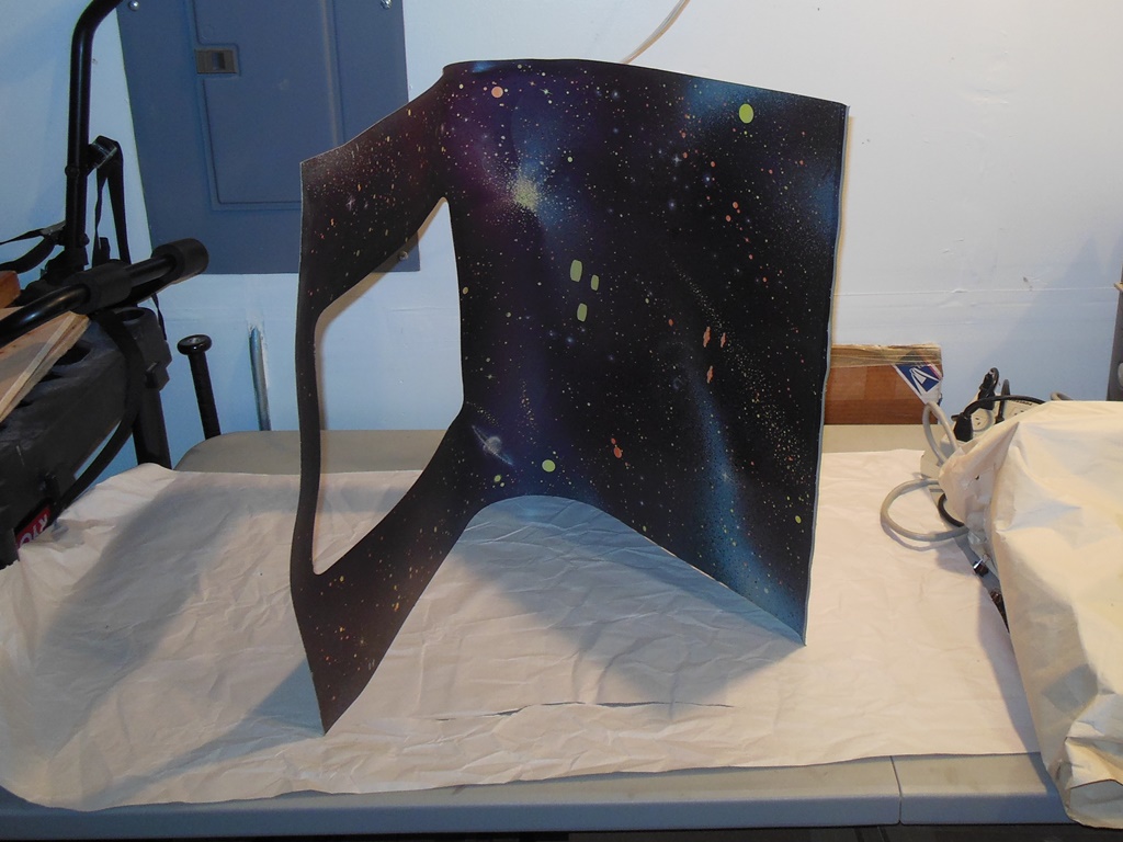
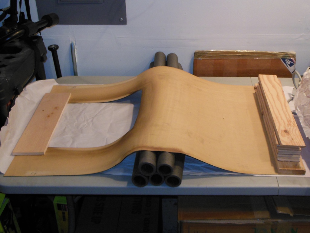
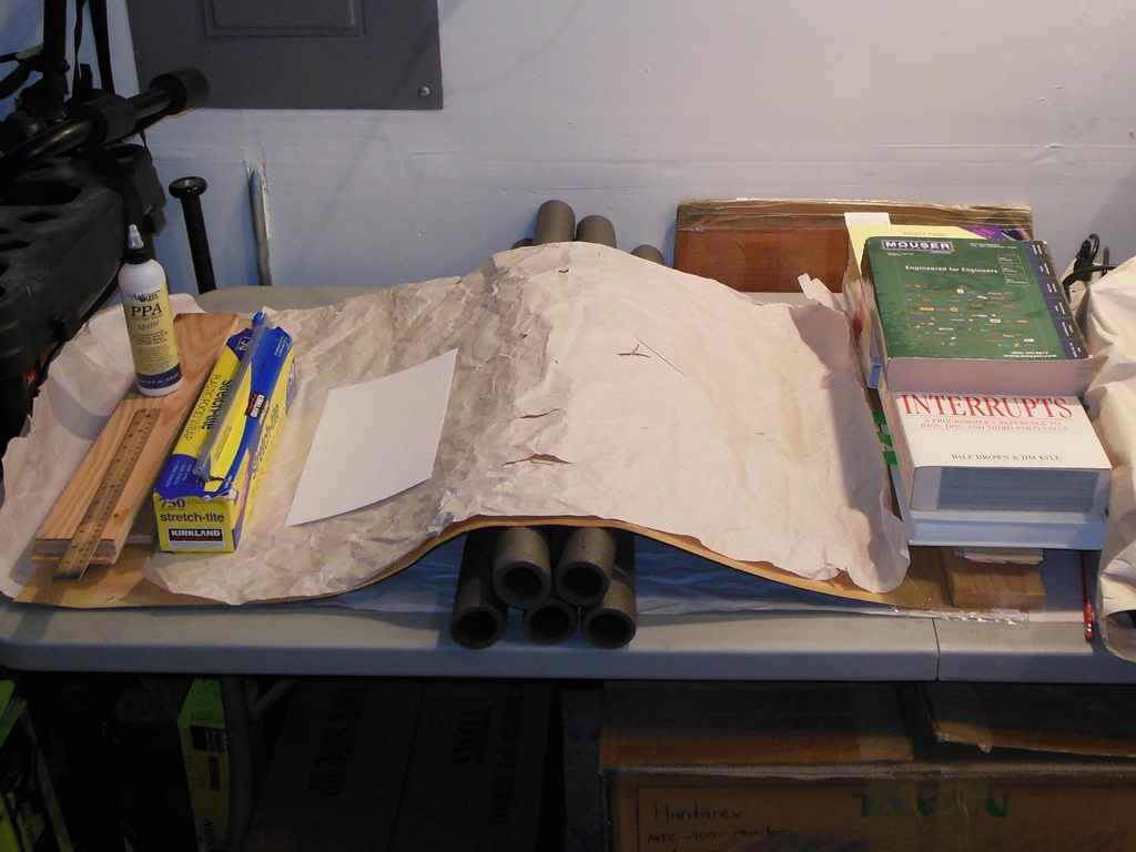
The surround had fairly rigidly curved into the cavity shape that I didn't think was safe or necessary to try and flatten out in this case. To preserve the curve a few foam tubes were used to support it. The top edge had creased along the wood line slightly and needed some reinforcement to help reduce sagging. The bottom portion had staple holes as a result of the surround being pulled up rather than the staples removed in the past that would need to be patched.

|
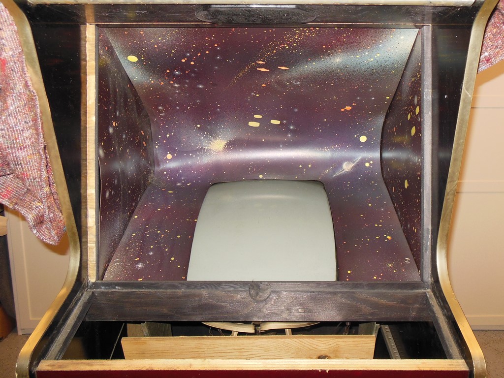
With the surround out the monitor CRT was cleaned. The CRT had some Scramble screen burn consistent with the chassis� look of a lot of hours use. The picture was crisp and clear.

|
The surround was patched with strips across the top edge and patches over the cavity staple holes, then left to set for a few days.
|
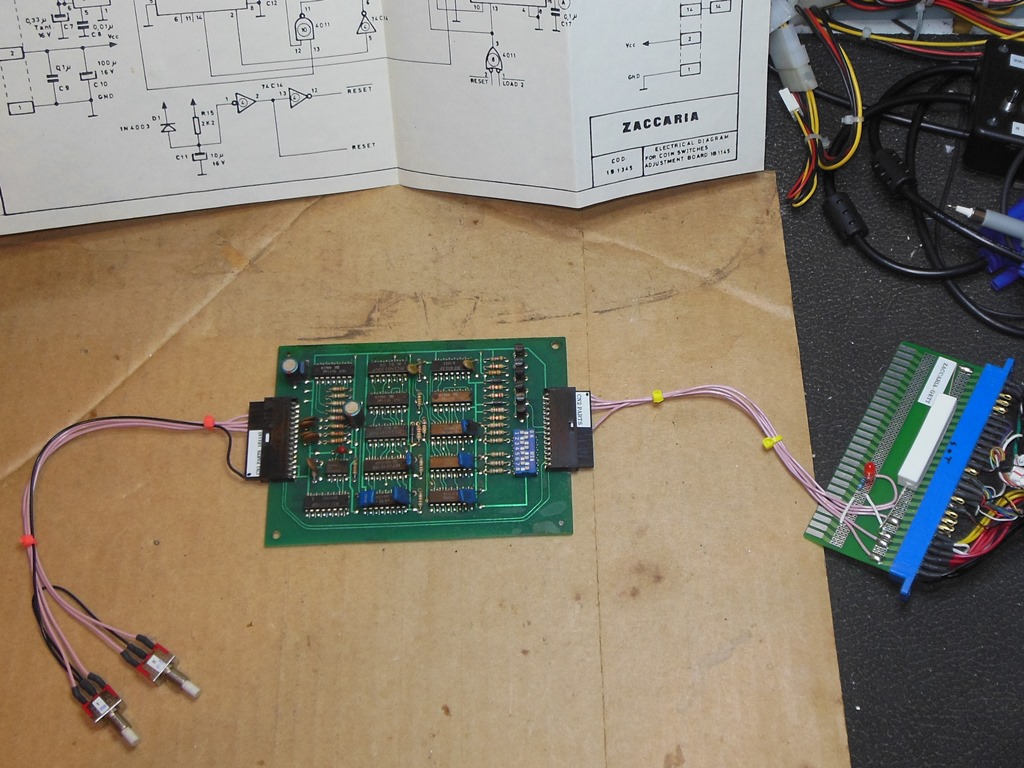
The credit board wasn't coining 1 coin 1 credit. The coin 1 switch had no effect
and the coin 2 switch issued 2 credits and 3 counter pulses. On the
bench in the test setup the credit board behaved the same way. The master
clock IC11 (NE555) was running. On toggling coin 1...
IC12 (4011) pin 11 pulsed OK.
IC13 (4013) pin 1 stayed high.
IC7 (4001) pin 3 transitioned from low to high.
IC10 (4011) pin 4 was high, pin 5 was high and pin 6 transitioned low to high.
I suspected IC10 (4011) was bad. Replacing IC10 brought back coin 1 as 1 coin 3
credits. Comparing IC1 (4089) with IC2 (4089) found the DIP switch input pins
2, 15, 14 as low, low, high. The input pins 11 & 9 were the same on both.
I suspected IC1 (4089) was bad but I had no spares and no reasonably priced ones
available that shipped to the US. I ordered some 4089 shipped to the UK and fitted
the spare credit board #001 into the cabinet for now, setting aside the #002 as a partly
working spare.
|
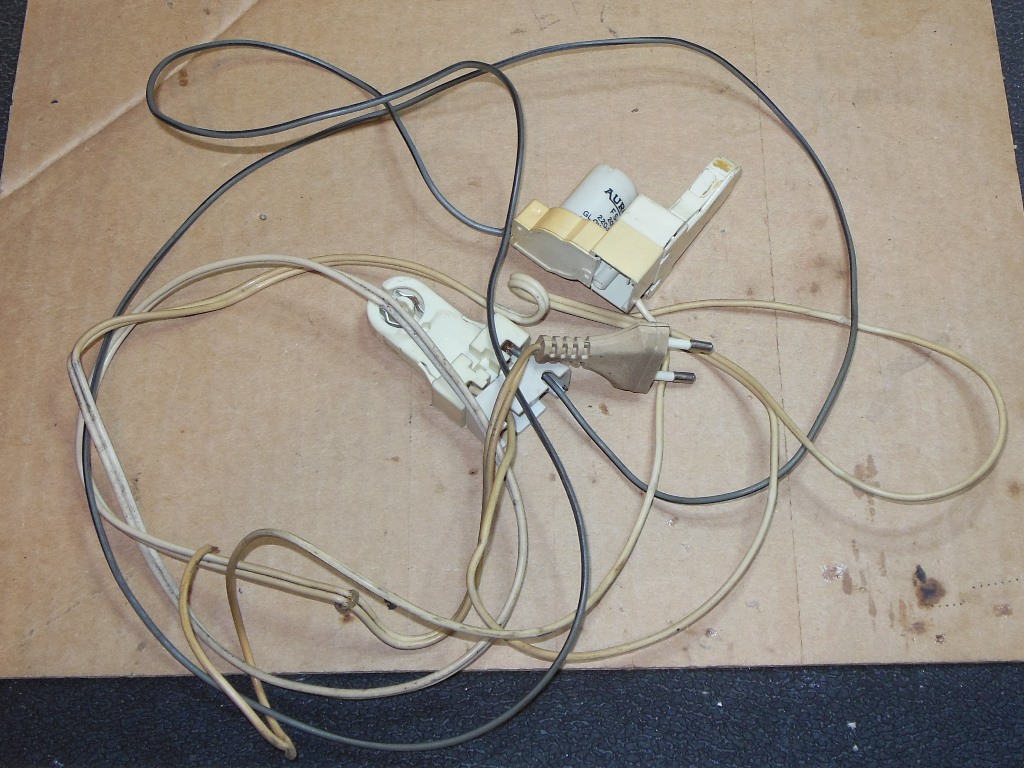
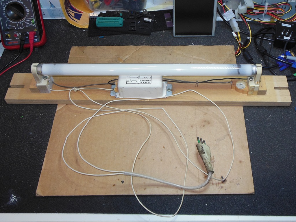
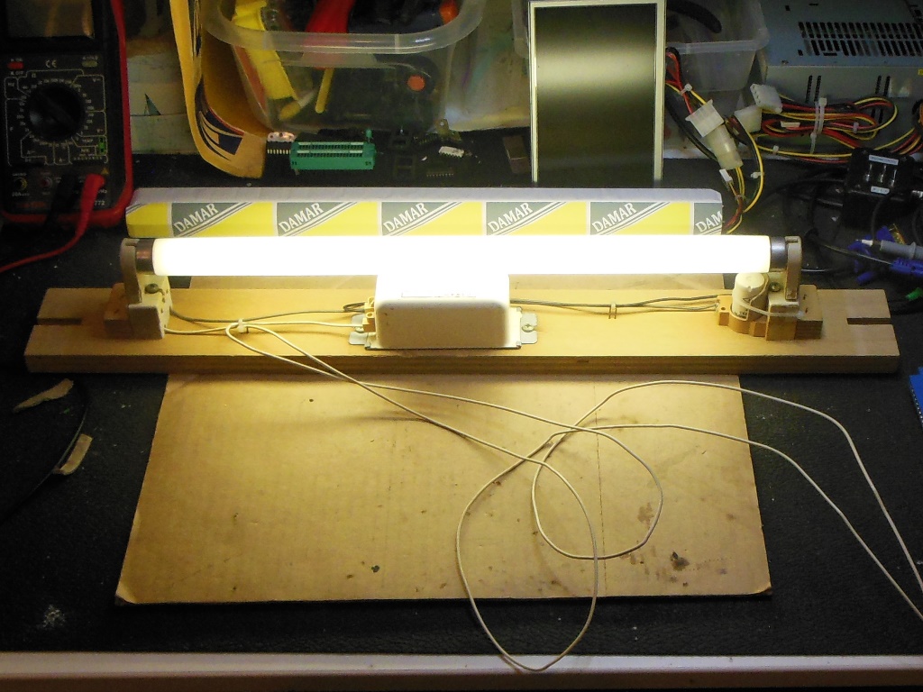
There wasn't much left of the original marque light assembly - just a portion of the wiring and end sockets. I had a spare Astro Wars (from the Duke of Lancaster raid) that I'd been using as a parts donor for various other restorations from which I removed a complete marque light assembly. A new tube was all that was needed to get it working.
|
The replacement marque light assembly from Astro Wars fit this cabinet perfectly. The mounts in Astro Wars were wing nuts through end slots whereas in Scramble the marque light assembly is screwed through solid wood. The compromise to adapt it was to use screws with a large washer over the slot. There was some damage to the marque artwork that I wanted to see with the marque light on before deciding if it needed a touch up. Since the scrape holes were not so noticeable I decided to leave the marque as it was.
|
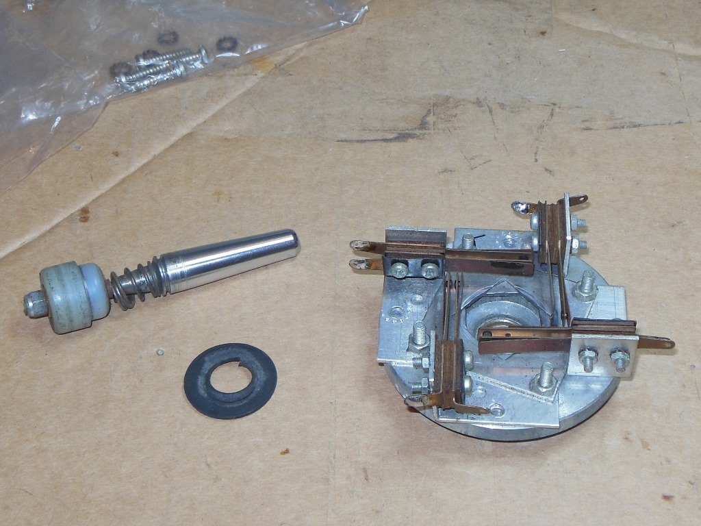
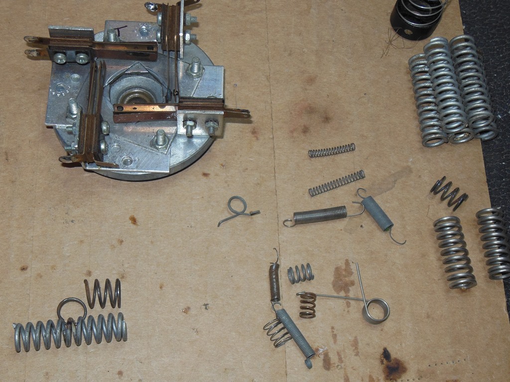
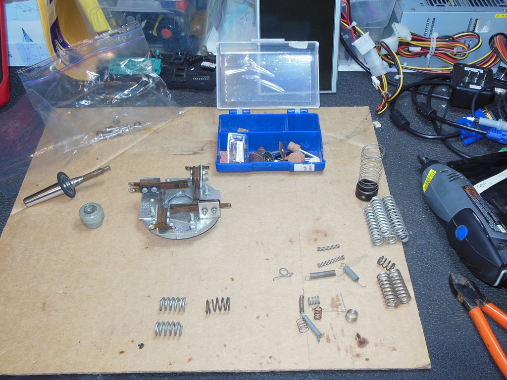
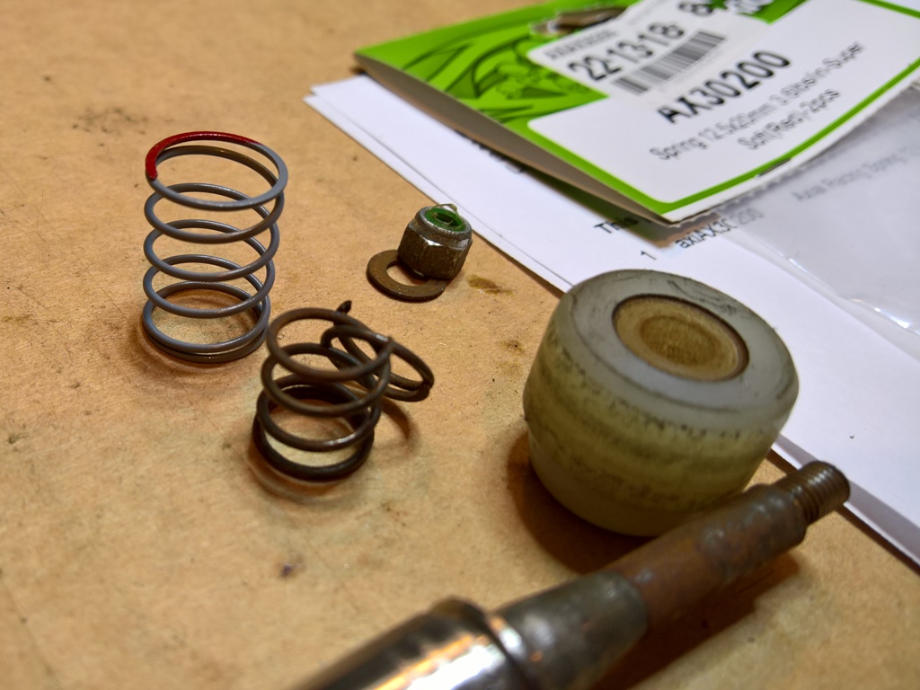
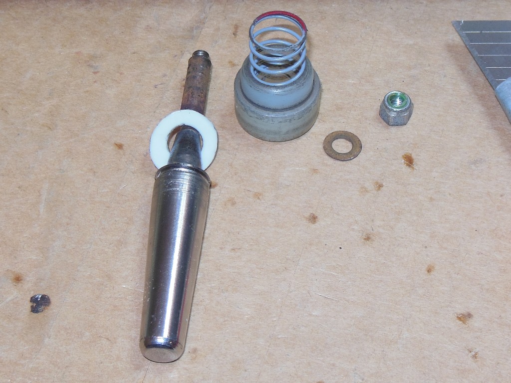
The original joystick had been replaced with a later model standard black plastic type. The original one would have been a chrome shaft model. I had a poor condition chrome shaft joystick that had been swapped out during a prior restoration that would need to be repaired to be used again. It wasn't the exact same type (according to the Scramble manual and the screw holes in the control panel) but would fit and look correct. The shaft was slightly bent, fixed with a vice and hammer. The centering spring had also snapped. I found a spring of the correct diameter in a spares box that I cut down to the correct length. Whilst this spring fit the joystick, it was much too stiff. I ordered some model car racing springs that were close to matching in size to try out next.

|
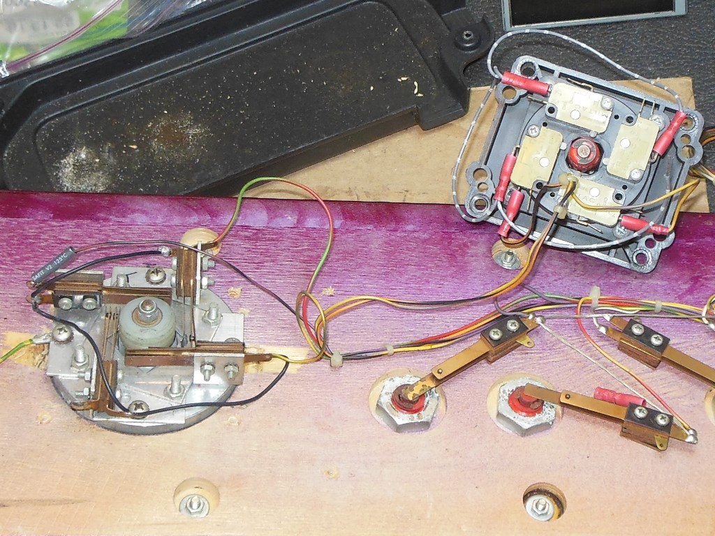
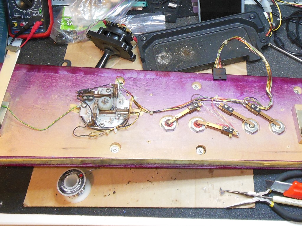
I built a credit button bracket assembly based on a 3-way button to match the 1B1145 credit PCB's NO/NC coin inputs and fitted into the cabinet attached to the 1 coin 1 credit switch.

|
The minor patching of the surrounding was all set and the surround was reinstalled back into the cabinet, feeding it back through the rear access hatch the same way that it was removed. I row of staples alone the top secured it aligned in place and the top reinforcing patches appeared to have been enough to keep the back curve convex.

|
The model racing car springs were AX30200 super soft "red" 3.6lbs/in 12.5mm x 20mm from Liquid RC. The length was a pretty good match but the diameter was slightly larger than the original spring that was 10mm in diameter and 18mm long with 5 coils. The compression seemed pretty close to what was left of the original spring. Luckily, the new larger spring was still just able to squeeze into the socket of the switch bumper. Fully reassembled the shaft centering appeared to be spot on with the new spring :)

|
The chrome shaft joystick was fitted into the control panel and the switch wiring moved over from the plastic one. Back in the cabinet the switches all worked correctly.

|
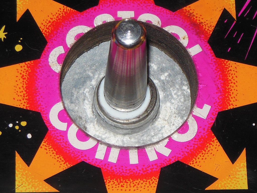
The joystick didn't feel quite right. The centering spring was good, near perfect, but the motion seemed clunky. The Zaccaria Scramble manual illustrated a slightly different chrome shaft joystick than the one I had to hand - the one in the manual had a different switch configuration but the base plate and shaft looked the same. The manual showed a Teflon insert fitted into the top of the shaft socket that was missing from my joystick. I ordered a flat sheet of 1mm Teflon PTFE from eBay with an idea to attempt to make a washer-like part as a replacement for the missing insert.


|
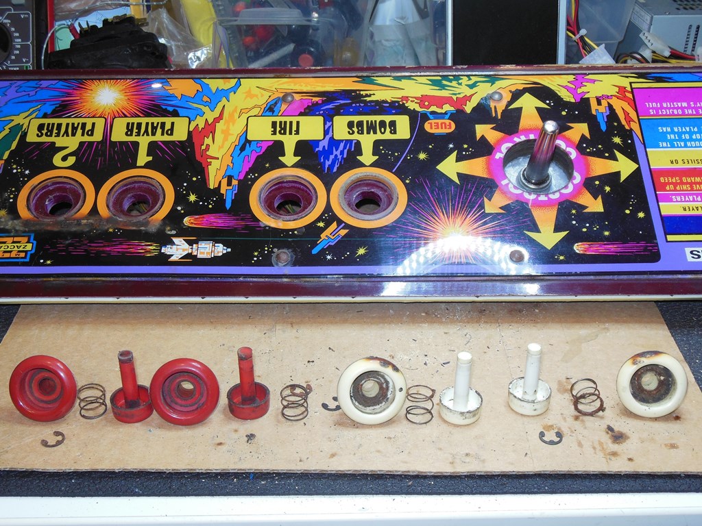
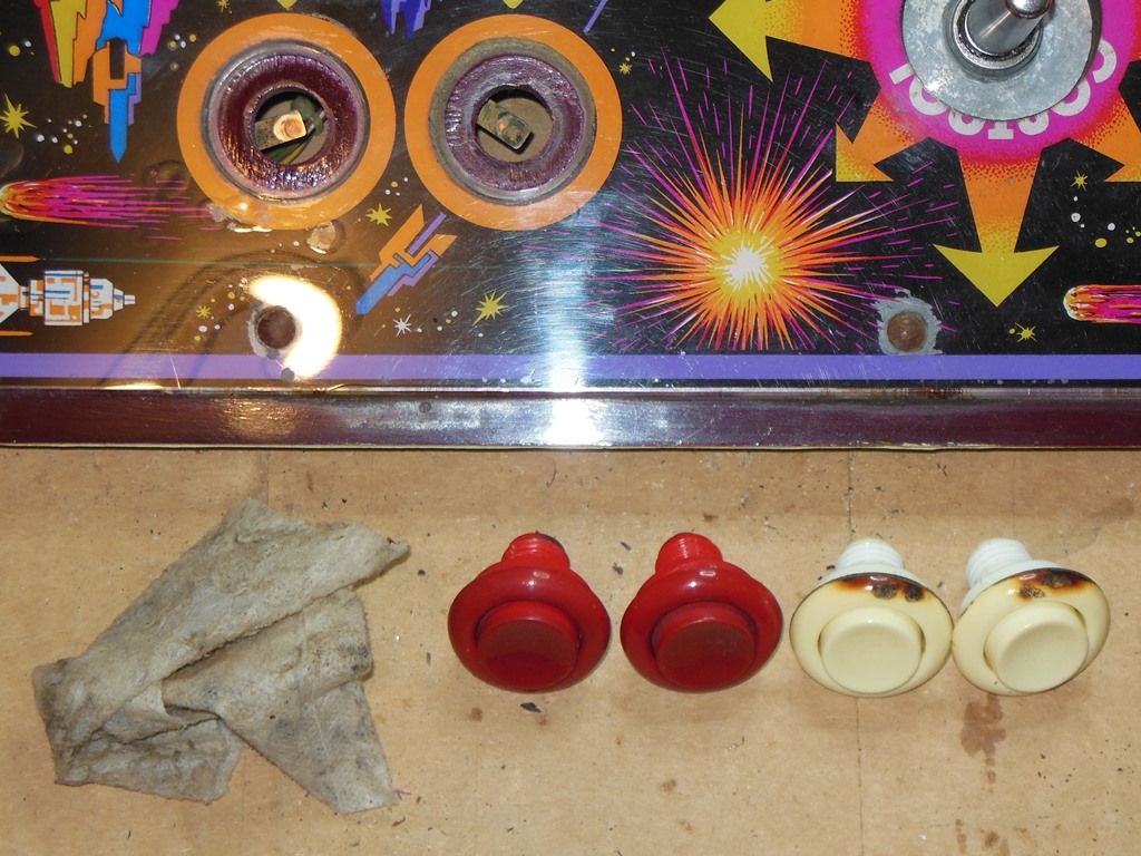
Cigarettes left to rest on the player 1 & 2 start buttons had burned the tops of the buttons and the top of the overlay. The heat had also cause the overlay to curl up. To fix this I used a heat gun set to half power to gently heat this section of the overlay until it became soft and then pressed it back down with a cloth until it cooled again, fixing it back flat. I was by no means perfect but substantially better than it was, barely noticeable.


|
The control panel had the remains of an old sponge padding strip for seating the panel against the monitor glass evenly. A strip of adhesive foam tape served as a replacement for it.
|
The buttons had accumulated a varying amount of dirt & nicotine so they were disassembled and cleaned. Some of the springs were a little rusted but still all functional. The player start buttons were pretty badly scorched along the top but left as is, a battle scar.
|
The remaining interior components were screwed back into place and the monitor protective net reattached.
|
The restoration was almost complete and the machine fully working.

|
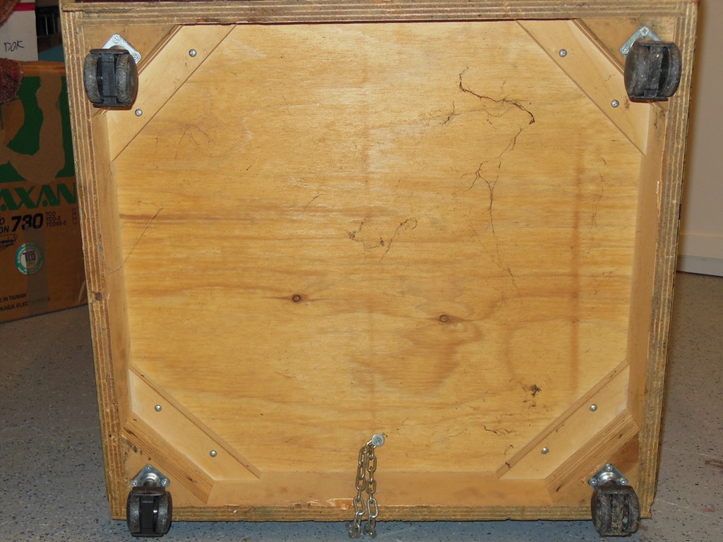
The cabinet already had castors fitted, but light duty plastic ones that wouldn't survive transport for the show. These were replaces with steel industrial castors that should hopefully last longer.

|
I'd ordered a sheet of 1mm thick white Teflon PTFE from which to make a shaft washer. The material was soft enough to cut with scissors and a craft knife. The shaft has a conical section that allowed the washer to seat firmly and the PTFE soft enough to allow the washer to deform slightly to match the curve of the shaft. Fully assembled, the clunky motion was gone and the joystick felt much better.


|
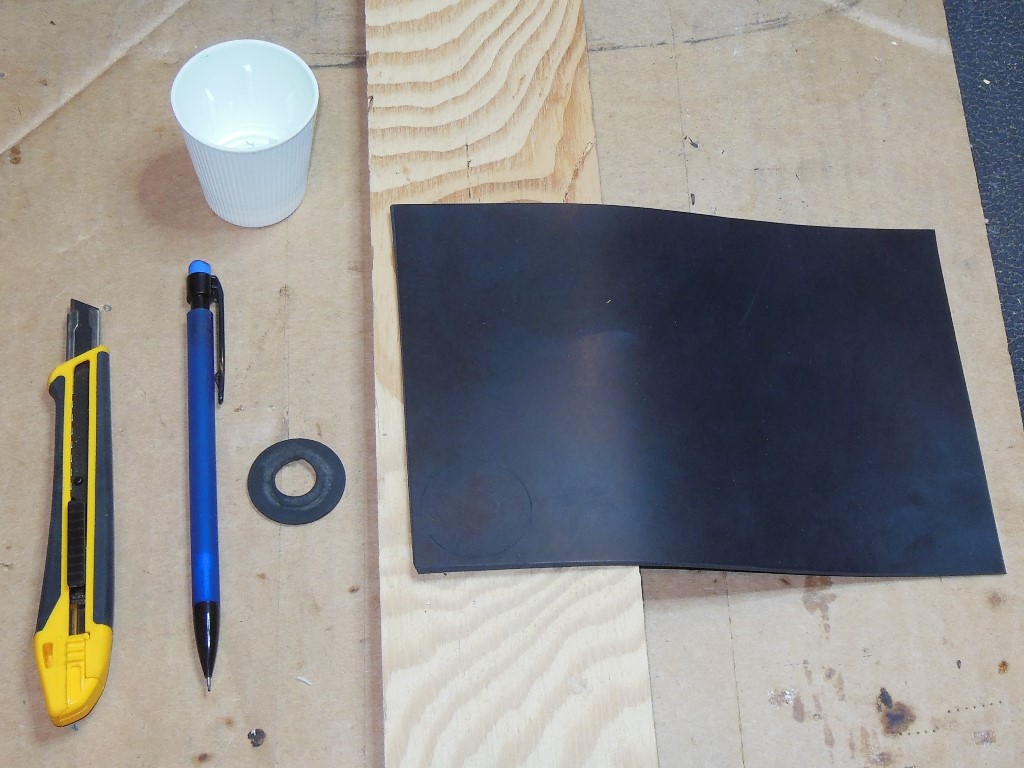
I'd ordered a sheet of 1/16" thick black neoprene sheet from which to make a dust cover. The material was soft enough to cut with scissors and a craft knife. The shaft has a small ring groove for the dust cover to lock into and I cut the hole on the small side to ensure a tight fit into the groove. Fully assembled, the dust cover stretched to be slightly convex but since the shaft hole had been drilled out larger the dust cover didn't catch on anything and looked OK.
With the last of the minor items taken care of the game was ready for show time.