|
|
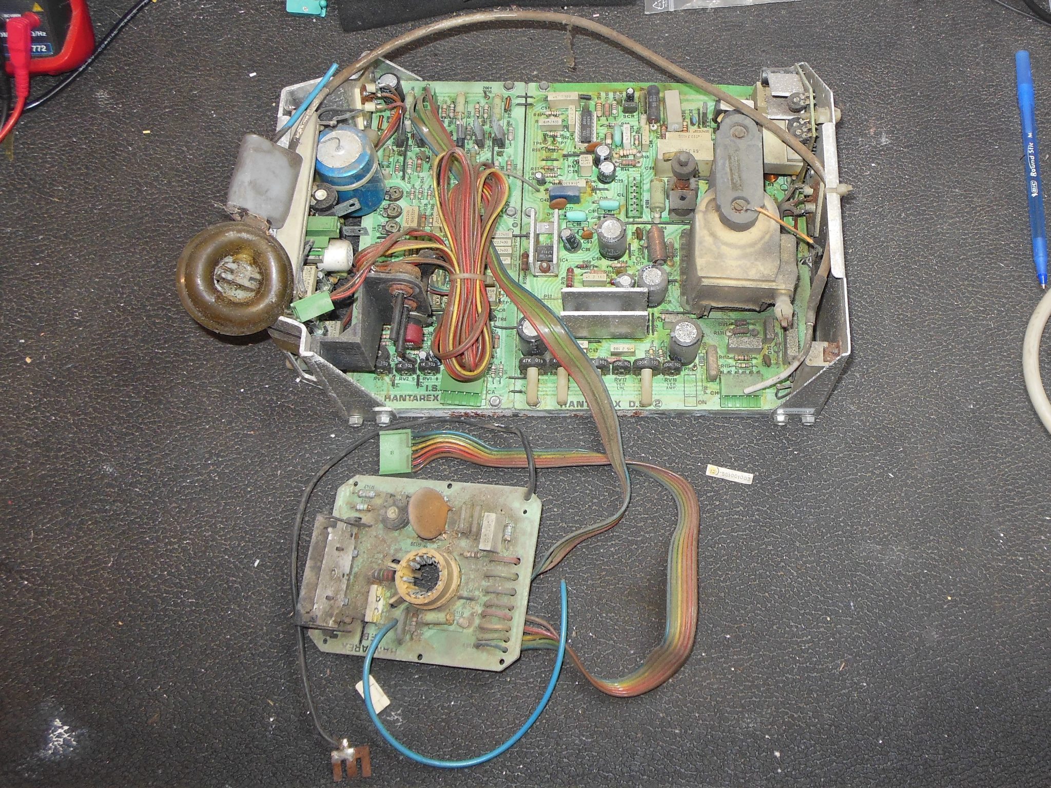
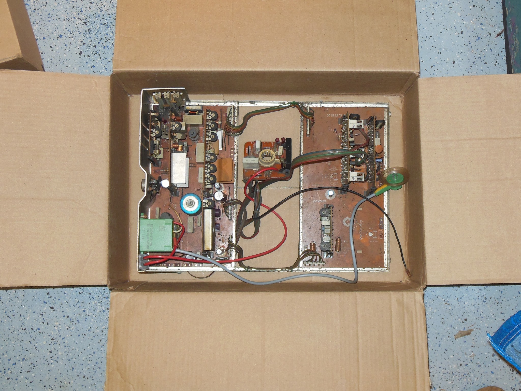
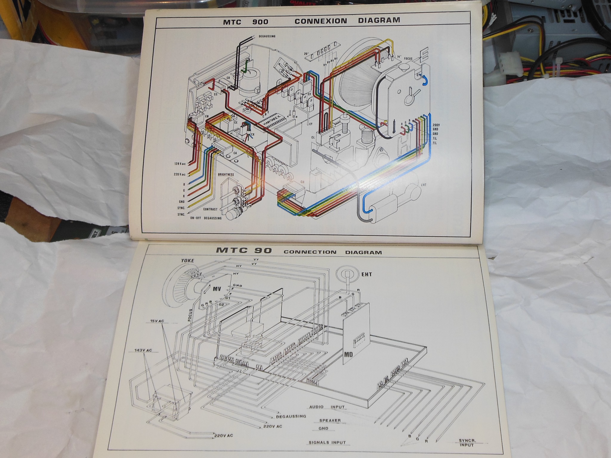
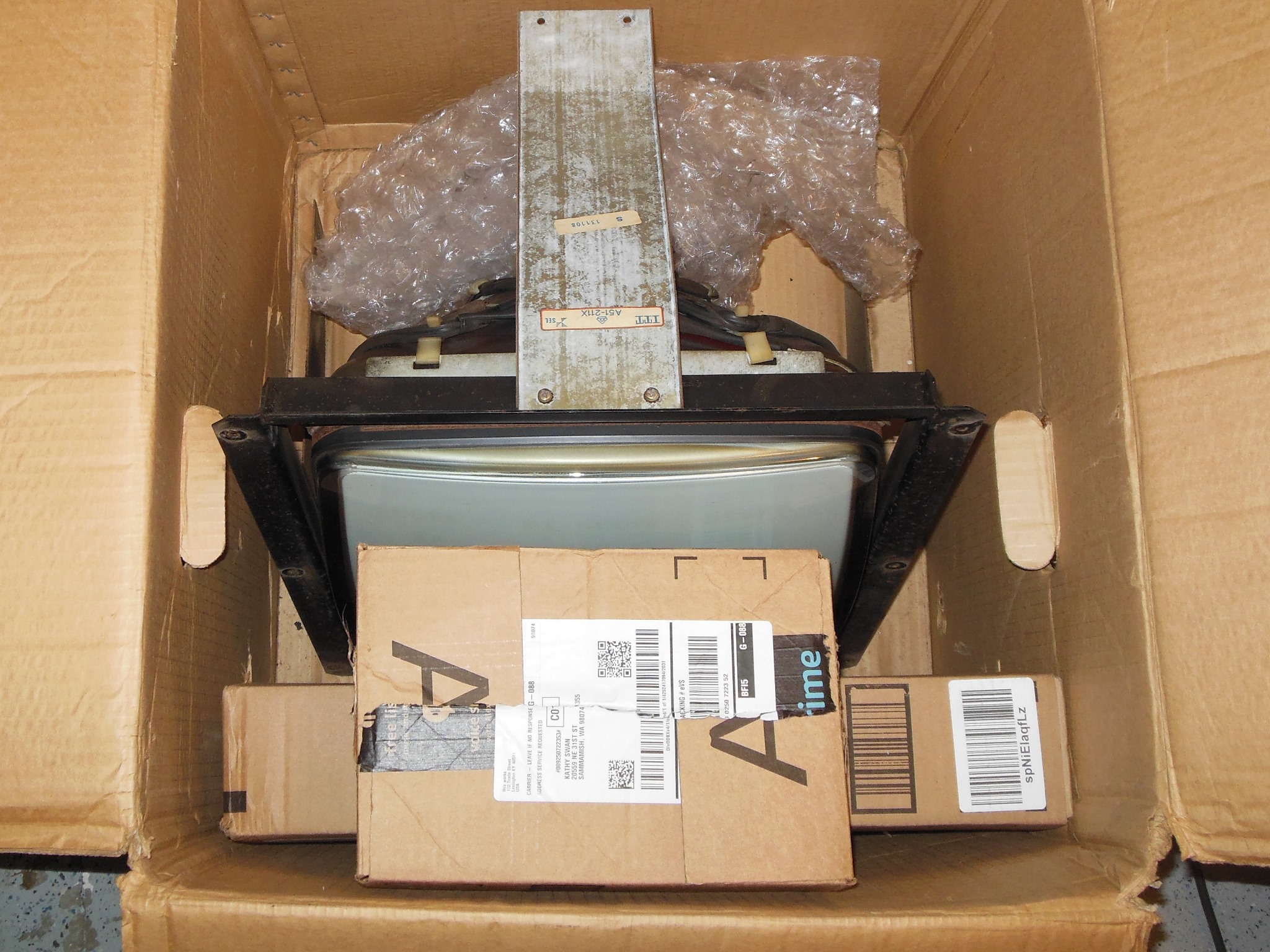
The game had not been in the show for three years due to a poor picture that I'd been holding off looking at until I'd found a spare Hantarex MTC-900 "FB" configured chassis to use to convert from the MTC-90. The one I acquired was in somewhat poor condition, very rusty and the HV cable assembly needed replacing.
|
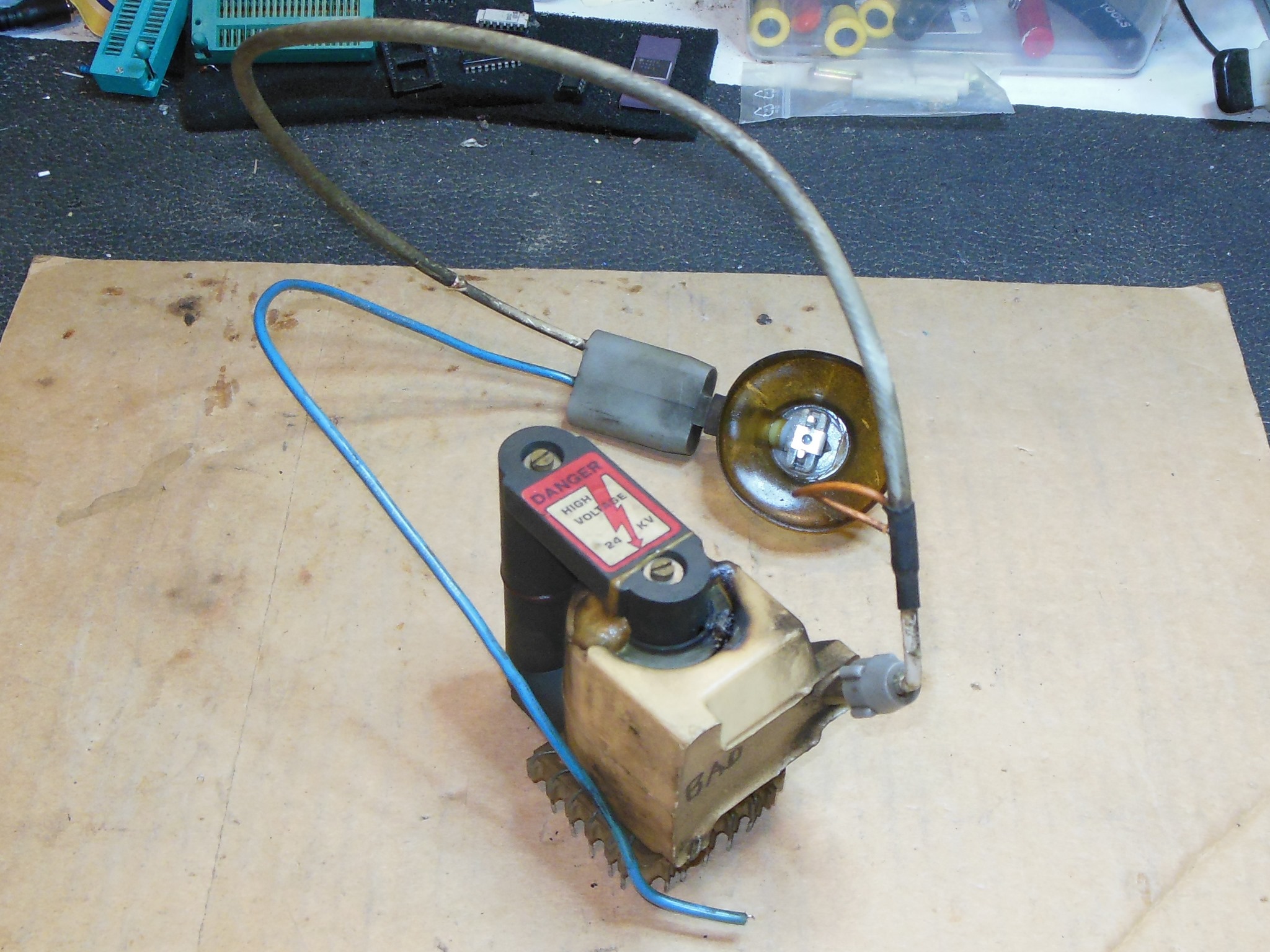
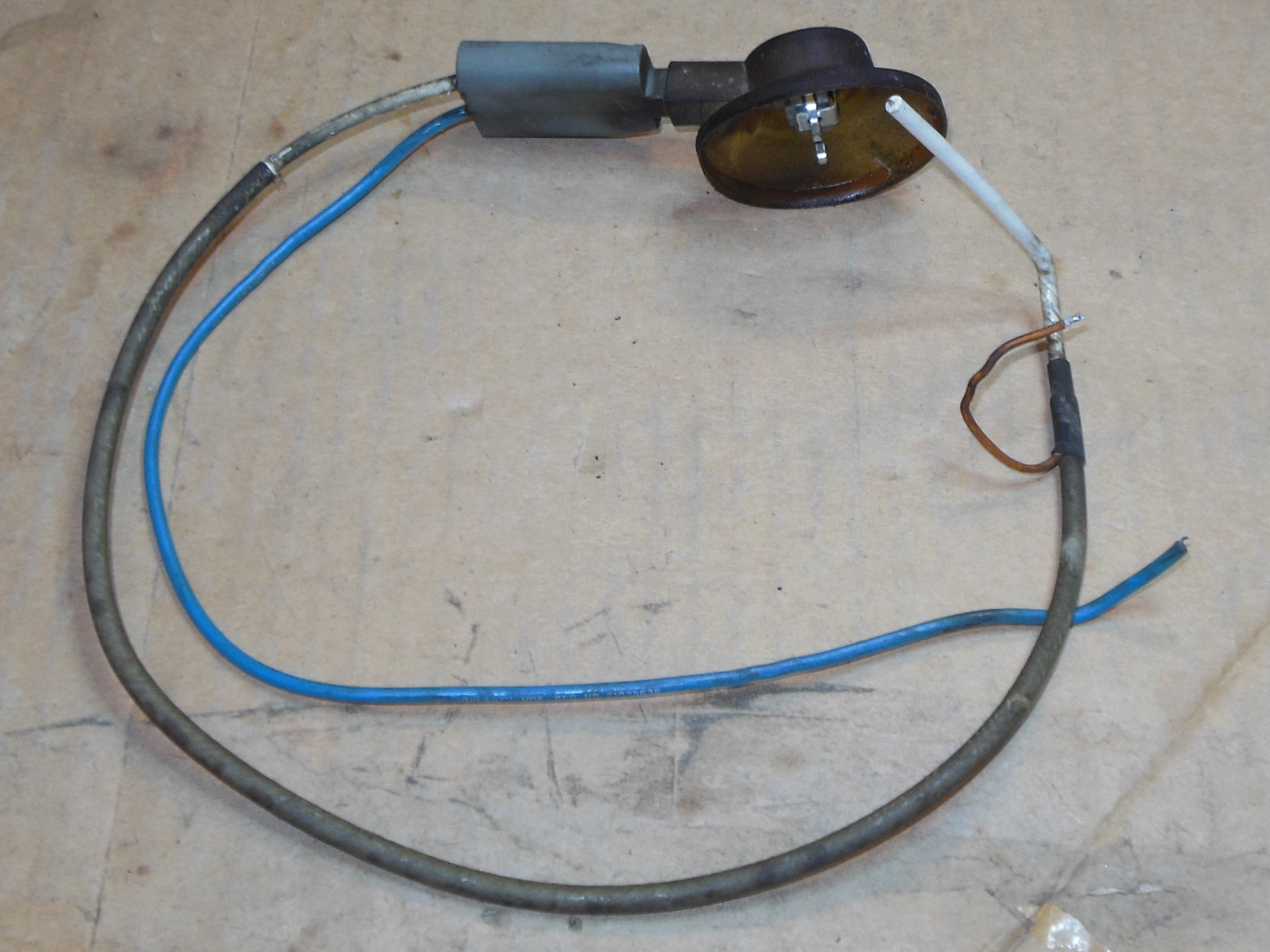
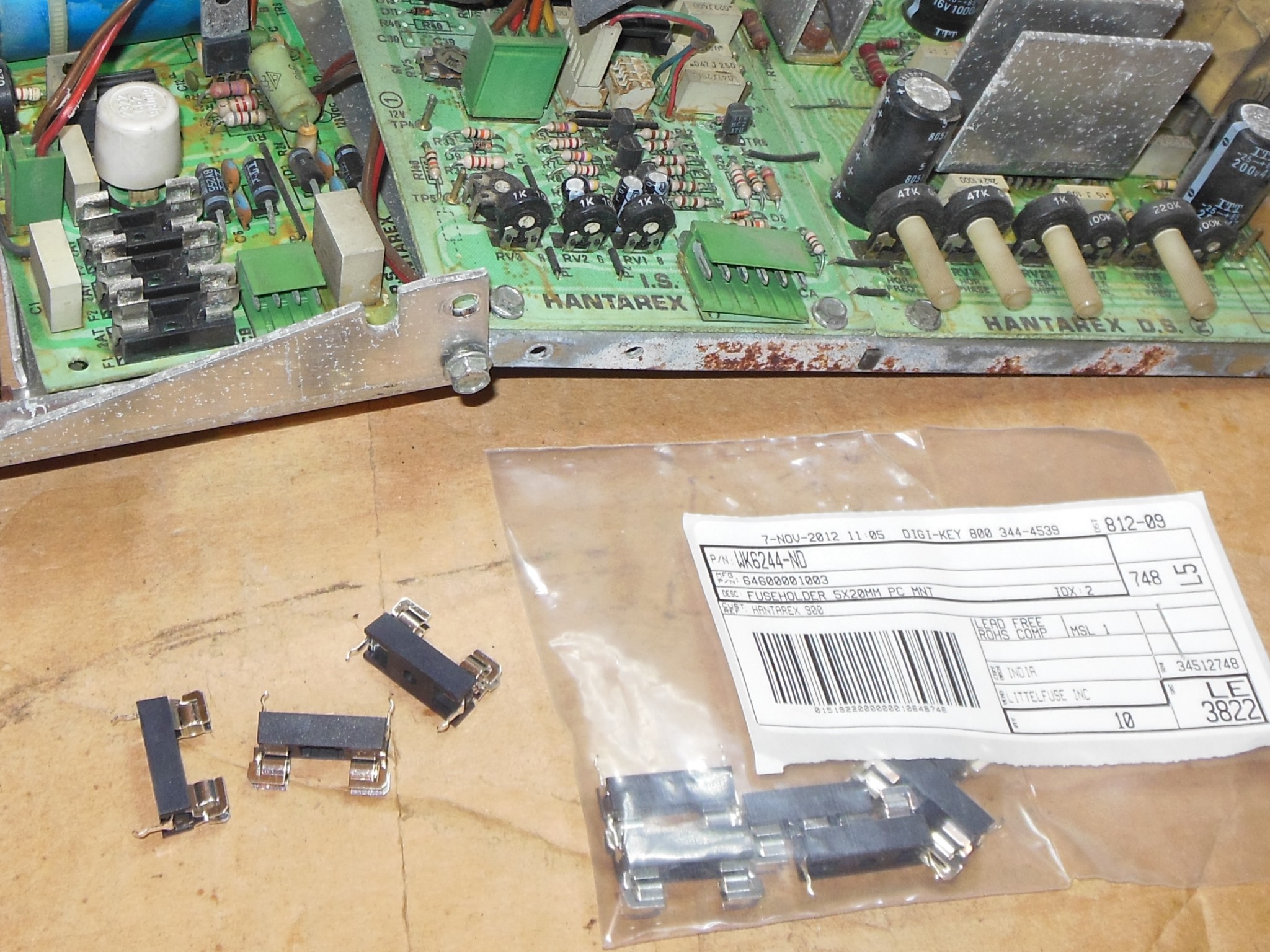
I had one spare blown MTC-900 LOPT from which the HV cable & bleeder assembly was removed for use on this chassis. The fuses on the chassis were also very rusty. The holders were cleaned and new fuses fitted for first power on.

|
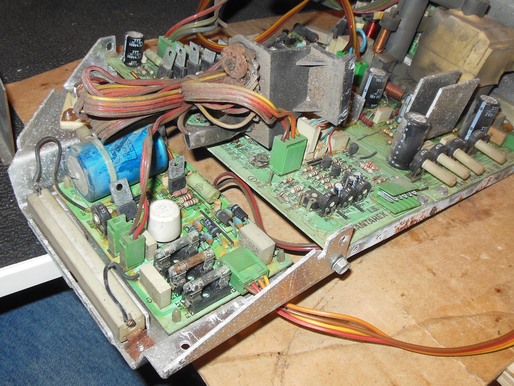
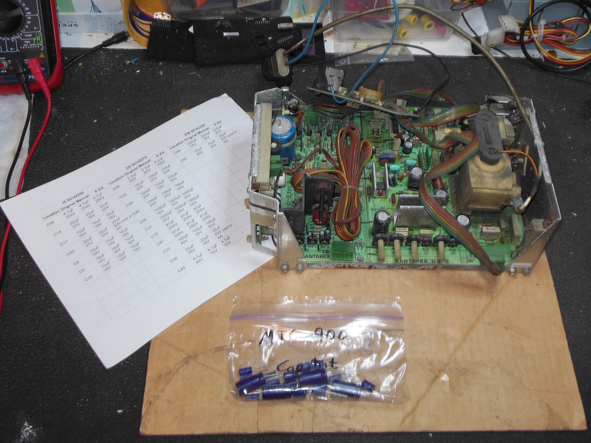
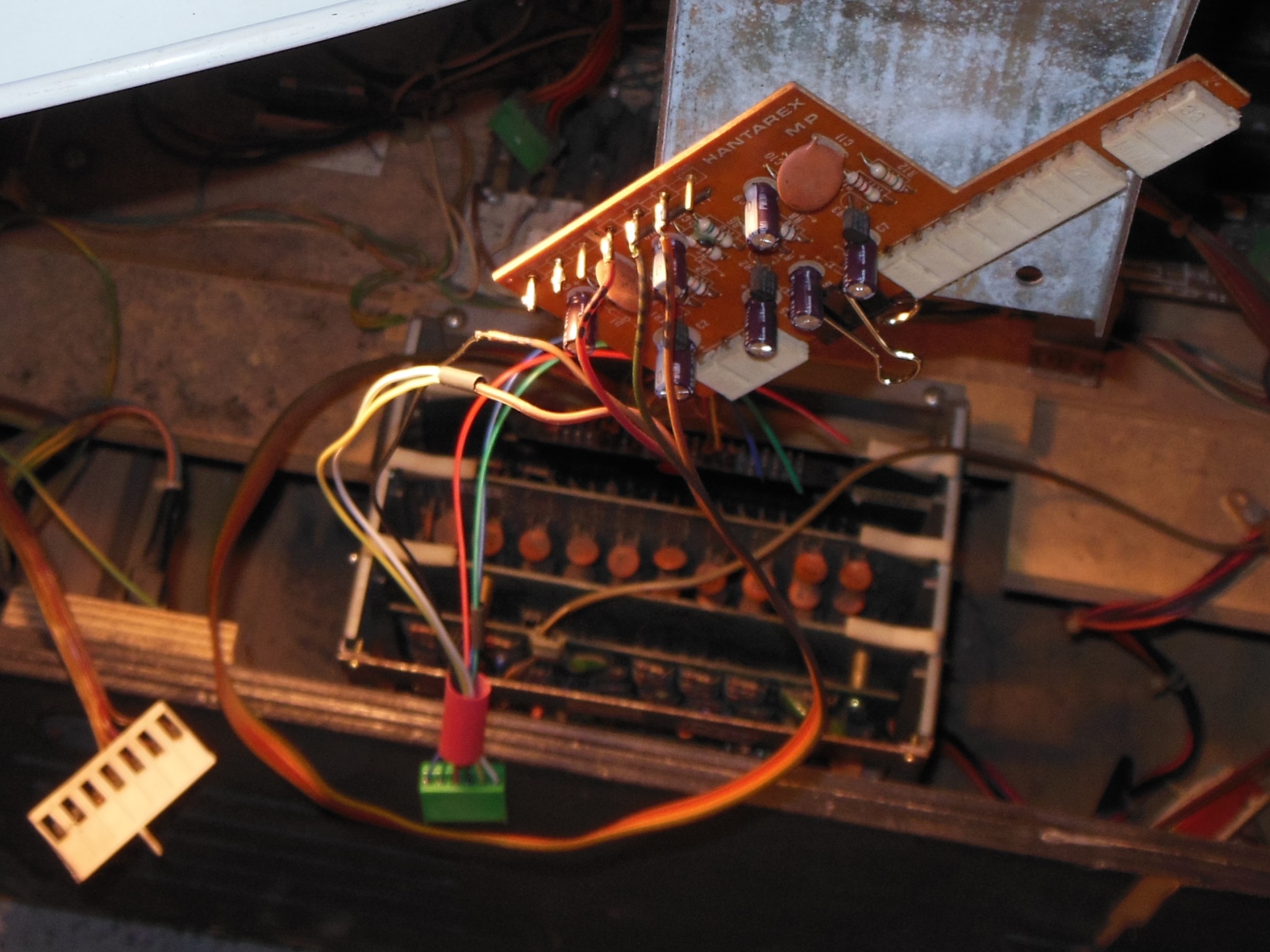
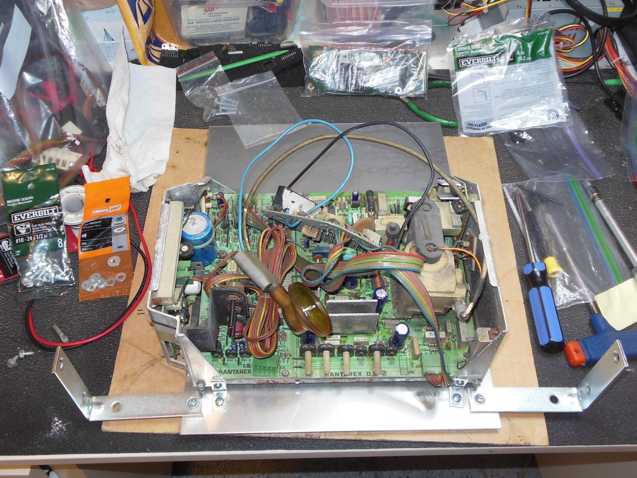
First power on displayed an unstable creased picture along with crackling sounds from the regulation PCB that I suspected was a power regulation issue. The RGB colour drive looked good.
I removed all the transistors from the regulator PCB and tested them for Hfe. TR5 (BF 872) Hfe was 0 and a back-to-back diode test confirmed it was bad. TR6 (BF 871) and TR7 (BC237) all tested OK as did all the diodes. Replacing TR5 fixed the regulation and the on re-test the picture was good. Most of the pots were "dirty" and thus jiggled to clean the tracks.
|
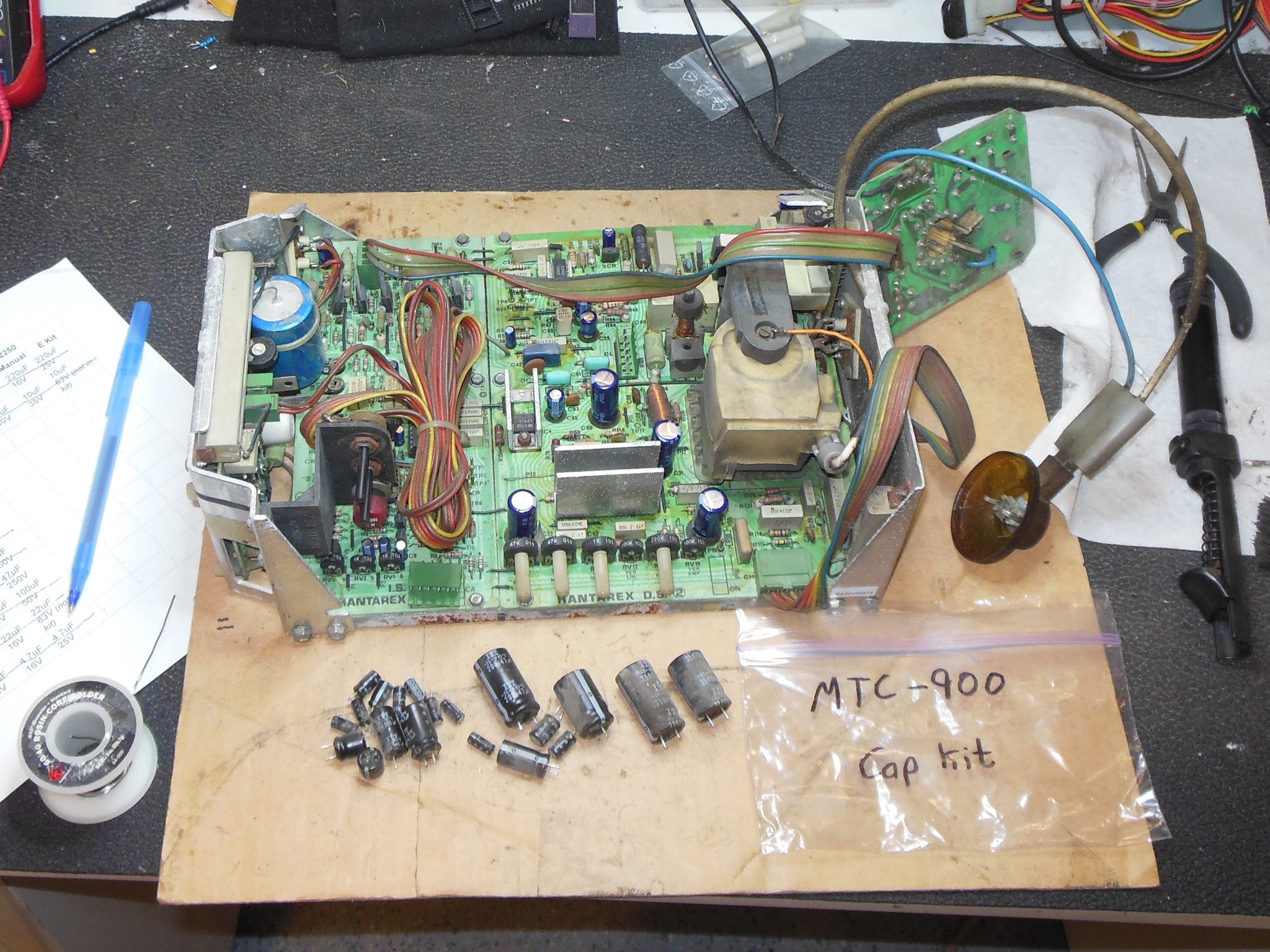
The rusty fuse holders were replaced with new ones and a cap kit fitted.


|
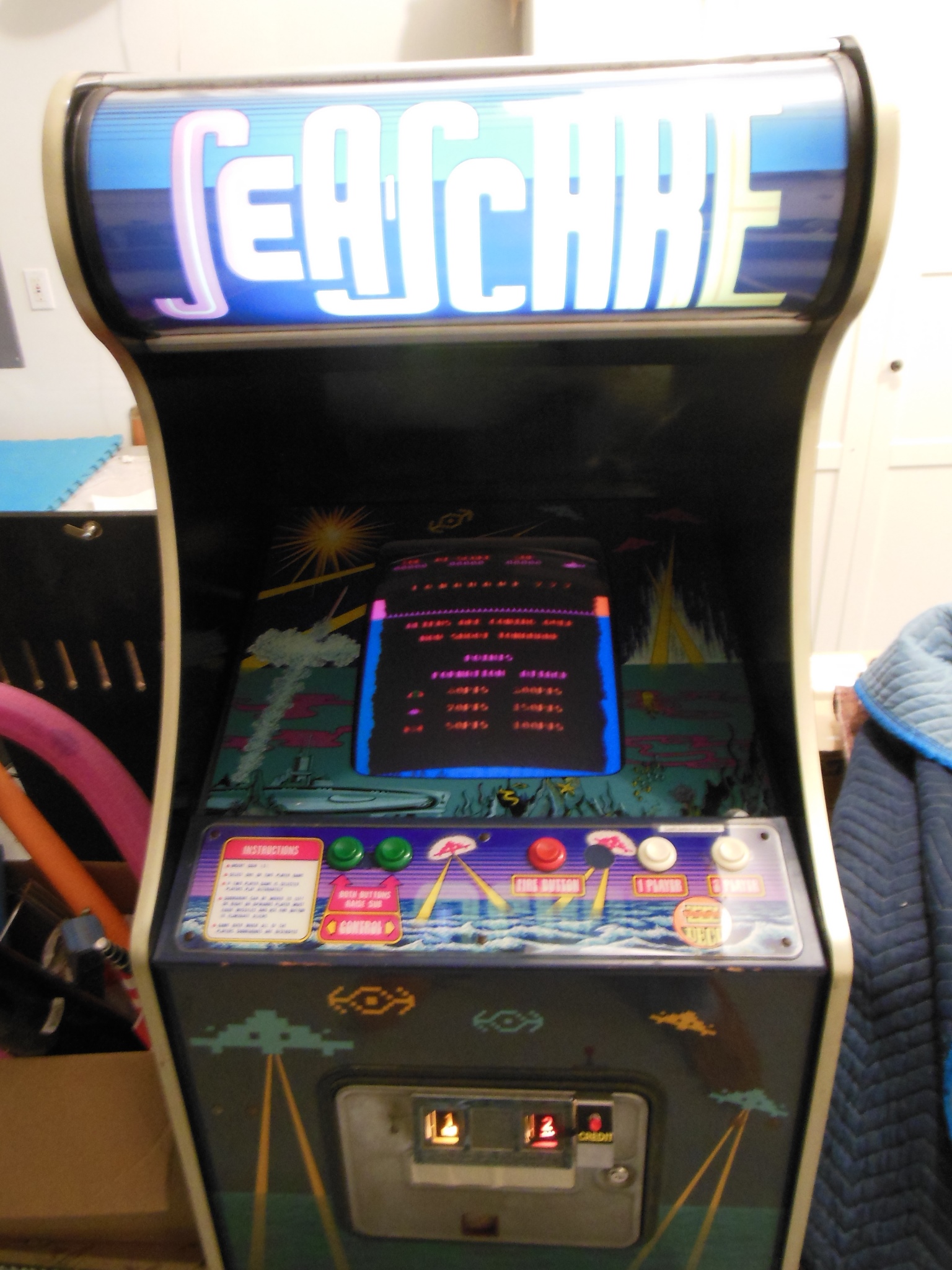
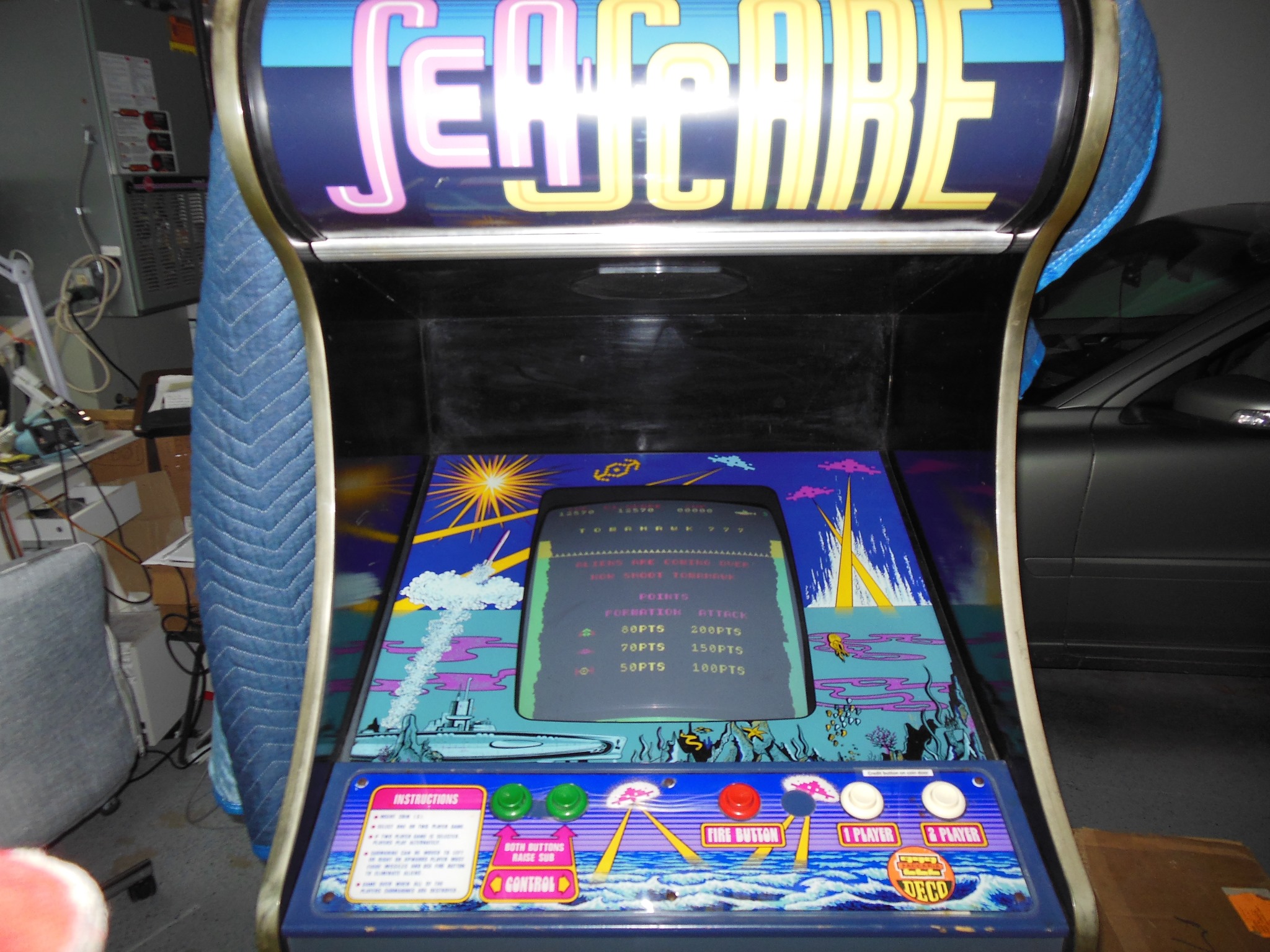
Some additional space had opened up at home so I rented a truck to move my Stern Galaxy pinball, Tehkan Phoenix, US Billiards Quasar and Zaccaria Sea Scare home.
|
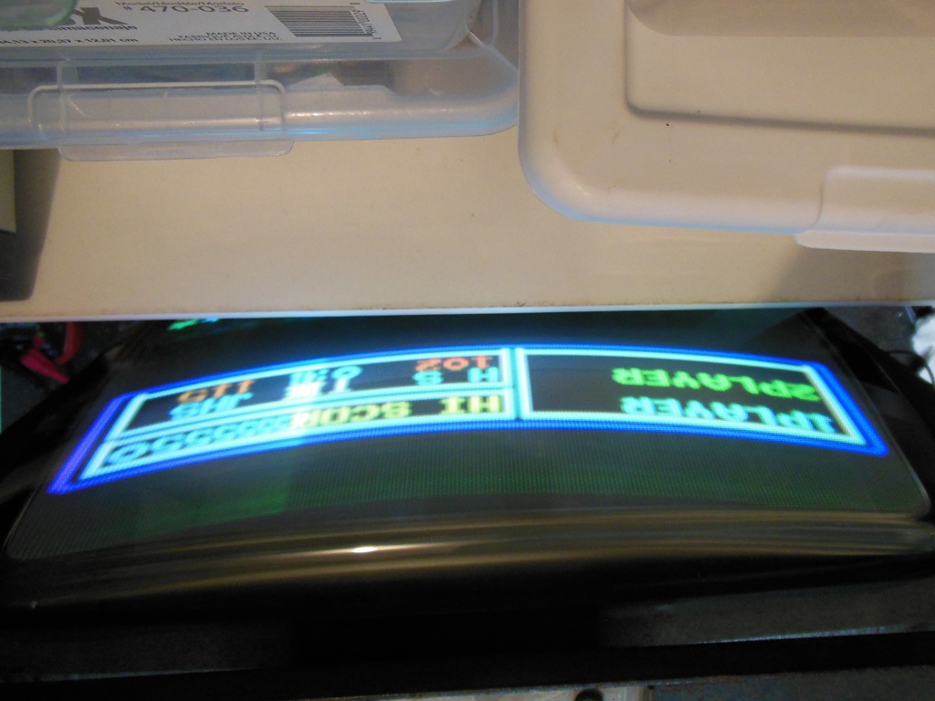
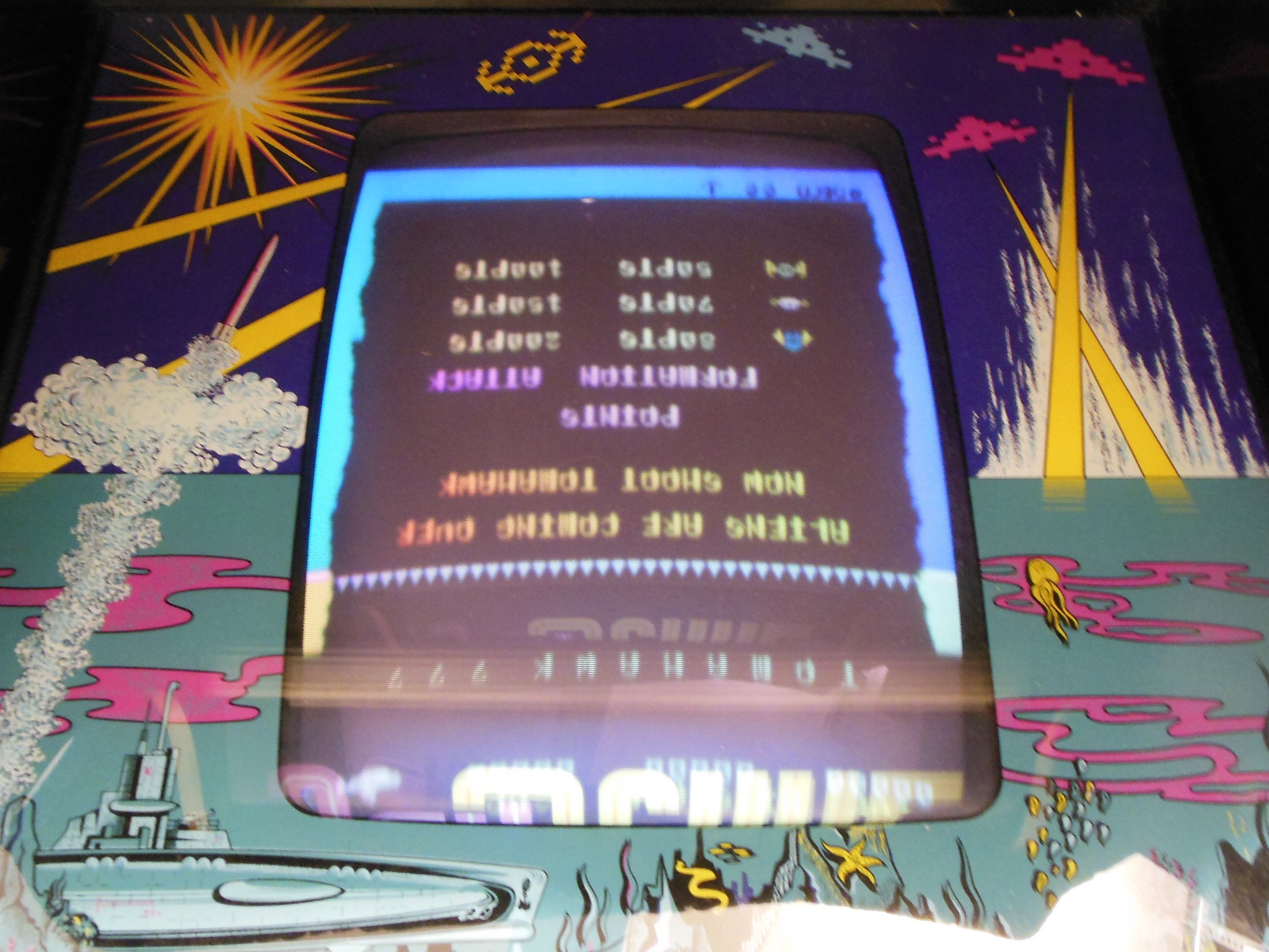
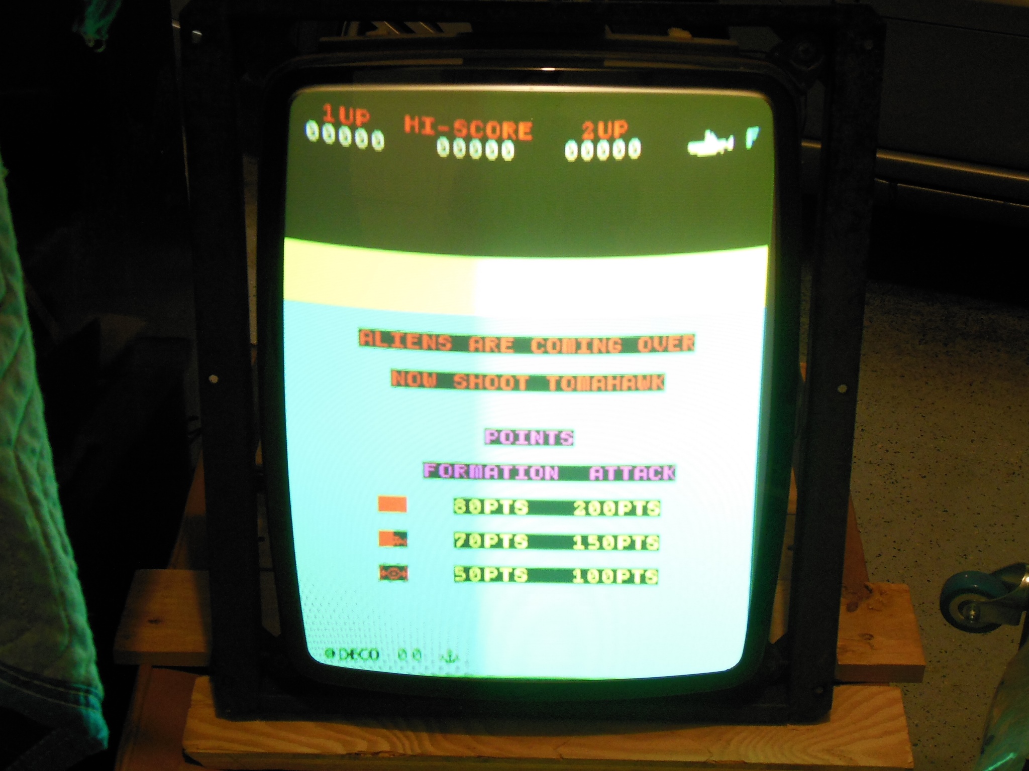
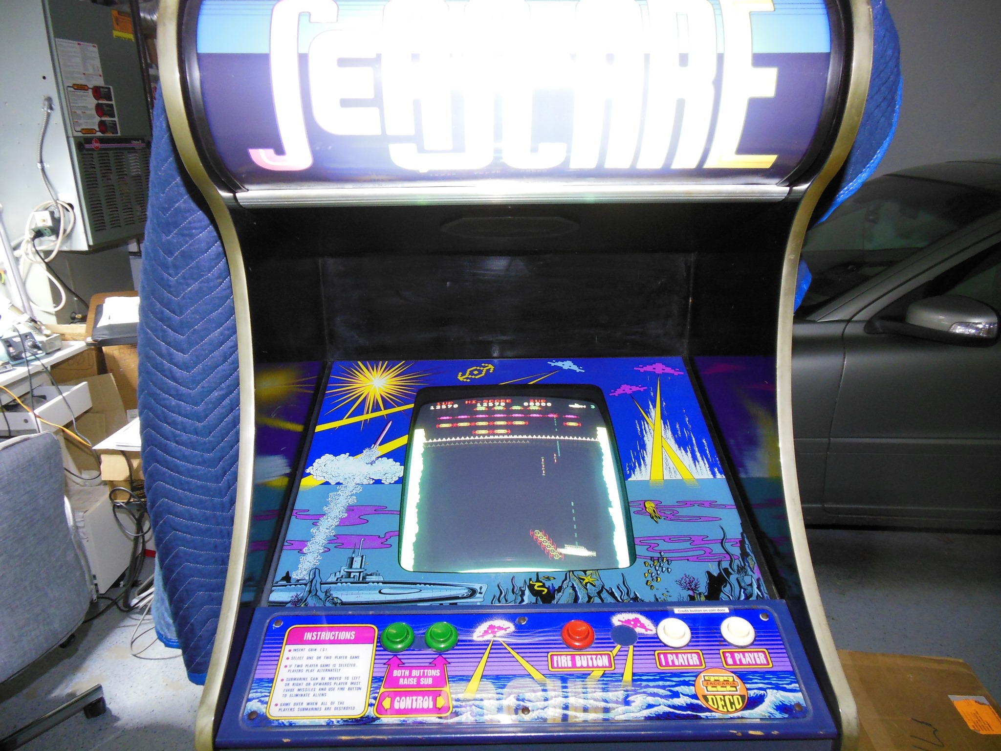
Despite three years having passed since it was last powered on the game came up working OK. The picture was still dim with poor focus and slight bleeding.
|
The photo makes the picture look much brighter than it really is. I wasn't able to get anything better with the MTC-90 chassis and decided to go ahead with the MTC-900 conversion for better long term maintenance.

|
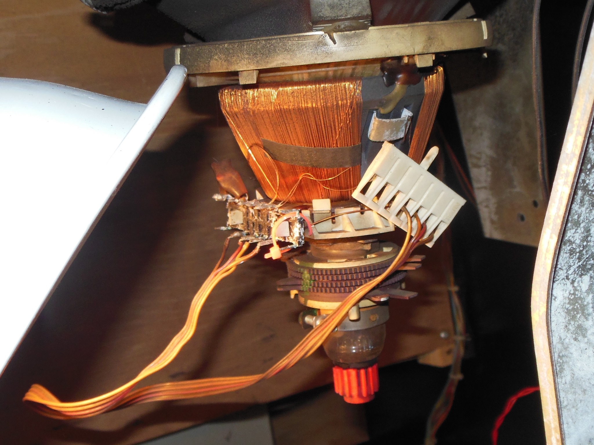
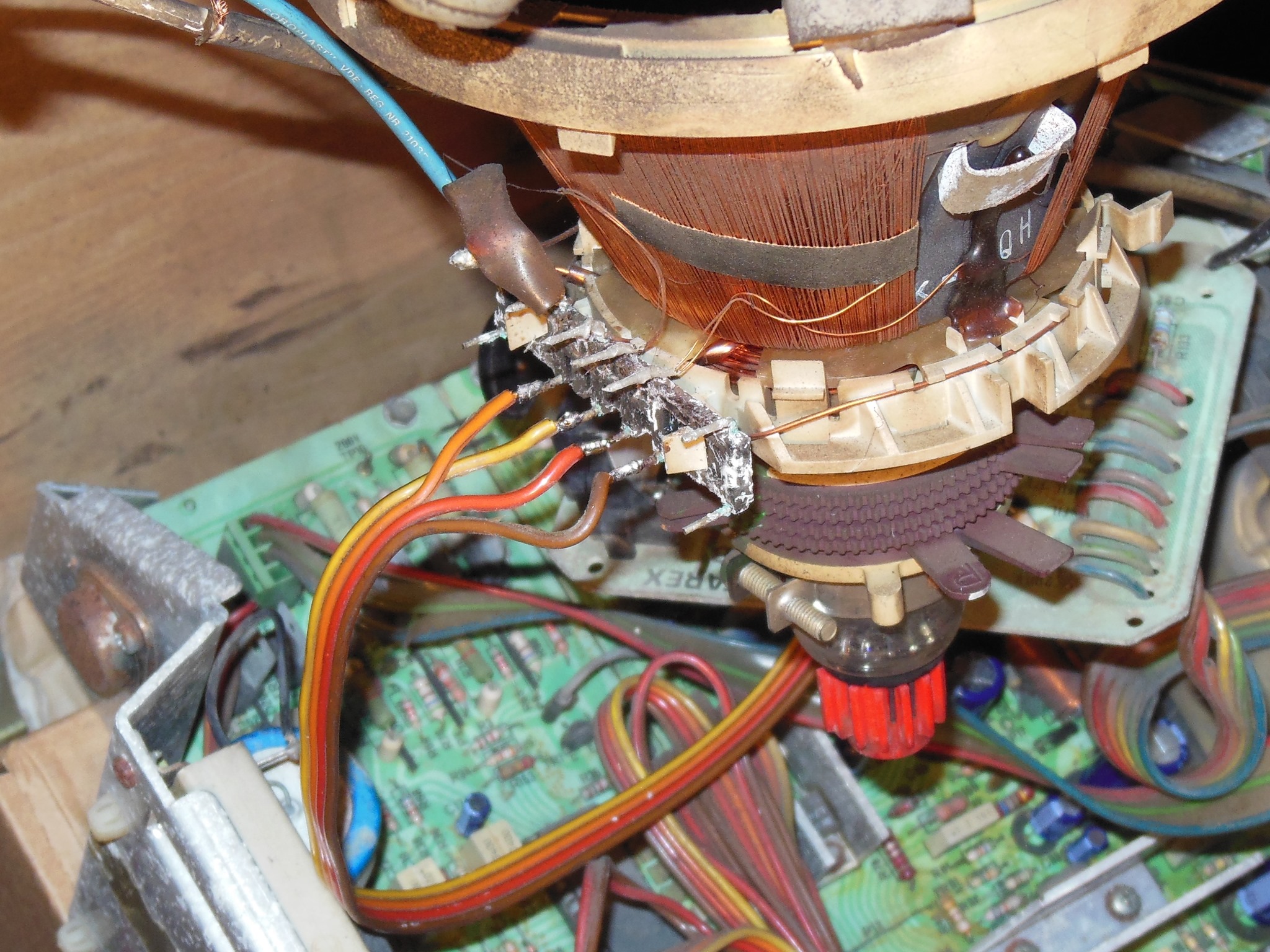
The first step of the MTC-900 conversion was to replace the degauss coil connector using the old chassis frame as "helping hands" before it was removed.
|
The MTC-90 chassis was removed and packed away. The MTC-90 makes a good parts chassis as it shares many components with the later MTC-900 series chassis, most notably the power transistors and coils.
|
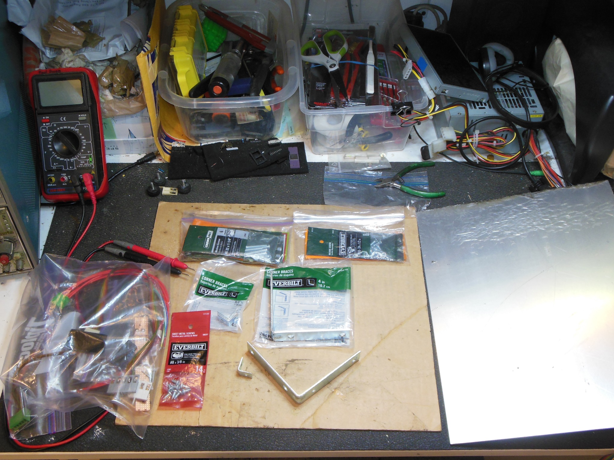
Knowing that it was going to be a while before the last MTC-90 was converted I'd already built the power & video input cable assembles and the voltage drop board when the other two were done so I wouldn't have to figure all those things out again once forgotten. All the brackets and screws were also already in stock and the metal base plate hole locations had already been marked. The change that needed care was fitting the MTC-900 yoke connector in place of the MTC-90 one using the manuals for reference.
|
The voltage drop board was fitted to the 220V & 143V AC outputs from the transformer block and the MTC-90 video input board removed & replaced with the pre-assembled MTC-900 video input connector.
First power on was very much an anti-climax - the picture was still poor and dim :( This chassis was clear and bright on the bench test CRT so the lack of any significant improvement in the cabinet from the MTC-90 chassis suggested that the Sea Scare CRT was likely bad :(
|
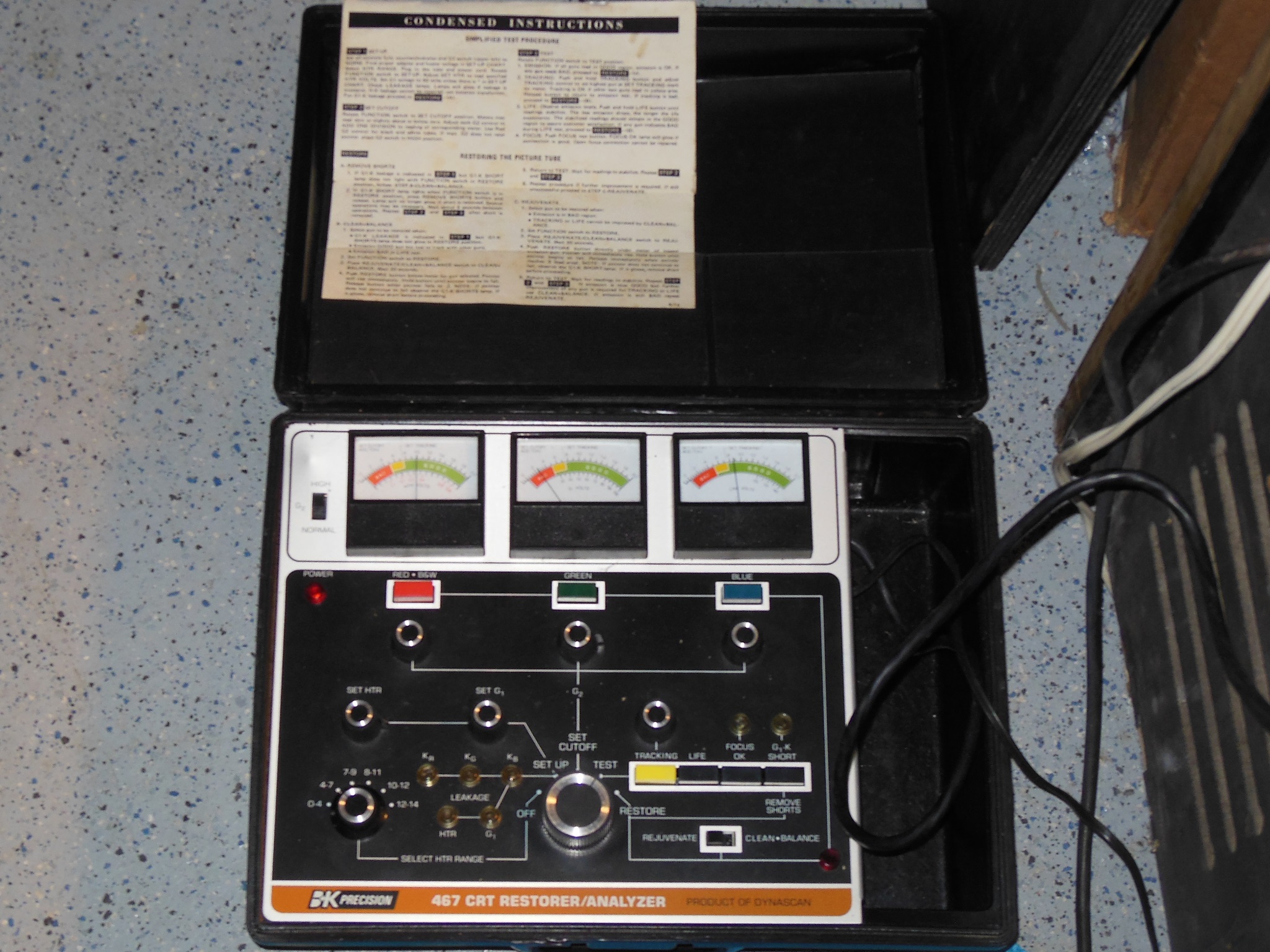
I'd already had the Sea Scare CRT on the rejuvenator before without much improvement. Initial testing found all three guns low. After a few passes through rejuvenation, red & blue were just in the good zone but green remained in the poor zone. No further rejuvenation was improving the readings.
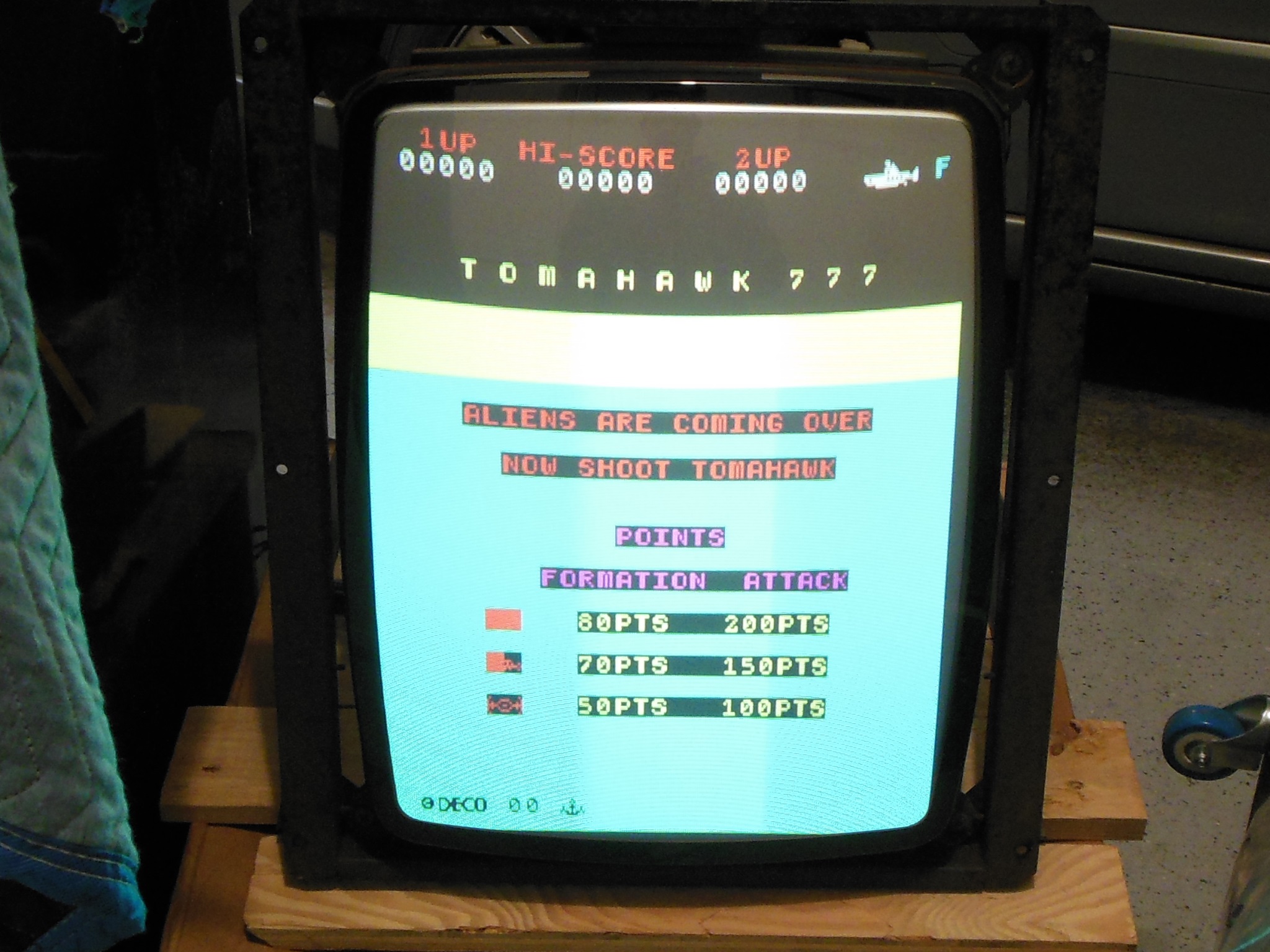
The upside down picture was straight forward to correct by swapping the horizontal & vertical yoke wires. On second power-on the picture was orientated correctly and the picture quality was slightly brighter but still poor :(
|
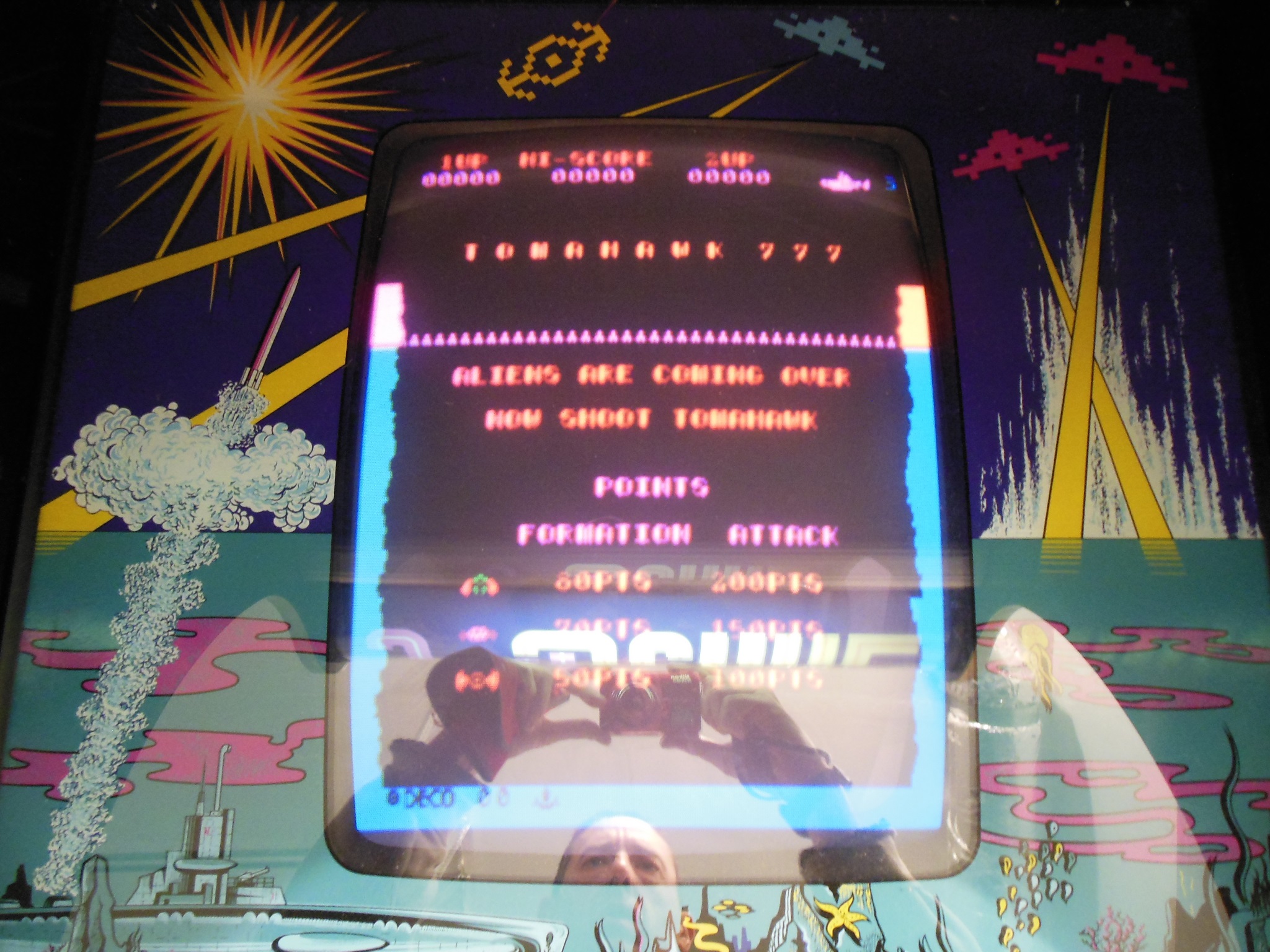
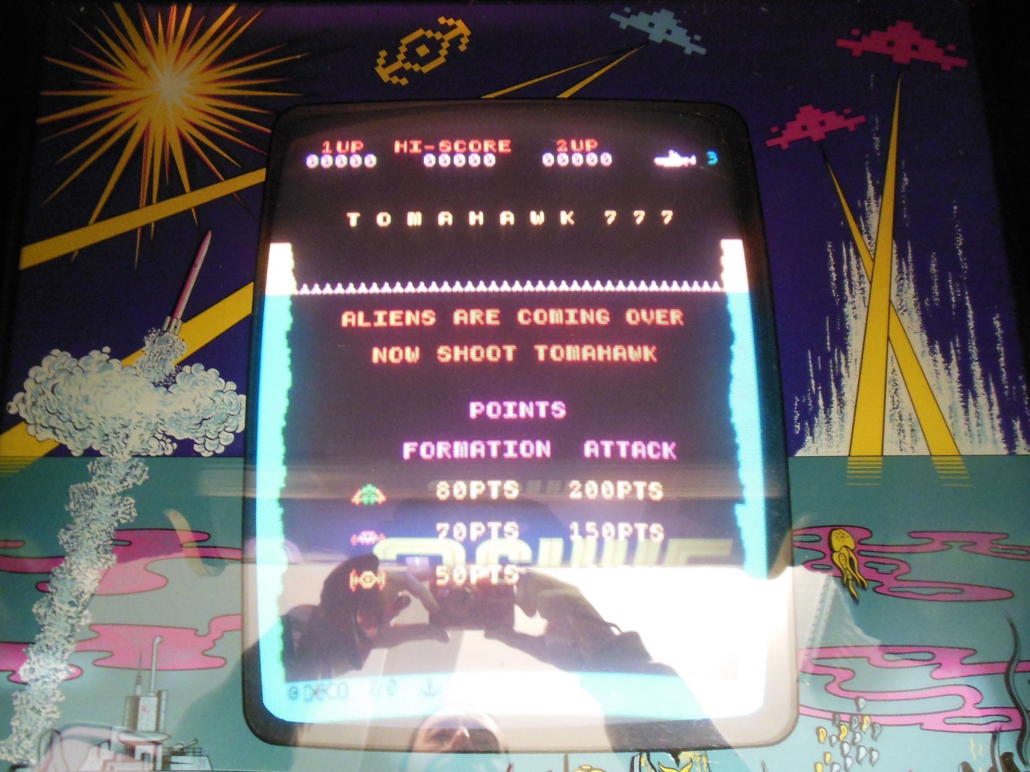
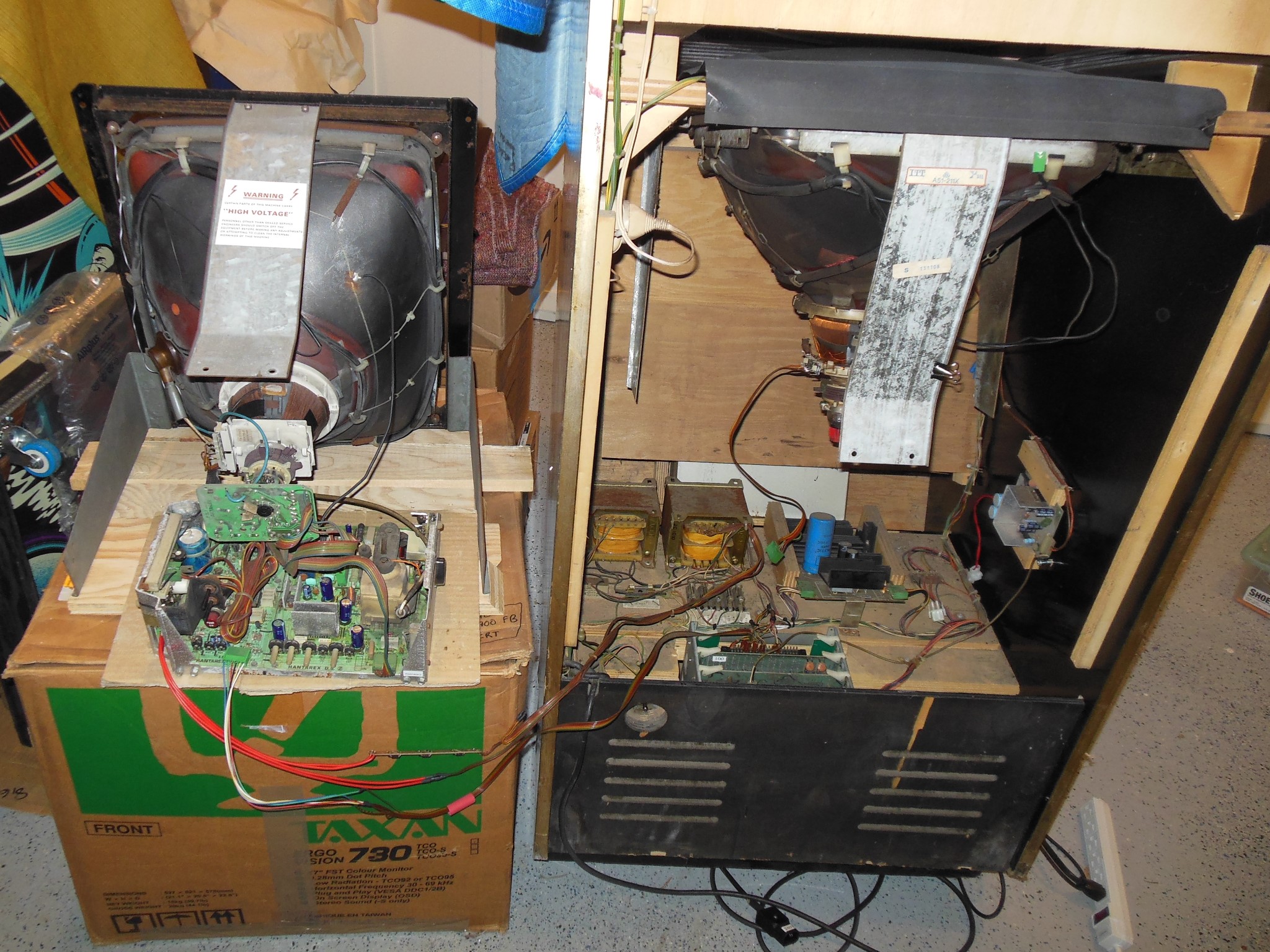
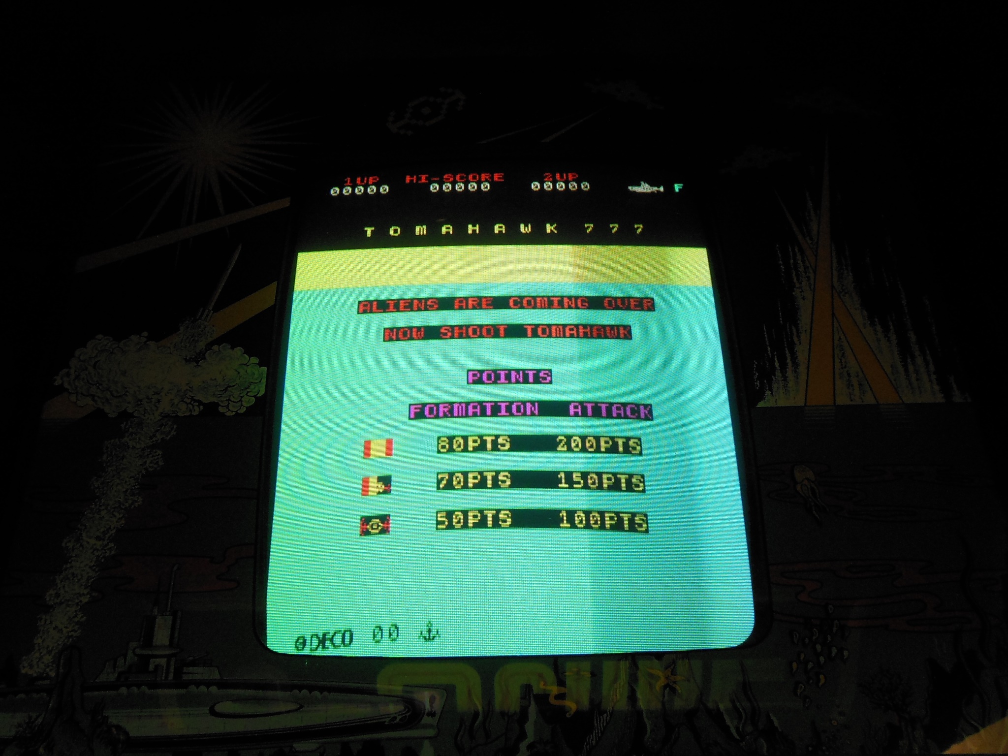
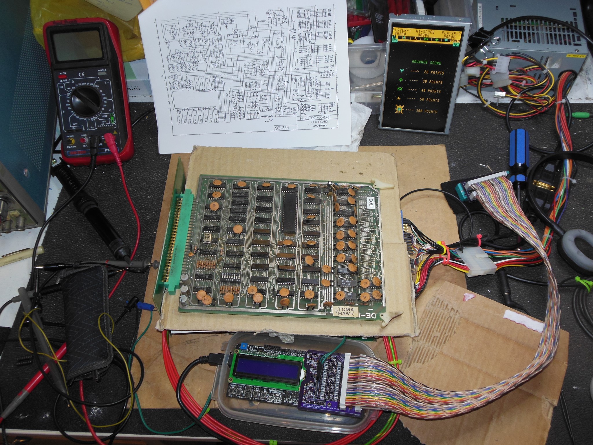
The final step in the investigation was to put the chassis back on the bench test CRT run from the cabinet power supply & Tomahawk 777 video. As expected the picture was bright & crisp. A couple of small tweaks produced an excellent picture confirming that the Sea Scare CRT was the problem. Since the bench test CRT was from an MTC-90 monitor itself I decided to swap my good bench test CRT into the cabinet and use the poor Sea Scare CRT for bench testing.
The game PCB had also developed fault.

|
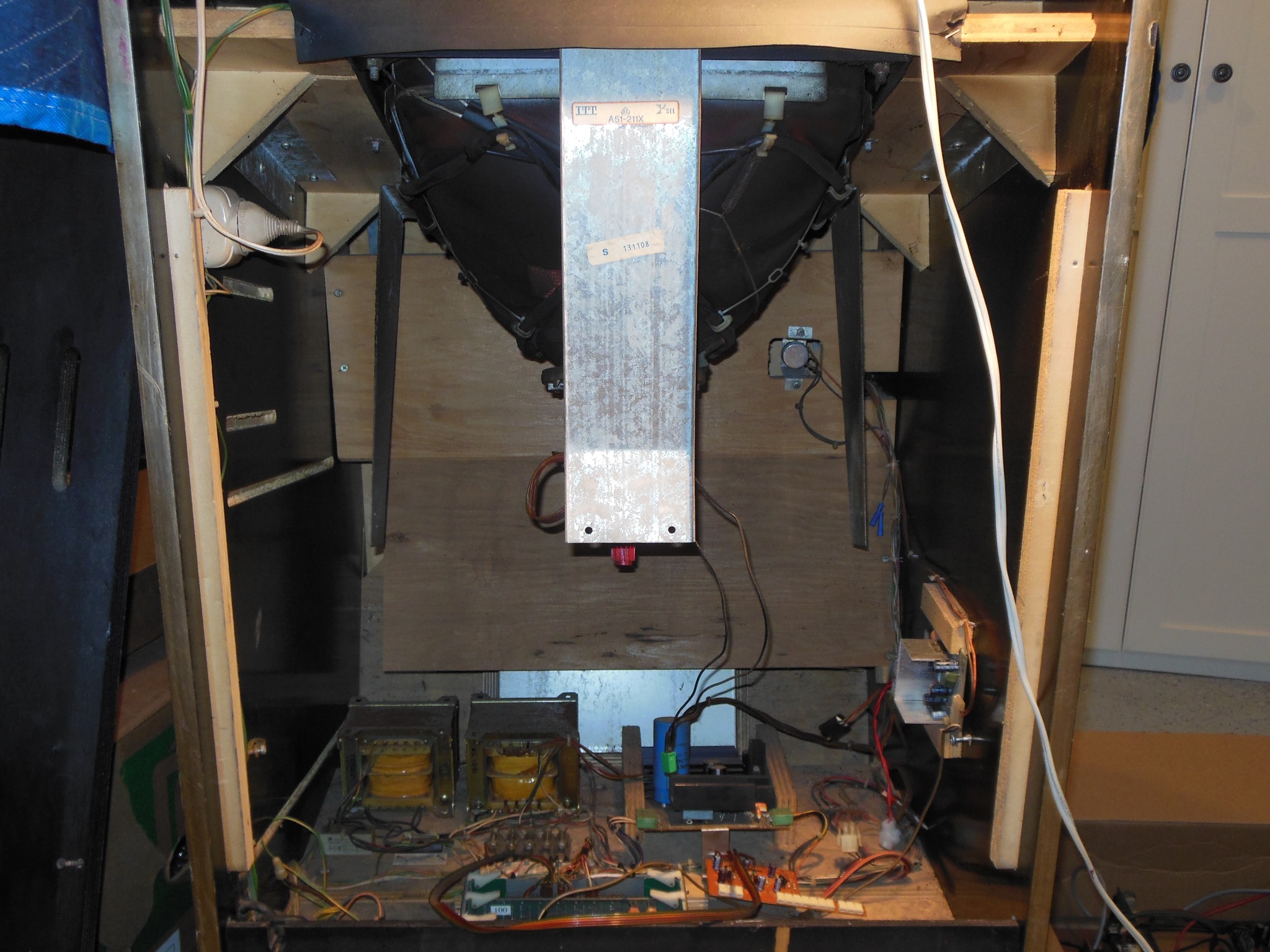
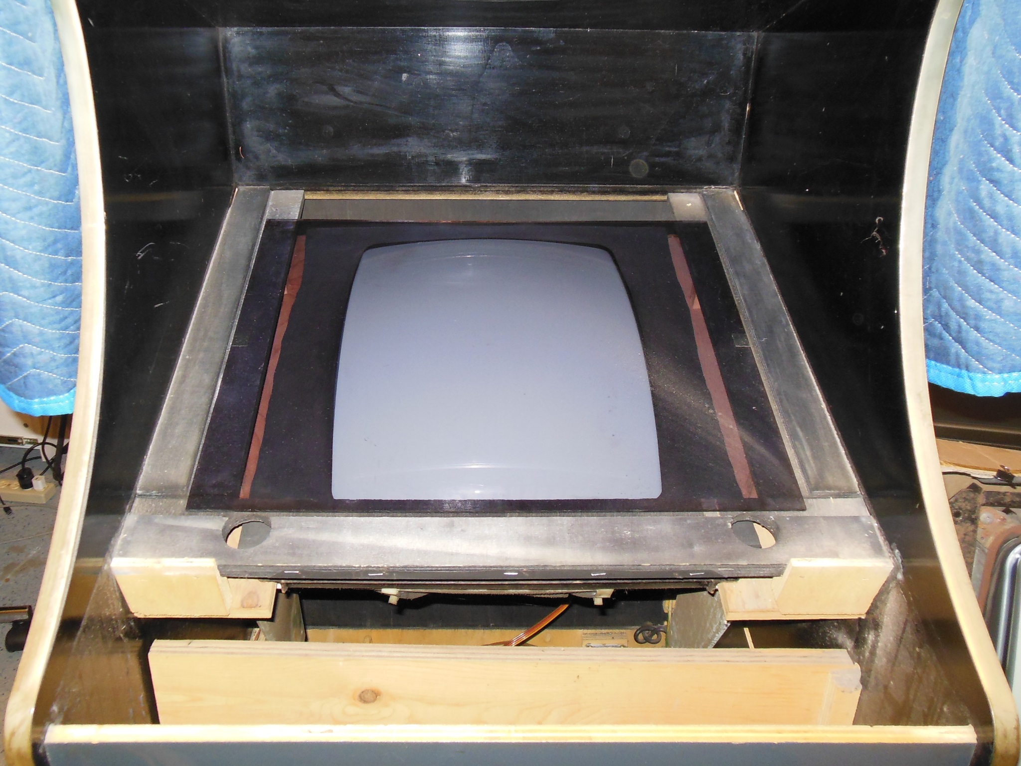
To remove the monitor CRT frame necessitated the removal of the control panel, monitor glass, tint glass & cardboard surround. Six screws held the frame at the front and the two screws holding the back wall also needed to be undone to allow the monitor CRT frame to slide out of the back. The good test bench CRT frame was then slid back into place and everything reassembled.
|
The spare MTC-90 CRT frame was packed away for future bench test & repair.

|
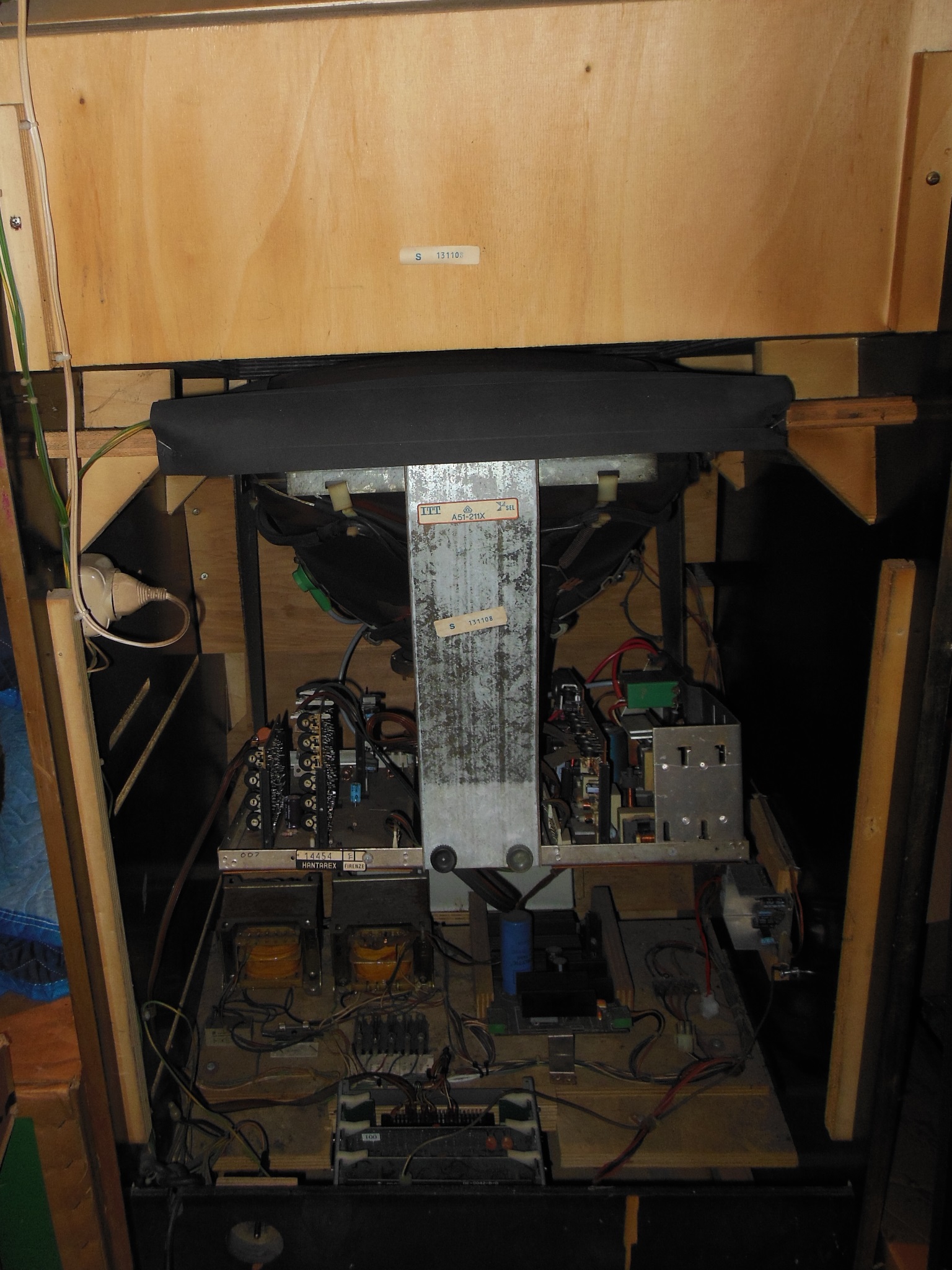
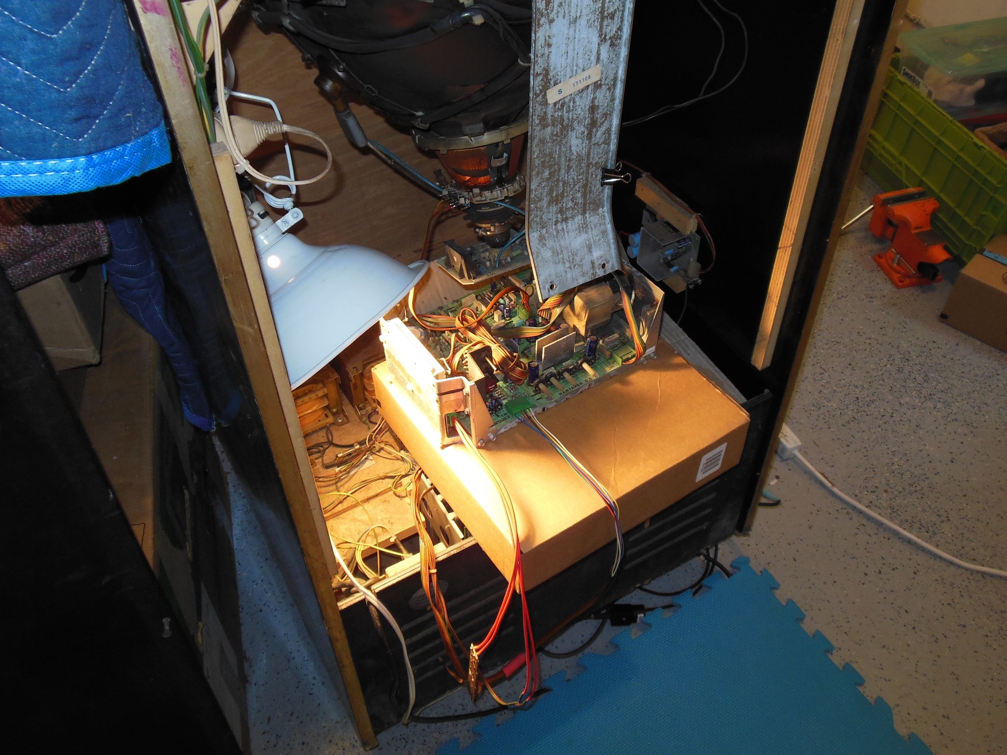
The MTC-900 chassis was mounted onto the plate along with the two side brackets to secure it to the MTC-90 frame. The assembled plate was then installed onto the MTC-90 frame, connected up and the cabling secured. First power on didn't encounter any issues and a few geometry tweaks finalized the picture quality.
|
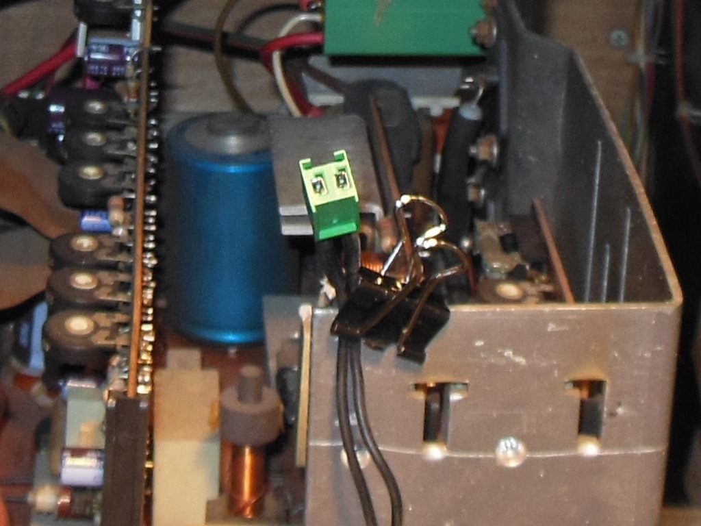
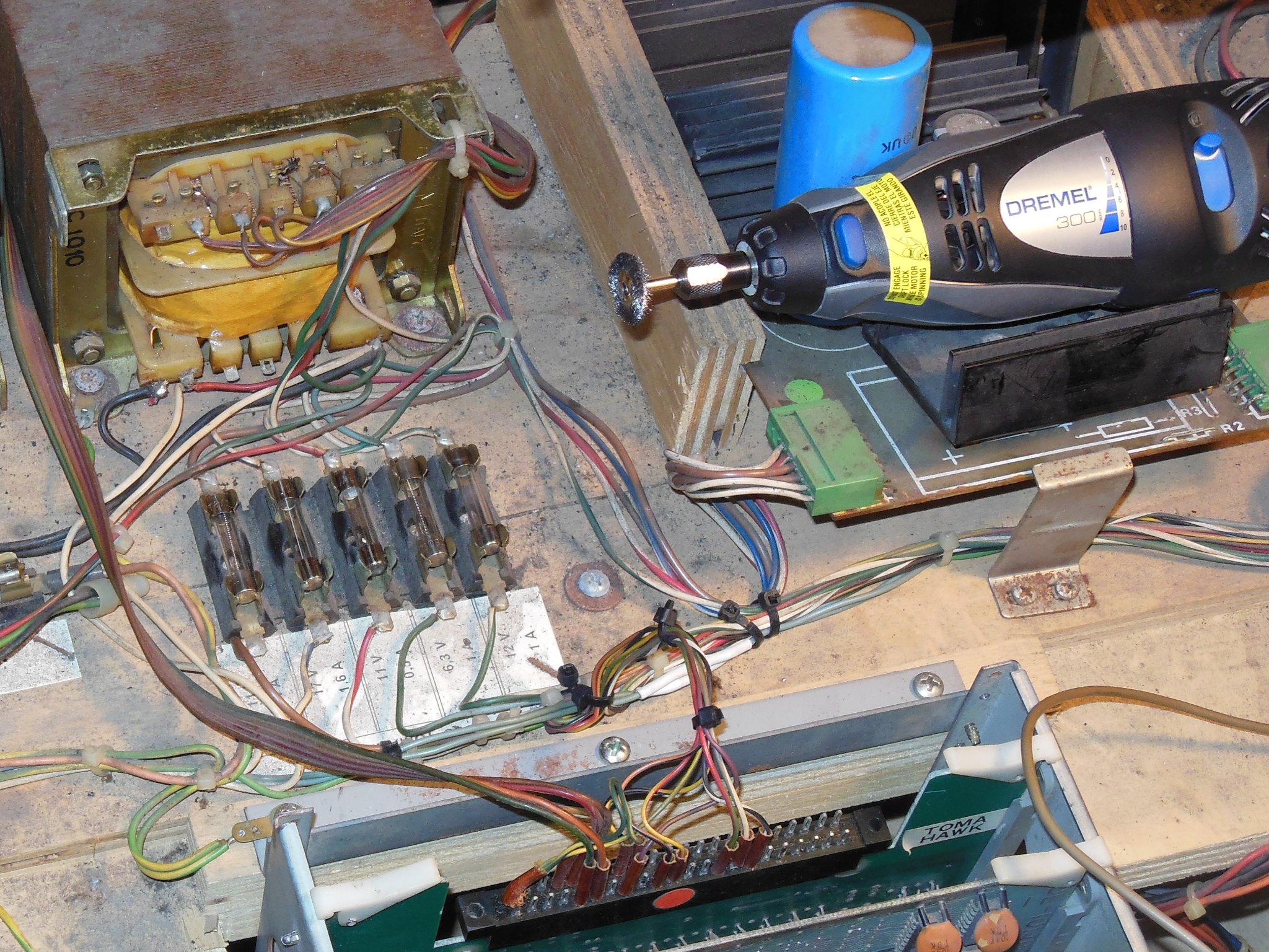
A cursory check of the fuses found them a little warm so I cleaned them up with a wire brush Dremel.

|
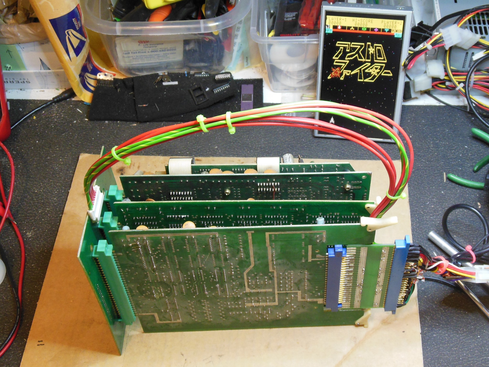
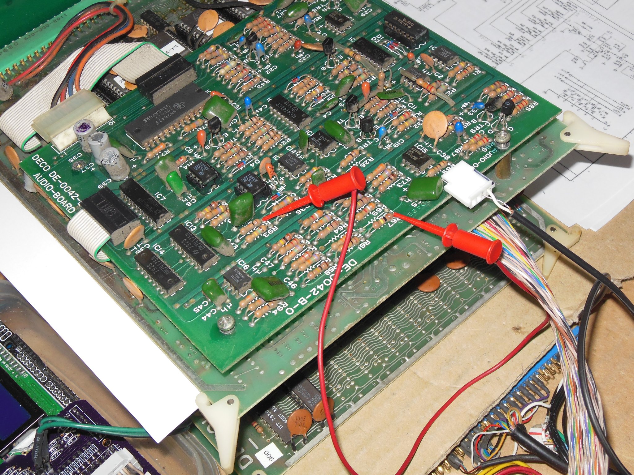
Since the game board set consists of three PCB's mounted in a card cage my test bench setup was based on a complete working Astro Fighter board set and an open edge connector PCB without cage. This allowed any of the three Tomahawk 777 PCB's to be tested individually on the bench. Testing the Tomahawk 777 ROM, RAM & audio PCB on the bench confirmed that it was the problem.


|
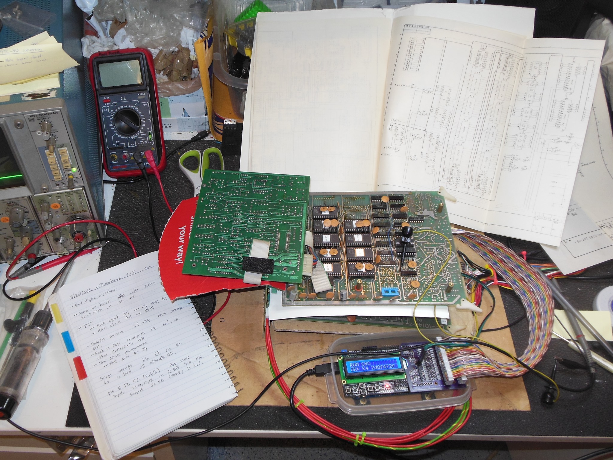
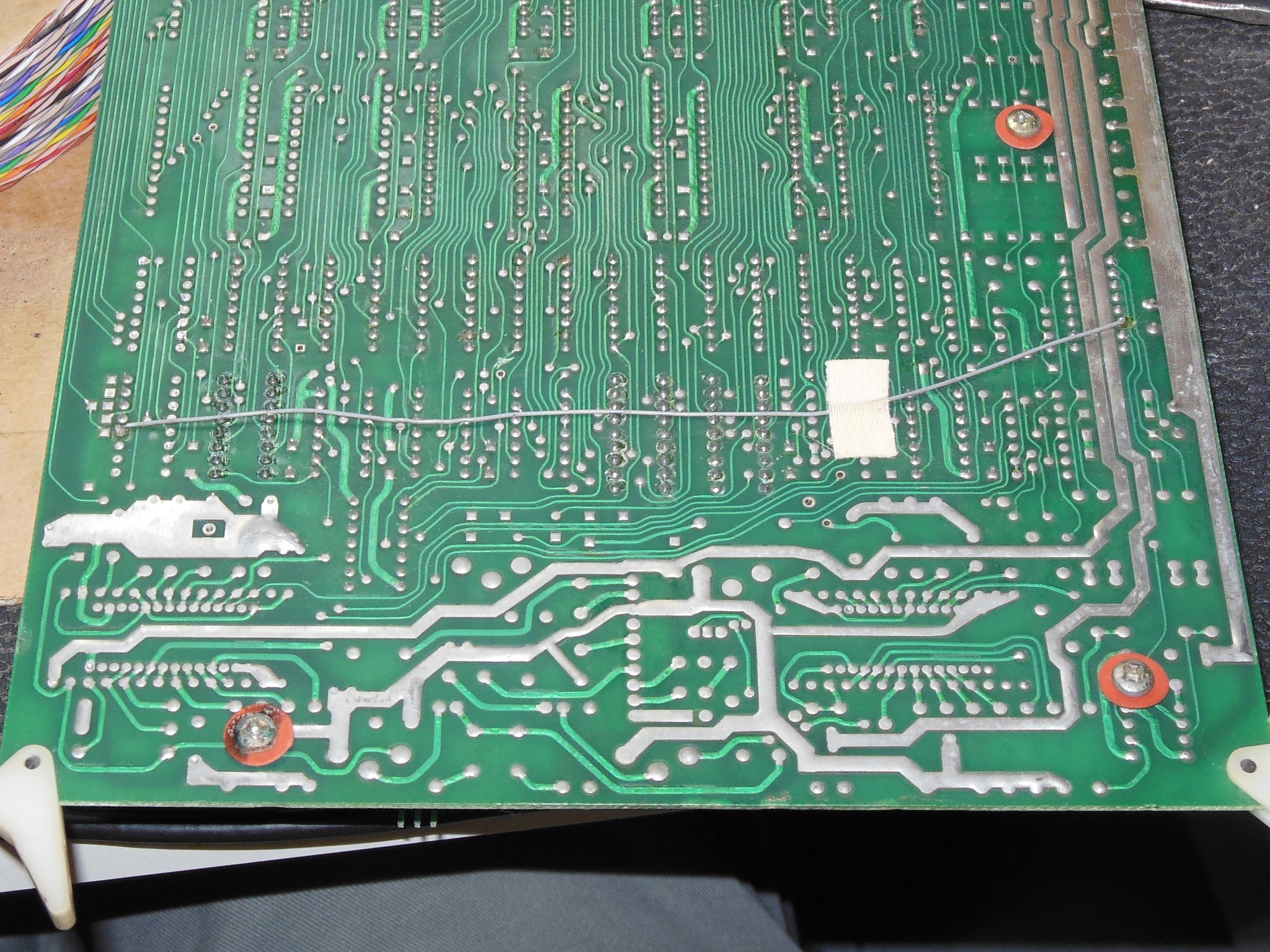
Testing with the Arduino ICT connected through the CPU board flagged "E: K4 4401 B1 FF" on the "ROM Check All test", suggesting EPROM K4 (2708) was bad. The DataIO UniSite verified EPROM K4 as good but I still programmed a replacement 2708 for it in case it was marginal on the PCB. However, the ICT still flagged the new K4 EPROM as bad. Looking on the scope during K4 testing found the logic low level on K4 ~CS signal bad. All the remaining ~CS signals on the other EPROMs looked OK. Working back to IC 2B (7442) found the signal output bad but the inputs on pins 15, 14, 13, 12 all looked OK. I suspected IC 2B was bad and replacing it fixed the ICT ROM test and the game ran OK back in the cabinet.

|
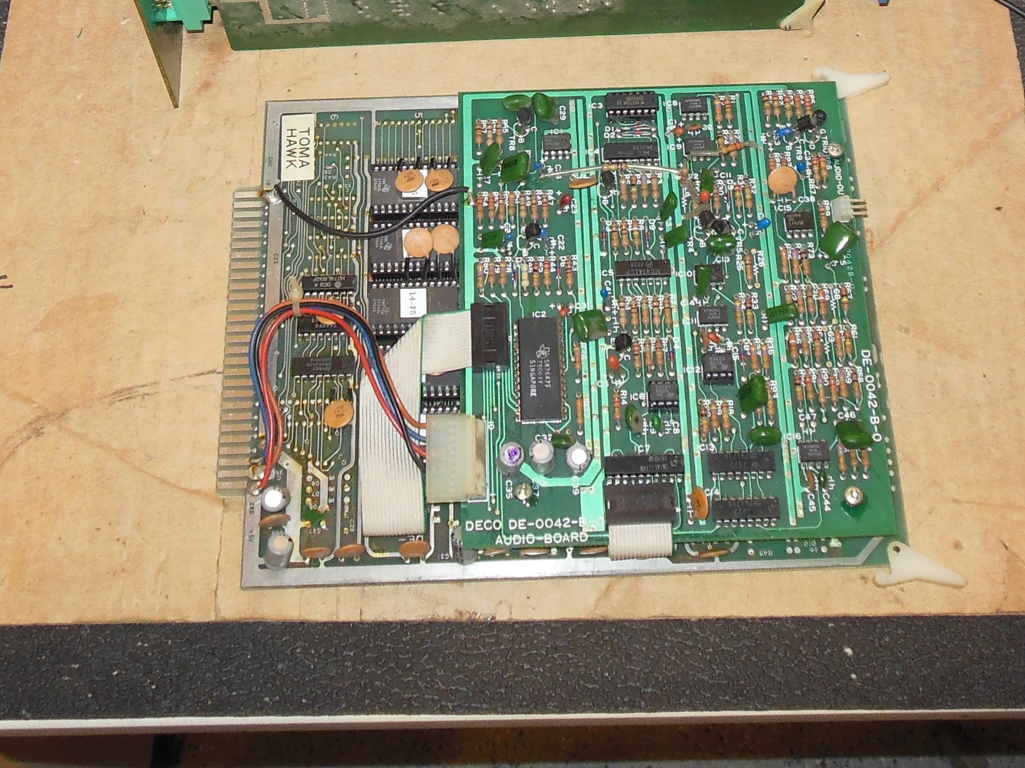
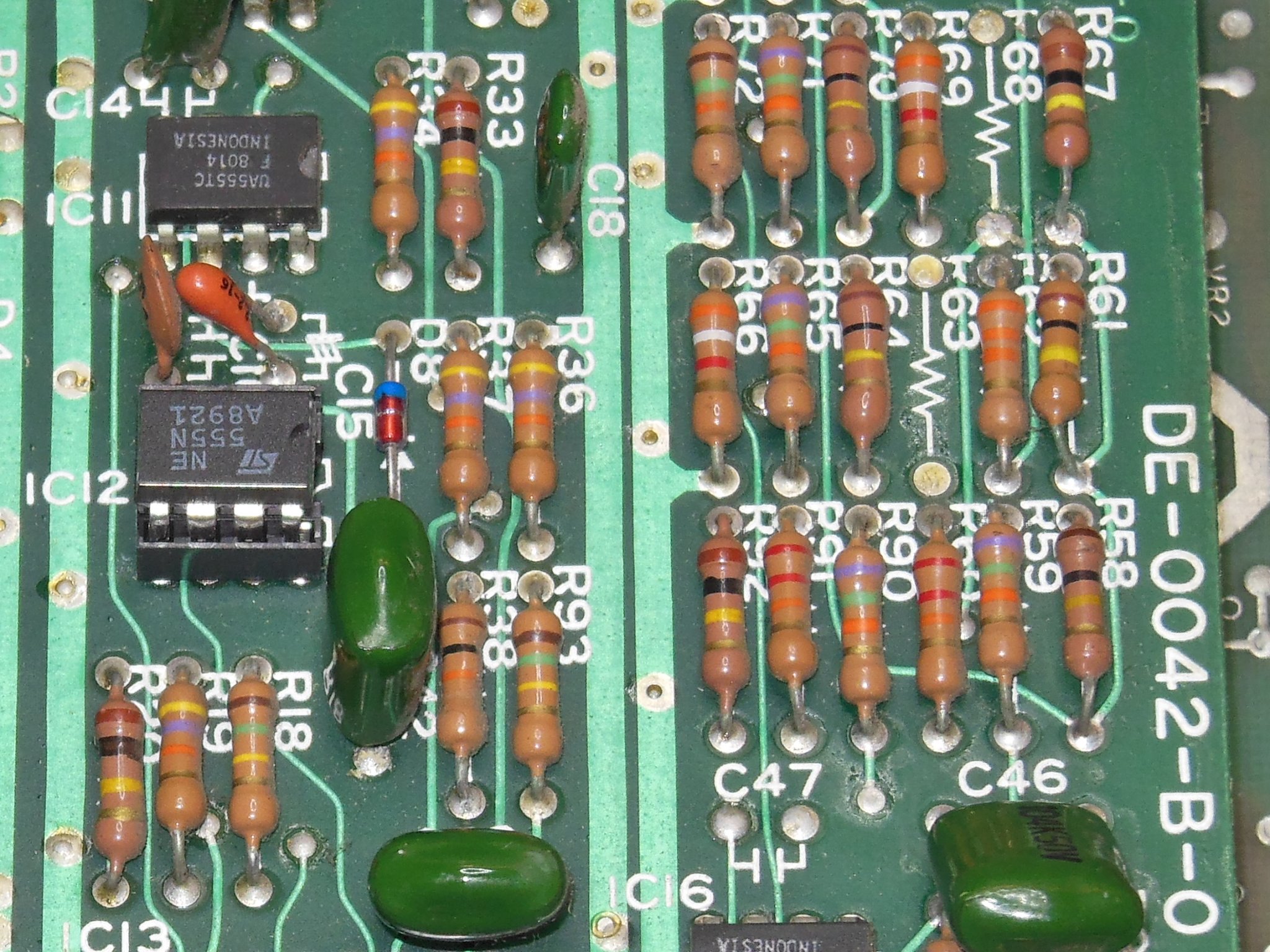
After a few hours of run time I noticed that there was a continuous background tone that seemed to be the tail end of the ship missile fire sound. Checking IC10 (MC3340) pin 2 found no transition on ship fire. The sound control signal transitioned OK at D5 and C19. The base of TR5 had no transition but the base of similar control transistor TR4 transitioned 0V to 1V OK. The resistor R31 correctly measured 215K Ohm so I suspected TR5 (2SC945) was bad. I didn't have any spare 2SC945 but noticed that the Astro Fighter sound PCB was covered in 2SC1815 and no 2SC945 so I wondered if the two were approximately equivalent. Checking the data sheets confirmed the same pinout and similar characteristics, with 2SC945 a 50V 100mA NEC part and 2SC1815 a 50V 150mA Toshiba part. Replacing TR5 with a 2SC1815 (recycled from Astro Fighter) fixed the ship fire sound.
Since I'd added support to the Arduino ICT for checking each individual sound I went through them all to confirm they were all working properly. The sound on data bit 0x10 (labeled "UFO" in the schematics) was missing. Poking around with a scope confirmed the sound was present at the unpopulated R68 resistor pads with nothing at the mix resistor R67. I added a strap across the missing R68 that confirmed the UFO sound was present and working on the PCB when connected. This was a bit of a mystery - the sound generator was populated and working but there weren't any signs that R68 was ever present on the PCB from the factory. Further, the Electro-Sport schematics for the audio board do not show a value for R68 whereas all the other resistors show a value. Without a second PCB set to compare against I wasn't able to confirm a factory error or intentional omission and thus left the UFO sound disabled.
|
Whilst testing the sound on the bench I noticed something strange with the writes to the protection register using the Arduino ICT. The write & read of the protection register at 0x8007 with data 00 & FF was correct but the write triggered sounds. Checking with the scope confirmed that a write to the protection address triggered a pulse on both the protection latch and the sound latch (at address 0x8006). I suspected that the address decoder IC 3A (7442) was bad. I setup the HP comparator that flagged the outputs mismatched for the protection write confirming IC 3A was bad. I also checked the other 7442 decoders in this circuit, IC 6F & 2A, that additionally flagged IC 2A as mismatched. Replacing IC 2A & 3A (noting the patch wire location) fixed the write/read of the protection register and the game ran OK for several more hours.
|
A few more hours of burn-in testing didn't encounter any further issues.