
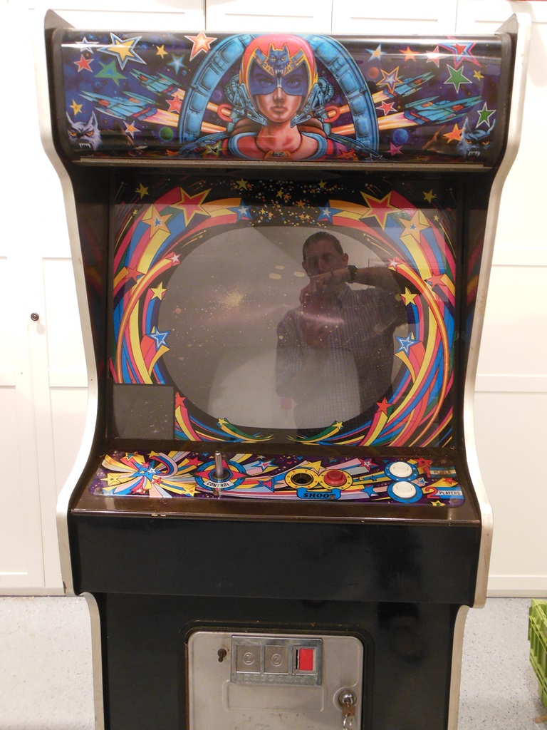
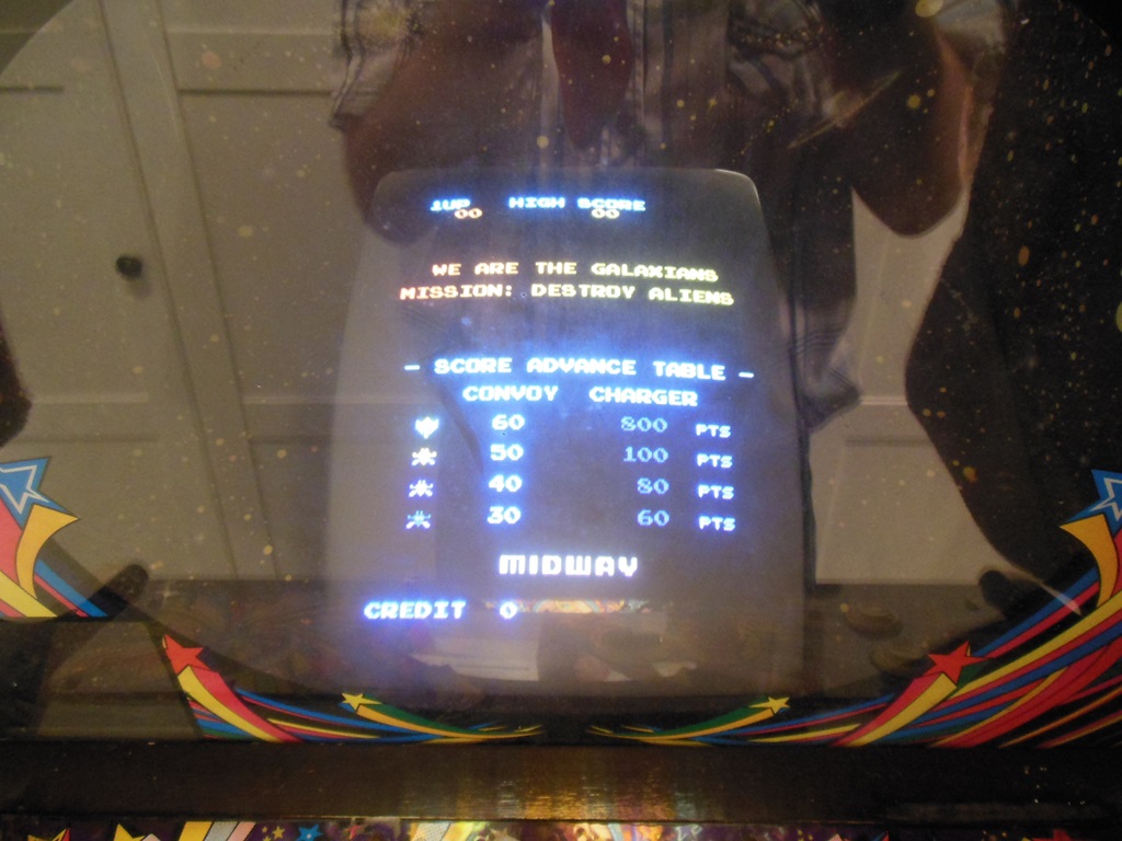
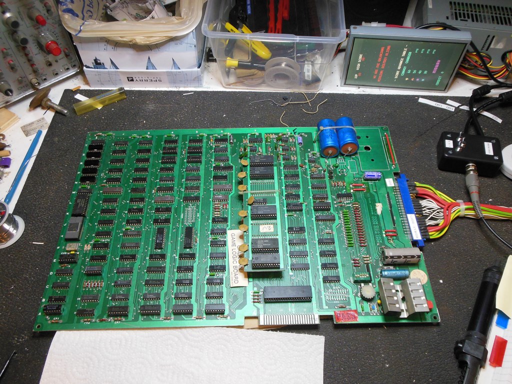
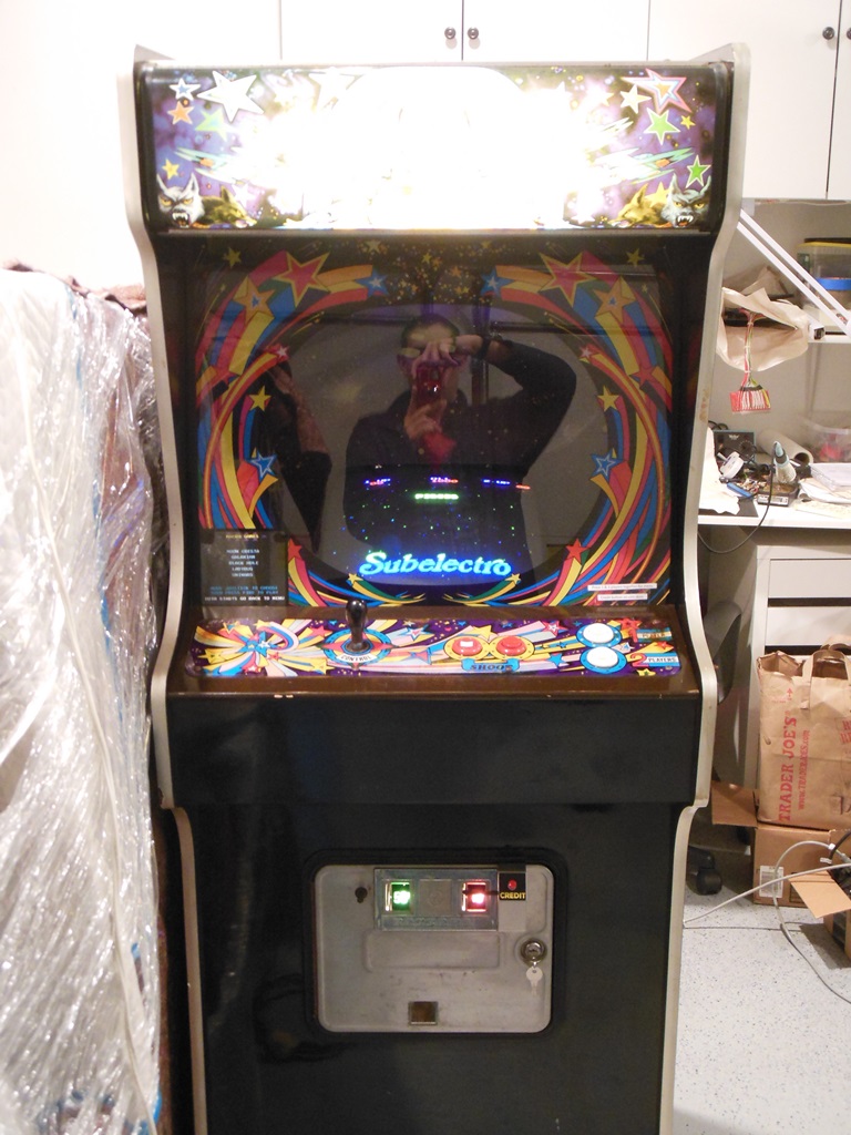
This was the first Zaccaria game I ever bought in the UK and the one that started the Zaccaria collection. It came from Suffolk either from the same guy I bought my first game from (a Tehkan Phoenix) or through the local small ads. Originally the cabinet contained (and was wired for) Pengo but clearly this wasn't it's original game. It also looked like the control panel wasn't original, being mismatched in colour. When I first got the game I repaired the wiring and converted it to Galaxian using a Midway boardset. Since it's been in the US, the Universal joystick and single button control panel overlay that used to be on this cabinet was moved over to the AL Mr. Do! cabinet since they were the right parts for that.
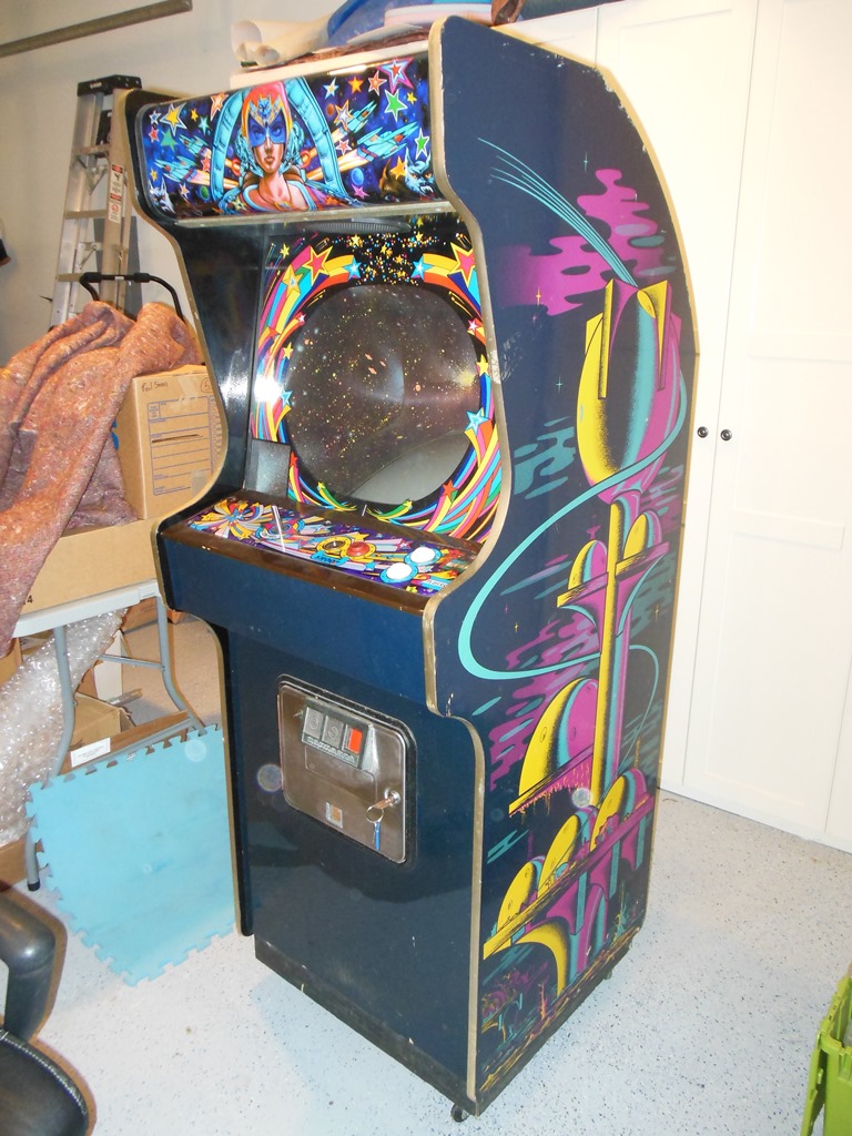
The cab is still a mystery after all these years. The marque is very similar to the
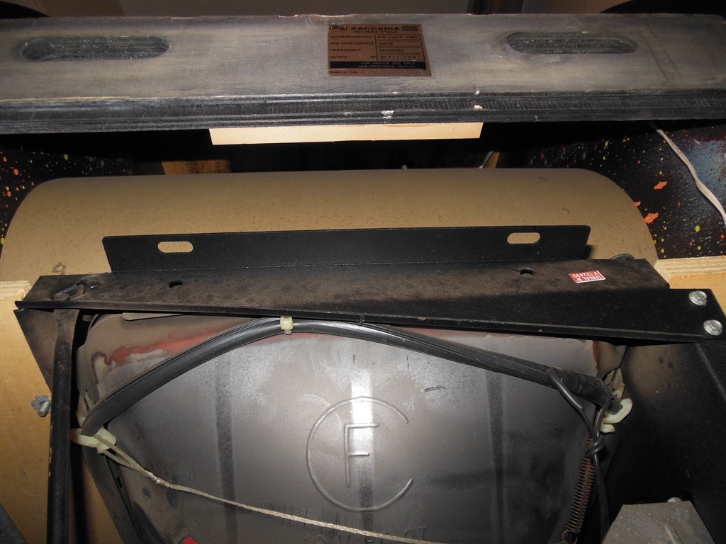
Midway Solar Fox marque but no game name is present. Date wise, the horizontal mounting
power brick and "space city" style side art suggests circa 1981. There is no game name
label on the power brick. Since working on it a little bit there are a couple of other
interesting clues:
|
|
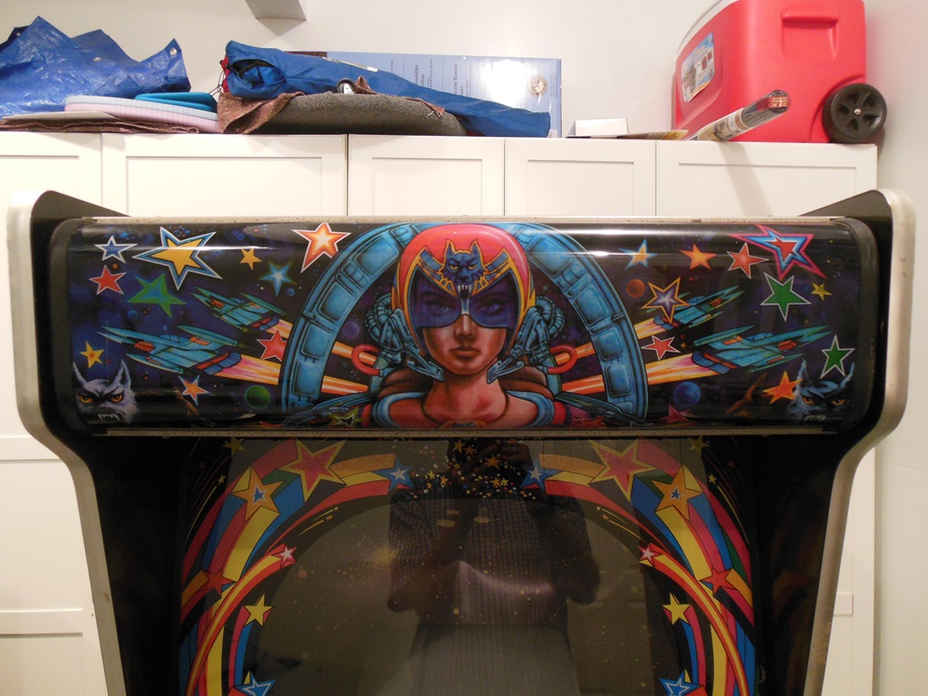
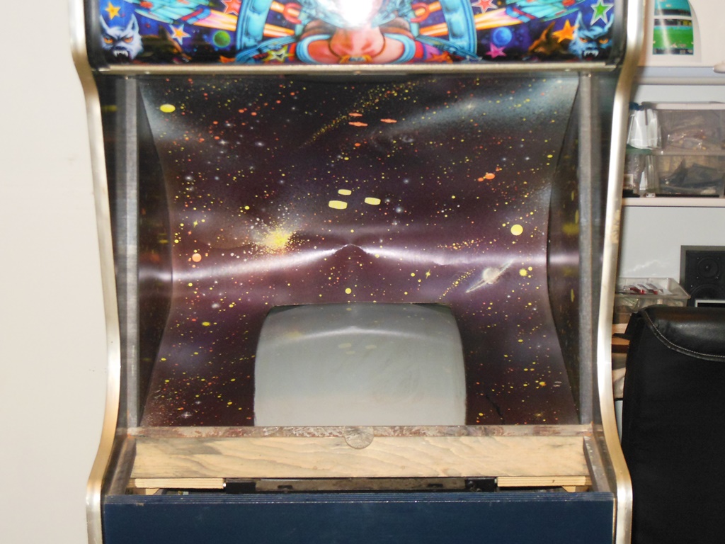
The cabinet is is in pretty good condition.

|
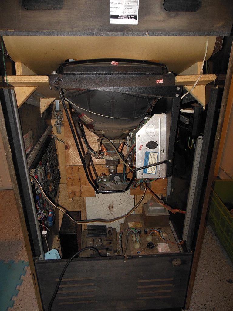
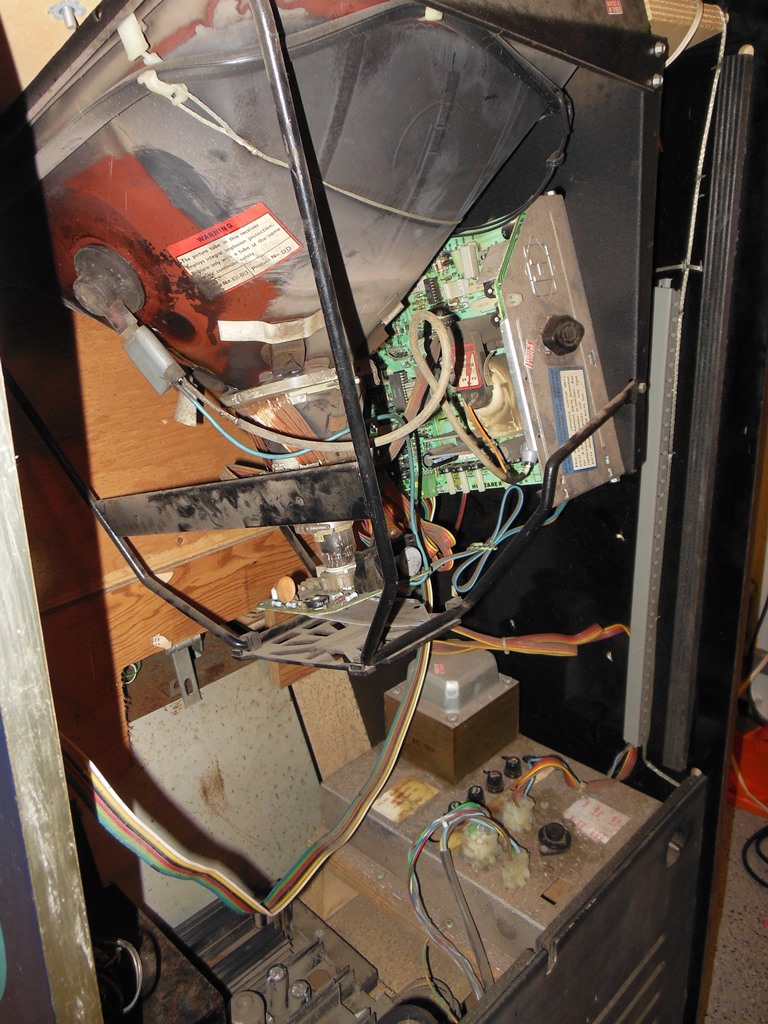
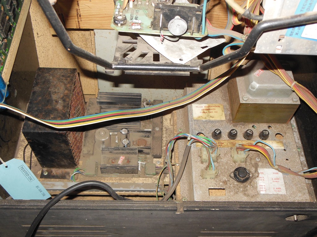
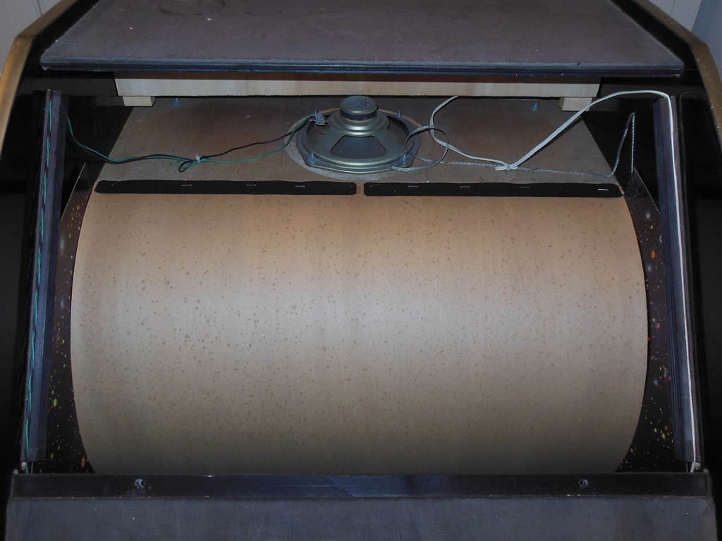
The inside is mostly original. There are staples and paper fragments likely from the dipswitch sheet for the original game.

|
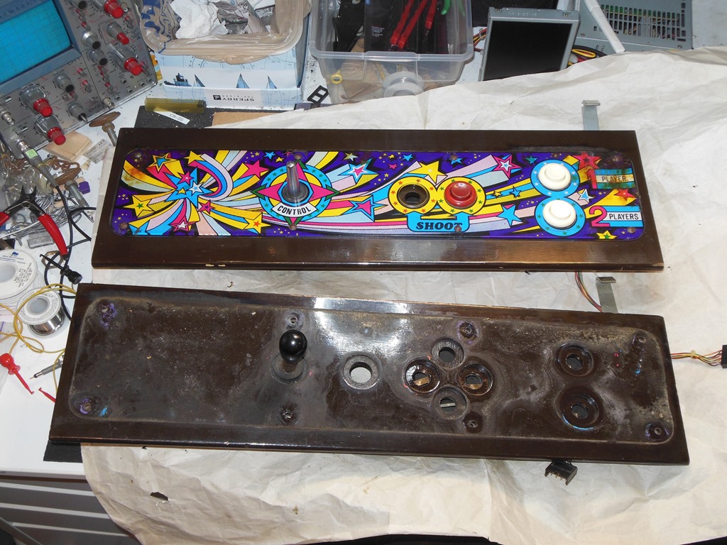
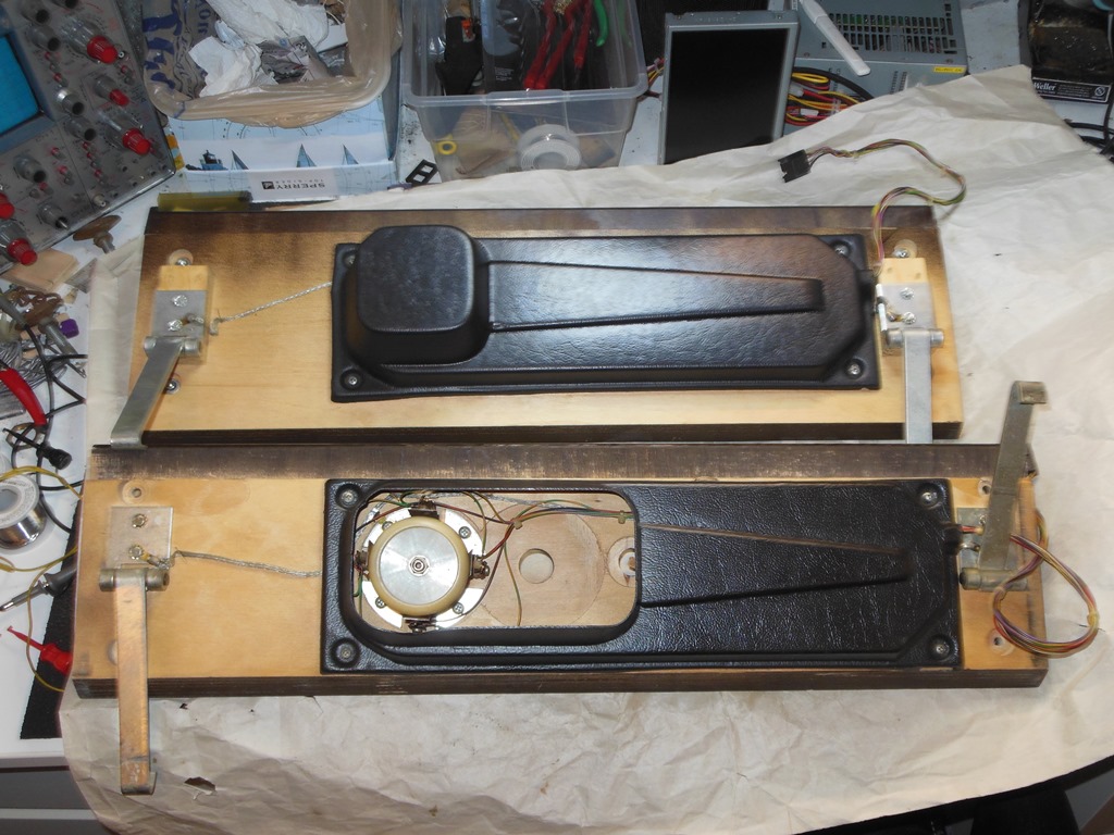
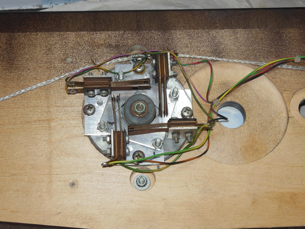
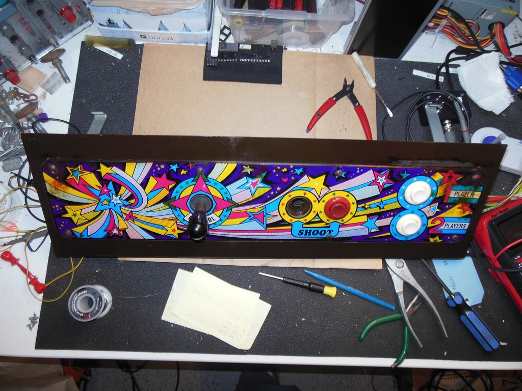
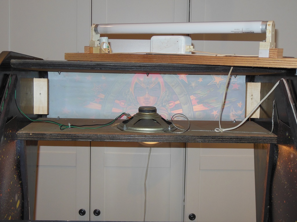
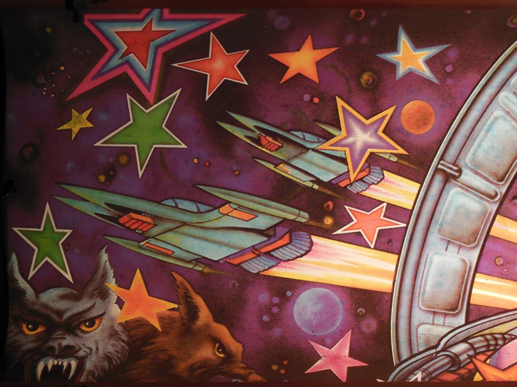
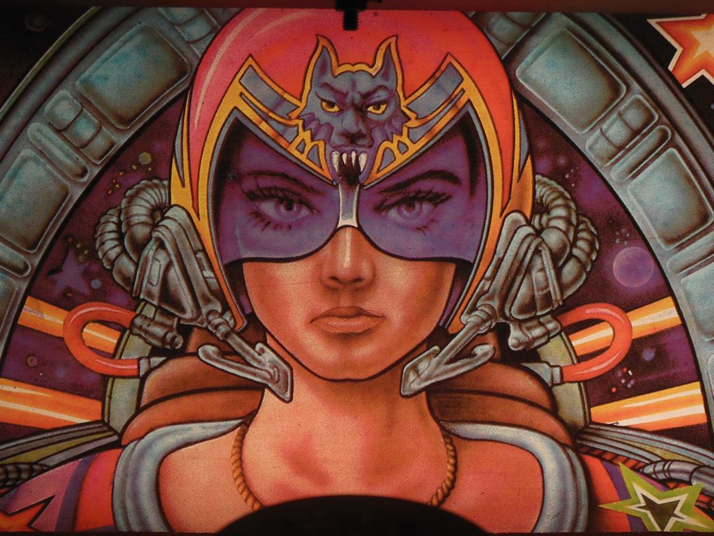
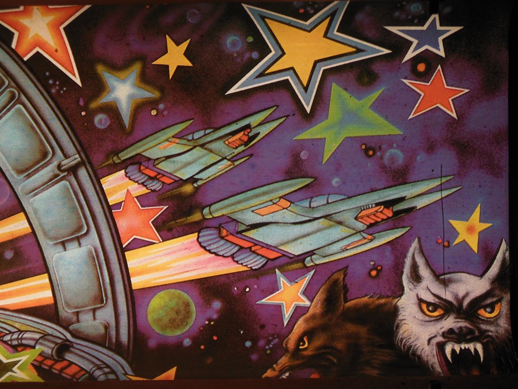
The marque is in excellent condition and the star of this cabinet. The control panel as was on this cab was in excellent condition, though now it had a poorer condition two button overlay and a temporary chrome stick. The power assembly was very dirty but complete. The fan was completely shot (I'd already unplugged it when I first got it years ago).
|
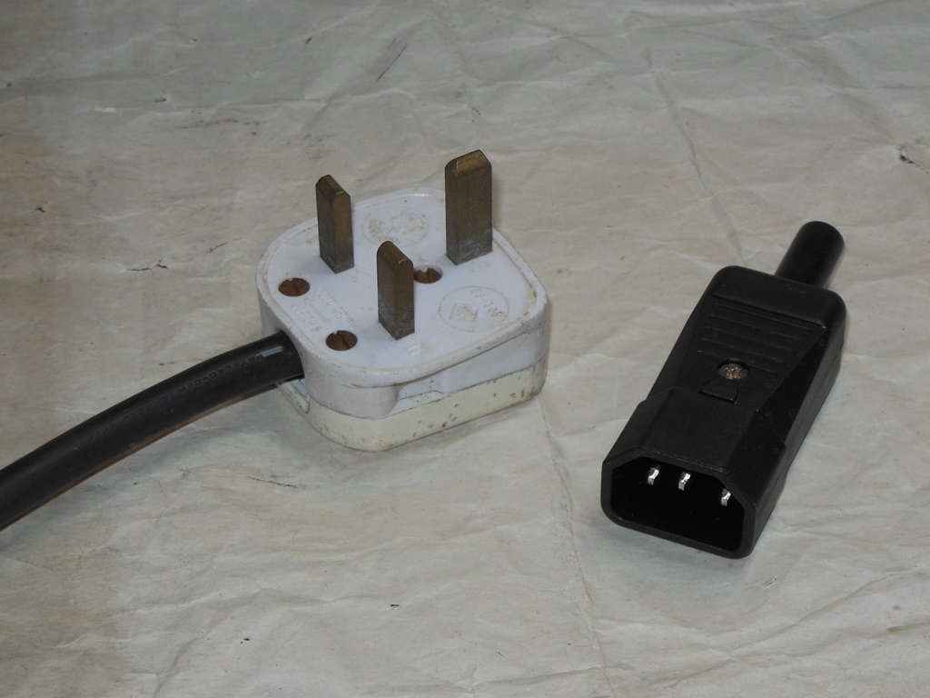
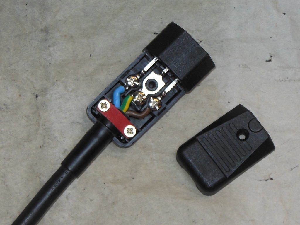
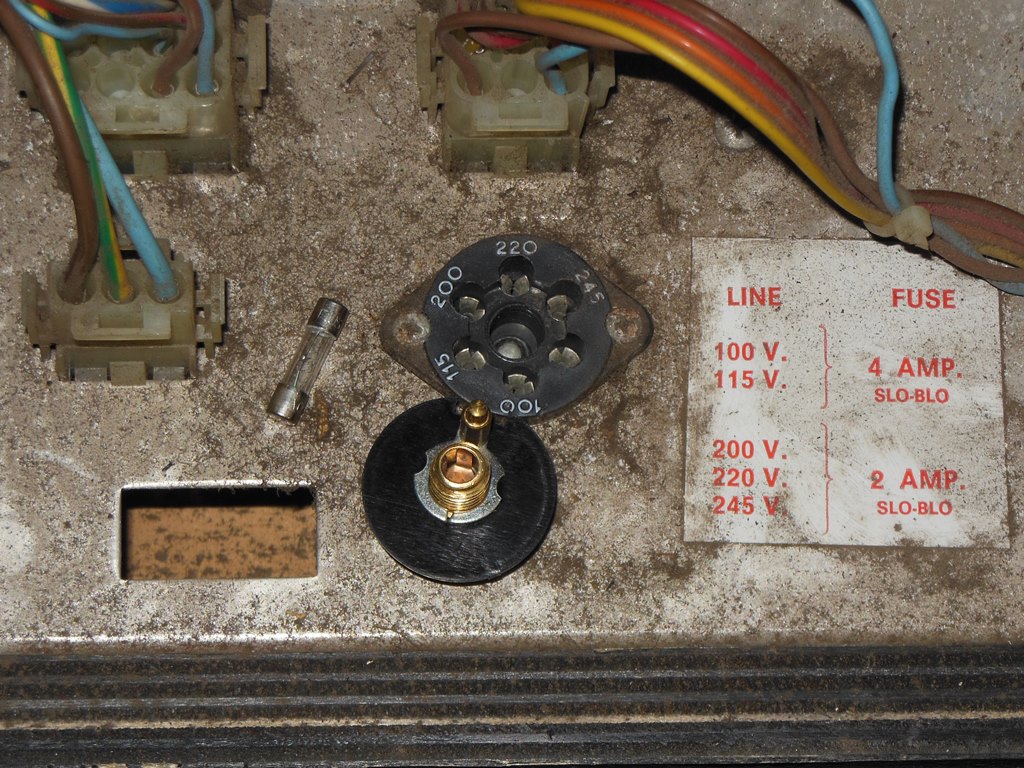
Replaced the UK style plug with the IEC C14 style plug I've been using in the US for 240V games.
|
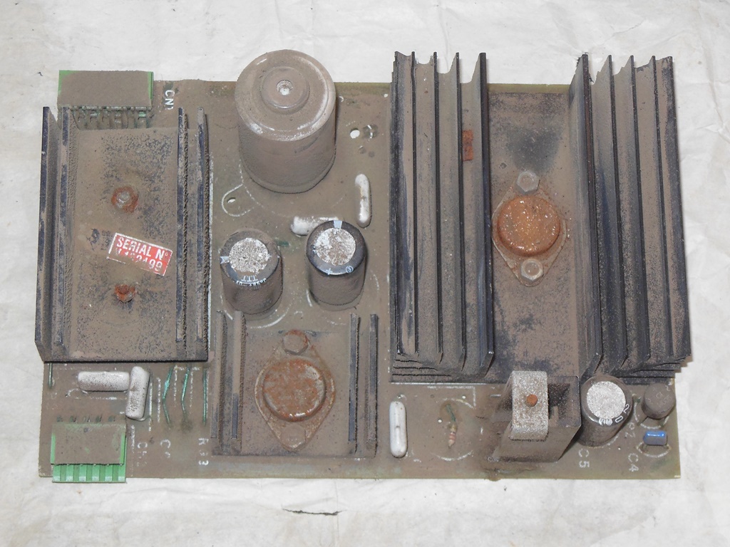
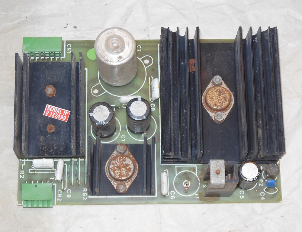
I decided to clean up the 1B1126 regulator board first since it was especially dirty using a Dust Buster aerosol.
|
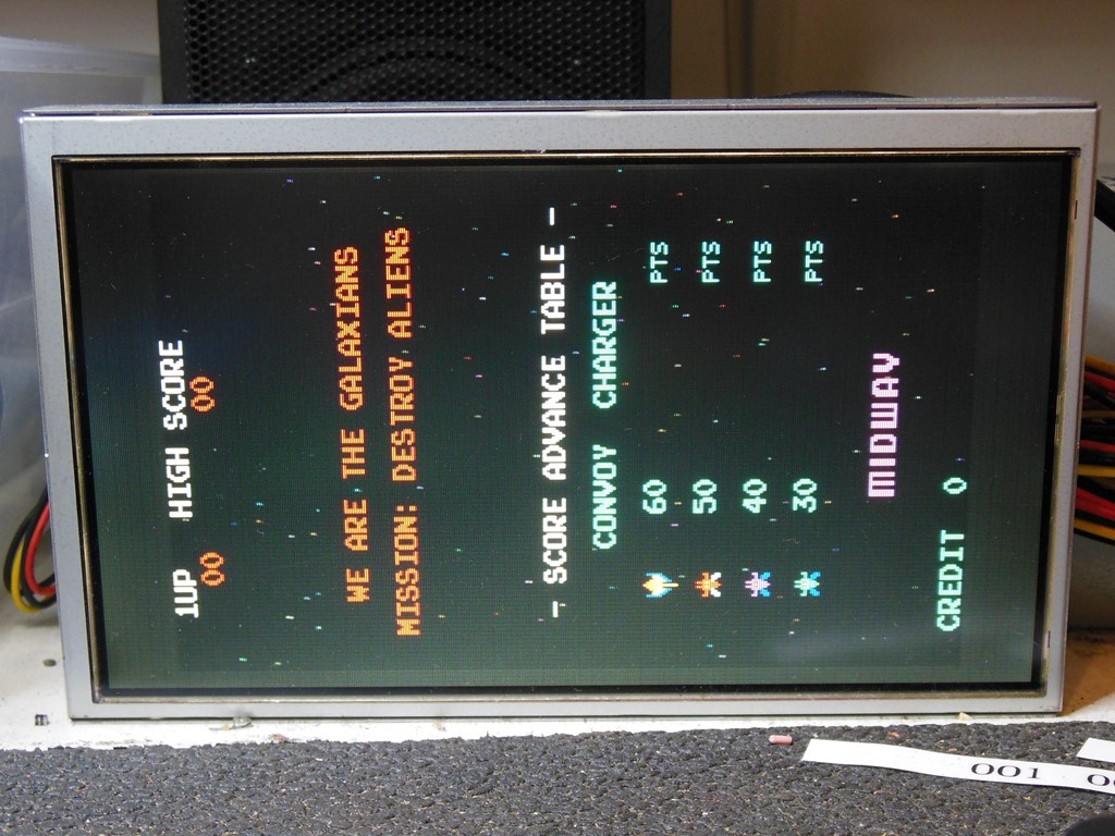
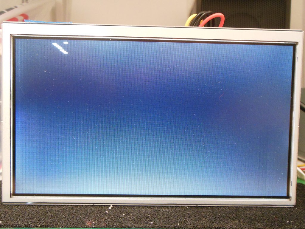
First power on yielded nothing at all. Tracing with a multimeter showed no AC at all out of the power brick. The line input fuse was open (not blown, just corroded open). Replacing the fuse brought more life - the game ran with a good picture and mostly working game board. The only problem was a lack of stars, missing ship explosion and bad ship fire sounds.
|
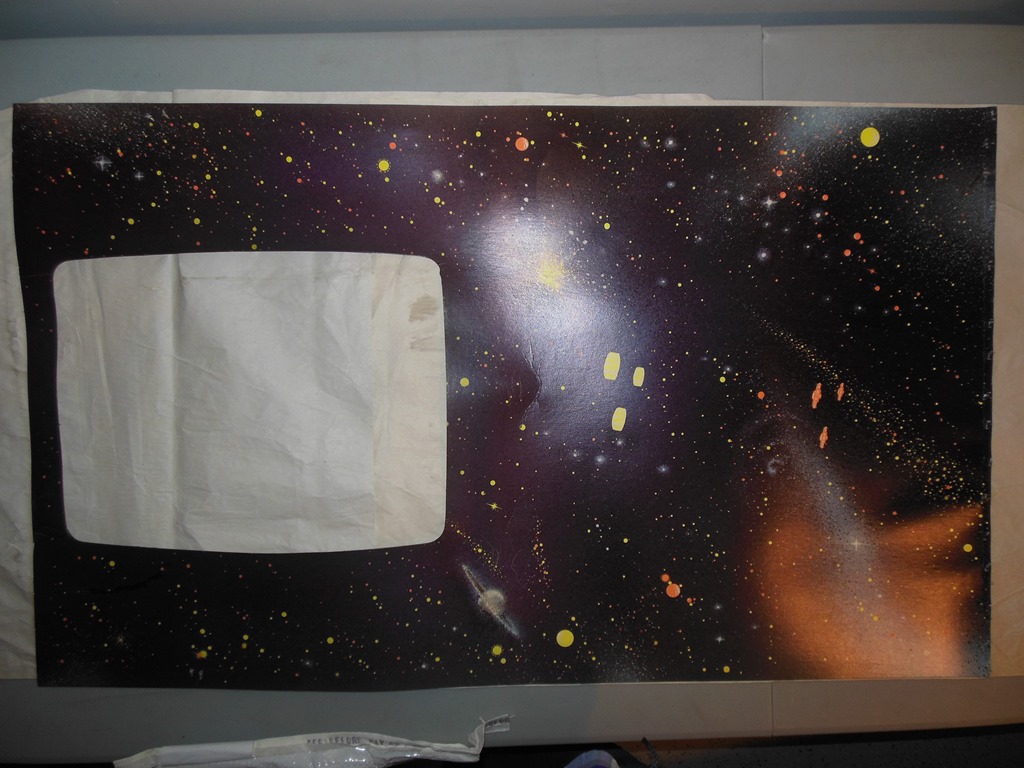
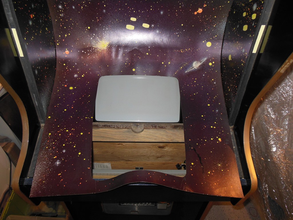
The monitor surround is in good condition - there was a crease in the back curve that I decided to leave as is for now and a small tear in the corner of the monitor cut out that I decided to tack back together.


|
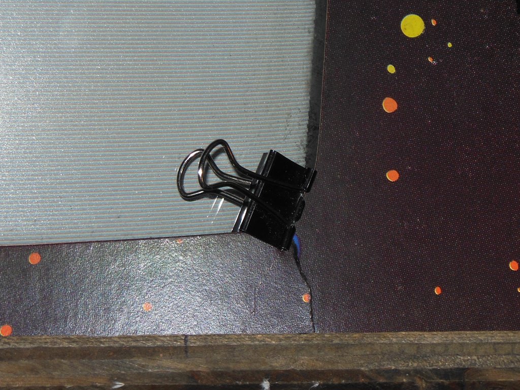
The foam spacer between the monitor glass and the wood frame was long since rotted away so I replaced it with a double sided foam tape strip (leaving the paper on the glass side). The glass itself needed only cleaning and was otherwise in good condition.
|
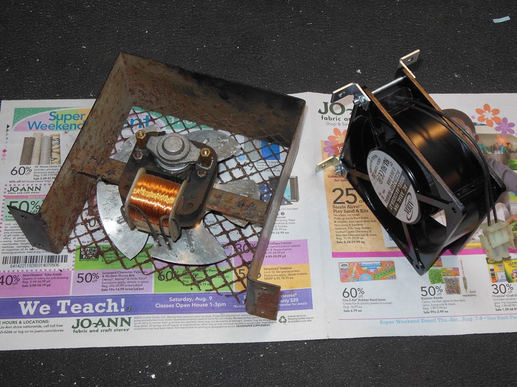
I replaced the original fan with type I've been using for a few cabs now that have been through several days of runtime without issues, an ADDA AA1282DB-AT (220-240V 50/60Hz) mounted onto simple 3/4" corner brackets.

|
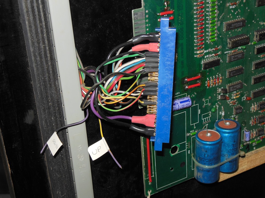
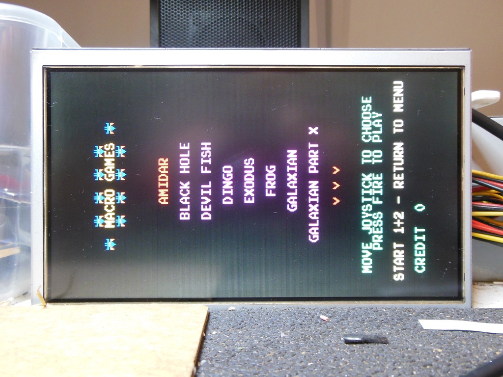
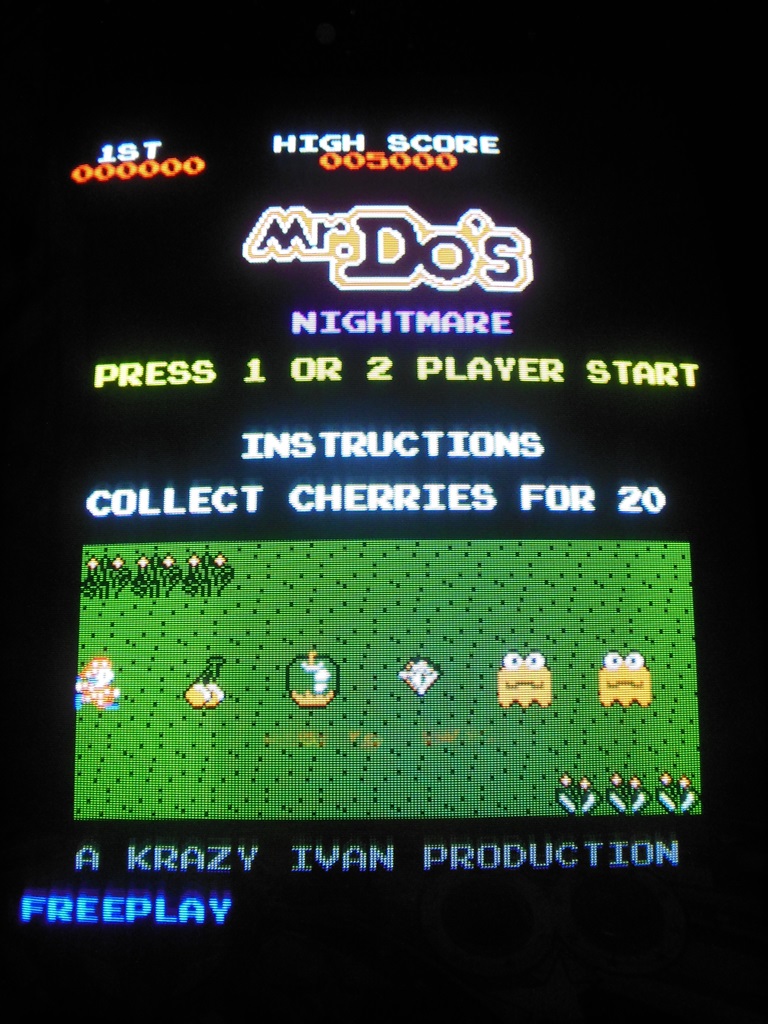
Since Galaxian doesn't use up and down, I'd left those connections off but labeled for future use. Macro's Galaxian multigame does use up and down for some games it supports, such as Ladybug and Mr. Do's! Nightmare, so I connected up and down based on that wiring ready for when the multi-game kit arrives.

|
The missing stars, ship explosion sound and bad ship fire sound were all indicative of a problem with the feedback shft register circuit used as a random signal generator. Since it's a feedback based circuit it can be quite hard to determine where a fault with it may be. This time was no exception - the circuit was running and there was a noise signal but it looked like it was much higher frequency than it should have been. The whole circuit looked like it was not far off being a clock of the MHz order. The first step was to take a shot in the dark and replace the first shift register in the chain, a 74LS164 @ A1. This didn't change anything when replaced but removing it allowed the feedback path into the start of the circuit to be opened. Using a hi/lo pullup switch onto the feedback input of the 2nd divider in the chain, another 74LS164 @ B1, allowed the circuit to be run in a more controlled way. Tracing through with a scope revealed that the 74LS74 @ D2 was bad (oddly giving a clock output on Q when the D input was high). Replacing the 74LS74 brought the stars back and fixed the sounds.
|
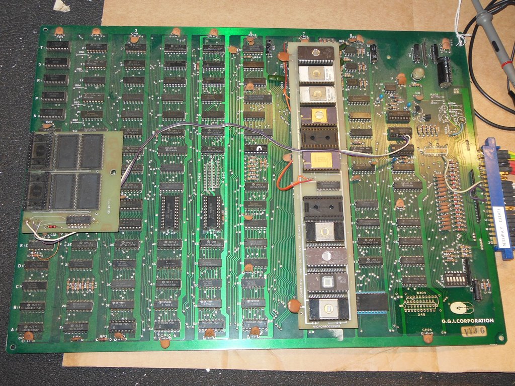
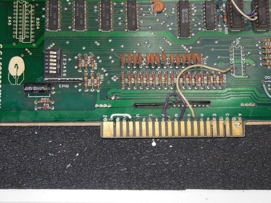
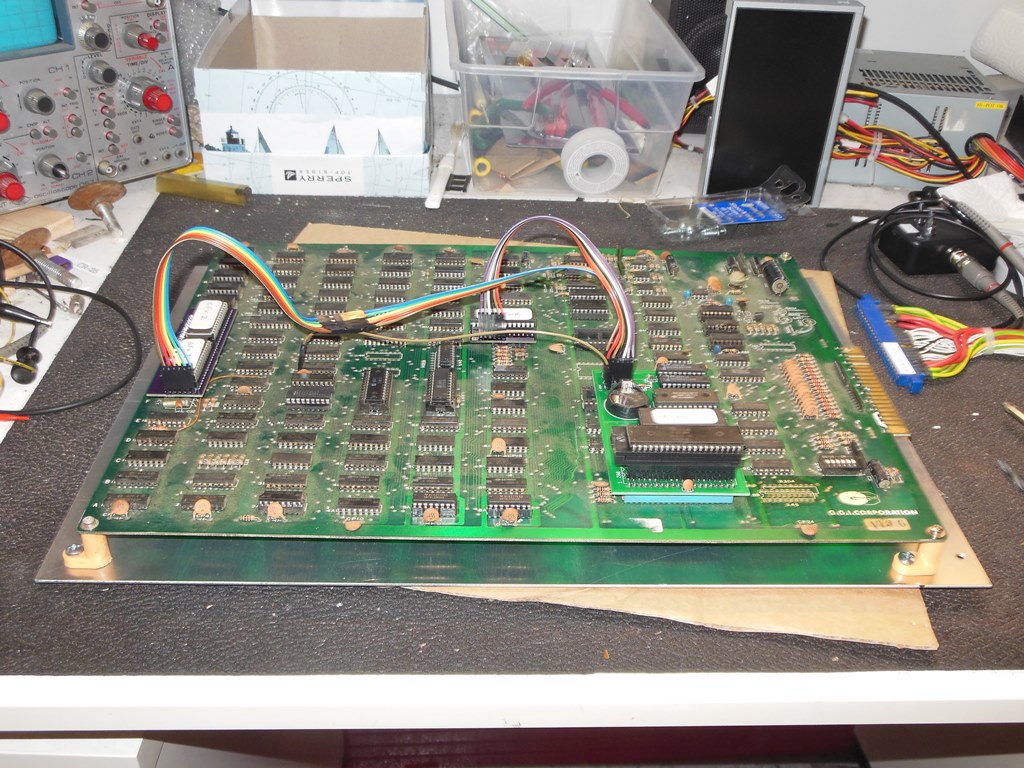
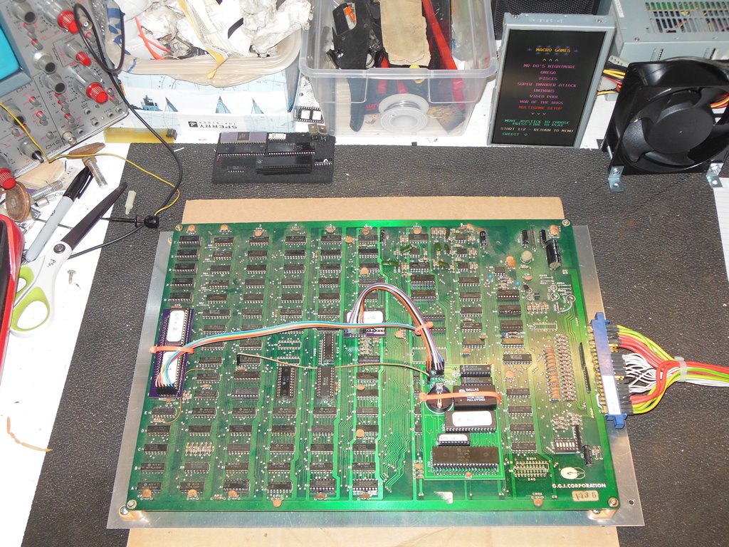
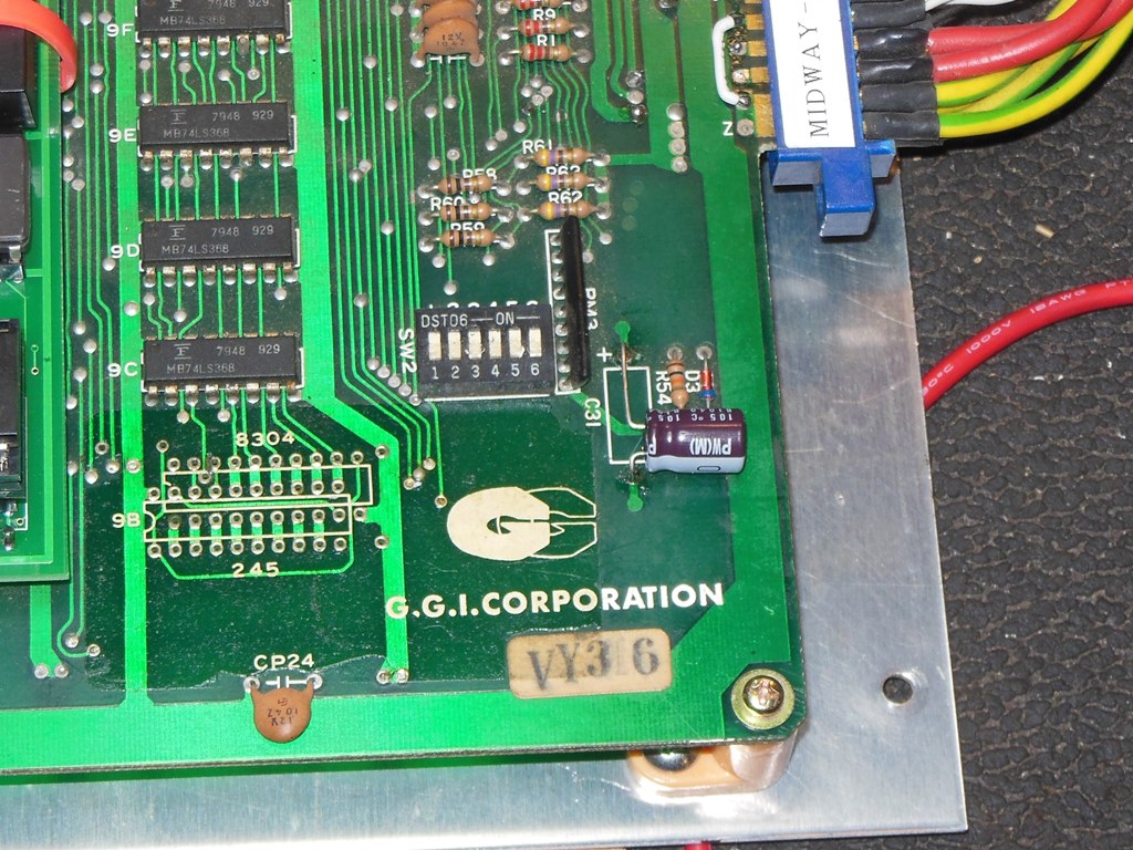
Well, I was having an ethical dilemma about converting the otherwise original Midway board, with original mask ROMS and soldered original colour PROM, into a multi-game. I decided to dig out a couple of boxes of bootleg Galaxian boards to look for a decent one of those to use for the multi-game. Most of them were pretty severly hacked up and really poor quality. However, one was quite a nice G.G.I. Corporation bootleg with a number of attributes that made it worthwhile to get going:
|
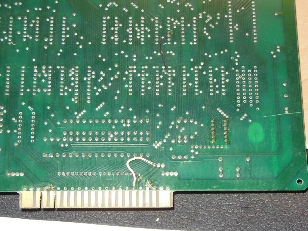
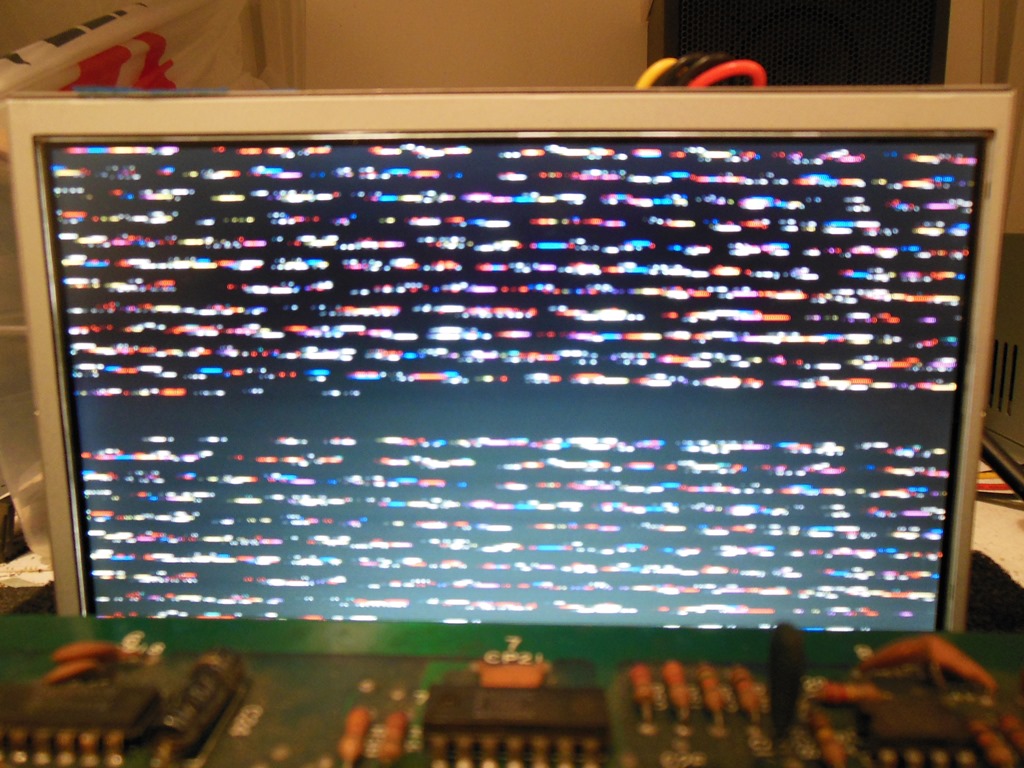
On first power on there was a rolling screen and the scope showed no sync output from the board. However, the sync at R64 looked good. Looking at the hacks on the board it became clear that the video outputs had been hacked to a different pinout. After undoing those hacks the video output looked more reasonable with sync locked. There was also no audio output that was fixed by adding a strap from the second speaker pin to ground.


|
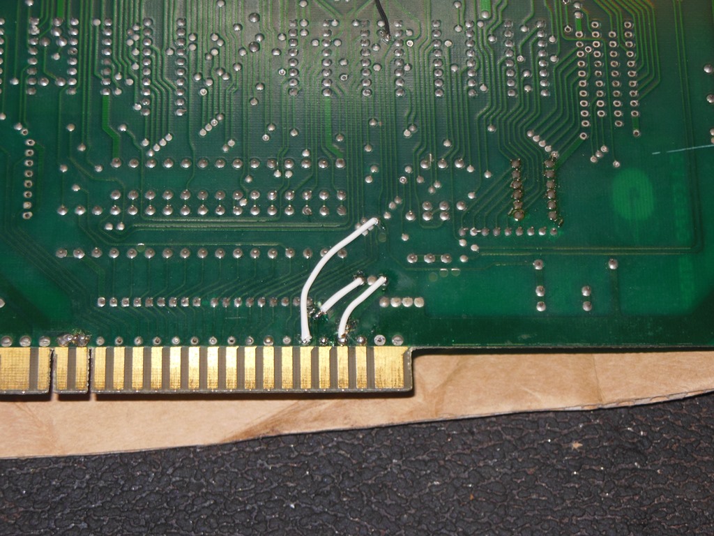
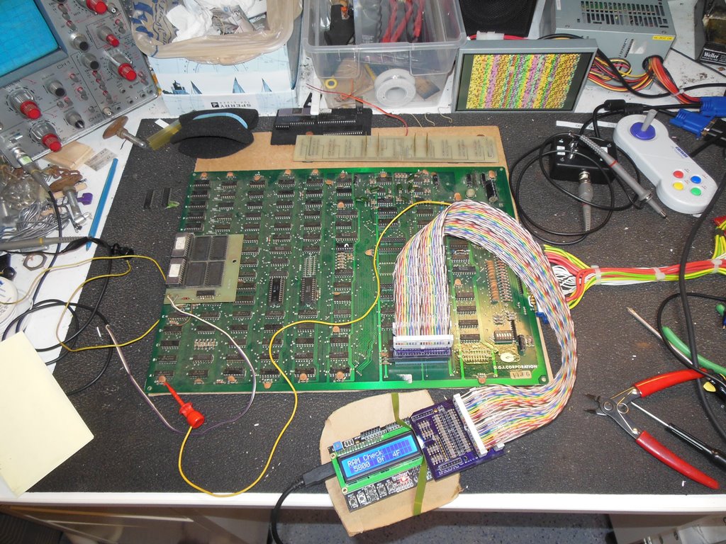
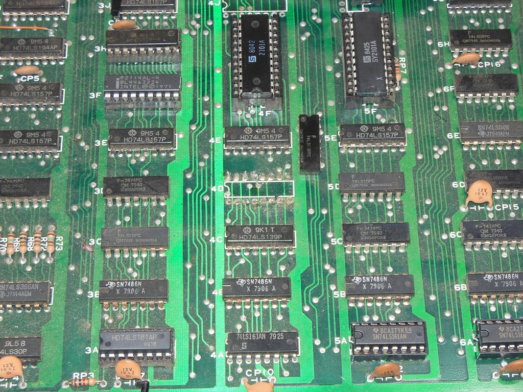
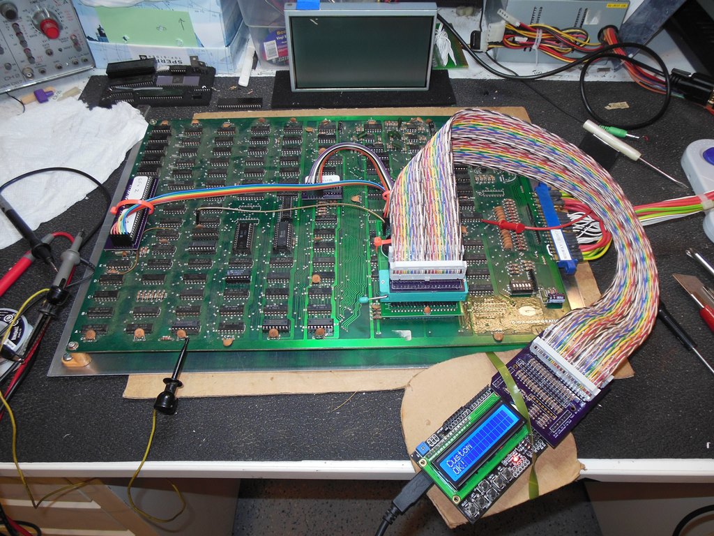
Initially there was no sign of graphics and the more astute reader may have noticed that the boards graphics ROMS were missing. Borrowing a pair of graphics ROMS from an unknown game showed the game was continually restarting with a bad ROM/RAM message. The "Scrumble" ROM board included a larger RAM that replaced the pair of 2114 program RAM with more memory. On a hunch, I assumed that all the similar remaining hacks needed to be undone and put back to as manufactured EXCEPT for the one identified by the photo above in the graphics section that I verified with the schematics as a repair for an apparent manufacturing defect in the board tracking and thus left as is. With all that repaired I discarded the "Scrumble" ROM board that would no longer be useful and moved on to debug using the Arduino In Circuit Tester.
I'd already brought up the ICT on the Galaxian platform using the fully working Midway board. On this board both 4F & 5F (2101) RAM tested bad. Replacing both of them fixed that RAM test. Next the tester reported bad RAM 3F (2114). On replacement of the RAM the test still failed. Using the tester to perform read/writes and poking around with a scope showed that 3F pin 12 was bad (pulled high). By changing the RAM I'd already confirmed it wasn't the RAM so I suspected a bad driver on the line (either 3K or 4K pulling high). After cutting the pin at the 8216 the line looked good suggesting that the 8216 at 4K was bad. I didn't have any spare 8216 and an Ebay search showed they were relatively overpriced so I decided to take the alternative stuffing option of a single 74LS245 to replace both the 8216. With that fixed the RAM test passed (the original 2114 was also bad).
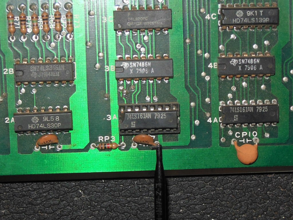
The next problem was that the characters were repeated and scrolling across the screen. Further, the video blanking interrupt wasn't firing. Taken together that hinted at a problem with the video counters. The LS10 @ 5D pins 3,4,5 were idle. Looking at the LS161 @ 6A, it had good clock on pin 2. 5A inputs looked OK and the output pins read 10 (OK), 11 (Lo), 12 (OK), 13 (OK), 14 (OK), 15 (Lo) and LD (load) on pin 9 (Hi). Pin 11 that was stuck low was the 16V count output that should have been running. There was also no activity on the carry output. Replacing 5A brought 16V back along with more graphics but the screen characters still scrolled and there was still no VBLANK interrupt :( Moving on to 6A showed pins 10 (OK), 11 (Hi), 12 (OK), 13 (OK), 14 (OK), 15 (Lo). Again it was pin 11 that was stuck (high this time), the VSYNC output. Replacing the LS161 @ 6A stopped the graphics from scrolling and fixed the VBLANK interrupt. With all ICT tests passing the next step was to try the multi-game.
|
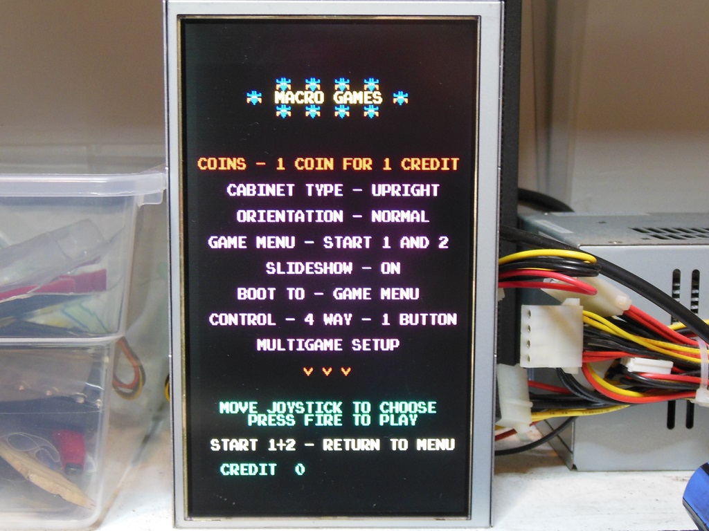
After building and fitting the kit the game booted into the menu on first power on :). However, I wasn't able to select a game. Troubleshooting with a meter revealed that I missed a small cut that had been made on the edge connector pin for player one fire that had disconnected it. Putting back the connection fixed the input and I was able to select and play Galaxian to verify the sound circuits. Something was off with the rack but I couldn't easily tell what exactly was wrong with it. Going back to the ICT I programmed the rack enable bits FS1, FS2 & FS3 that indicated FS2 & FS3 had no output when enabled. However, all three showed output at their respective 555's. It appeared that the sound output was being dropped over R24. Measuring the resistor showed that it was correct @ 10K ohm. Measuring all three of the mixing resistors showed that FS1's R30 was 1K (as in 1K was fitted) and FS2 & FS3 had 10K mixing resistors. The schematic showed R30 as 10K and a cross check with the Midway board showed 10K was fitted on that. Therefore, as far as I could tell the 1K was a manufacturing error. This was having the effect of pulling down the two other channels in the mix such that the rack didn't sound right. I had a look around the board measuring resistors and comparing them with the schematic. Low and behold, in the colour output resistors I found R78 that on the schematics was shown as 1K but on the GGI was 10K. Therefore, I simply swapped the two resistors to correct both manufacturing anomalies. Finally everything was working perfectly.

|
|
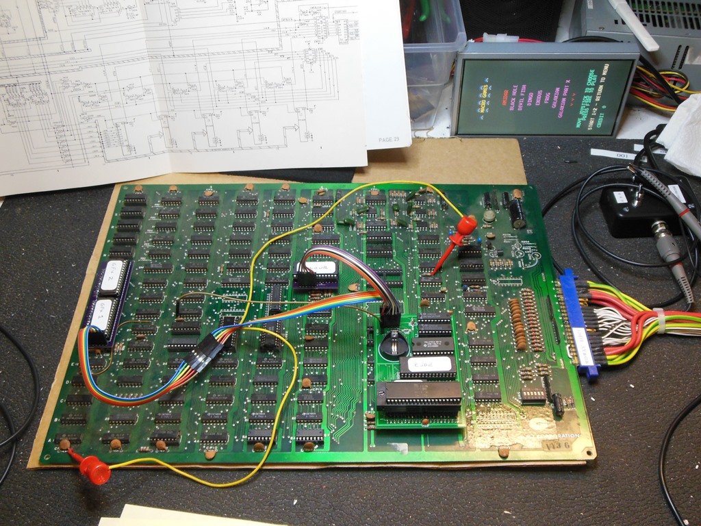
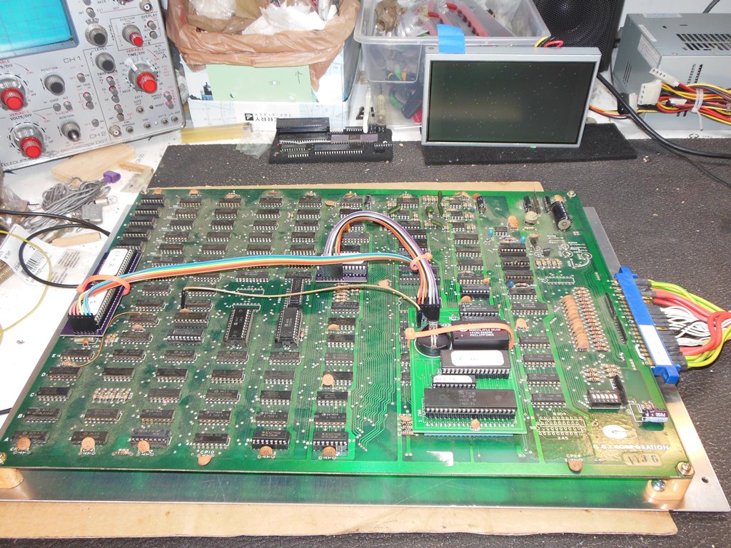
Gasping for a game of Moon Cresta I fitted the board loosely into the cab and played some games. The monitor picture looked pretty good even though the chassis was still on its original caps. Just a little bit of uneven green on Nightmare not significant enough to bother with.
|
The joystick on this cab was a chrome stick borrowed from a spare control panel that had a snapped spring so it was pretty poor to use. Another spare control panel had a more traditional topped joystick that I decided would go well in this cab and was worth the effort to swap over.
|
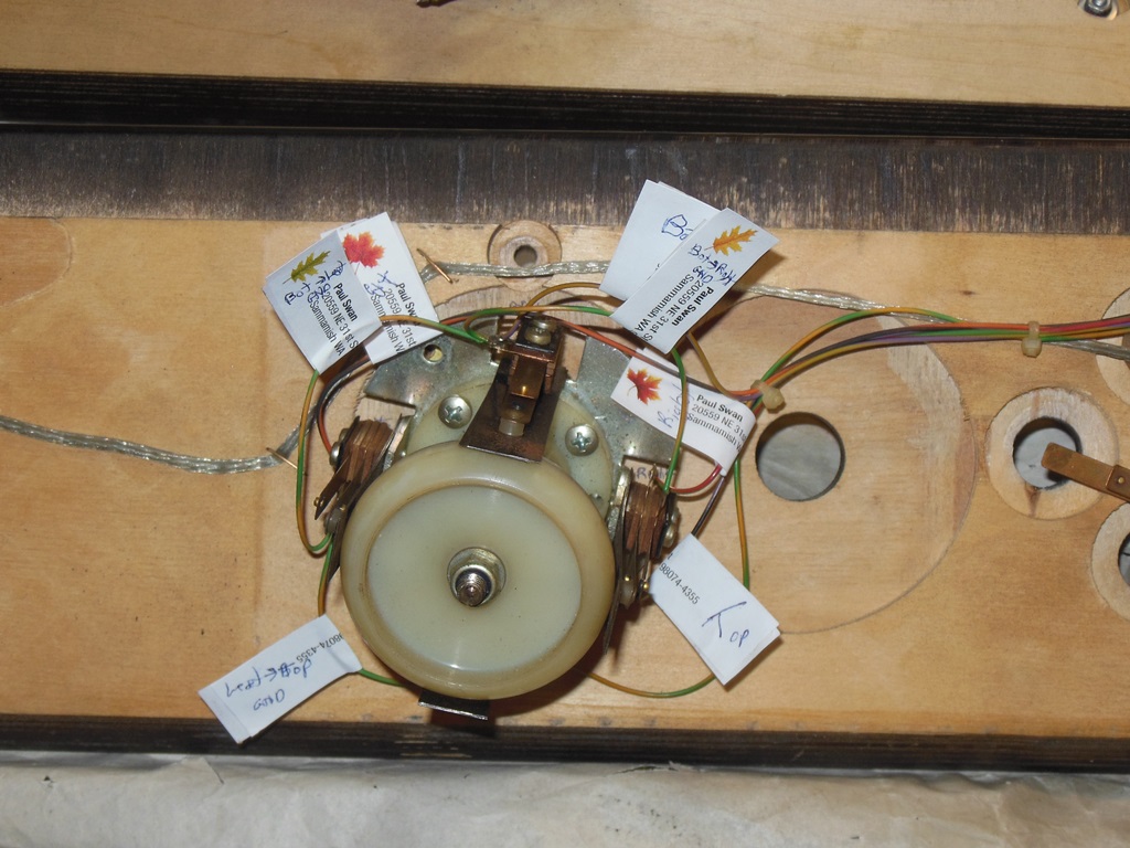
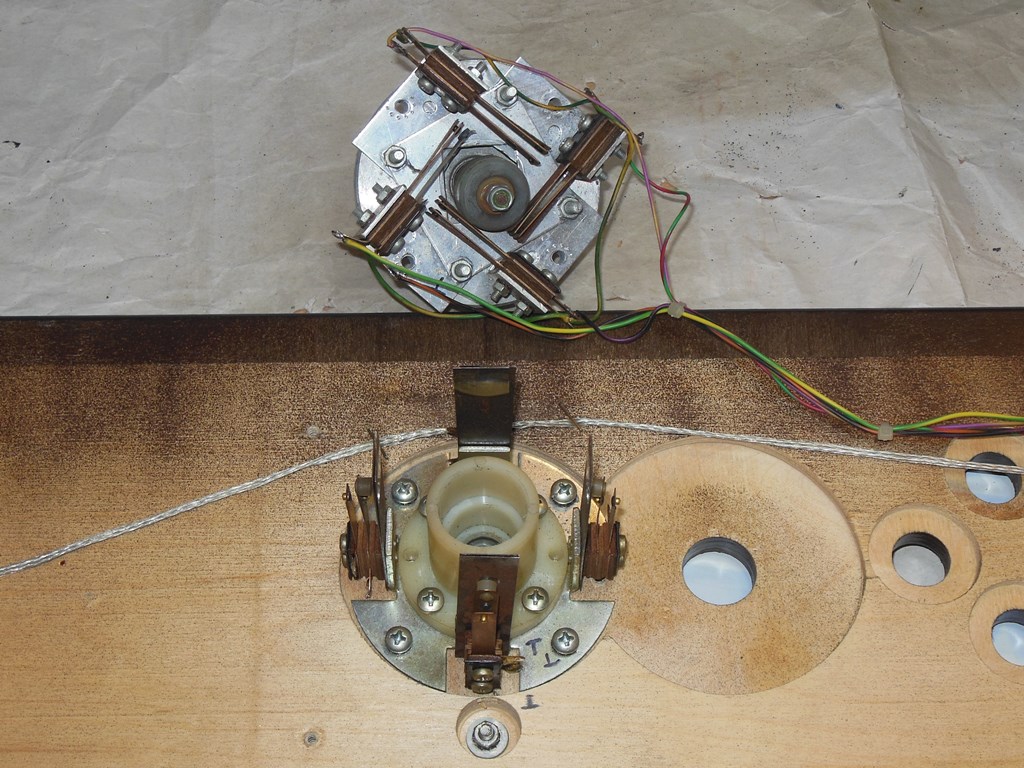
The physical mounts of each were compatible so there were no wood work changes needed other than slightly different mounting screw holes. The donor control panel I may use at some point in the future so I labeled all the wires before de-soldering them and removing the stick. The destination panel didn't need any labelling as I moved over the wires one-by-one taking care to note the different locations of the tabs due to the different leaf switch positioning.
|
With the new stick fitted game play was much improved :)

|
Using one of the repro plates from a prior Online Metals order (from the second batch that was slightly wider) I marked and drilled the holes for this board and fitted it.
|
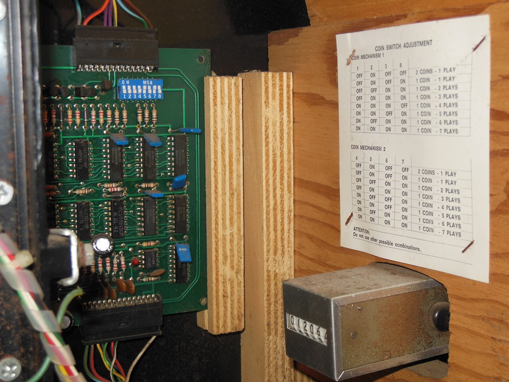
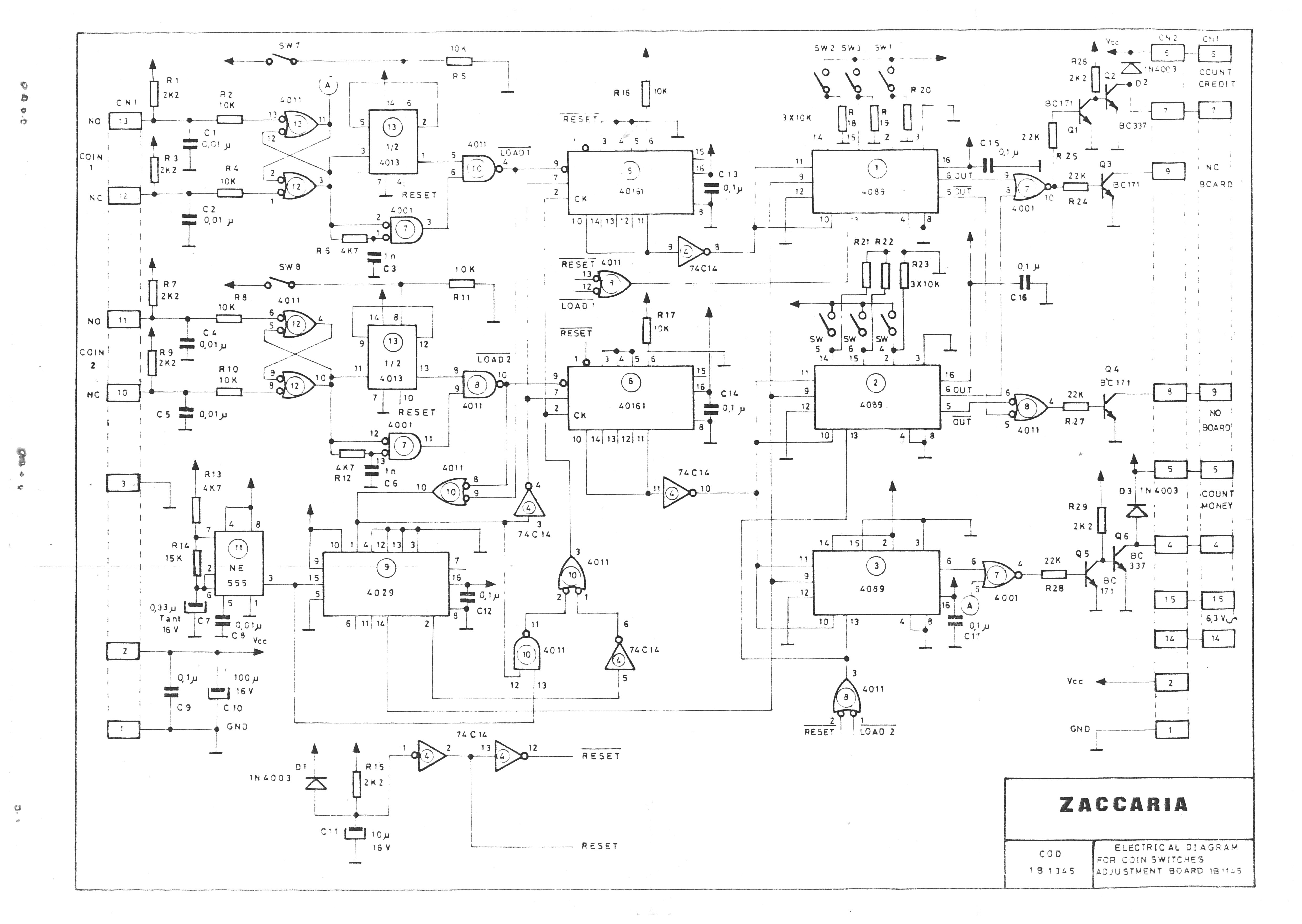
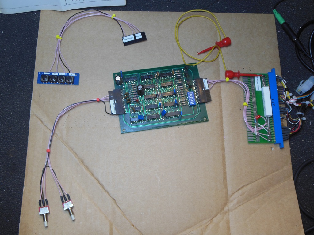
I'd been running the multi-game on free play but noticed that most of the games didn't cycle through attract mode when set for free play and I prefer to see attract mode. Switching the multi-game to 1 coin 1 credit revealed that the credit board in the cabinet wasn't working. I'd already built a test harness for the later 1B1185 series credit board that was partly reusable on this board - I needed to make a new button harness to reflect the 1B1145's dual NC/NO inputs (versus the 1B1185's triple NO inputs).
Neither coin input was working and there was neither credit nor counter outputs from the board. Coin 1 input was OK at IC12 (4011) but there was no output at IC13 (4013). Studying the schematics a little bit suggested that the NE555 output pin 3 was a clock used to drive the circuits on this board. There was no output from the NE555. Replacing the 555 brought back a clock and fixed the credit board.
|
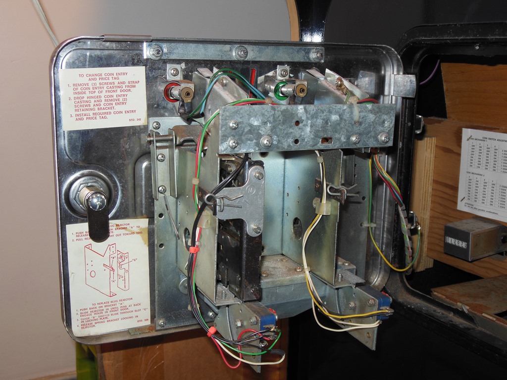
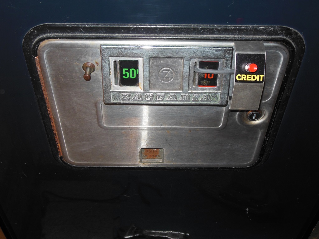
With the multi-game now back on credits I needed to fit a credit button and also at the same time fix the coin entry slots and door lights. This cab had one coin entry covered with a blanking plate and the other had been painted red. I extracted a pair of 10p/50p slots and related hardware from one of the Duke of Lancaster Astro Wars cabs and fitted them on this door. I also made up a 3-way (NC/NO) credit button and fitted that. With the coin door light bulbs replaced there were still no coin door lights. Working back with a multi-meter showed no 6.3VAC at the credit board and in fact no 6.3VAC out of the power brick. Checking the fuse revealed that the fuse was oxidized and after cleaning the contacts with some fine sandpaper the door lights were working :)
|
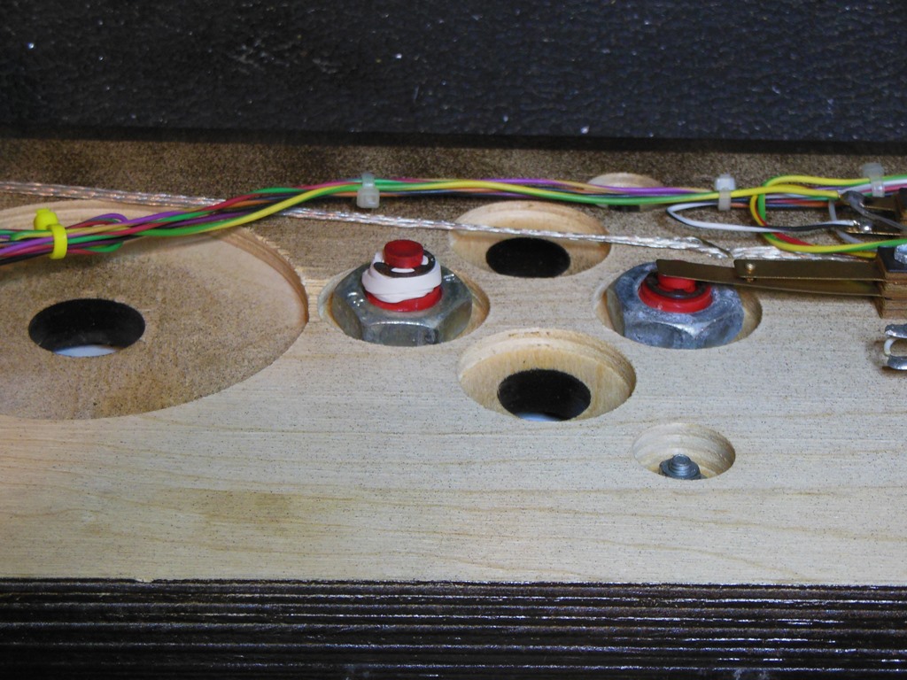
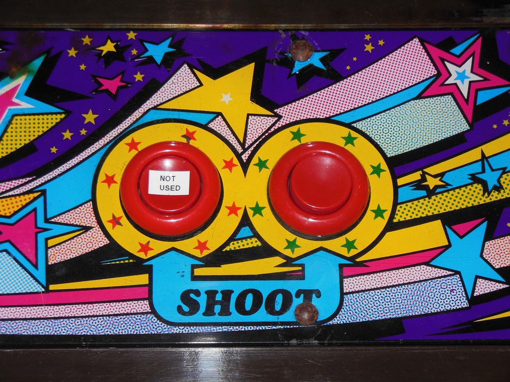
This cab had originally a single button overlay that I reused on the Mr. Do! cabinet rather than the two button overlay that's currently fitted to it. The control panel is wired only for a single button so I'm waiting on a repro of the single button overlay to be completed so that I can put a single button overlay back on this panel as it should be. In the mean time I removed the spring from a spare button, labelled it as "not used" and held it down in place with a rubber band on the back.
|
I decided in the end to fix the crease in the back of the monitor surround. The first step was to carefully remove it from the cabinet. There is a specific sequence to do this that minimizes any further creasing to the surround.


|
The steps are:

|
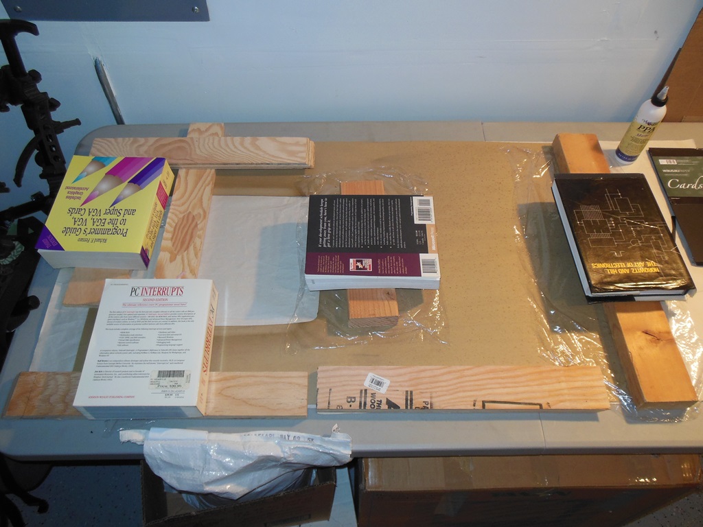
With the surround removed I cleaned the front & back with a dry paper towel first followed by a damp paper towel for the stuck on dirt (most of the dirt was dust that wipes off dry). I then used a damp paper towel over the crease area to soften the card and allow the crease to flatten out more readily and covered with a floor tile & wood pieces to keep the card flat as it dried out.
|
With the back off I decided to clean the marque light and back of the marque using a damp cloth.
|
|
|
| Full resolution | Full resolution | Full resolution |
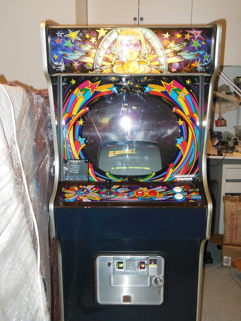
It really does have a gorgeous marque :)

|
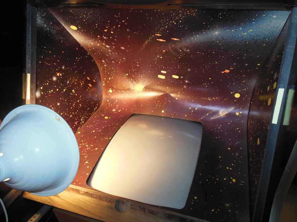
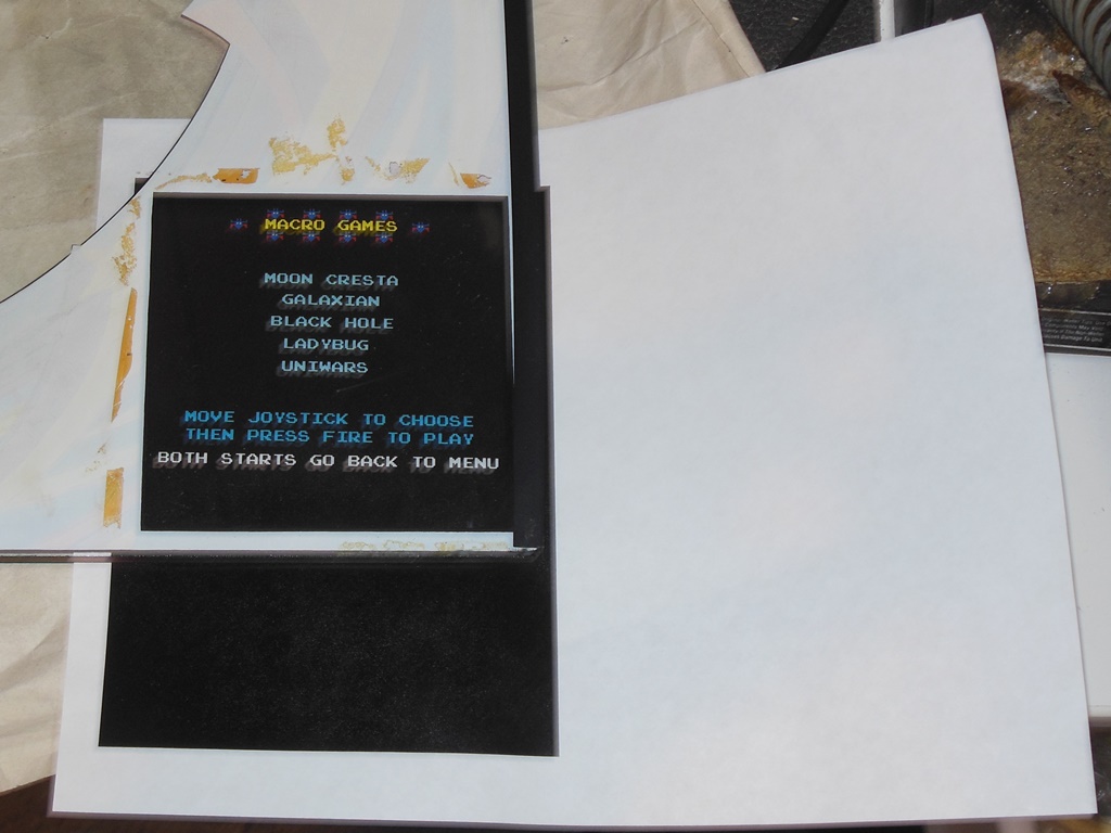
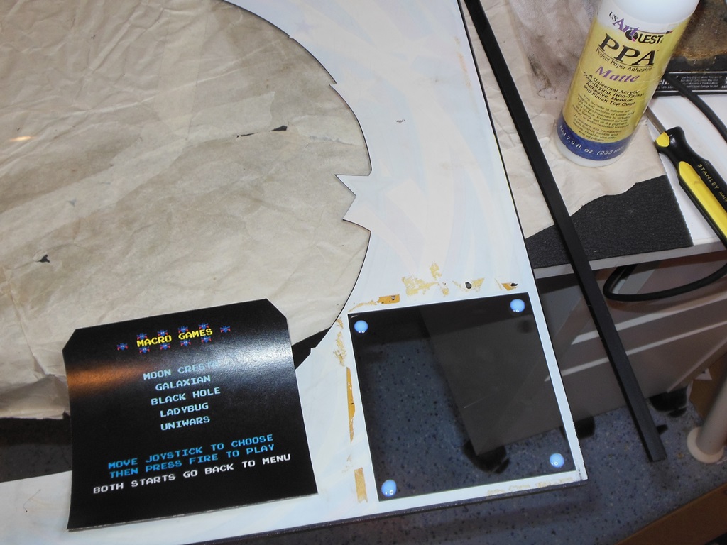
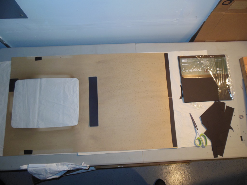
I made a simple instruction/game sheet to go behind the empty window on the monitor glass from a screen capture on Macros web site. The instruction sheet I glued onto the glass using a "dot" of glue in each corner away from the artwork silk screen. NOTE: I used far too much glue here. Only a pin head sized "dot" of glue is needed, the tiniest amount. Also note that the glue is on the plain glass portion of the window, NOT on the artwork, for ease of future removal. A small piece of IC foam and wood pieces set the sheet in place until it dried.
|
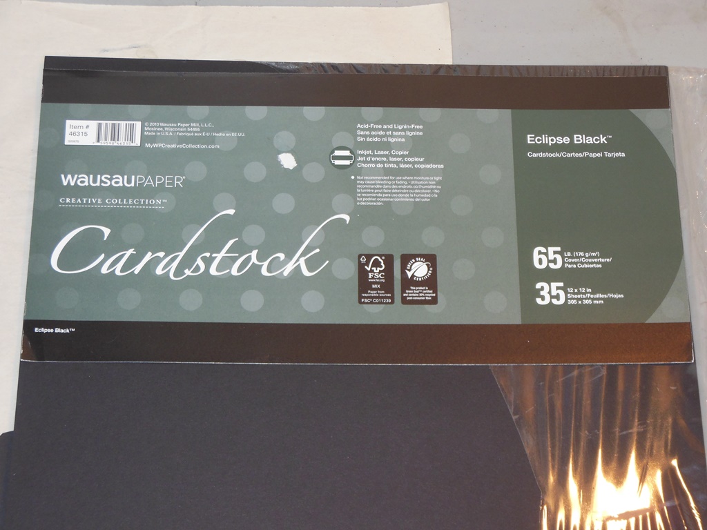
I cut out pieces of reinforcement cardboard to reinforce the staple areas, join the front tear and fix the weakened crease area. In general, small thin strips work better than large areas and in this case the strip for the crease repair was slightly too wide in retrospect. However, it didn't look too bad.
|
The procedure for refitting the surround is the reverse of the procedure used to remove it. Note that the top back panel is more easily re-bolted back in place BEFORE restapling the bottom front.
|
The final electrical work was to replace the coupled cables used for the graphics board with a single long set, remove the test socket for the CPU and fit a Dallas DS1220Y-150 battery RAM for the high score save/configuration feature. Note that when buying DS1220 modules it's important to get as late a date code as possible - there are quite a lot of Ebay sellers with photos of devices with date codes that are several years old. The ones I got were coded "1413" that means, if it follows the usual convention, that it was made in the 13th week of 2014.
|
Adding a couple more instruction labels for the show completed the game!

|
The game was still not quite 100% reliable - on cold power on the game booted into an upside down Moon Cresta with all high scores set to FF and in free play mode. P1+P2 didn't return to the game menu. I suspected an incompatibility between the game coming out of reset before the power supply had fully reached a high enough threshold to release the Dallas NVRAM out of power down. The operating power looked OK - with 5.19V at the edge connector and 5.15V on the last IC on the multigame. I decided to replace the existing reset capacitor on the game board with a larger one to extend the power-on reset time. The Midway schematic showed 10uF though this board was fitted with a 47uF that I replaced with a 100uF value (doubling the reset time).
|
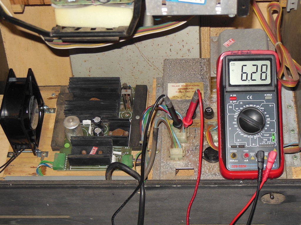
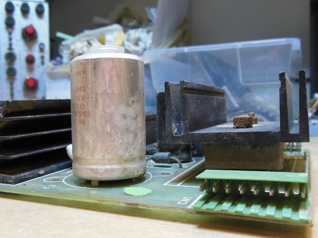
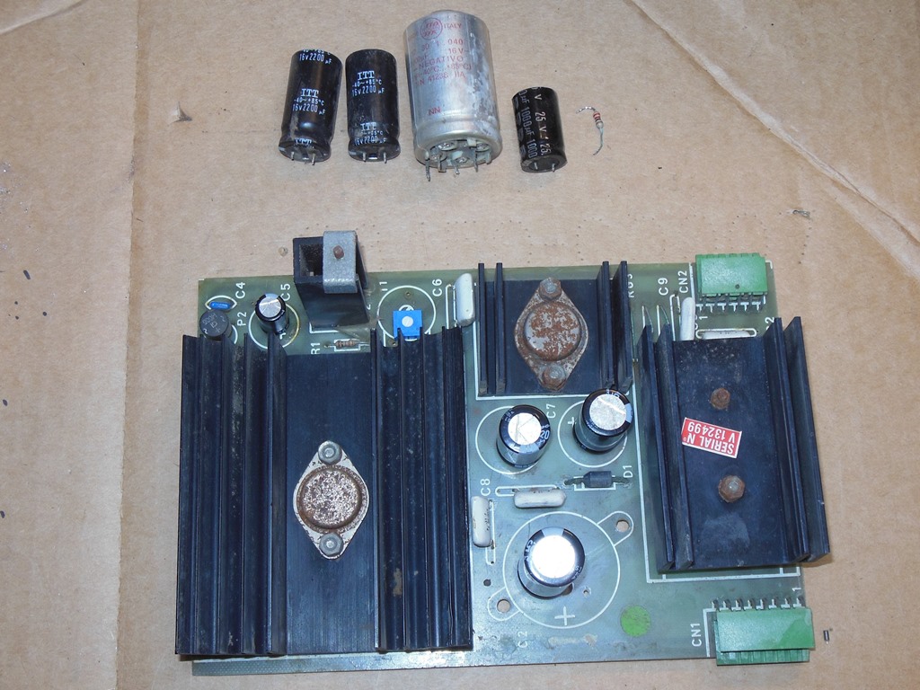
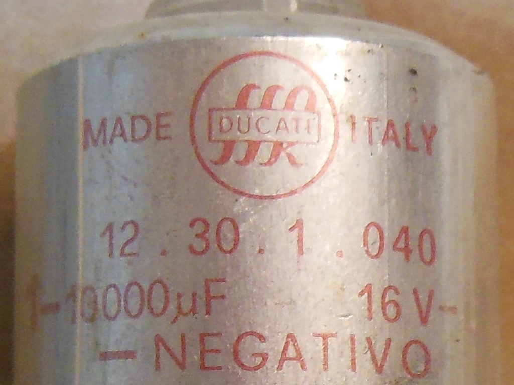
During long term testing the game was resetting and clearing the NVRAM. Over a four hour period it reset & lost settings twice. Attention once again turned to the power supply. DC voltages looked good still but it was time to check the smoothing. Measuring the AC ripple didn't show anything significant, however when the 5V smoothing capacitor was gently squeezed the AC ripple reduced by a about a quarter. The capacitor, an unusual silver Ducati 10,000uF, was showing signs of leaking & resultant corrosion. I decided to cap kit the power supply board (that also adds the voltage adjustment pot option). After the cap kit the 5V AC ripple was much less and the crashes stopped.
|
During pre-show testing the game lost picture. The game board had power and the monitor HV but there was no picture and no coin up so I suspected a board issue. Pulling out the board and investigating on the bench confirmed no video output at all from the board. Poking around with a scope revealed no activity on the CPU address/data bus that was due to the CPU RESET line stuck low (active). Tracing the stuck reset line back found no clock on pin 1 of 6T (LS393). The VBLANK line was inactive. This was traced back to no video count out of 5A & 6A (LS161). Tracing back down the counter chain found 3A pin 2 showed a healthy 6MHz input but pins 11/12 were idle, 13/14 running and the carry output on pin 15 idle. 3A had been replaced before in the past and was already socketed (and also chipped). Replacing 3A (LS161) fixed the game.
|
After resuming pre-show testing for the second time, after an hour or so the game lost all graphics except for the stars. Pulling out the board (again) and investigating on the bench found pins 6,7,8 (A0-A2) were idle out of the character EPROMS (2716). Working back found pin 1 (CLR) of 2M (LS273) OK but pin 11 (VPL) idle. Inspecting 4D (74139) revealed pins 15,14,13 active and 12,11 idle. Pins 6,7 also looked bad. I suspected 4D was bad and replacing 4D brought back the characters. This was another IC that had been changed before and that prior replacement had damaged a number of pads that needed further tracing & rework to fix :(
The 3rd attempt at pre-show testing went OK and the game ran without any further issues for a few hours.
Finally in the show for the first time, the game board started to develop problems with the shells and missiles on the first show day. By the last show day the missiles had disappeared entirely and the shells were not working properly. Further, the sprites had lost a colour bit. Despite those issues Moon Cresta was still getting a lot of play.
Starting with what I suspected would be the most difficult problem to find, the bad shells & missing missile.
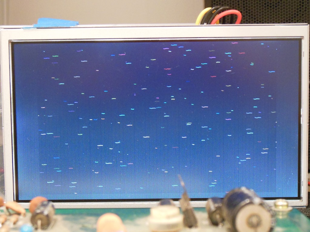
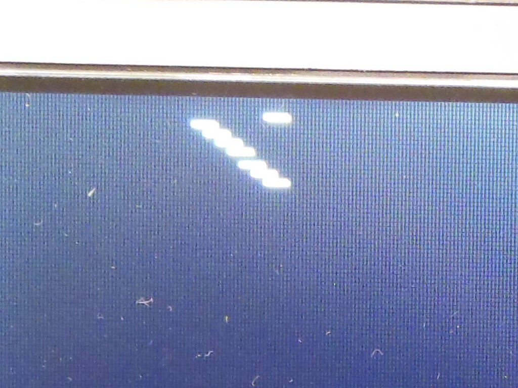
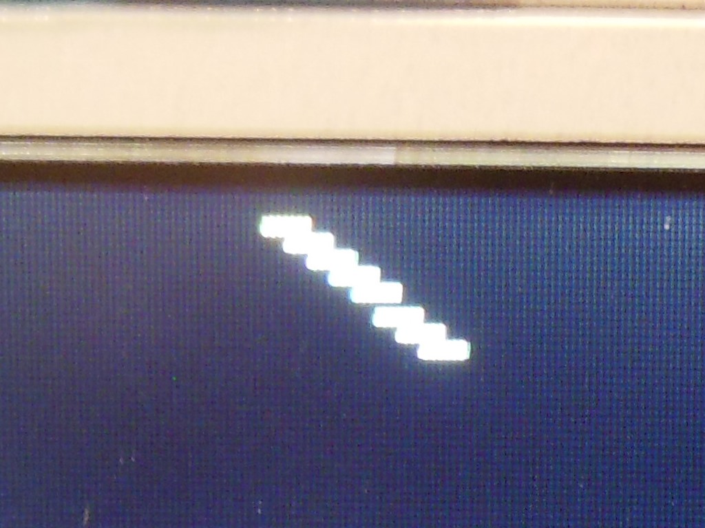
It quickly became clear that trying to fault find the shell/missile problem was going to be very difficult in game mode - they are only used in the game portion of attract mode and effectively random & short lived on screen. What was needed was a specific test that would drive the shell/missile hardware in a constant & deterministic way so that the exact nature of the problem could be seen. To that end, I added a "custom" function to the Arduino ICT that programmed all seven white shells and the single yellow missile to sweep diagonally across the screen. The timing for the sweep is one XY pixel increment per VBLANK interrupt. They are spaced one pixel apart to make them easier to see and the slight shift between the bottom three and top four shells is a positioning difference that's a normal part of the hardware.
As can be seen from the video above, the shells appeared to be working properly in this test but the missile was missing and replaced by an extra shell in the wrong place.
|
It looked like the shells were actually working properly but something was wrong with the missile. Since the handling for shells and missiles is mostly common, this narrowed down the source of the problem to something specific to the missile. Poking around with the scope showed that MLD (missile counter load) had a sharp "V" low pulse to ~3V instead of a full length low signal. Attention turned to 4C (LS139) and 3C (LS20) that make up the circuit for selecting MLD versus SLD (shell counter load).

|
Setting up both channels of the scope to better verify the timing relationship between the latched common MSLD signal and the missile selector out of 3C showed that the inputs to 4C seemed OK. Changing 4C (LS139) brought back a good SLD signal on the scope but the display now showed the correct seven shells alone but still no missile :(
Tracing forward from the now working SLD signal to the missile position counters 5R & 4R (LS161) found no life out of 5R, the 4th LS161 on this board to fail. Replacing 5R (LS161) finally fixed the missile.
|
During retest the video lost synchronization. Now keenly aware that the LS161's on this board had been repeatedly failing I immediately looked to the last remaining original LS161 in the video counter chain. I wasn't disappointed - the scope showed that there was no carry out on pin 15 of 4A (LS161) and a couple of the outputs looked erratic. Replacing 4A (LS161) fixed the sync.

|
Attention turned to the missing colour in the sprites. Looking at the outputs of the sprite RAM found that the DI input to 1N (27LS00) looked OK but the output DO was always floating. I didn't have any spare 27LS00 RAM to swap in so I needed to search through a box of old bootlegs to find something that looked equivalent. I found a cocktail bootleg populated with 82S16 that looked to have the exact same layout as this board. Replacing 1N (27LS00) with an 82S16 brought the sprite colours back but there were still some shimmering lines through the sprites when they passed into the lower half of the screen.
Using another 82S16 to replace each of the remaining sprite RAMs in turn fixed the game when the RAM at 1T was replaced. Swapping the suspect RAM into a different position (to eliminate a bad socket as a cause) confirmed that the RAM at 1T was bad. Replacing it with a 2nd reclaimed 82S16 finally completely fixed the game.

|
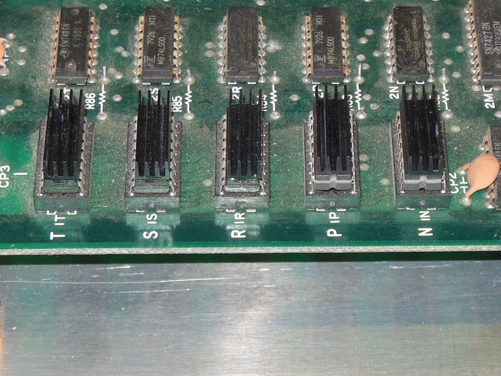
I found a small bag of DIL heat sinks that I decided to fit to the sprite RAM as was done on other editions of the PCB (e.g. the Midway one). Fitting the heat sinks was straightforward - clean the IC top and the heatsink bottom before gluing in place.