
This game was spotted in a jukebox warehouse in Vlaardingen, Holland by members of the Dragons Lair Fans forum in 2011. With assistance from the forum folks I was able to acquire the machine and a friend in the UK was able to keep it for a few months until it came to the US as part of The Big Move the following year.
It wasn't clear what game the cabinet might have been used with - the game board was missing and no instruction card was fitted. The cabinet itself looks like it was barely (if ever) actually operated with the sides still partly covered by the original factory protective film.
|
|
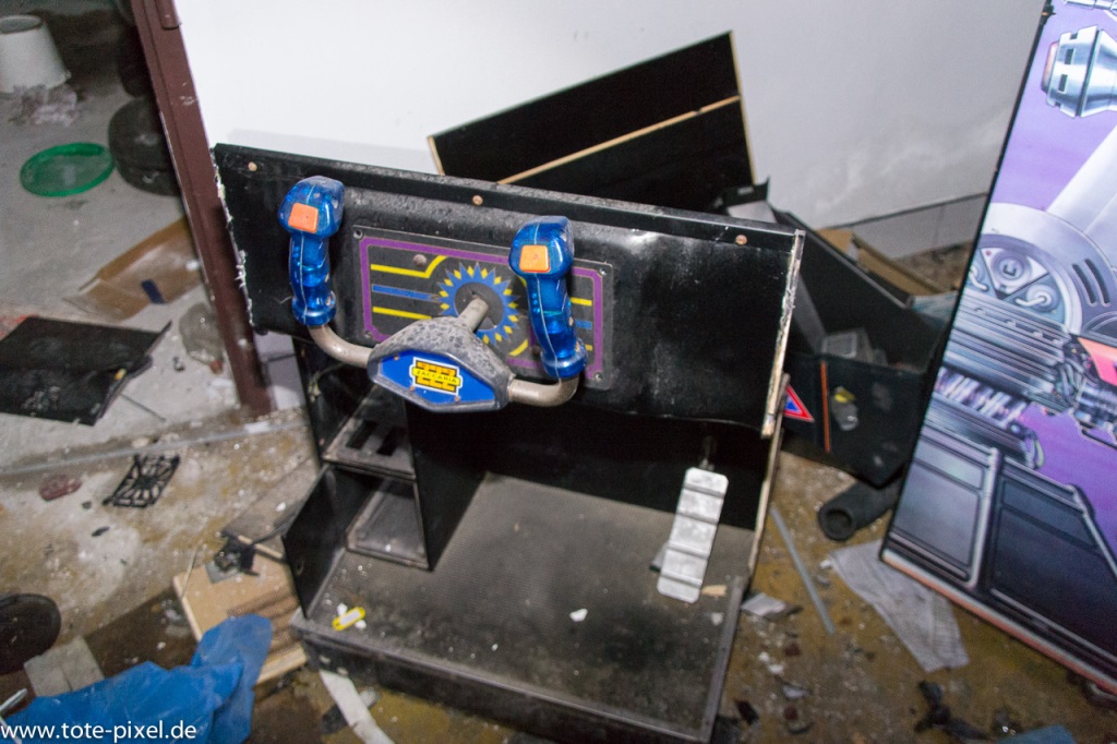
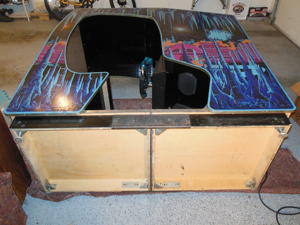
This is the picture of the cabinet as it was found in the Dutch warehouse.
|
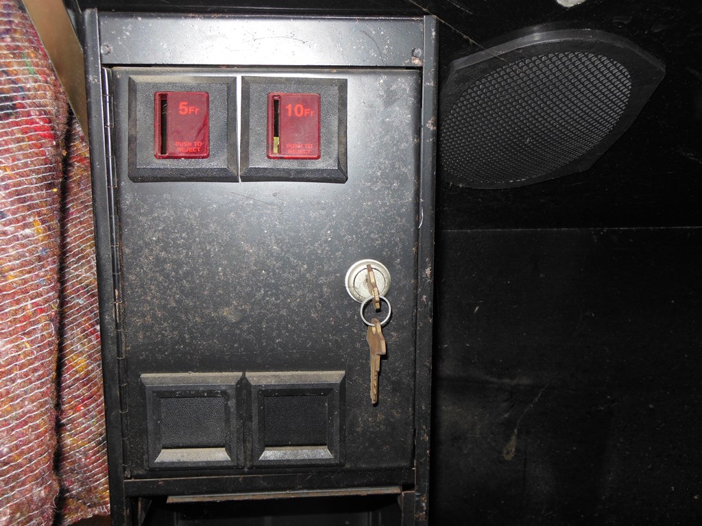
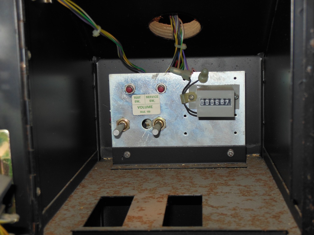
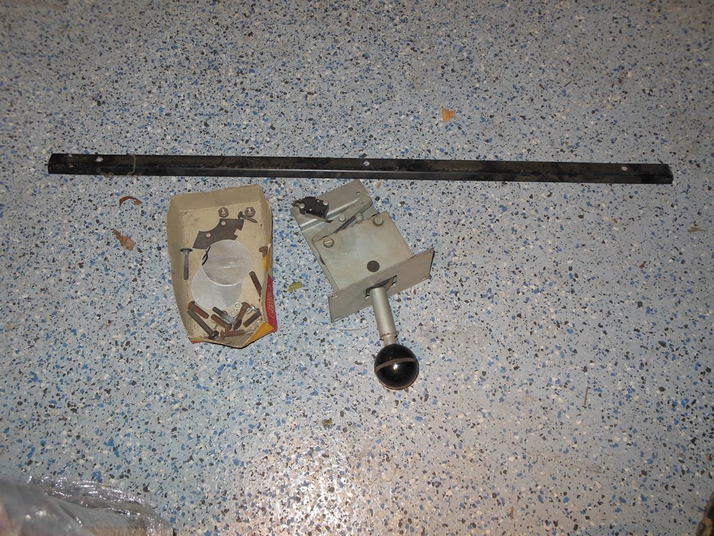
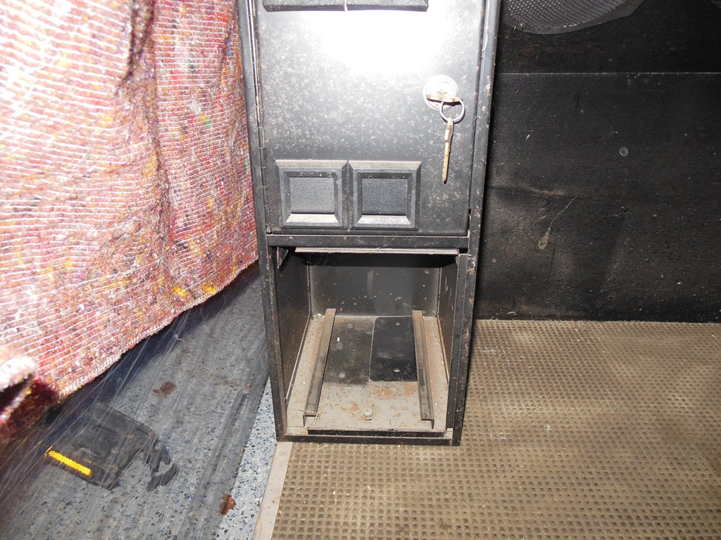
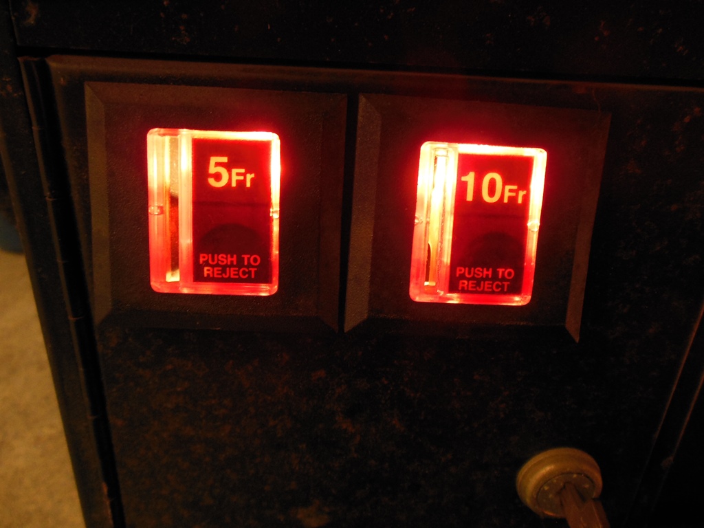
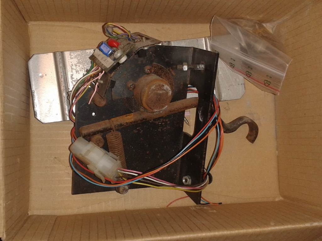
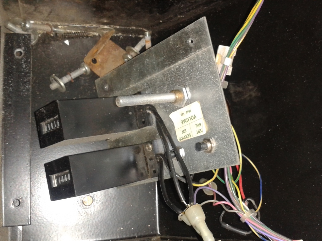
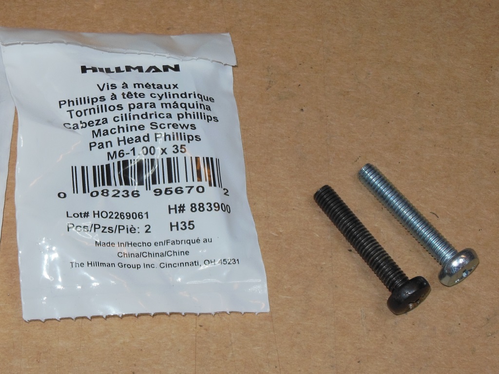
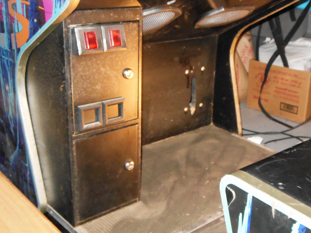
The back door is missing but the coin door had the original ZZZ logo keys in it. The cabinet unusually includes service controls behind the coin door comprising test & service buttons, twin volume controls and the coin counter showing 687 credits. In the bottom of the cab was a small box of assorted screws & other metalwork along with a gear shifter and metal strip that I suspected was from the monitor glass that was undone.

|
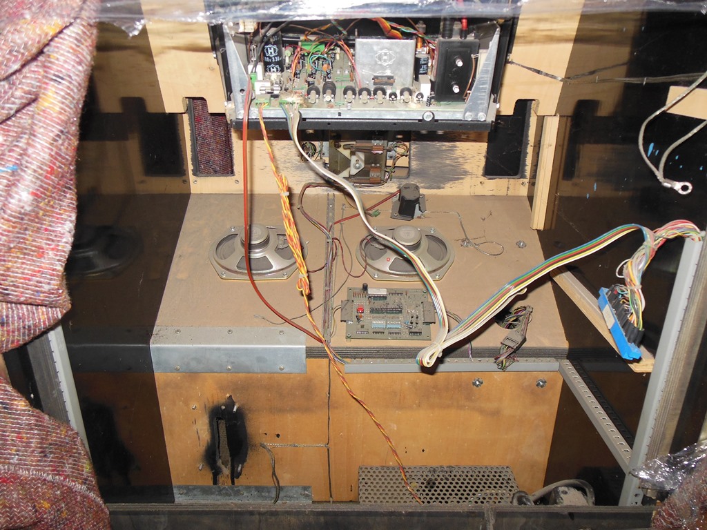
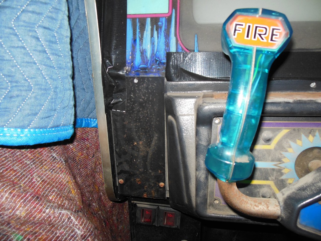
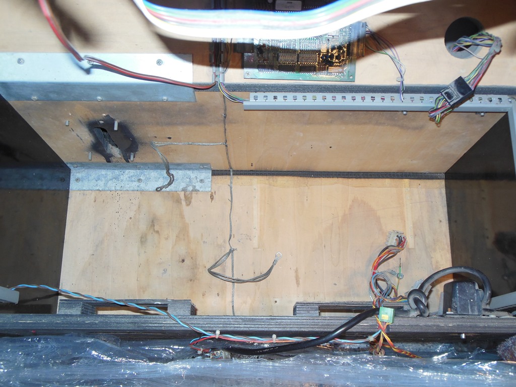
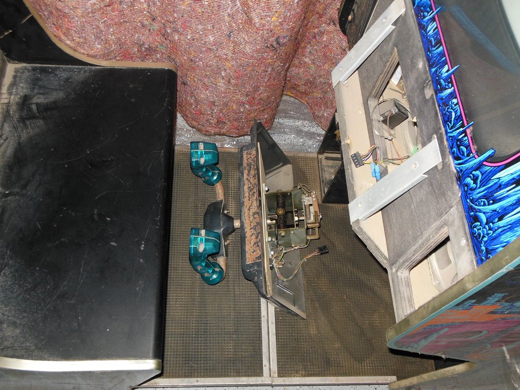
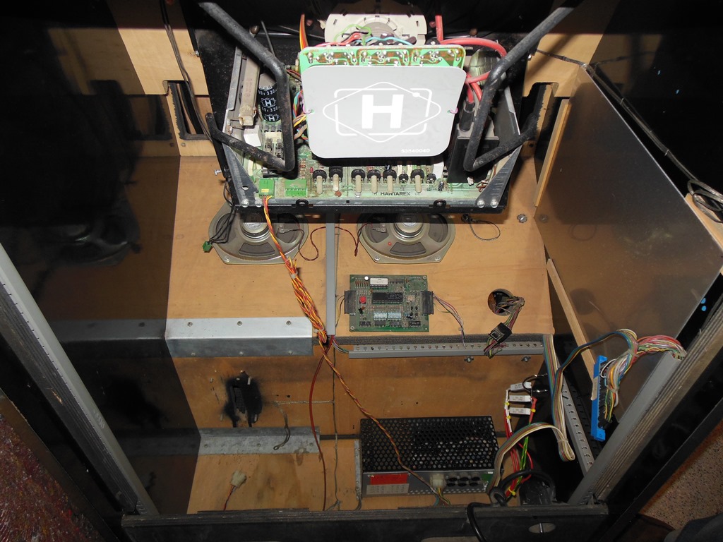
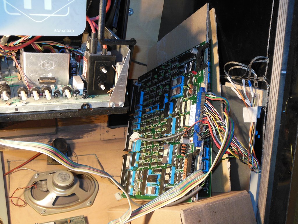
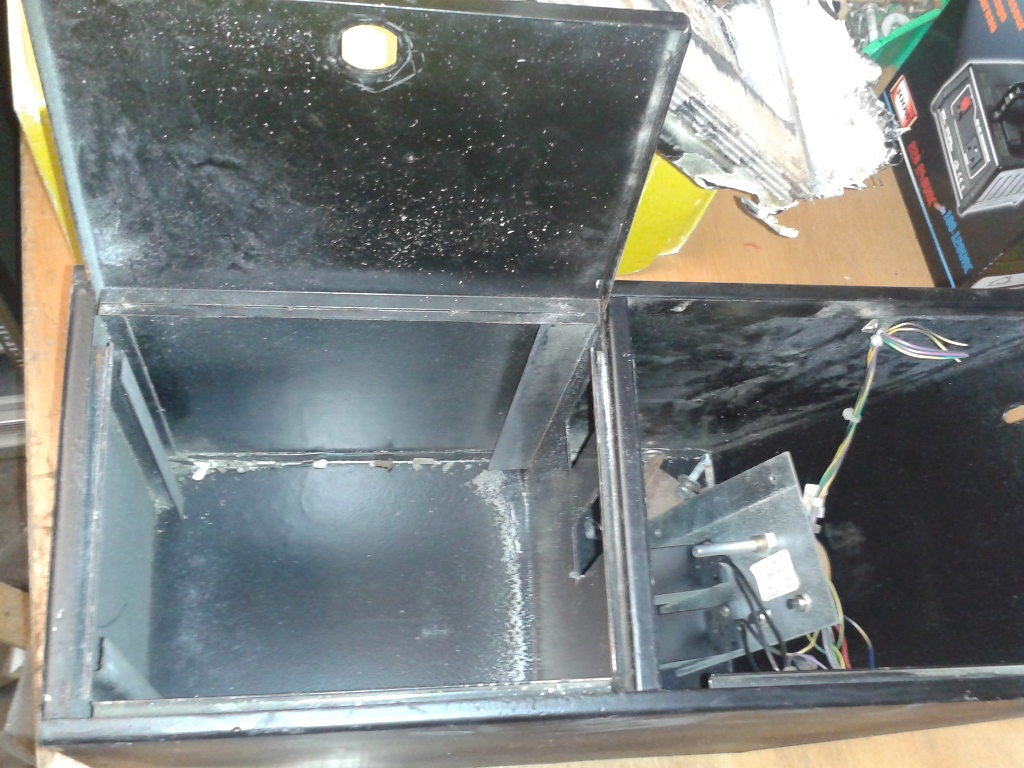
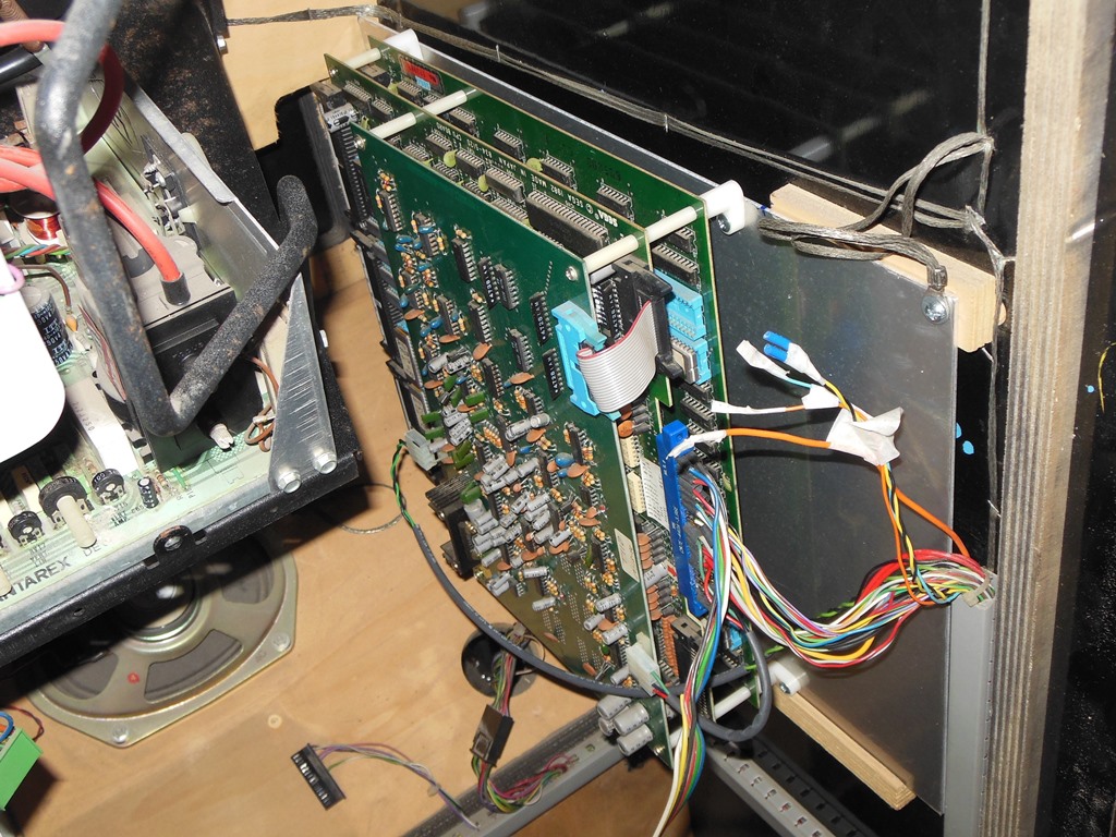
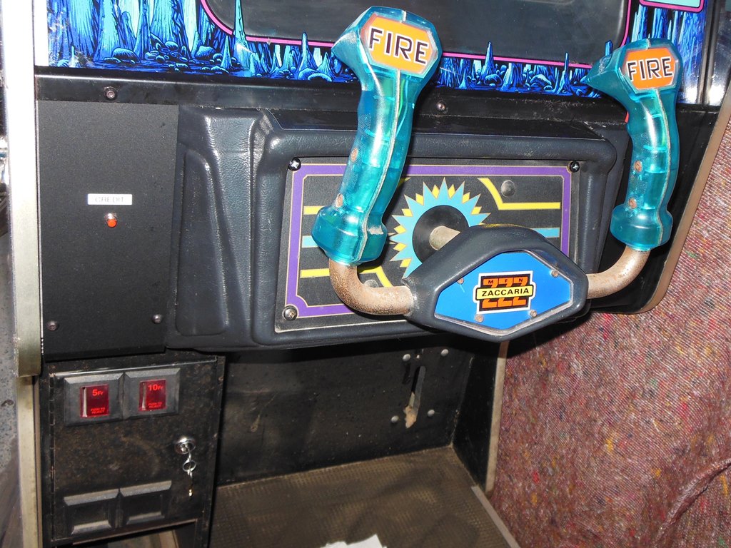
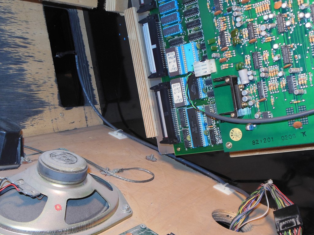
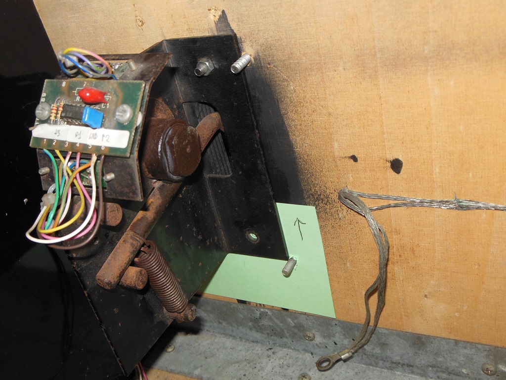
Inside the wiring looked mostly original and complete. On the back of the flight yoke a small 2-pin connector had been added. It also looked like the yoke opening had been widened on the left showing the start button behind based on the paint spray. There are factory openings on the right & left of the control panel but no factory wiring and an opening in the base for a foot pedal that does include factory wiring. The screws for the pedal were still present suggesting that a pedal was present originally. The back had been left open a while and had served as a bird roost - there was guano piled in the bottom of the cabinet and assorted deposits over the monitor chassis.
|
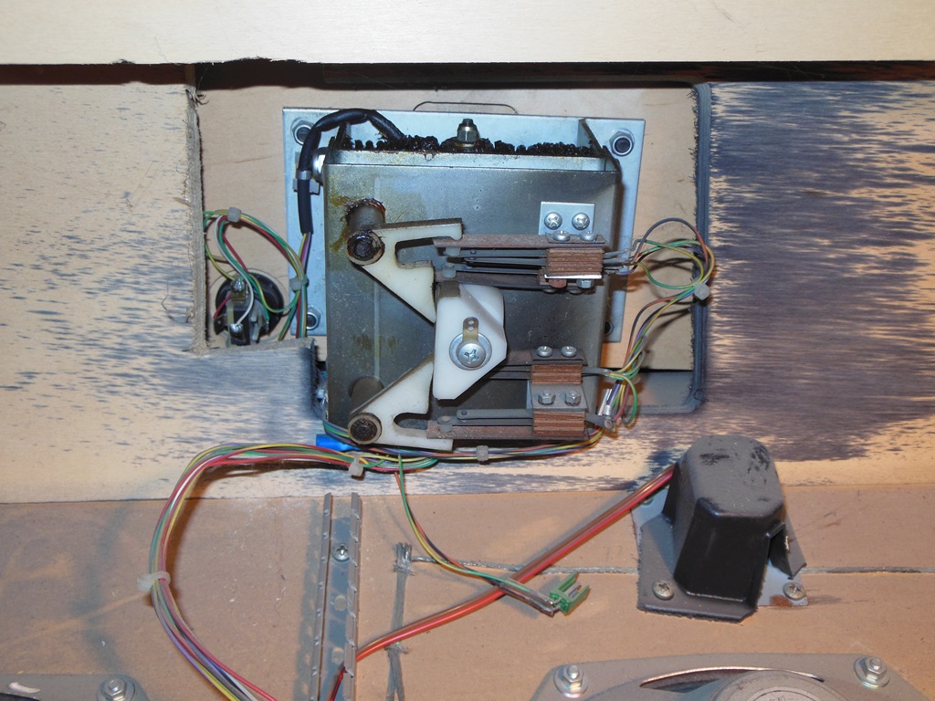
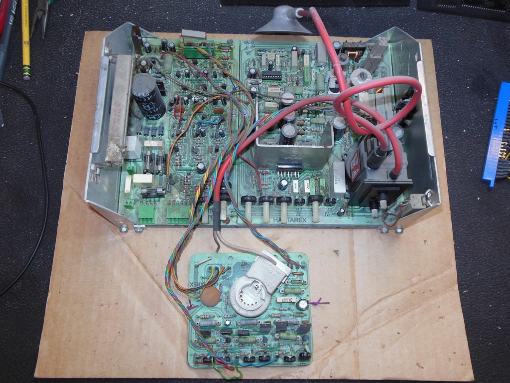
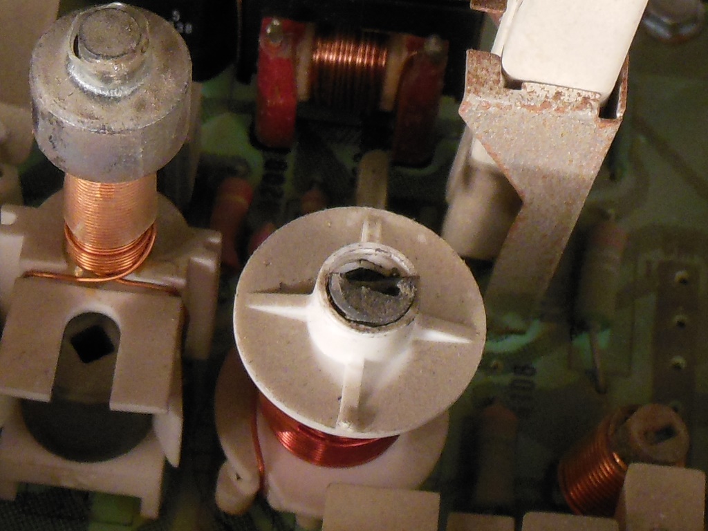
The guano on the Hantarex MTC-900E monitor chassis had caused some components to be corroded and at least one fly wire had snapped off as a result.

|
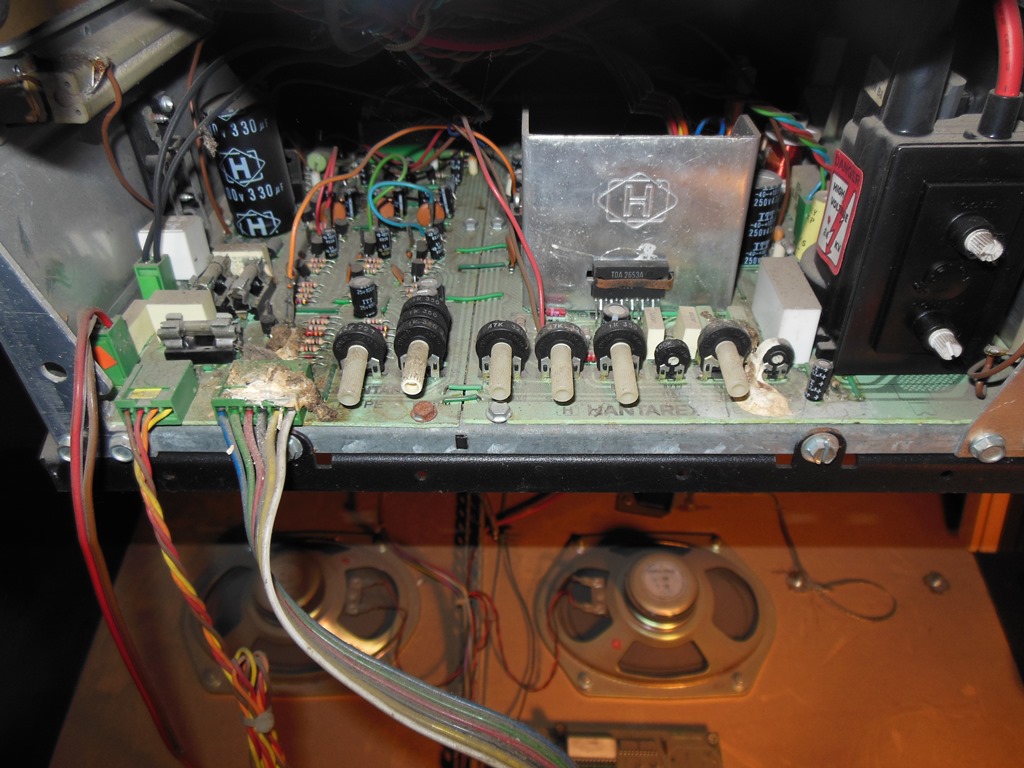
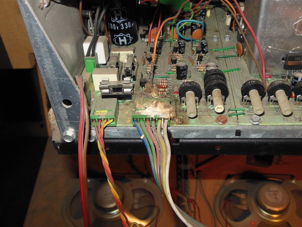
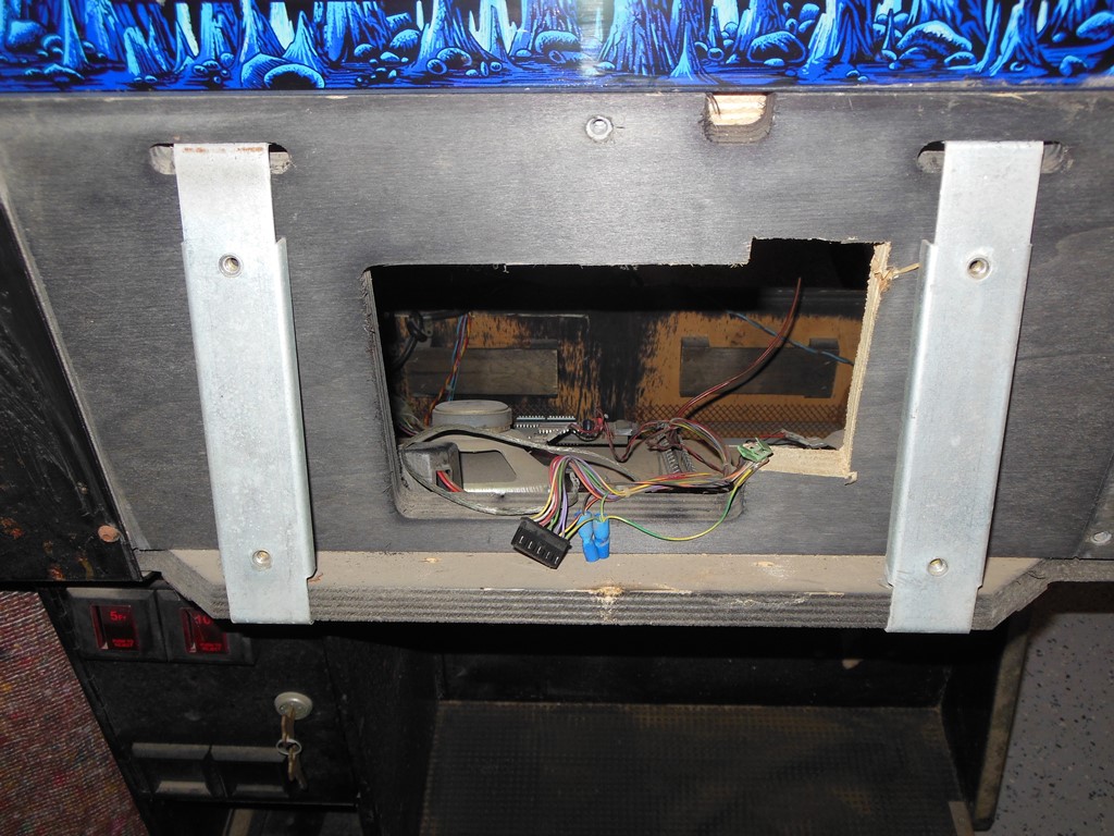
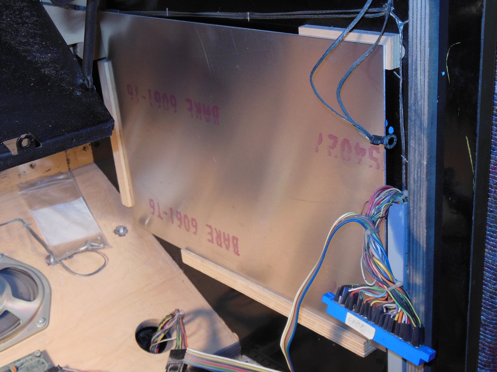
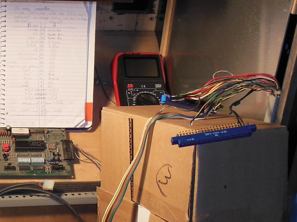
The game board was missing and the edge connector for it was not labelled other than "comp" for component side. The game the cabinet was wired for was unknown though the solder on the unused pins suggested that the pinout may have been changed from the original factory pinout.
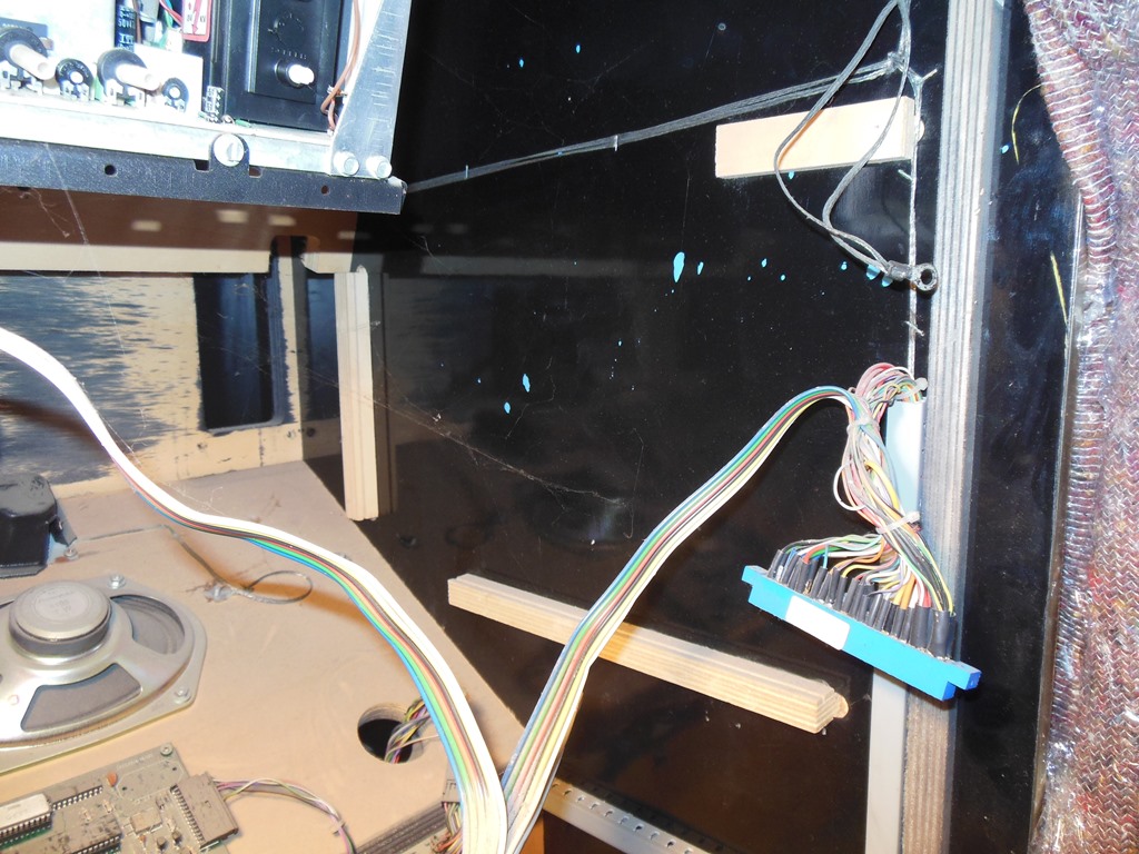
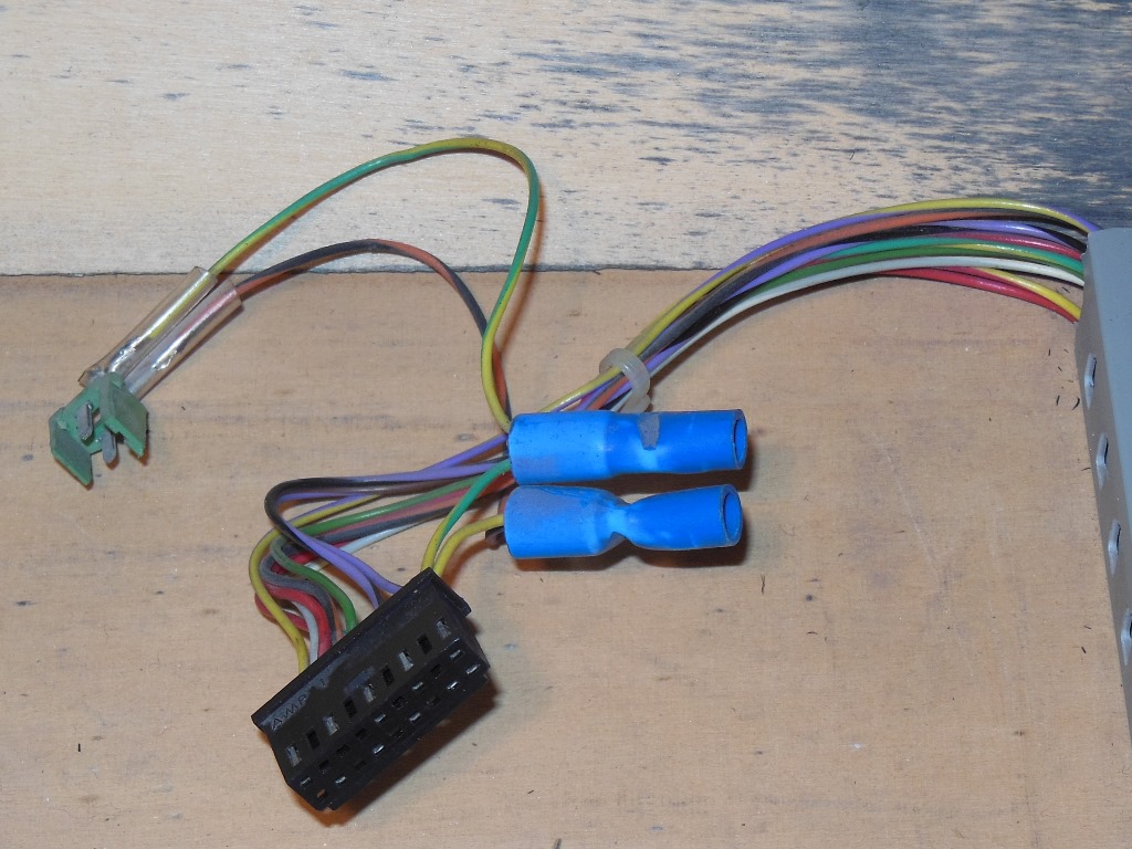
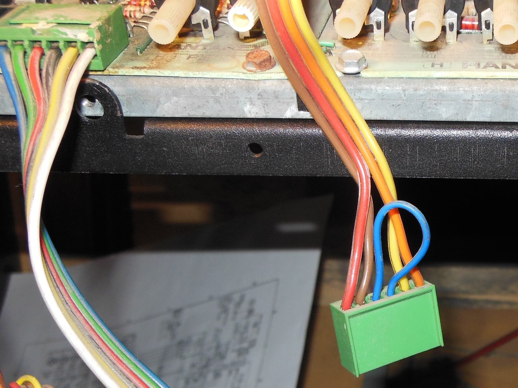
The empty slot wired for a foot pedal has GND (black), +5V (red) and two other pins. (blue & orange) There was also a 2-pin connector "hacked" in behind the control panel. U/D/L/R are digital inputs from the dual handled flight stick sort of contraption (the same thing that's on Buck Rogers) and there is a trigger fire button on each handle. Using a multi-meter I worked my way through figuring out the connector wiring:
-------------------------------------------
         Comp. Side B |    | Solder Side A
----------------------|----|---------------
       Speaker Left - | 22 | Speaker Left +
                    - | 21 | Speaker Right -
                 Coin | 20 | Speaker Right +
                Green | 19 | Sync
                  Red | 18 | Blue
                    - | 17 | -
   Foot Pedal "blue"  | 16 | -
  Foot Pedal "orange" | 15 | -
            Fire Left | 14 | -
           Fire Right | 13 | -
                 Left | 12 | -
                Right | 11 | Test
                 Down | 10 | Service
                   Up |  9 | -
                Start |  8 | -
                 -12V |  7 | -12V
                  -5V |  6 | -5V
                 +12V |  5 | +12V
                  +5V |  4 | +5V
                  +5V |  3 | +5V
                  GND |  2 | GND
                  GND |  1 | GND
----------------------|----|---------------
- No connection
There were multiple connections to a number of the power & ground pins that reflect the routing around the cab to various other places. Most notably the start lamp was wired to +5V and thus would be always on and I'd need to separate the individual wires out to find it.
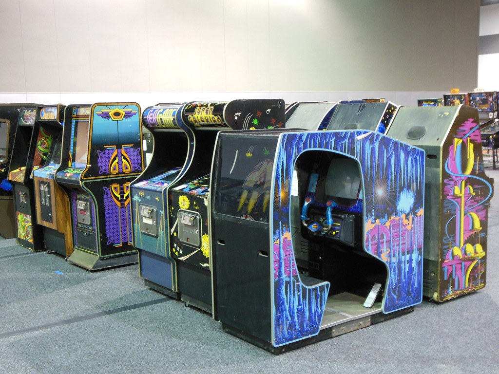
Looking around the internet at a number of different pinouts and a few shout outs on various forums yielded no leads on a matching game for this pinout. Further, the 4-way yoke, single start button and horizontal front facing monitor narrowed the choice of compatible games to near zero. As far we could determine, despite being a universal moniker cabinet only Buck Rogers naturally fits in its factory form. The conclusion was to try to put Buck Rogers in the cabinet but I was missing one significant piece - the foot pedal - entirely :(
|
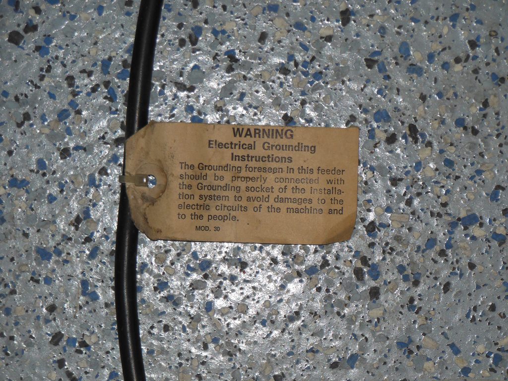
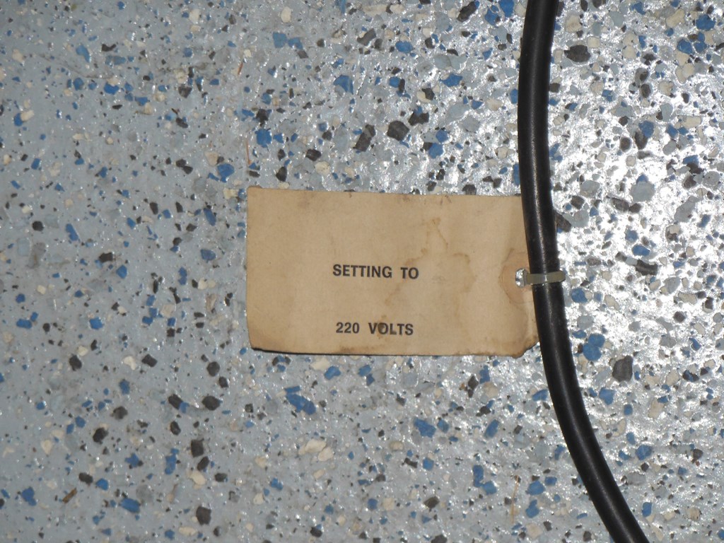
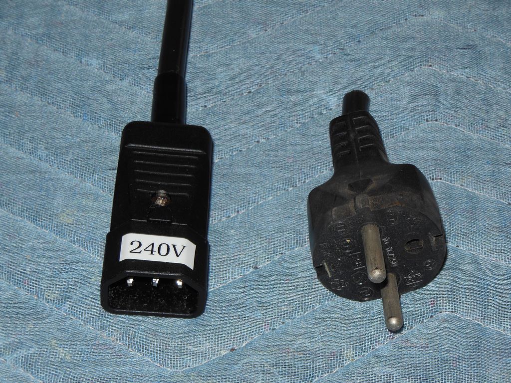
The power cable still had the voltage warning label attached and I changed over the power plug to the usual IEC-C14 style I'd been using for native 220V-240V powered games. I didn't power on before first going over the IGR power supply and monitor chassis to remove all the guano and make any repairs first.


|
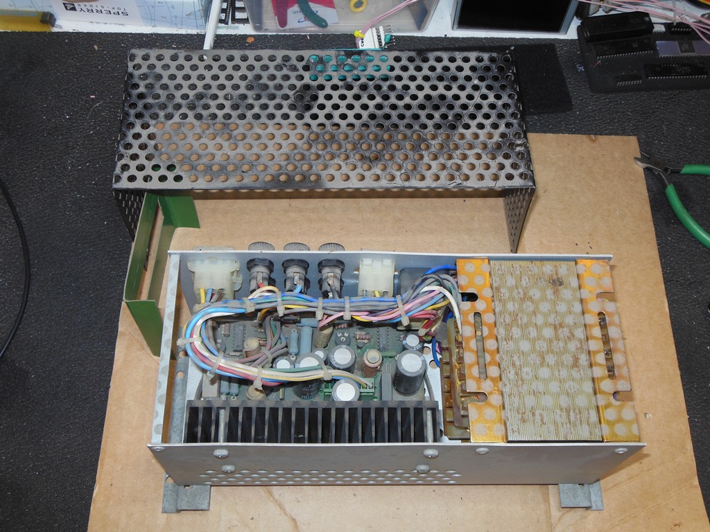
The IGR elettronica M1010 power supply was in excellent condition. The labels were pristine and suitable for making reproductions if needed.
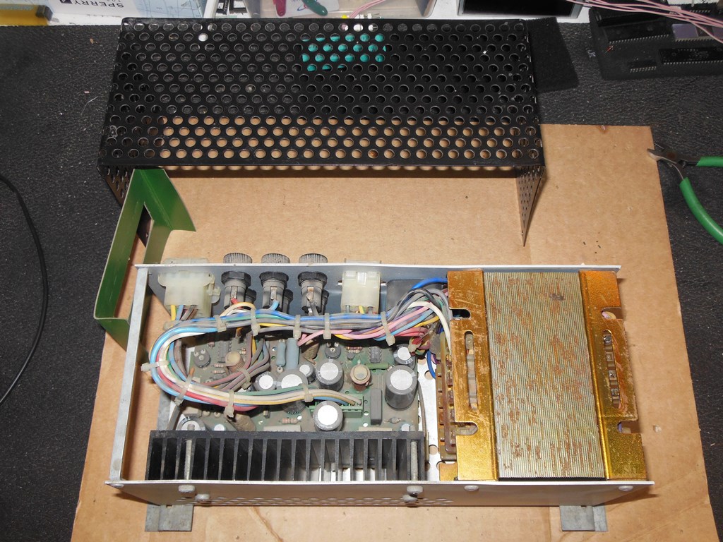
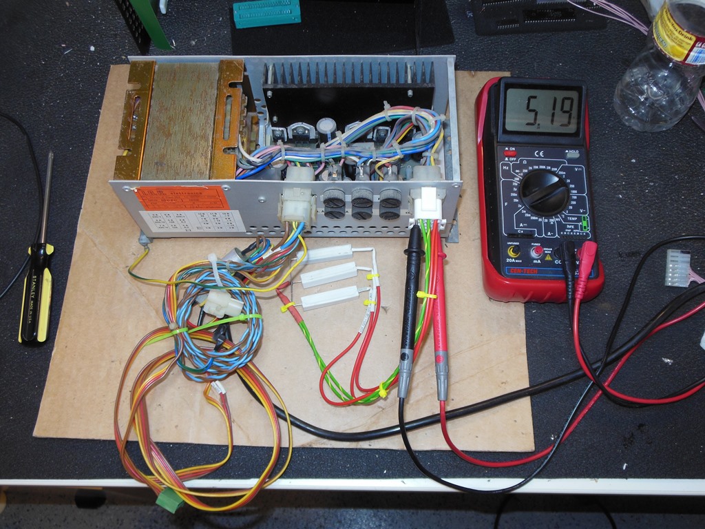
|
The IGR power supply only needed a blow out with the an air duster and a wipe with a cloth to clean it up. None of the guano had got inside. Testing on the bench showed it was working fine and it ran with a dummy load for several hours without issue.
A video was posted on the Dragons Lair Fans forum showing the remains of a severely
vandalized arcade collection in Germany (a.k.a the "Vossen" arcade):
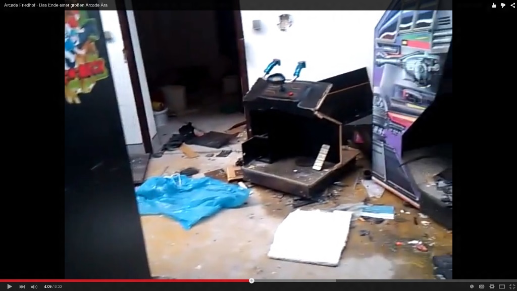
|
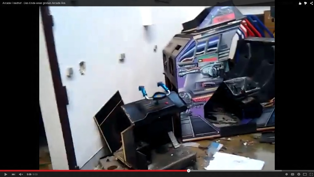
There in the distance at 4:09 and close up at 5:09 can be seen what remains of a Zaccaria Buck Rogers cockpit :(
|
Several people on the Dragons Lair Fans forum lived near enough to be able to visit this place and save what they could from what's left. In my case my cockpit needed the Buck Rogers foot pedal, cash box door, control panel molding and metal strip along the top that keeps the monitor glass in place. The instruction cards from the monitor glass and the large clear back panel marque for Buck Rogers seemed long gone but those could be reproduced.
|
|
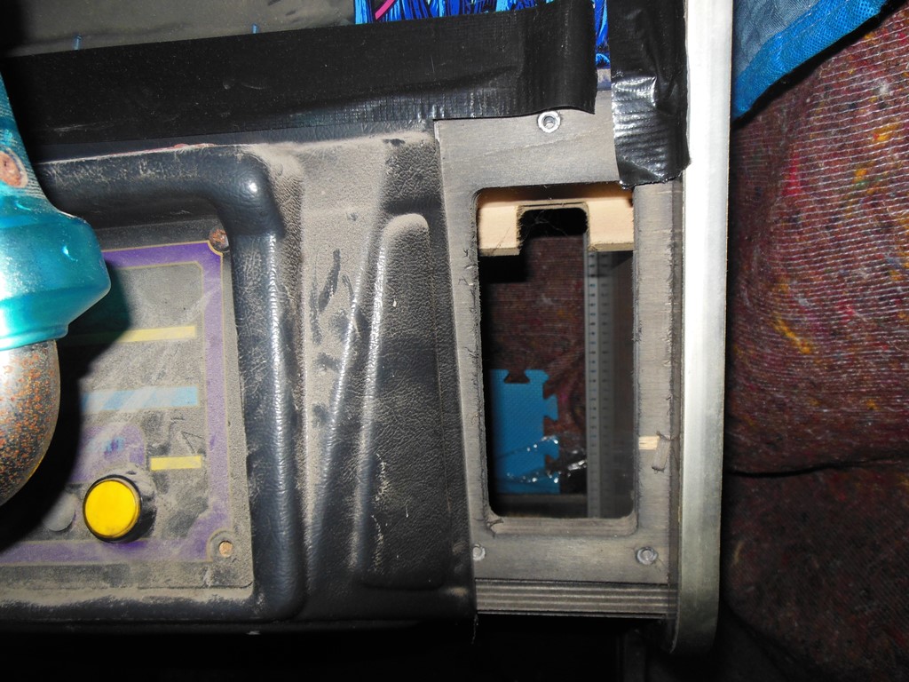
My cabinet had a different control panel molding with two blanking plates on either side that covered optional cutouts for additional controls. On the left there was a home made looking blanking plate and on the right the blanking plate was missing. The Buck Rogers control panel molding is different and covers the full length with no blanking plates (the factory Buck Rogers cabinet has no cutouts).
|
I vacuumed and cleaned out all the guano & dust from the inside of the cabinet. The monitor glass was taped down prior to the original shipping of the cabinet out of Holland and could now be removed and the glass cleaned. The glass itself is in good condition with only minor peeling.
|
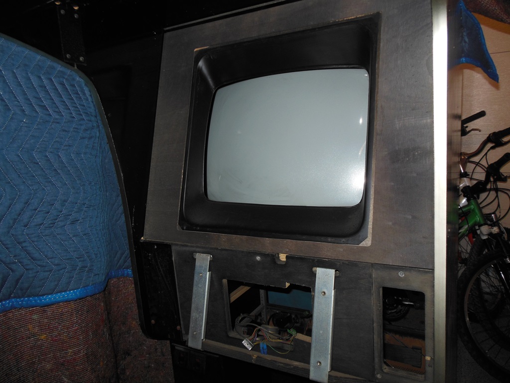
I removed the control panel in order to remove the monitor glass for scanning. The cabinet has a molded inner surround around the CRT set into a square cutout in the frame that thus allows the monitor to be used in either horizontal or vertical. Similarly the monitor glass has square artwork to match.
|
|
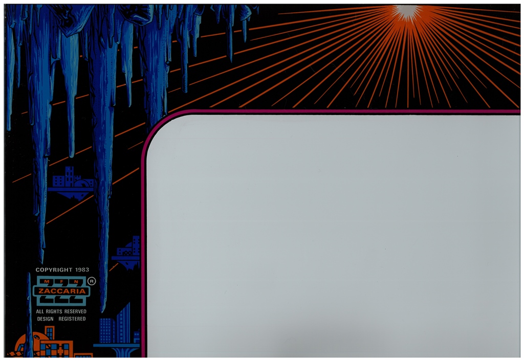
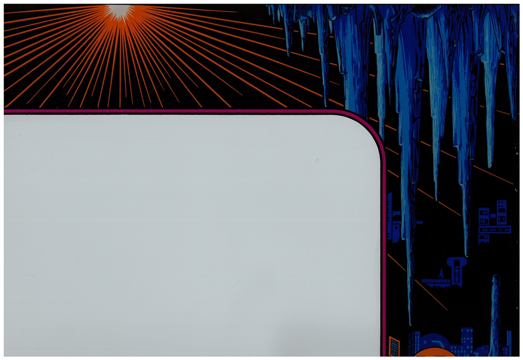
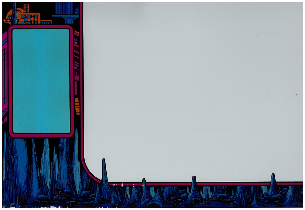
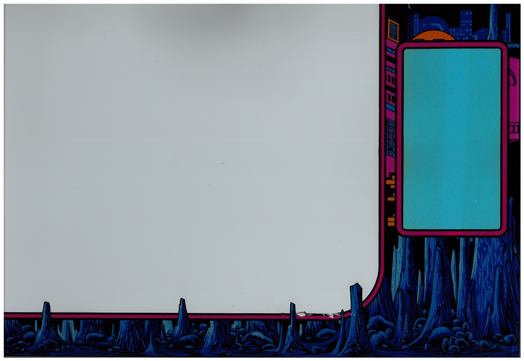
Scanned in the Universal cockpit monitor glass.
300 DPI Universal cockpit monitor glass scan (22.2MB).
|
Of the two batches of "repro" PCB mounting plates I had previously ordered from OnlineMetals, the first batch that were a little too small for some boards fitted perfectly in this cabinet. The second batch that I ordered larger to be able to accommodate Galaxian-sized boards were too long to fit in the cockpit cabinet.
I also noted that the PCB mounting hole in the cabinet appears to have never been used - there is only a single unused pilot hole.
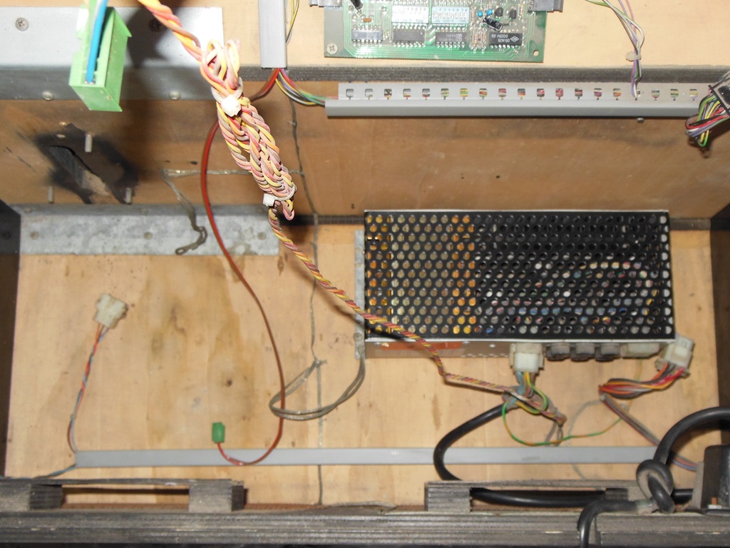
The IGR power supply was fitted back into the cabinet ready for testing.

|
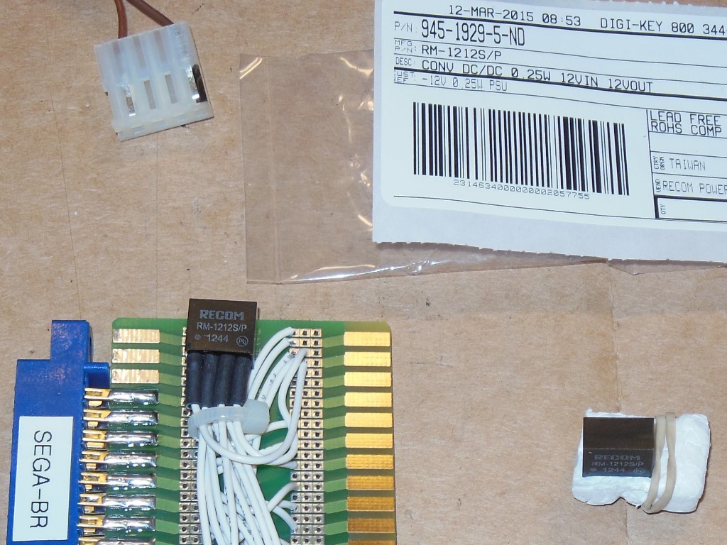
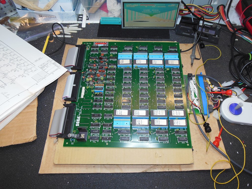
I had one complete but untested Sega Buck Rogers PCB as a candidate to go in this
cabinet. In order to test it and fix it I needed to make a JAMMA adaptor for it but
there were a couple of complications to account for:
|
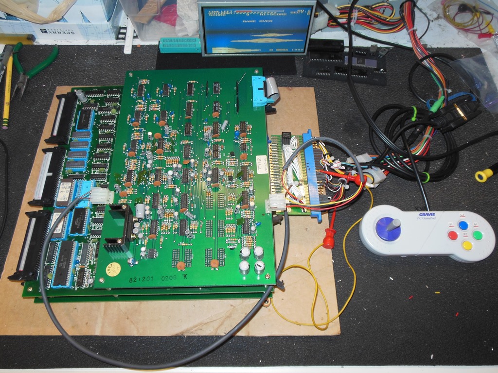
On the bench the board set was mostly working and playable. The major obvious issue to address first was that the sprites seemed massively over scaled (zoomed up). Since most of the sprite scaling hardware is on the "EPROM" board the board pack needed to be separated, the audio board removed and the EPROM board flipped over to the top. Jumping in with a scope quickly revealed digital data going into the uPC624 (== DAC08) but no life on the analogue output. Removing the uPC624 had no impact. Alas, I had no spares of either uPC624 or DAC08 to try so further PCB fault finding would have to wait until replacement parts arrived.

|
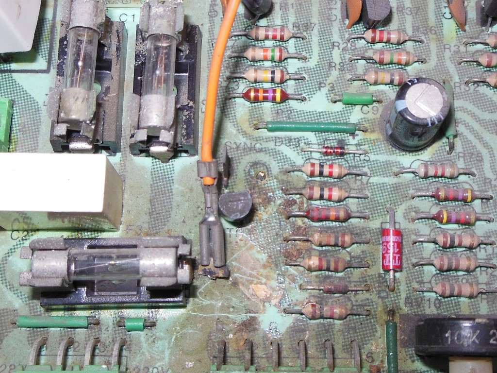
The guano that was on the chassis had corroded one of the mini-spade connectors that had then snapped off. A close (but not exact) equivalent replacement exists (Keystone 1267K) and I'd used them before to replace broken spades on other Hantarex chassis.

|
The remaining components in this area were similarly dirty and corroded but hopefully not significantly compromised.

|
With the chassis repaired it was time to power up the cab for the first time. I fitted a dummy load to the IGR to keep it properly loaded in the absence of a useable game PCB.

|
Power on yielded no issues and was as expected - the coin door lights came on, the fan started and ran properly and the monitor came on with a steady blank raster :)
|
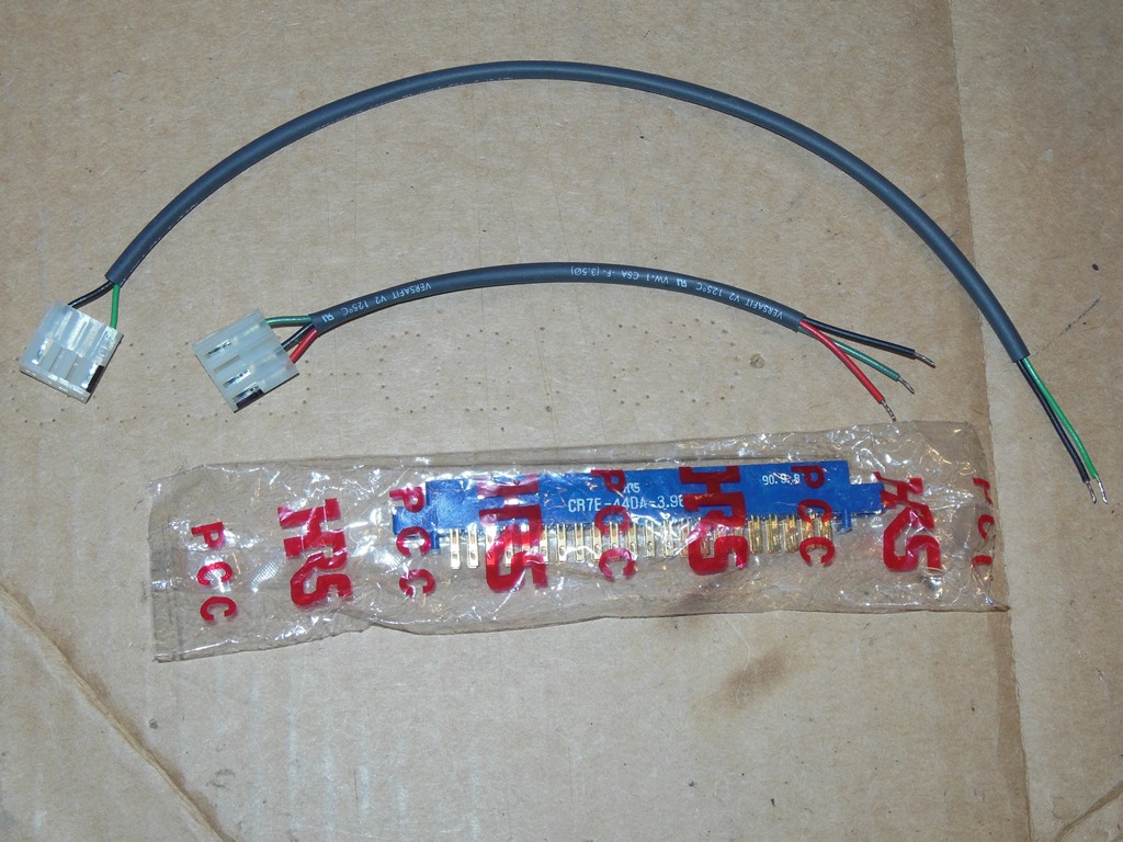
I assembled the two separate sound board connectors in advance for ease of fitting and then began rewiring the cabinet to Buck Rogers. It wasn't the most comfortable working environment with the cramped cockpit interior low to the ground. For the most part the wiring is the same as the Sega cockpit Buck Rogers wiring in the Sega manual but there were some Zaccaria cockpit specific differences noted below:
---------------------------------------------
         Comp. Side B |      | Solder Side A
----------------------|------|---------------
             Vid. GND | Z 22 | Blue
                 Sync | Y 21 | Green
                    - | X 20 | Red
    Acc. Pedal A (Lo) | W 19 | Fire
    Acc. Pedal B (Hi) | V 18 | Start
       Yoke Up (Down) | U 17 | Test
       Yoke Down (Up) | T 16 | Service
                 Left | S 15 | - (*3)
                Right | R 14 | Coin 1
                 -12V | P 13 | -
                    - | N 12 | +12V
             (*1) +5V | M 11 | -
                  +5V | L 10 | +5V
                  +5V | K  9 | +5V
                  +5V | J  8 | +5V
                    - | H  7 | Start Lamp
               (*2) - | F  6 | - (*2)
               (*3) - | E  5 | - (*3)
             (*4) GND | D  4 | -
                  GND | C  3 | GND
                  GND | B  2 | GND
                  GND | A  1 | GND
----------------------|------|---------------

(*1) - +5V supply for the input photo-coupler.
(*2) - +8V supply for the LED score display is not used (there is no LED score display).
(*3) - Coin 2 input & coin counter outputs not used as the Zaccaria GETT credit board is used.
(*4) - GND for the start lamp driver.

Sound A (P8)
------------
|1| +12V
|2|
|3| GND
|4| +5V
------------

Sound B (P9)
--------------
|1| Speaker + (=> Volume pot)
|2|
|3|
|4| Speaker -
--------------
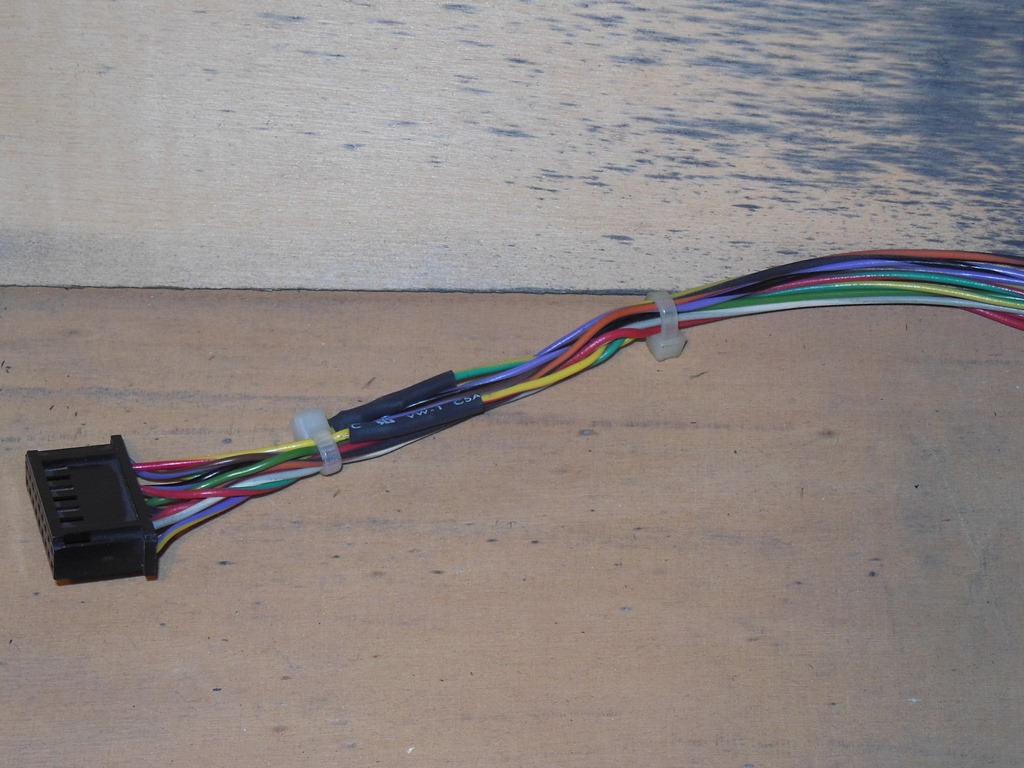
The right speaker is not used. The wires for it had blue sheathing suggesting it was not wired to the original connector. This would be consistent with the later universal uprights that were wired for stereo but the extra speaker cables are tied up unused (since the usual Konami connector has no pins for it).
|
Whilst the soldering equipment was in the back of the cabinet I took the opportunity to remove the 2-pin connector hacked into the control panel wiring and repair the cut.
|
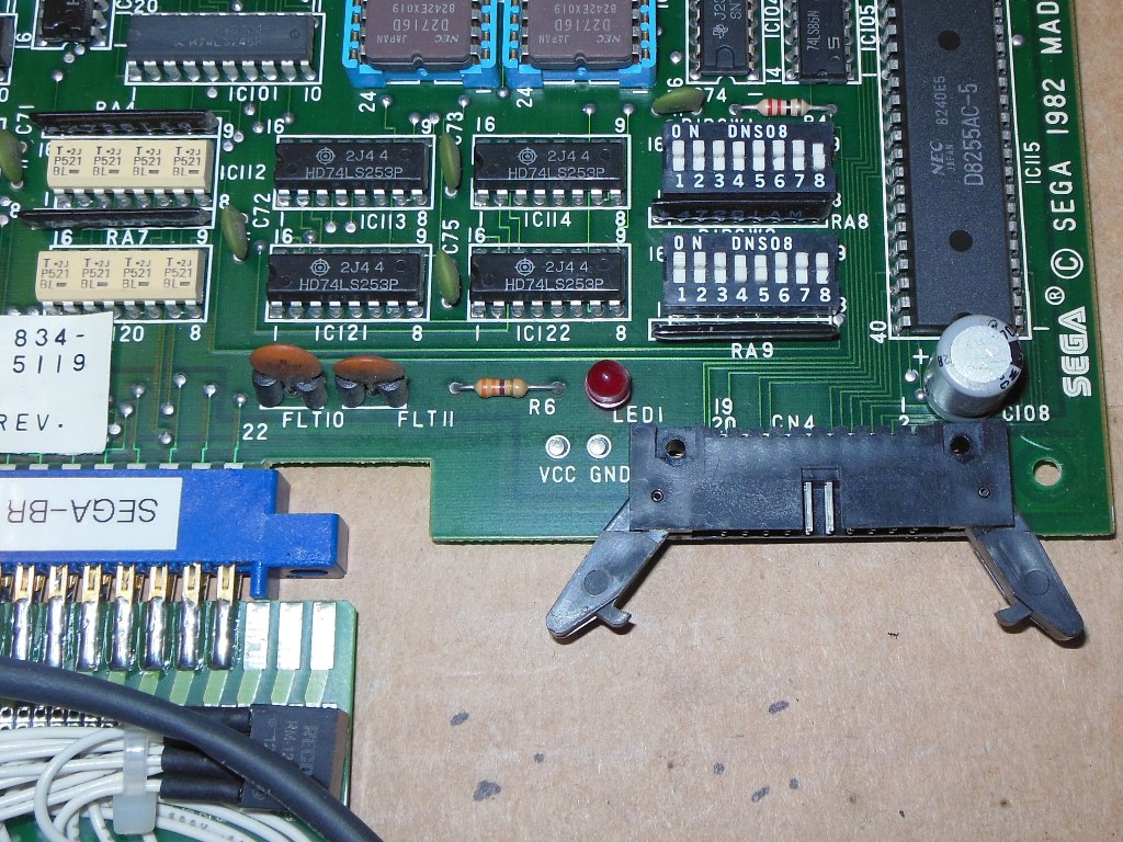
Before trying the game PCB in the cabinet I set the DIP switches to reflect the Zaccaria cockpit cabinet configuration:
|
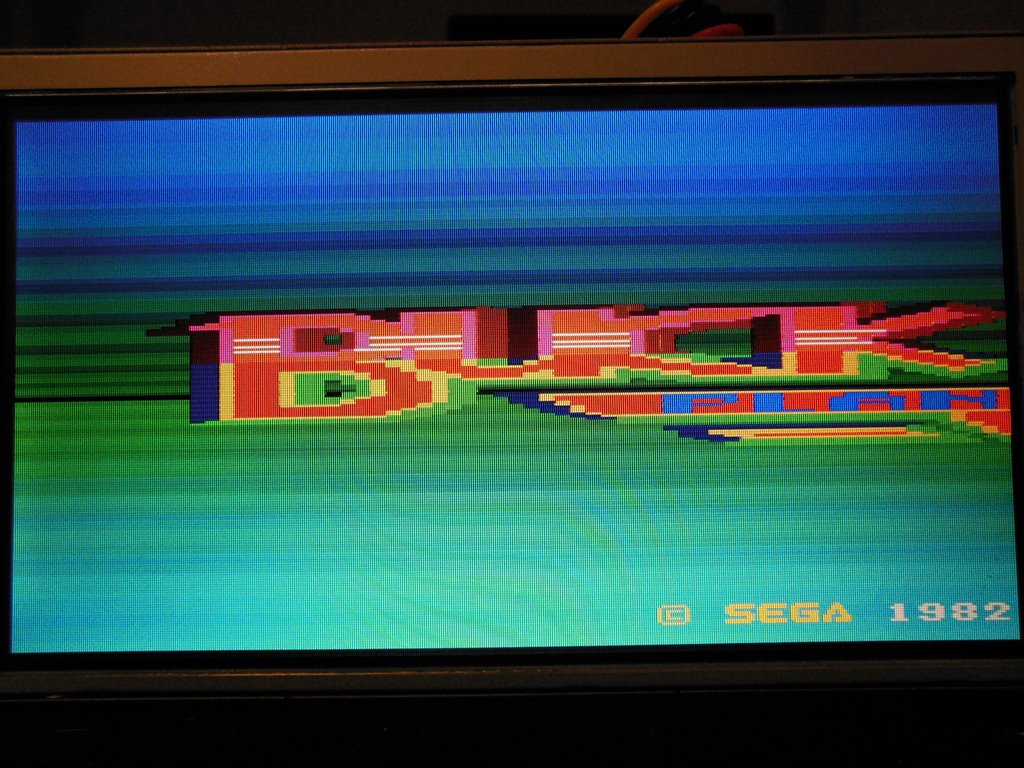
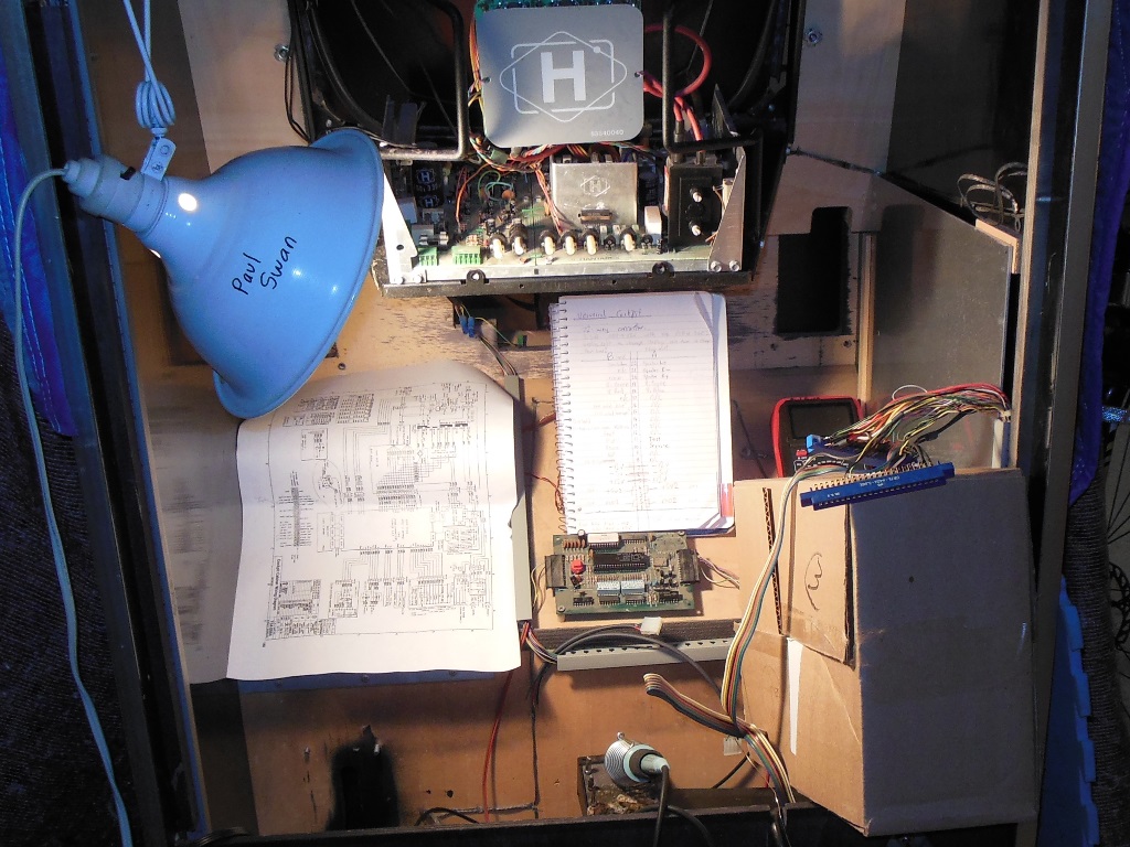
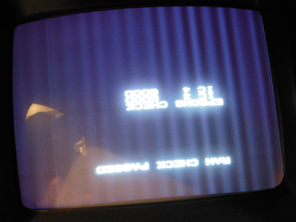
First power on with the game PCB fitted temporarily without the sound board came up fine on the monitor. Checking over a few basics revealed the following:
|
The replacement uPC624 DAC arrived and replacing the dead one in the board fixed the graphics. The game seemed to play fine with no further issues.
|
A friend on the Dragons Lair Fans forum was close enough to the wrecked "Vossen" arcade to be able to rescue parts from the Buck Rogers cockpit. It would have been great if the back marque, monitor glass and instruction cards had survived but they were all missing :( The pedal and cash box door were rescued and looked in good condition. They were packed up and shipped over to me :)
Note that the service panel has only a single volume control whereas mine has two and is wired for stereo.
|
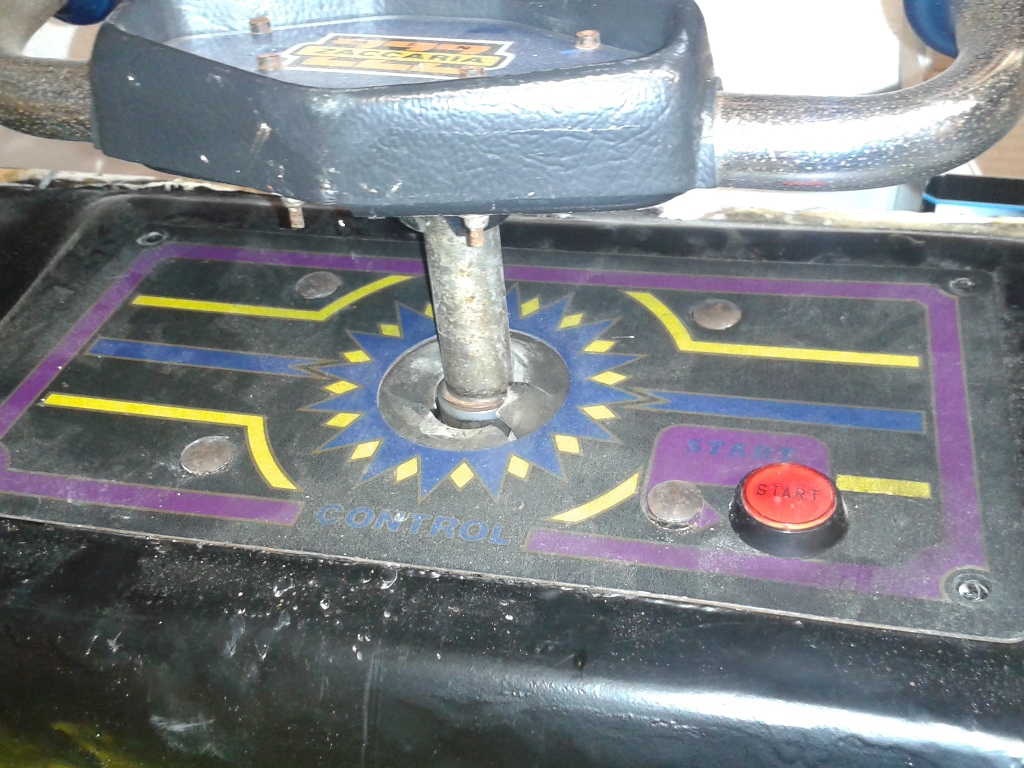
The pictures of the control panel confirmed the forums suspicion that the "Vossen" Buck Rogers was the one vernimark had previously restored using a fiberglass molded repro control panel. No other examples of the dedicated Zaccaria Buck Rogers cockpit had been known to have survived :(
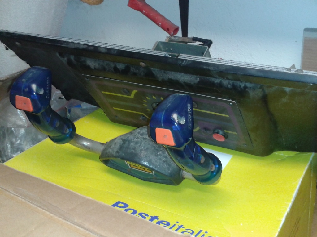
Note that the controller handle grips are different to the ones on my mine (mine look like they are the same as the Zaccaria Tron handle grips). Also note that the start button is labeled with "START" whereas mine is a blank button. I suspect my Universal machine is a later model than the original Buck Rogers model.

|
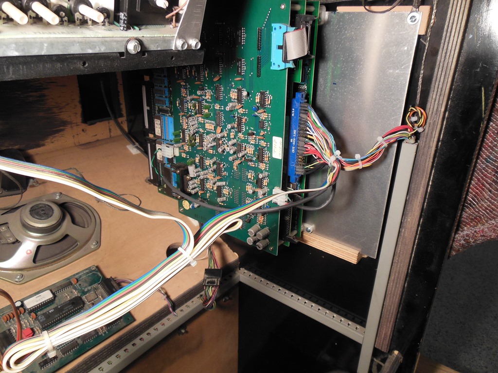
The game PCB needed a small amount of creative footwork to get it mounted on the plate in such a way as to not foul the plate guide in the cabinet. Once completed it fitted fine in the cabinet.
|
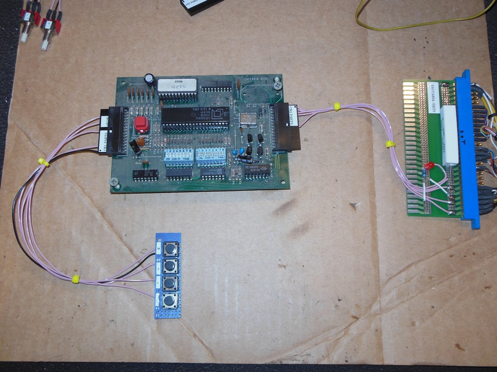
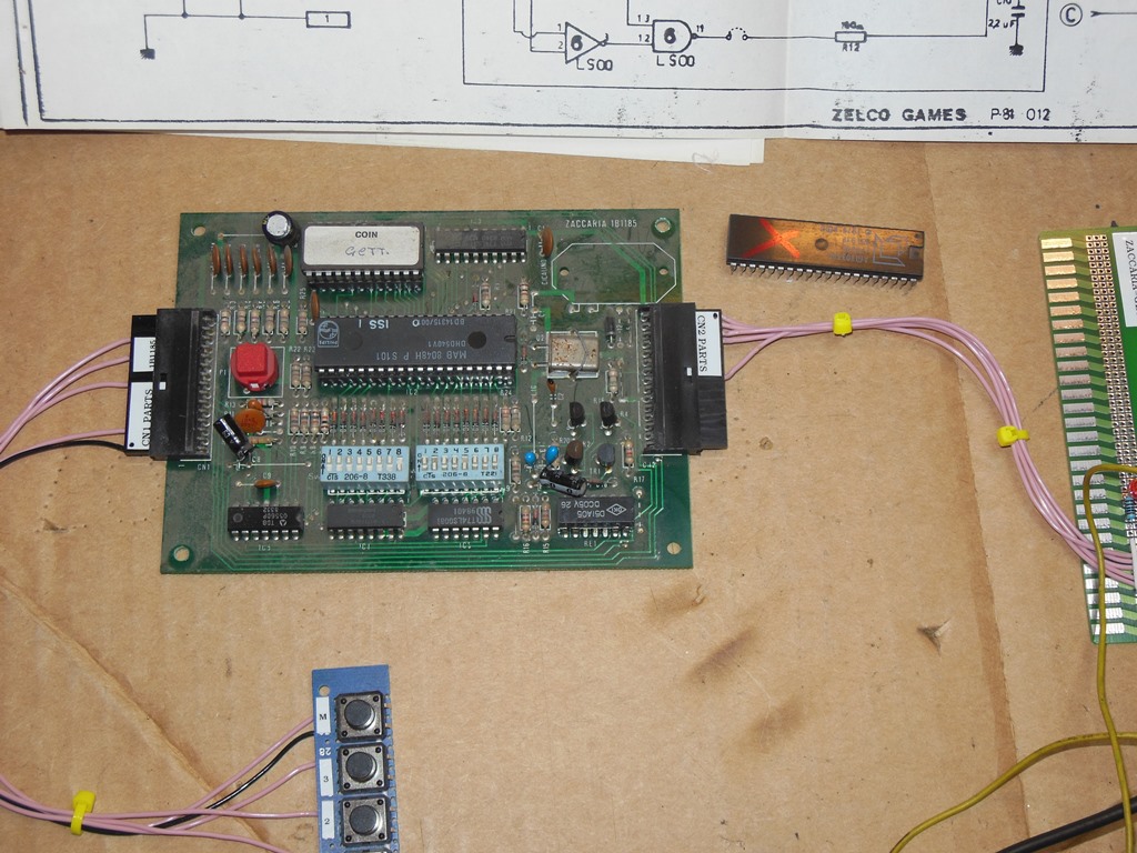
On the bench the credit board behaved the same as it did in the cabinet - coin inputs yielded no output. Poking around with a scope didn't turn up anything obvious - the clock was running, CPU address and data were all running and looked OK, coin inputs were getting to the CPU but there was no output at the CPU. Trying a different CPU fixed the board.
The board uses an 8035 microcontroller in a ROM-less configuration as listed
in the following table from the datasheet for this series of device:
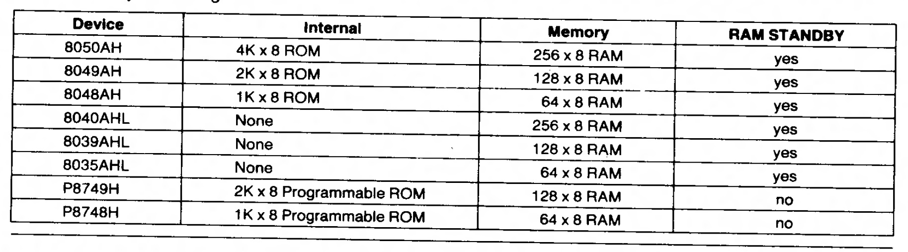
There are a lot of internal ROM versions of this CPU used in various embedded control
applications under the moniker 8048 that can be used to replace 8035 because the
internal vs. external ROM is selected using an external pin on the device. The most
widespread use I know of is in PC keyboards in the 80's & 90's.
In this case I had a Philips MAB8048 tagged "ISS 1" from who knows what that worked fine in
the GETT. The other members of the family with more RAM would likely also work so
there is a lot of choice for replacement parts.


|
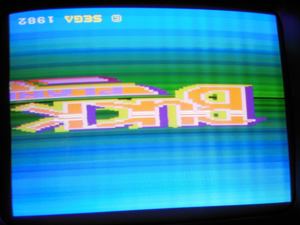
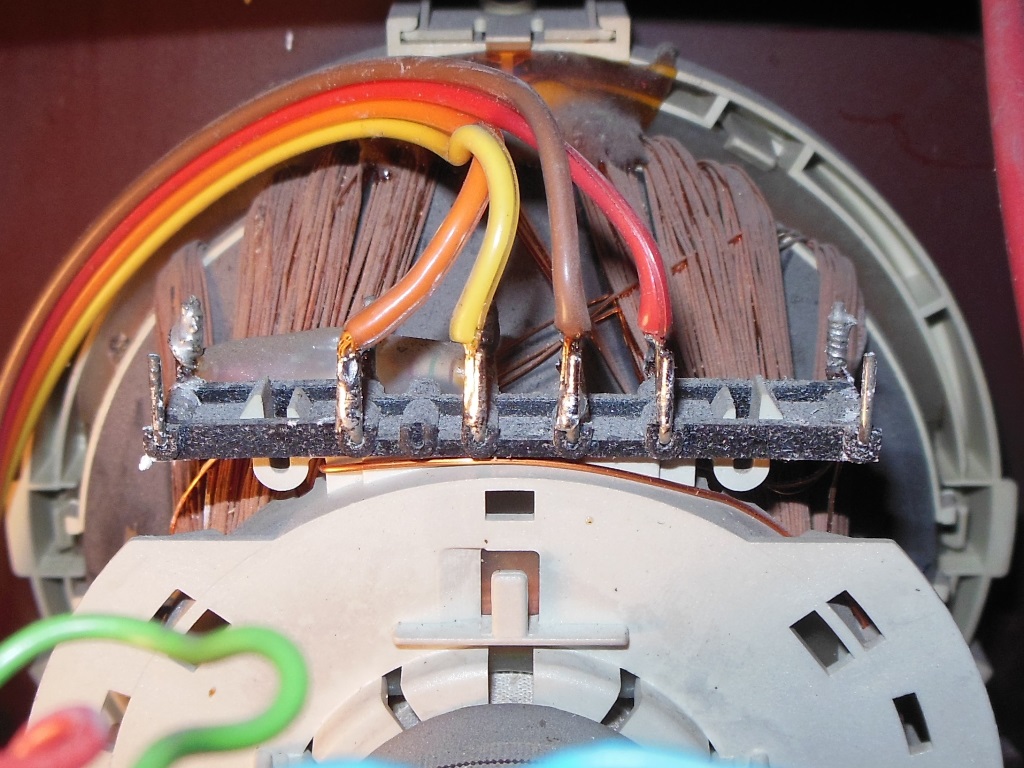
This was the first monitor I'd come across that has had the picture upside down. Not only that but this particular game doesn't have a DIP switch option to flip the picture to correct it. Therefore, a yoke connection swap was needed to fix the picture orientation. Since flipping the vertical yoke connection would mirror the image horizontally, a horizontal flip is also required to compensate.
The 900E manual shows the chassis-to-yoke wiring as straight through but the yoke connector on this monitor had both vertical & horizontal crossed. I checked with my test CRT and that also had a cross on the connector like this. Since these connectors are hard to come by and I didn't want to risk damaging the connector by trying to remove the pins and reinsert them I decided to swap vertical & horizontal on the yoke (that'd also been done on my test CRT).
|
The cross was straight forward since vertical & horizontal are paired on the yoke.
|
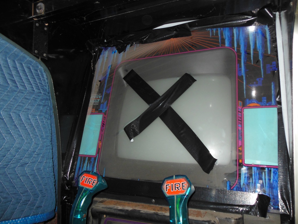
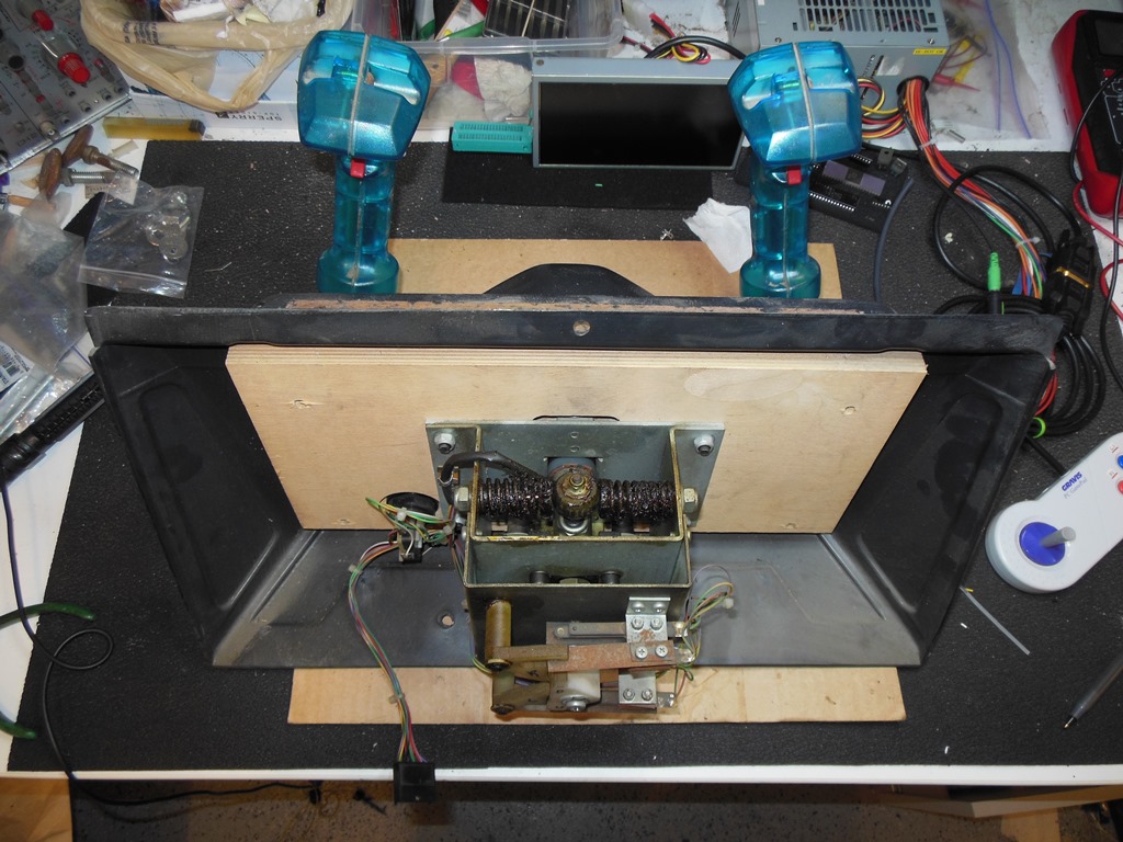
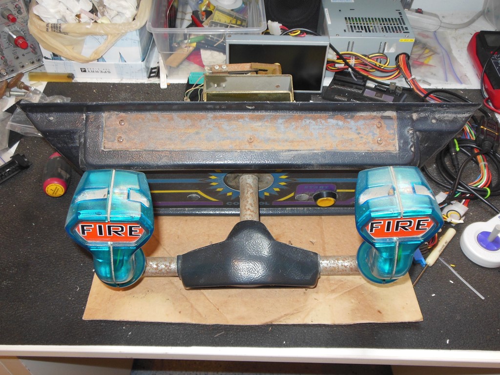
The yoke control panel was generally in good condition and needed only a wipe down with a damp cloth and the leafs cleaning (by closing the leaf on a thin piece of card and running the card through to clean off the contact surface - leaf switches should never be cleaned with sandpaper! The two main issues were that the yoke handle needed re-chroming and the blank top plate (that protects against cigarette burns) was rusted. The latter could be restored easily with sand and re-spray however it was bolted behind the yoke mount such that to remove it would require the whole panel & yoke completely disassembling :(. For now I decided to cover with a piece of black duct tape.


|
After final cleaning of the monitor, surround & glass I reassembled the monitor front and added in the control panel for another power on test.
|
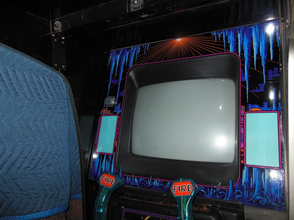
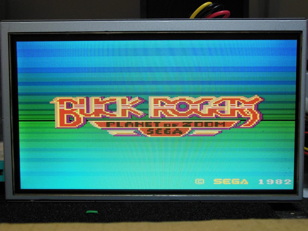
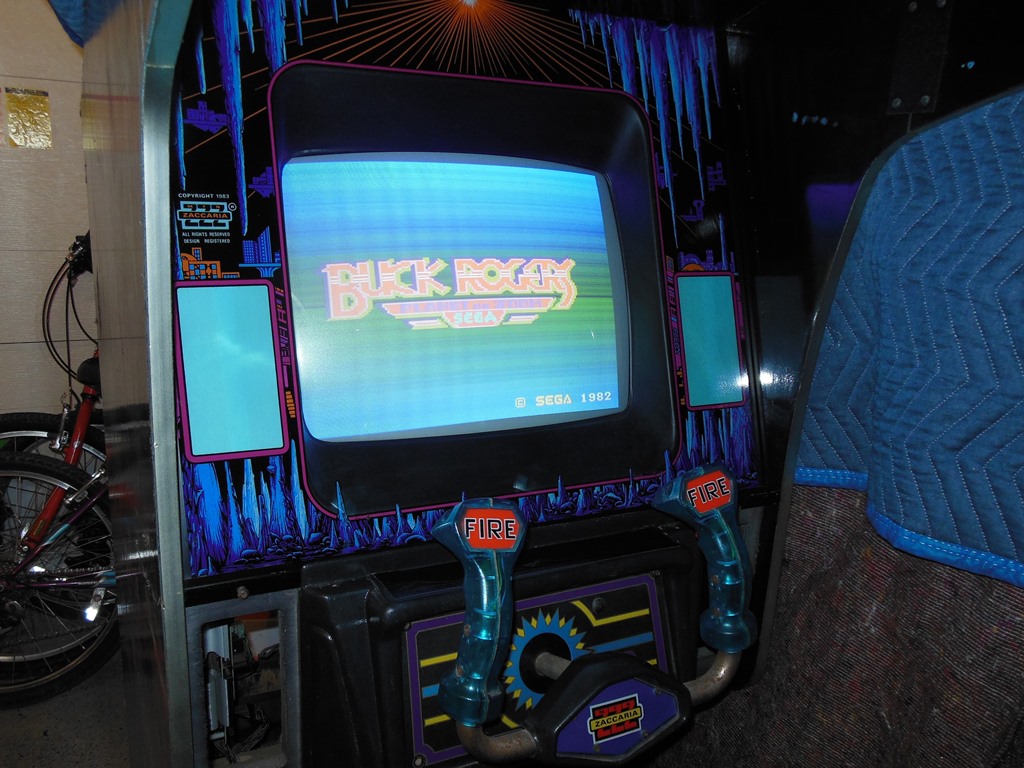
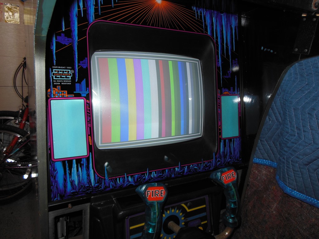
Power on - the picture was the right way around and the graphics all looked good, the coin inputs were working and the sound connected up with everything present. It was fully playable! There was quite a lot of background hiss on the sound (as there was on the bench also) that may need to be looked at. The monitor geometry wasn't too far off, needing only a small tweak of the brightness and sizes.

|
The picture looks pretty good. The only complication of note was that the horizontal size trimmer chipped during adjustment but as it was at the time was good enough.
|
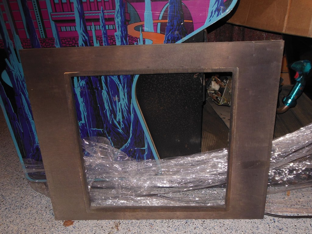
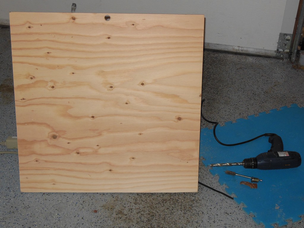
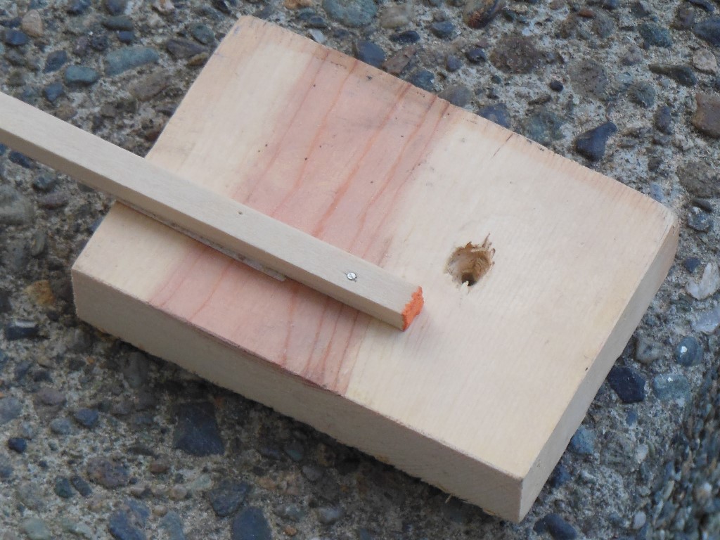
I selected the right thickness of a panel of plywood at Lowes and asked that they cut It to the correct size. They were long by about 1/8" on each side necessitating a labor intensive sanding exercise to get the panel to the correct size and compensate for skew. The key hole was straight forward to make with a normal drill. On this cabinet, the top and bottom of the back door has lips that match the top and bottom panels. I didn't have any capability to cut such lips on a flat panel so I'd had the panel cut slightly short and then bought half-width trim strips to tack & glue on the ends instead. I bought the thinnest tacks I could find but still needed to verify that the trim strips wouldn't split when they were used. Success! The tacks worked fine.
|
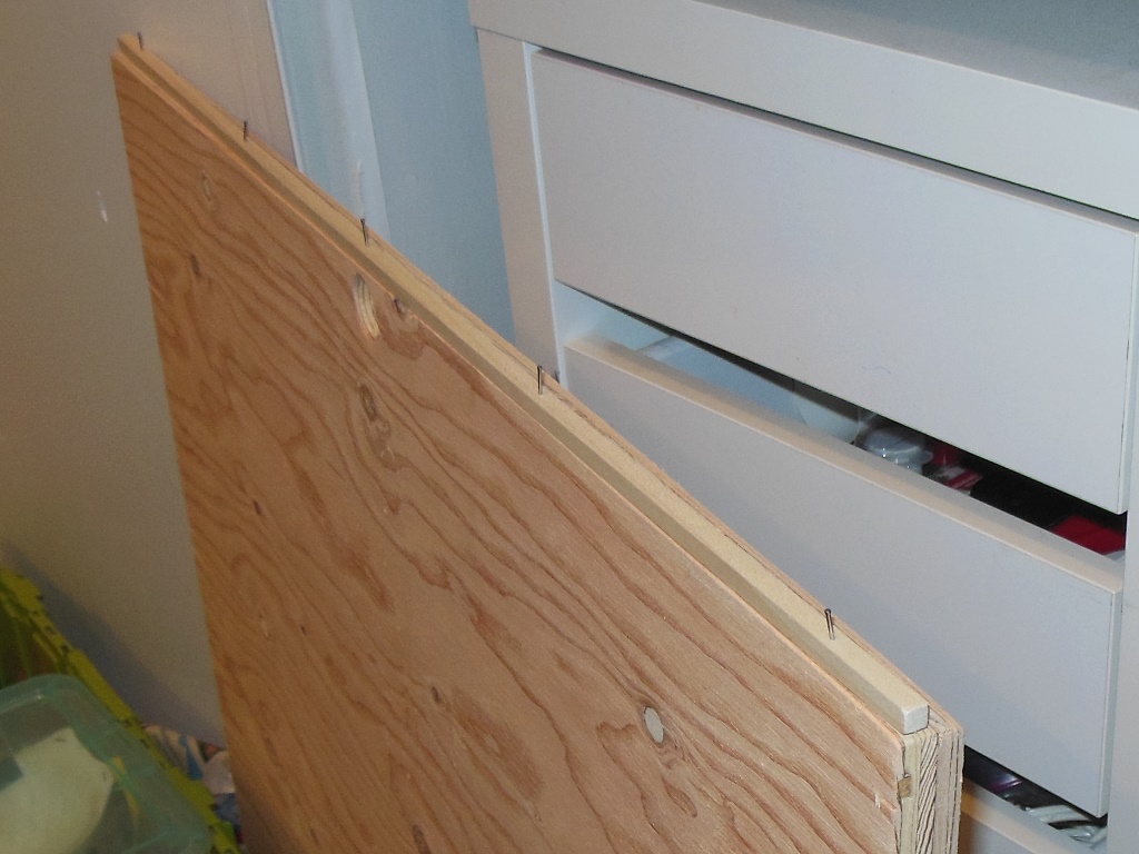
I pre-tapped in the tacks onto the strips, glued the strips and then tacked them in place on the panel leaving it to set for a few days with additional weight on top.

|
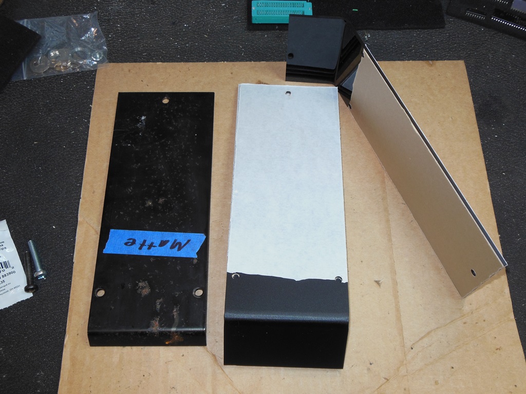
There was one metal side blanking plate remaining so I needed to make at least one more to cover the right hand opening. In order to have them match I decided to repro both sides in matt plastic. Tap Plastics had matching plastic sheet (matt on one side) and were able to copy the blanking plate including the bent lip and screw holes. The minimum bend Tap can do is 4" so the under lip is longer than on the original metal plate but in this case it doesn't matter as there is enough room for the under lip to be longer.
I was also short of the screws to mount the right blanking plate. Lowes had the right screws but not in black anodized colour. A Sharpie of the screw heads seemed good enough to blacken them (the sales guy at Lowes also suggested nail polish as means to colour the screw heads).

|
I discovered that the usual metal credit button bracket I'd been using on all my other cabinets doesn't fit on the coin door used in the cockpit - the door frame has a lip on the inside that this fouls the bracket on the door. I decided instead to use the left blanking plate to hold the credit button.

|
The button wires were run neatly along the inside and through the round hold to join the rest of the coin door loom on its way to the door to be connected up to the coin switch.
|
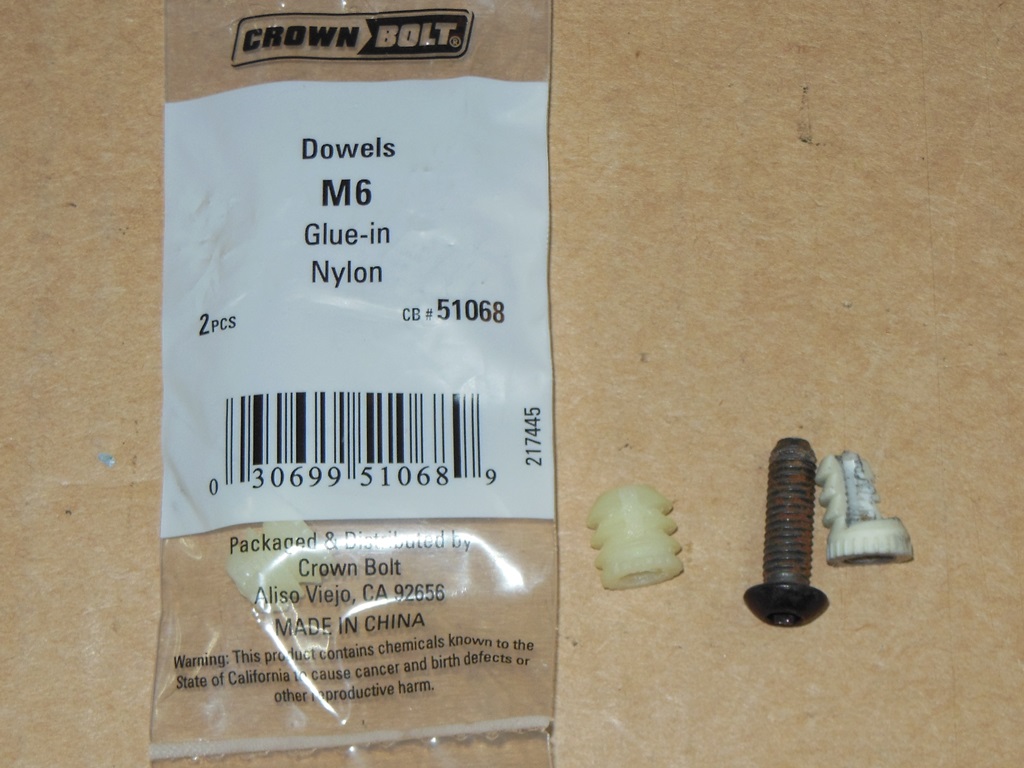
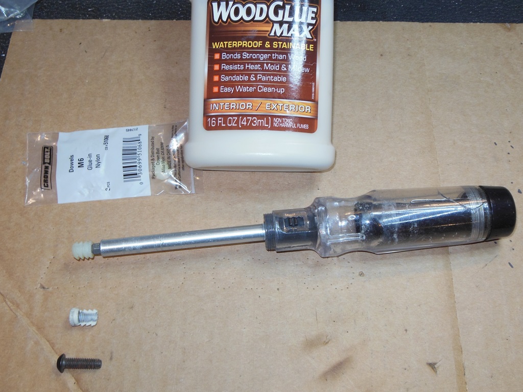
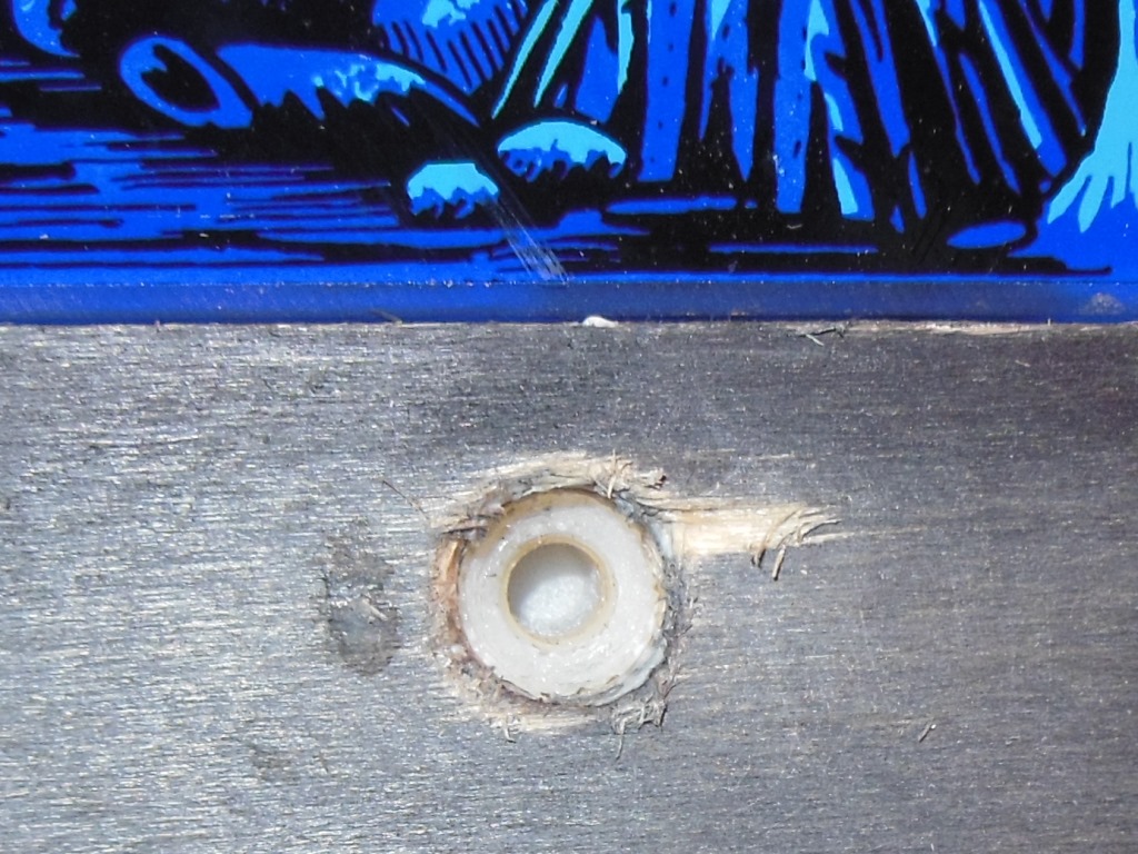
The center screw socket for the bracket that holds in the monitor glass was broken. The original socket was split design that the screw splayed to bind into the wood when screwed. Lowes had something similar in the right thread but closed with no splay. The replacement needed to be glued and then tapped into the frame at the right depth. The end result was perfect.


|
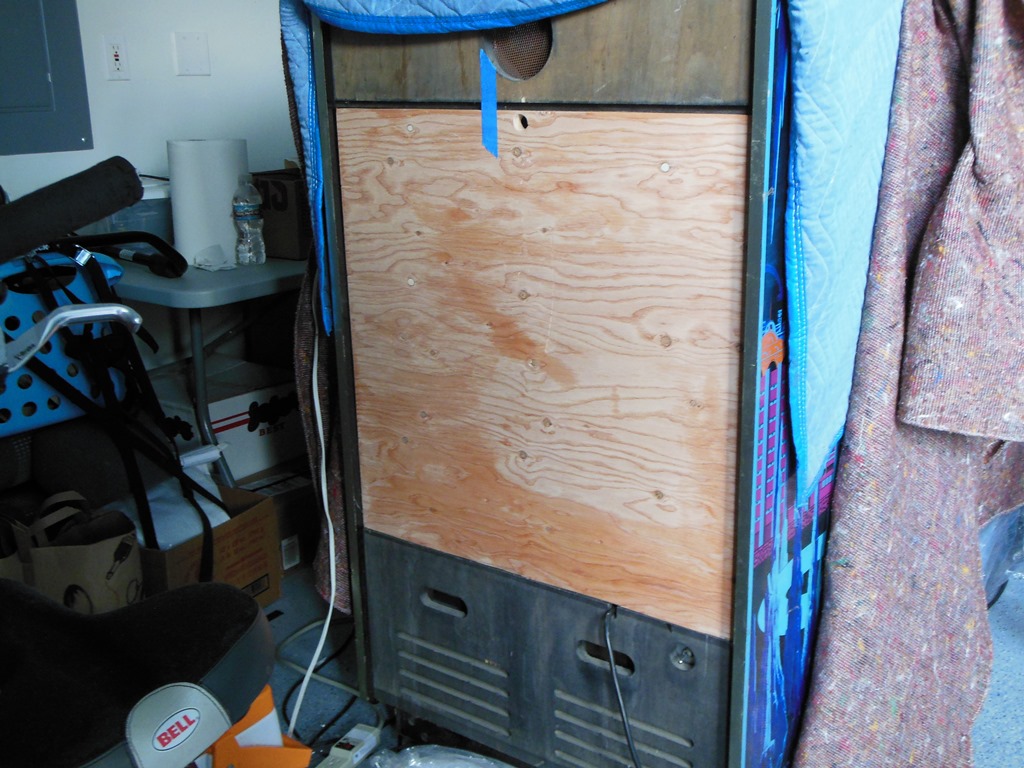
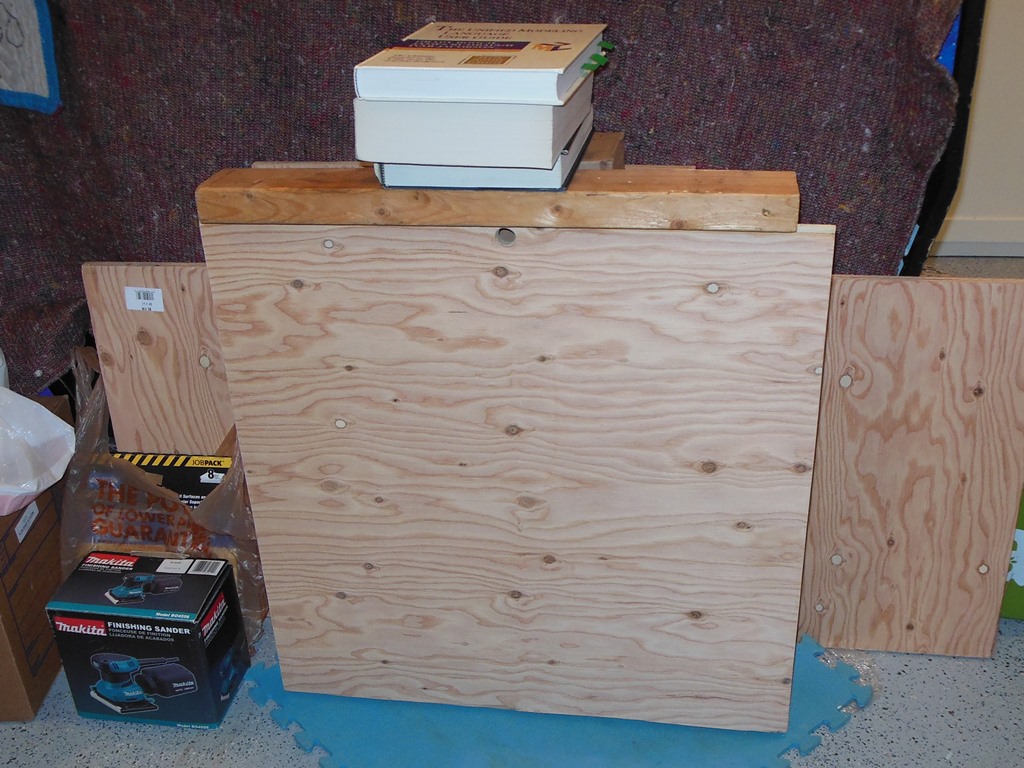
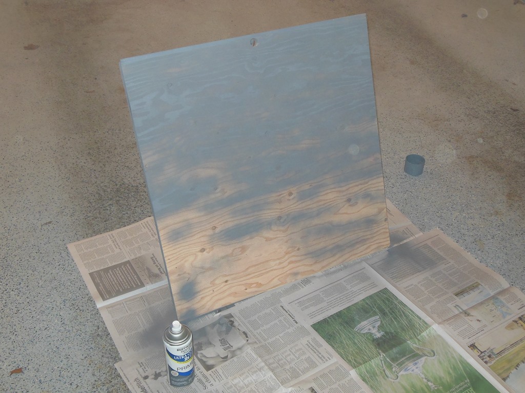
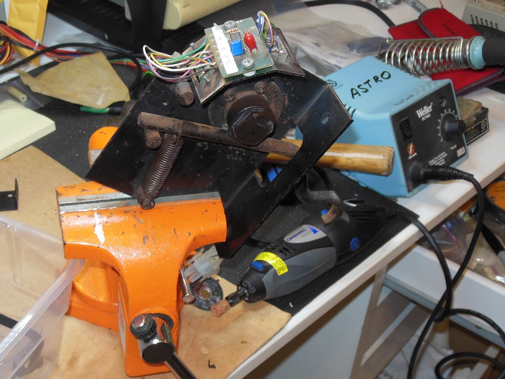
With the door all set and the weather being good it was time to paint the repro back door. The lip on the cabinet was quite thick that needed an angled clasp making to fit (made simply from a flat clasp held in the vice an hammered to give two bends).

|
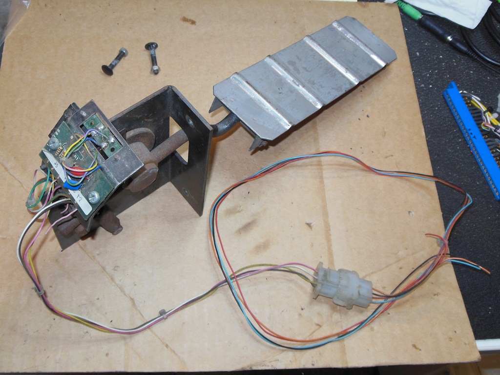
Finally the cash box door and pedal assembly arrived from Europe. The cash box door fitted perfectly though slightly mismatched due to mismatched surface rust. The pedal assembly looked complete and would plug straight in. The bottom bracket was a little bent out of shape but repairable.

|
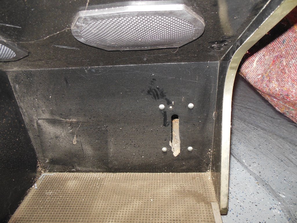
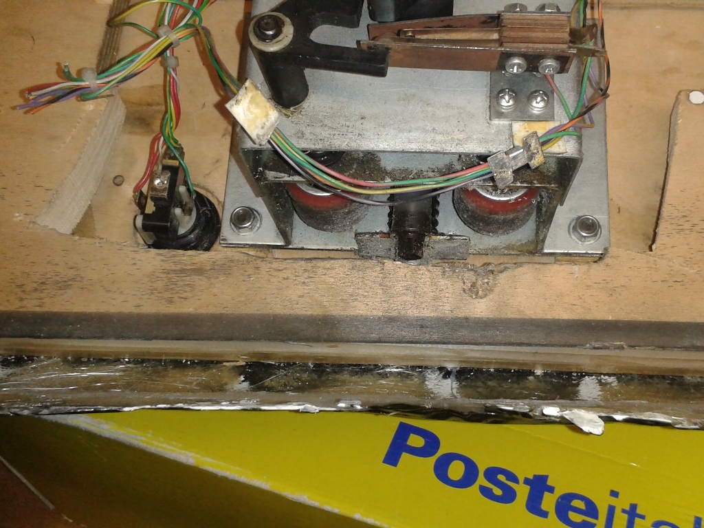
It's not clear if the Universal cockpit originally came with the pedal or not. In the metalwork included in the cabinet there was a blanking plate that looks like it was intended to cover the pedal hole and there was no sign of any existing screw holes in the floor of the cab indicating a pedal was ever fitted. That said, also in the metalwork was a slotted wheel for the pedal opto-coupler.
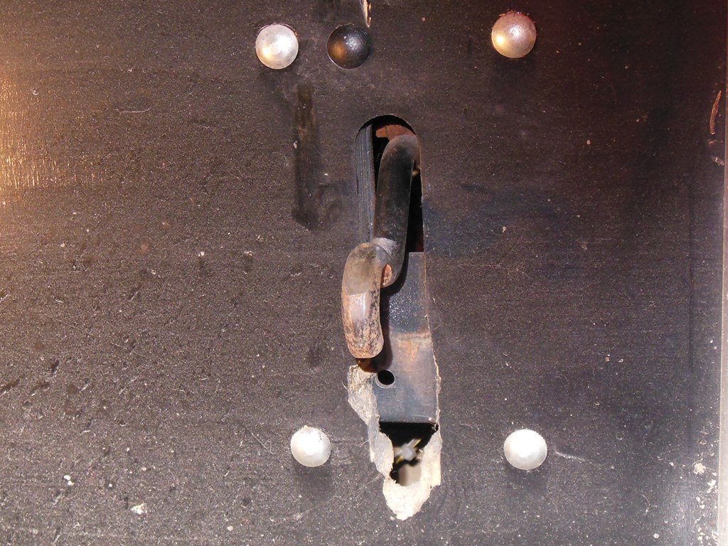
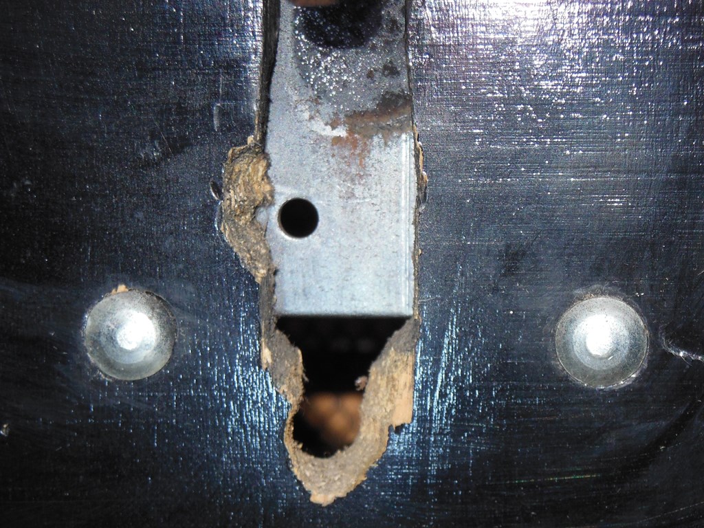
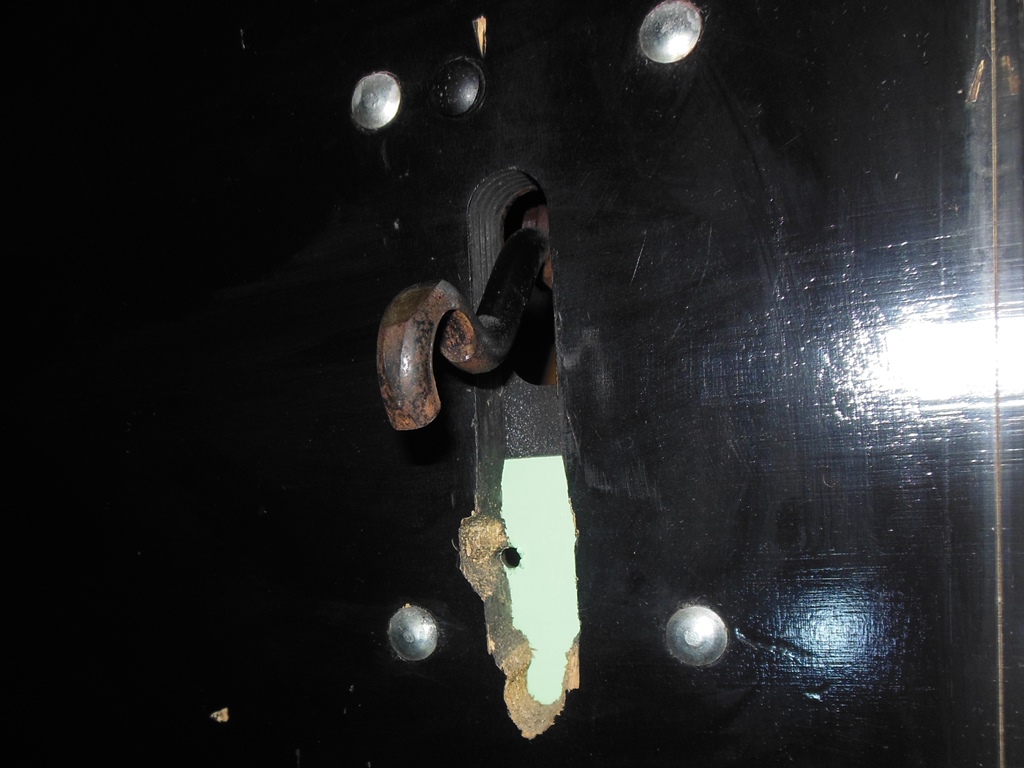
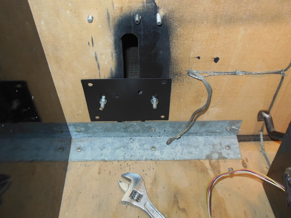
This particular cabinet had had the pedal cut out widened (likely to accommodate a driving game analogue pedal). Unfortunately this widening had removed the lower mounting hole for the original pedal and added four larger bolts around the cutout. In order to remount the original pedal needed some additional accommodation work.

|
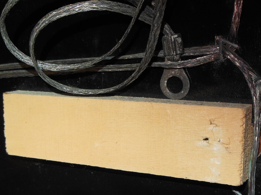
The pedal wiring still needed to be set. Power & ground were known but a little further
investigation was needed to figure out the signal wires (no manual for the cockpit had been
found). I got it wrong on the first attempt but there were only two wires and thus it was
right on the second attempt :)
| Pedal Pin | Pedal Wire | Cabinet Wire | Edge Pin | Signal |
|---|---|---|---|---|
| 4 | Grey | Orange | V | AccB |
| 6 | Black | Blue | W | AccA |
|
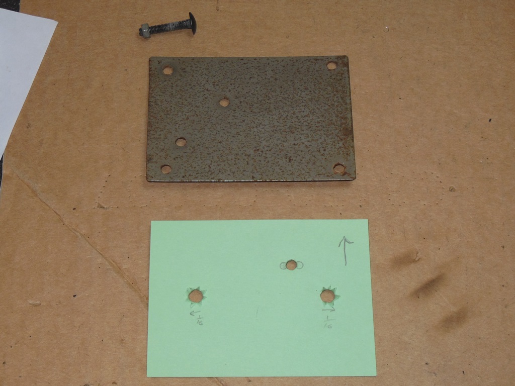
The plan of action for mounting the pedal was to use a metal plate to bridge the excess cutout and provide a new lower mounting hole. The plate was attached using the two extra bolts on either side (all four extra bolts were seized in the wood and thus left as is). I made a paper template first to get the holes in the right place and then used that to drill out a suitably sized piece of steel plate.
|
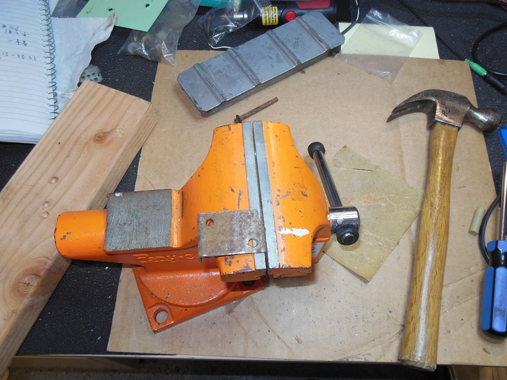
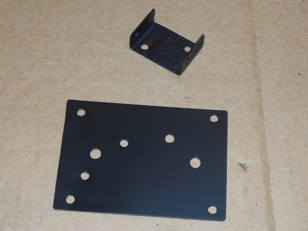
The pedal base bracket was rusty and bent out of shape, something that a little hammering in the vice easily corrected. I then spray painted both bracket and mounting plate to keep the rust at bay. The plate fitted perfectly.


|
The pedal assembly itself slightly fouled the lower right extra bolt that thus needed a small trim to remove the corner. With the pedal assembly fitted, the location of the base bracket could be determined and the foot plate fitted. After some adjustments of opto wheel to properly align it the pedal worked fine.
|
With all the wiring completed and working it was finally time to shrink the tubing and cable tie up the wiring to make it nice and tidy.

|
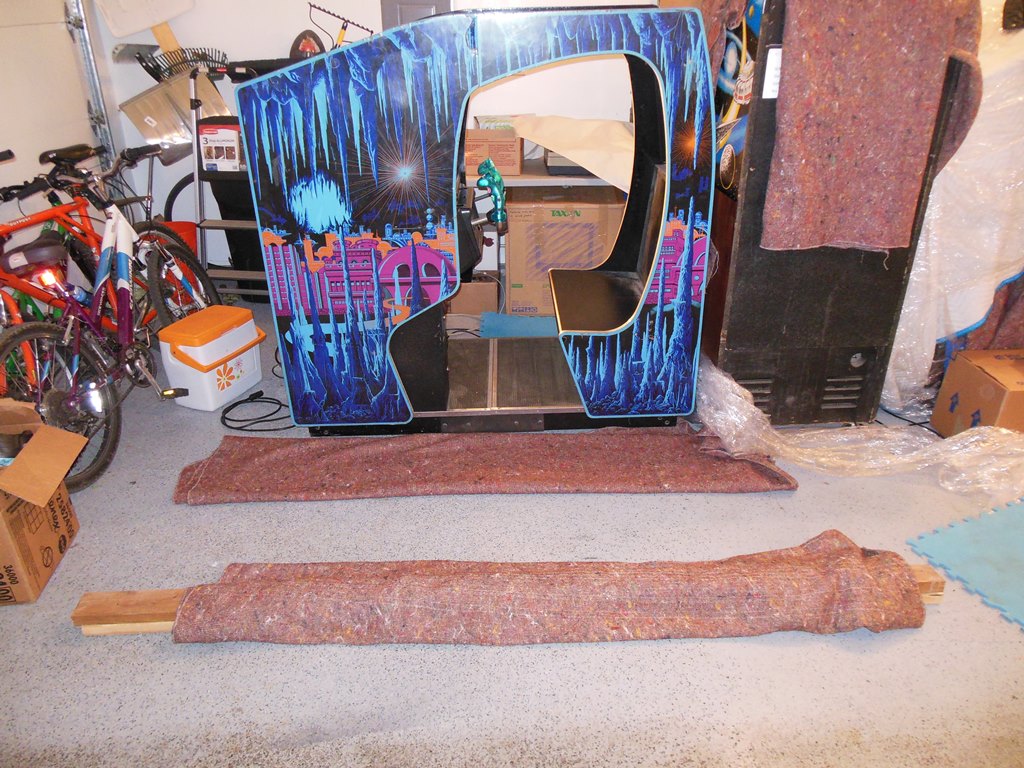
The original plan was to fit castors in the same way as I had on all my cabinets. To get access to the bottom a pair of blanket covered 2 x 4's were used to protect the side art so the whole cabinet could be flipped on its side.
|
This cabinet does not have the wooden angle mounts found on upright cabinets - instead there are eight metal corner brackets with feet screwed in. In this case, the center four feet were missing and the remaining four were set high and thus bent. Castors were not going to work with this cabinet and since I'd saved all the old feet reclaimed from other uprights I was able to use the best condition feet from that pile to put in all eight feet and adjust them to be quite low to mitigate the risk of transit damage. I also tightened up all of the foot mounting bracket bolts since most of them were loose.

|
With the machine completed and burned in OK it was time to wrap it up to go to the show.
|
The cabinet fitted in nicely as a row end stop and ran through the whole show without any major problems :)