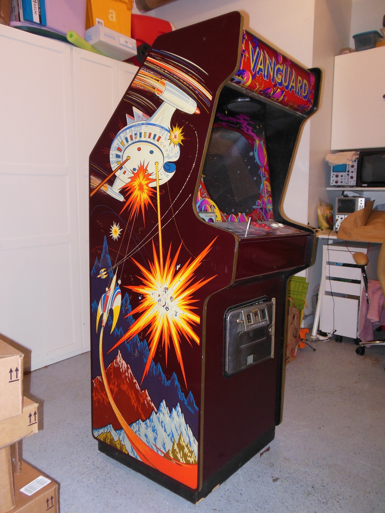


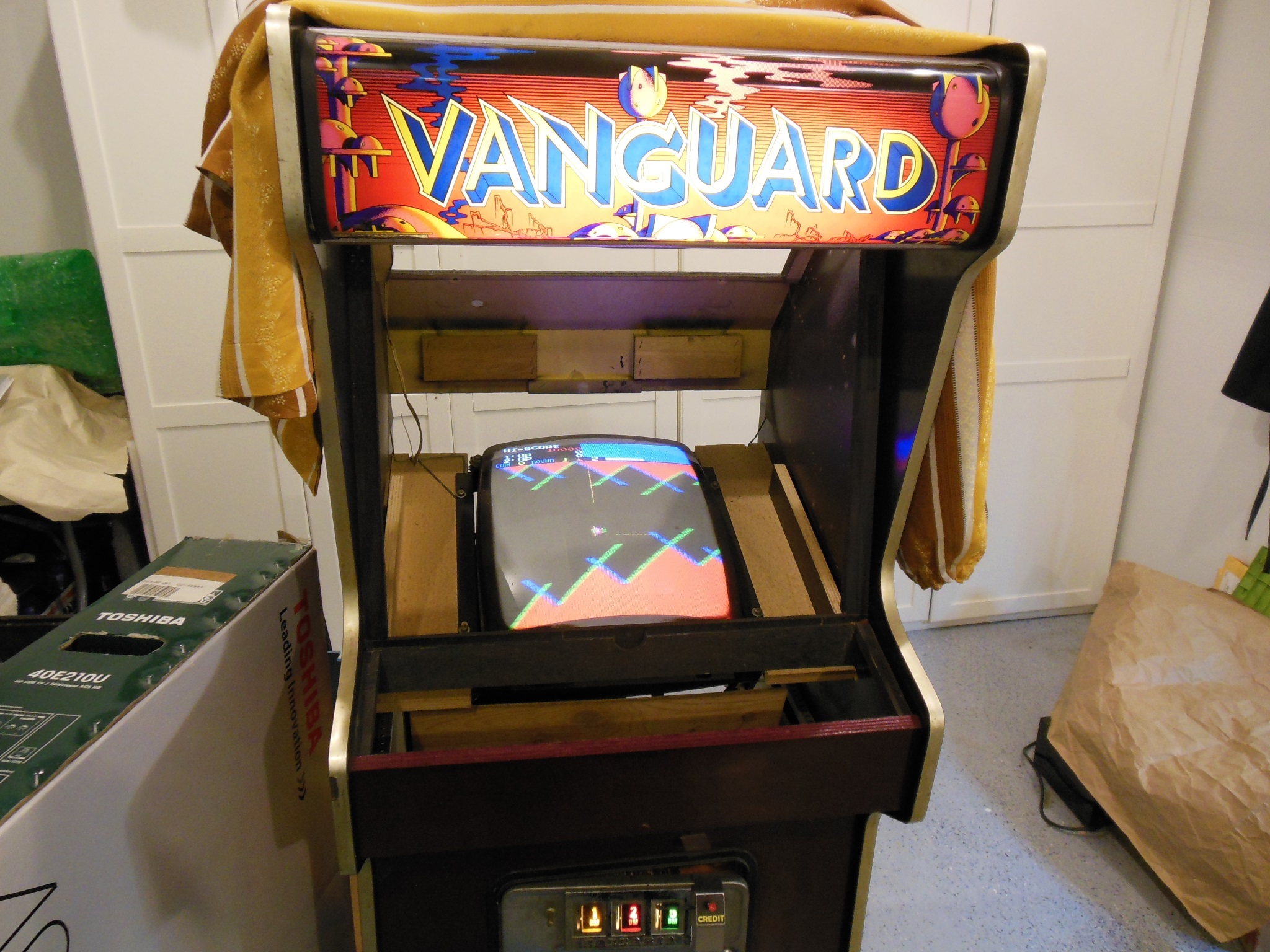
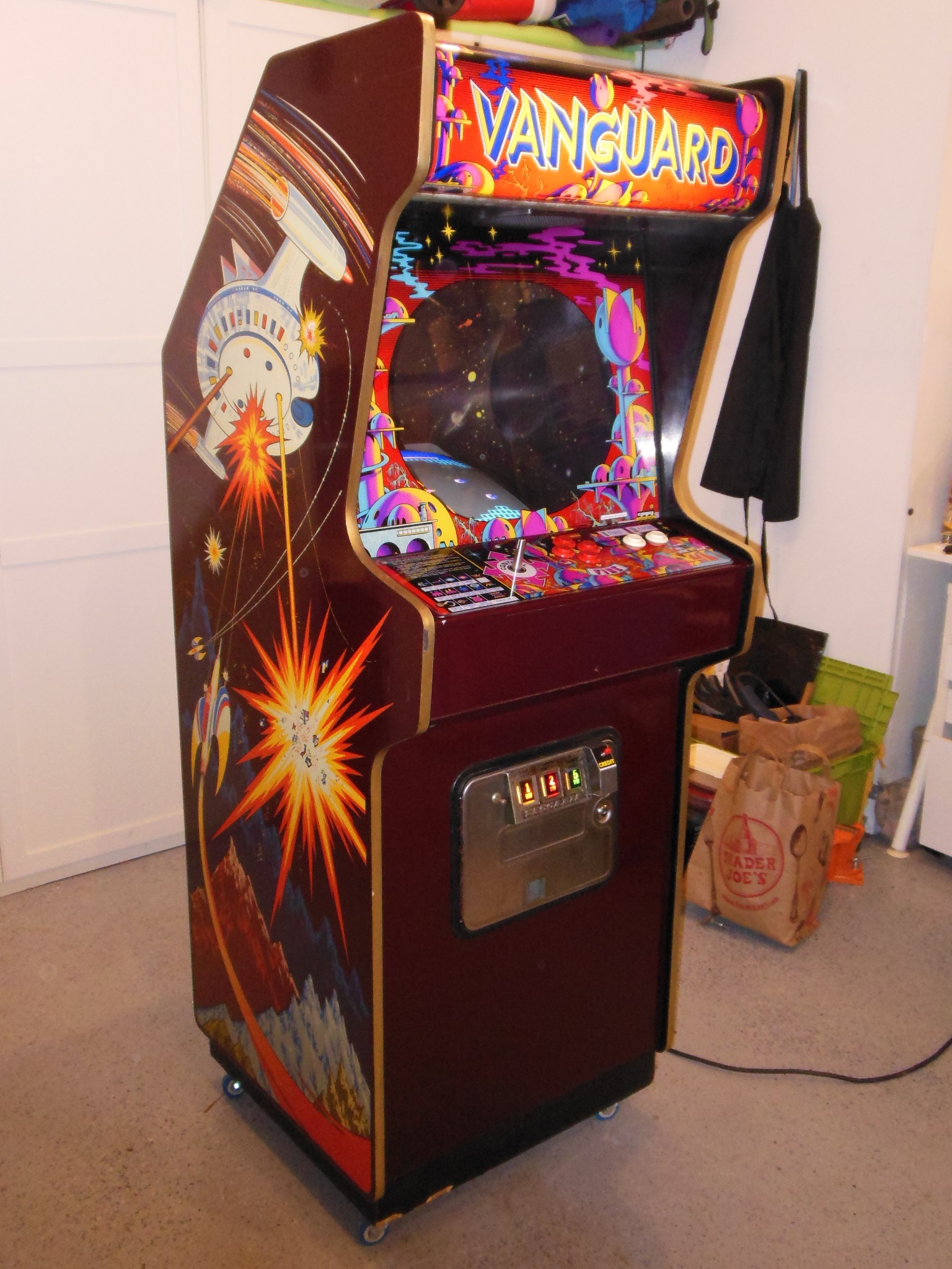
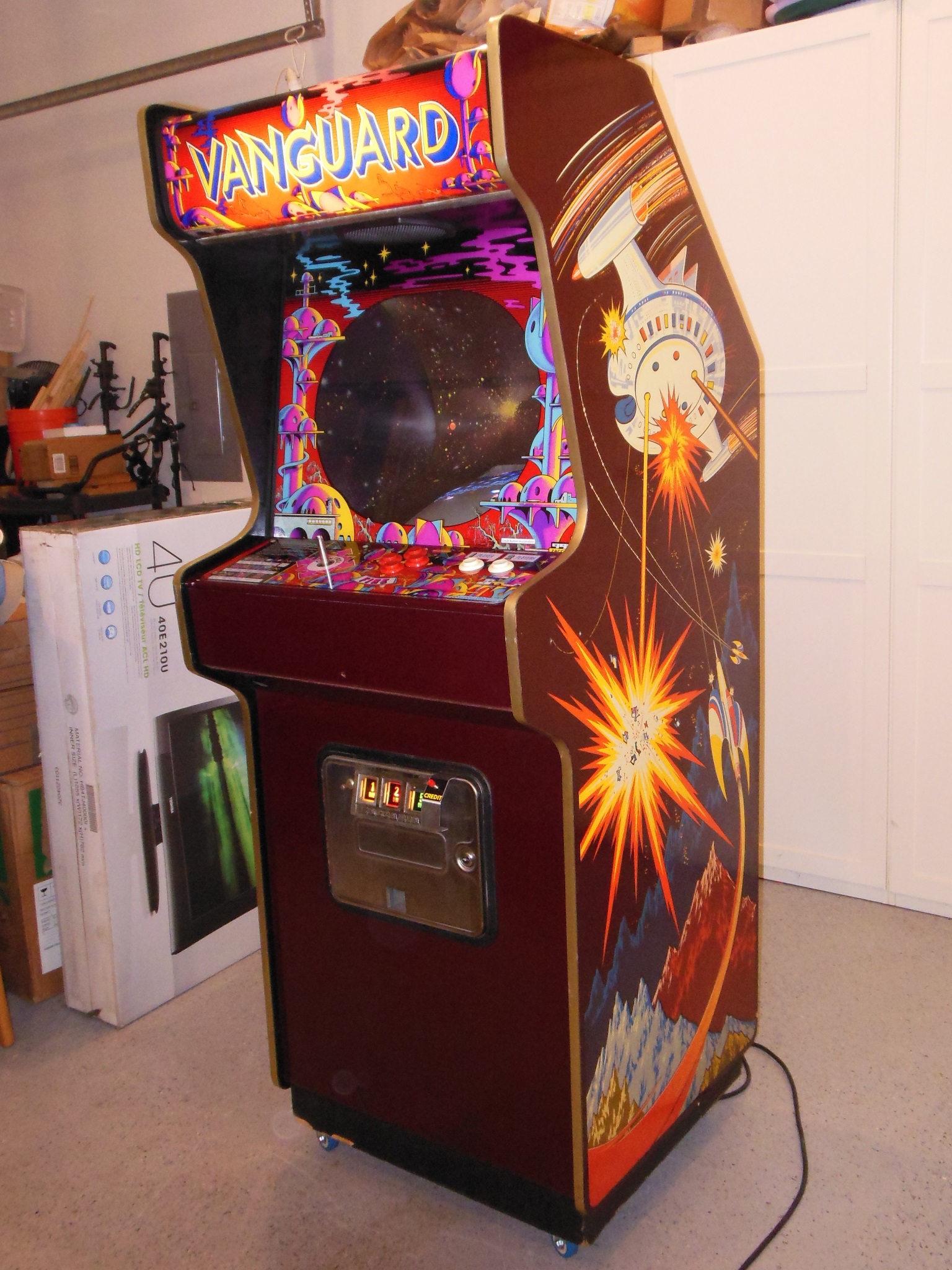
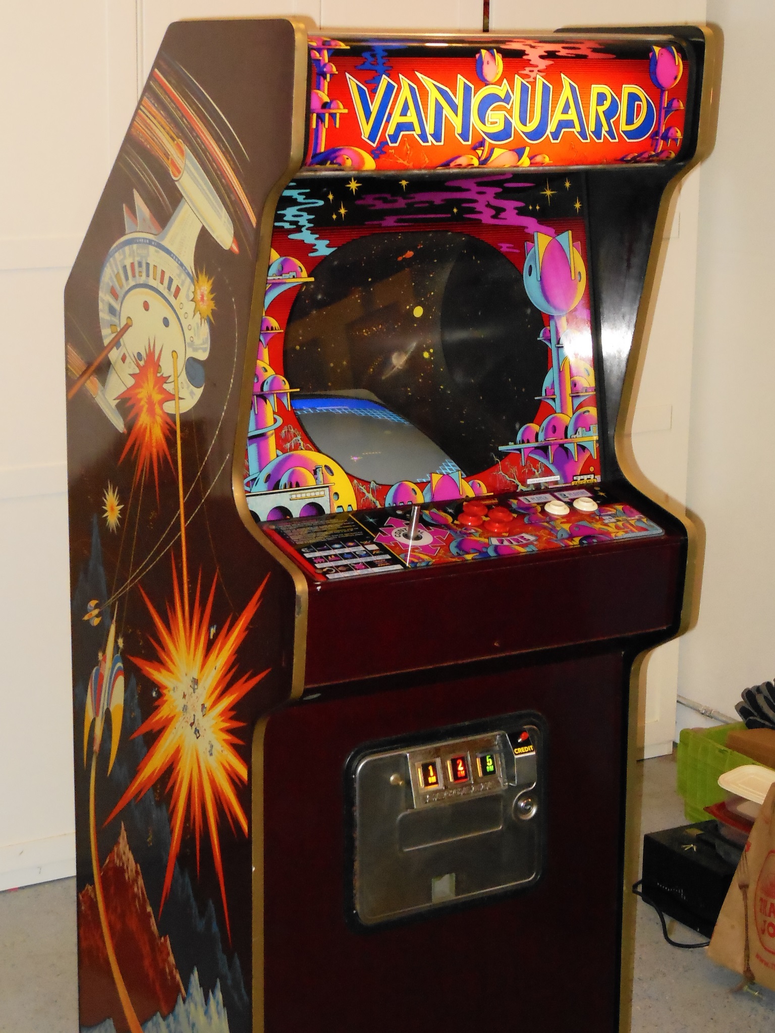
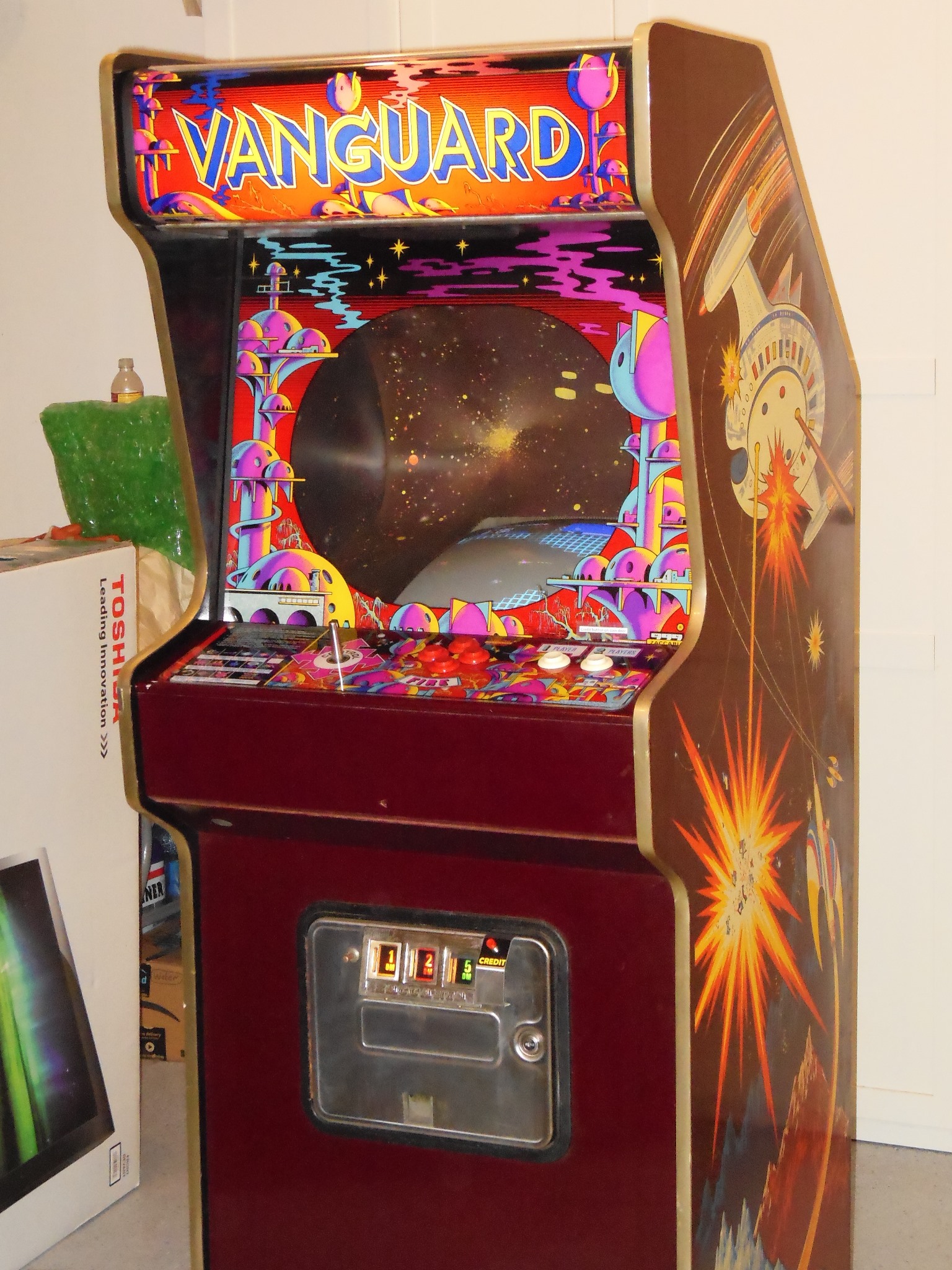
This Vanguard came from a German operators warehouse as a part of a bulk purchase deal arranged by a fellow UK collector.
|
|
Aside from a missing foot, the cabinet looked complete and in very good condition.
|
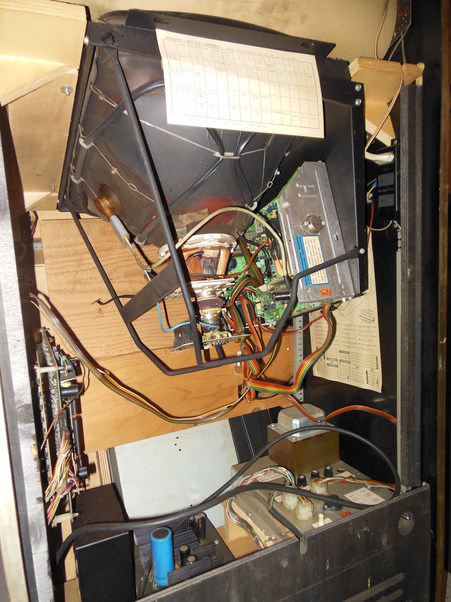
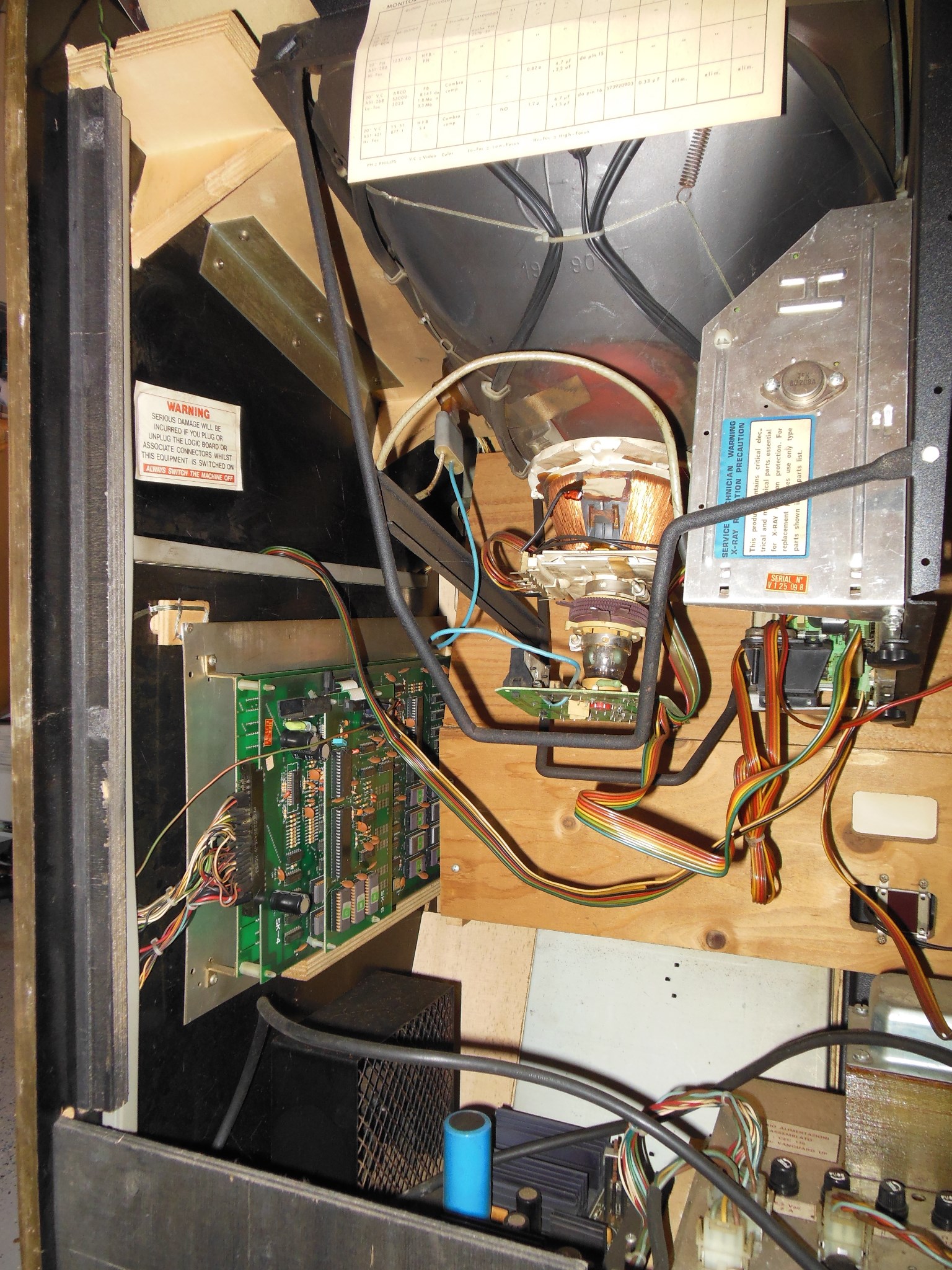
Consistent with the exterior, the interior was in pristine condition with all labels intact and all original. I did notice that that monitor DAG ground wire was loose, as was the monitor chassis itself.
|
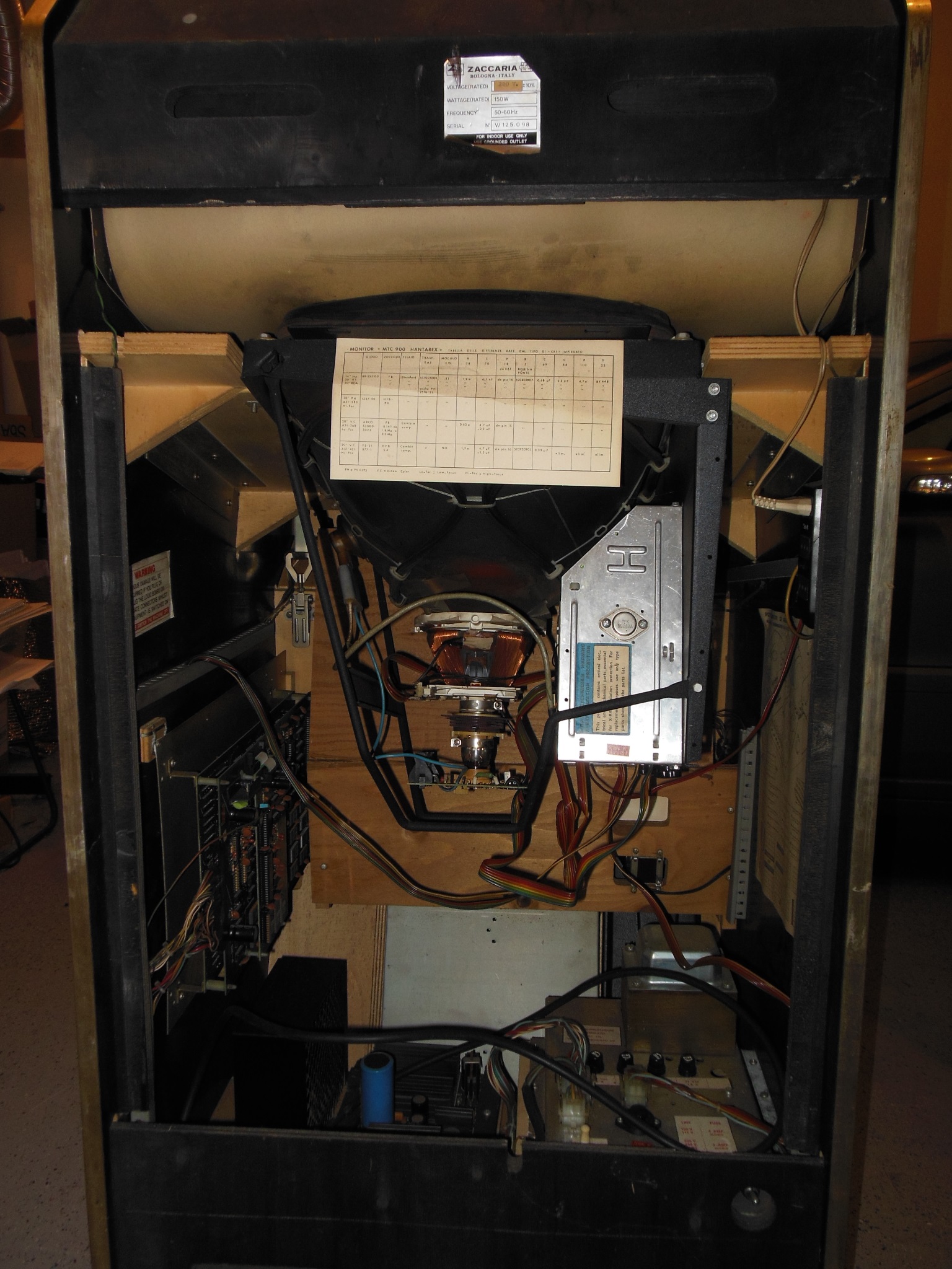
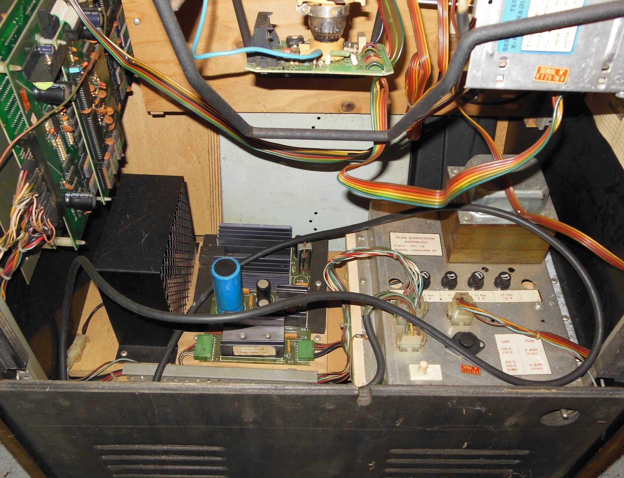
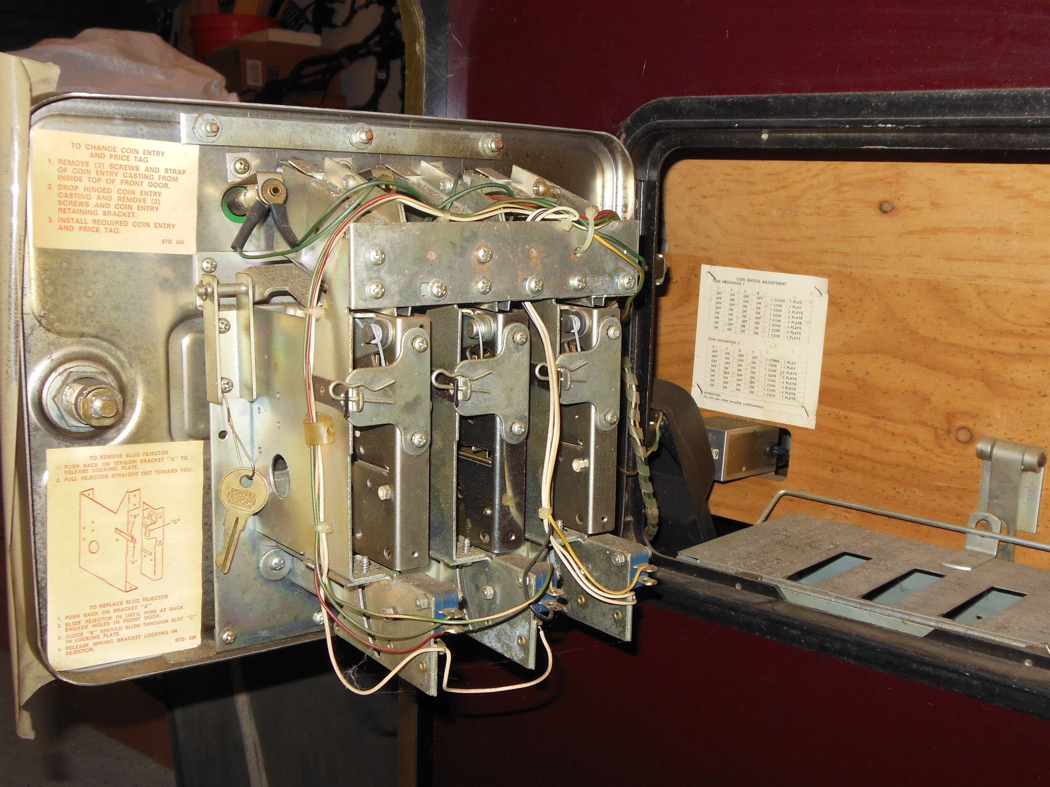
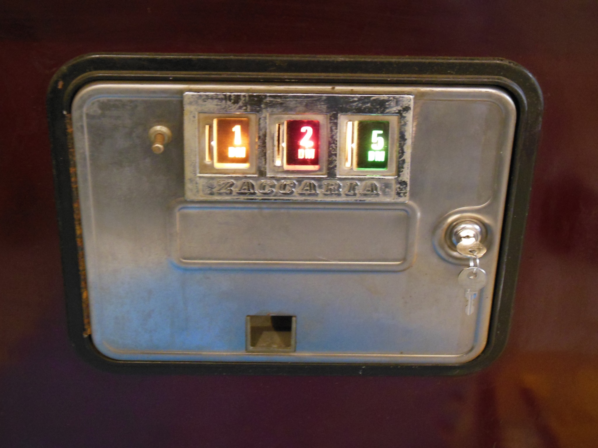
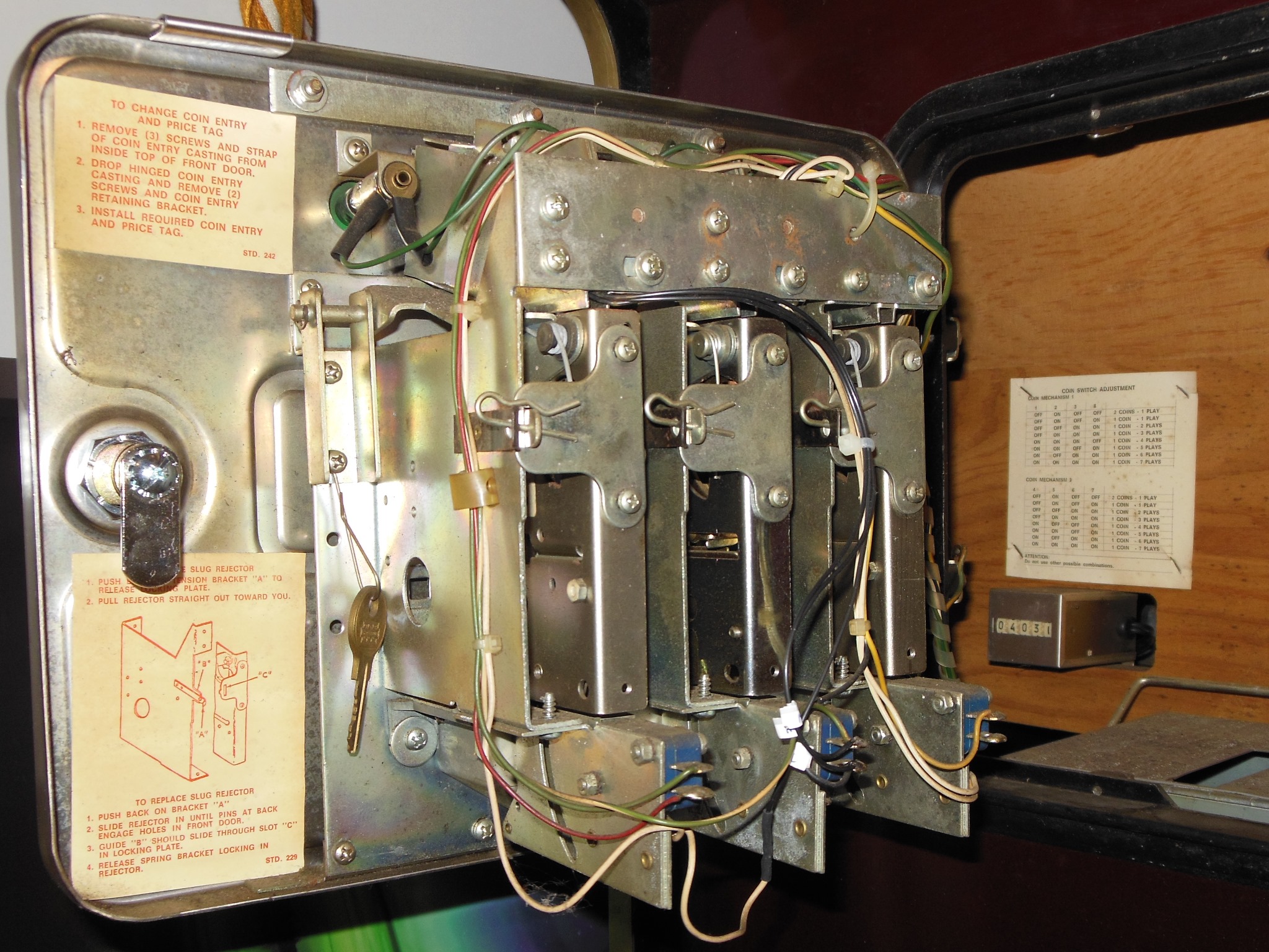
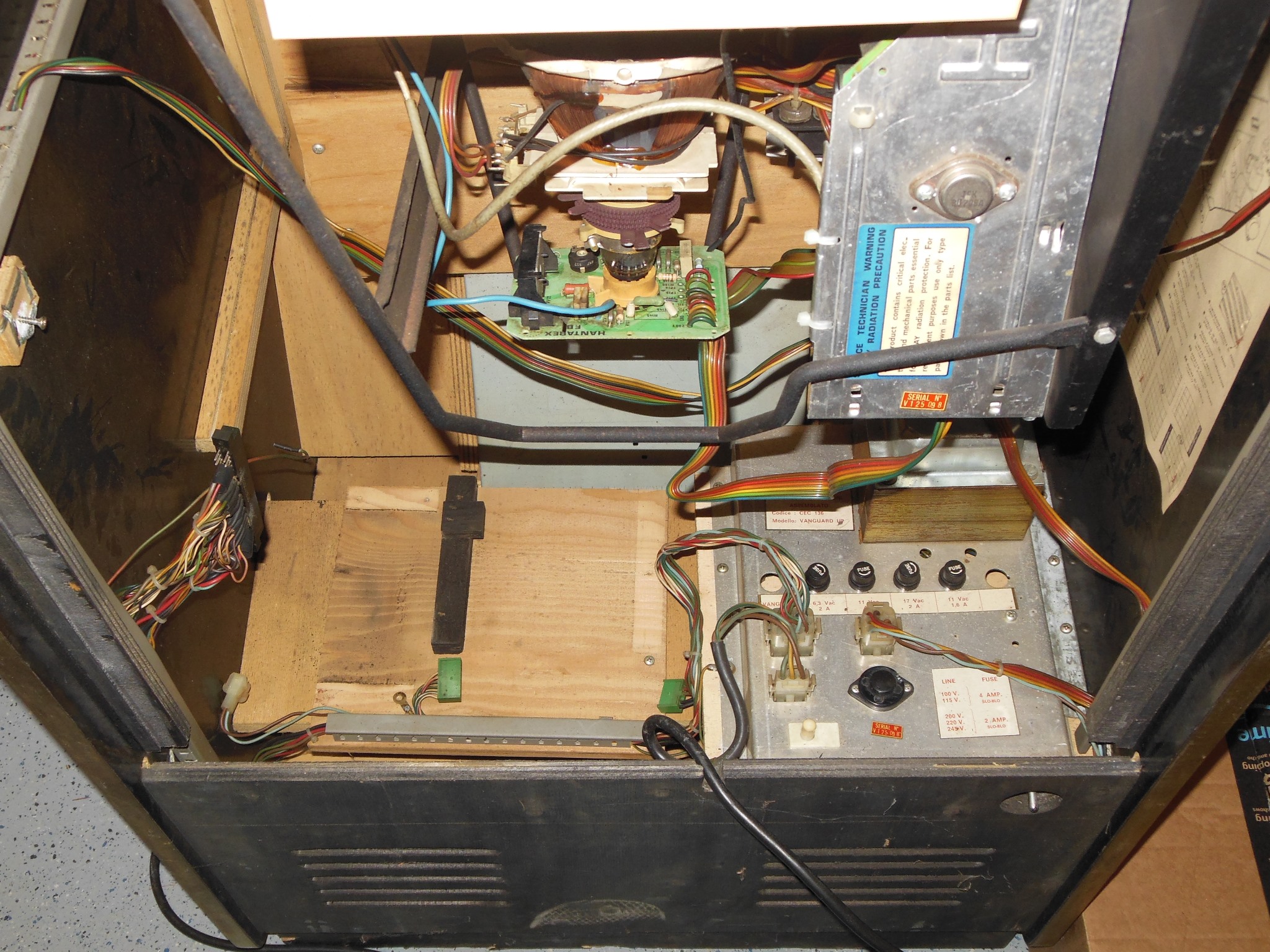
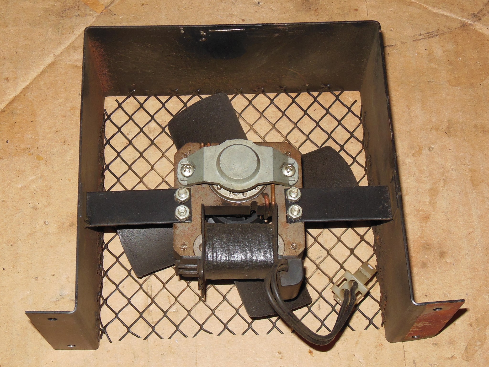
The power assembly had almost no corrosion anywhere, not even the fan grill. The control panel was missing the back cover but the cover was inside the cabinet behind the coin door. The coin door was also in very good condition with all wiring complete and there was a Zaccaria back door key on the ring.
|
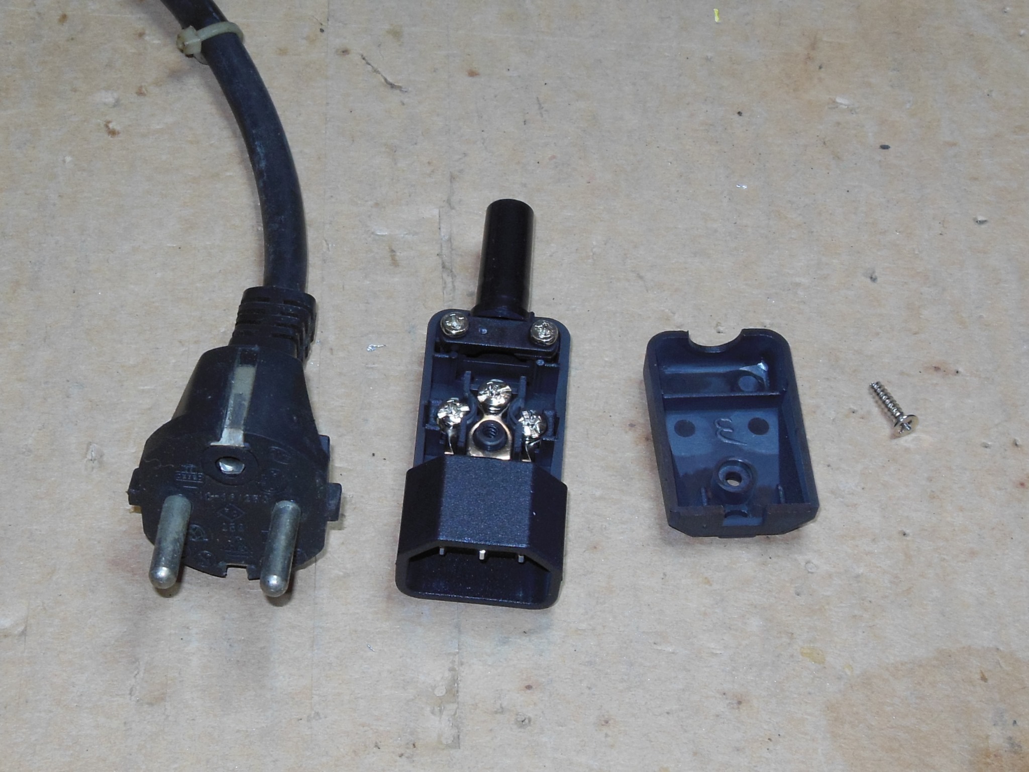
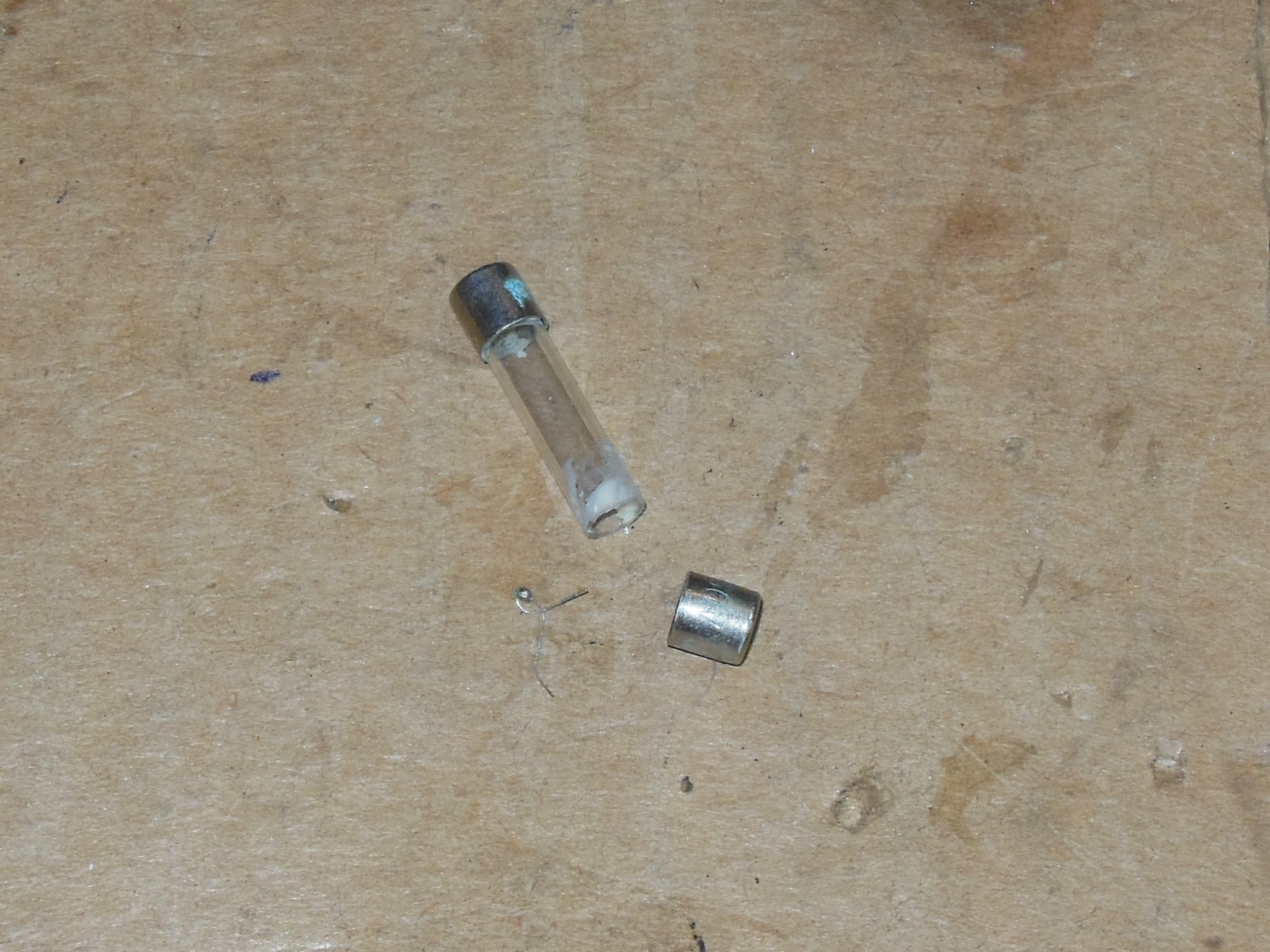
After replacing the mains plug and checking the voltage selector, first power on yielded absolutely nothing. A multimeter confirmed there was no output at all from the power assembly and inspection of the line fuse found it disintegrated. On second attempt at power on the cabinet fan started up but no coin or marque lights and no sign of life from the monitor. There was speaker noise and the game coined up blind OK, suggesting the game PCB was running.


|
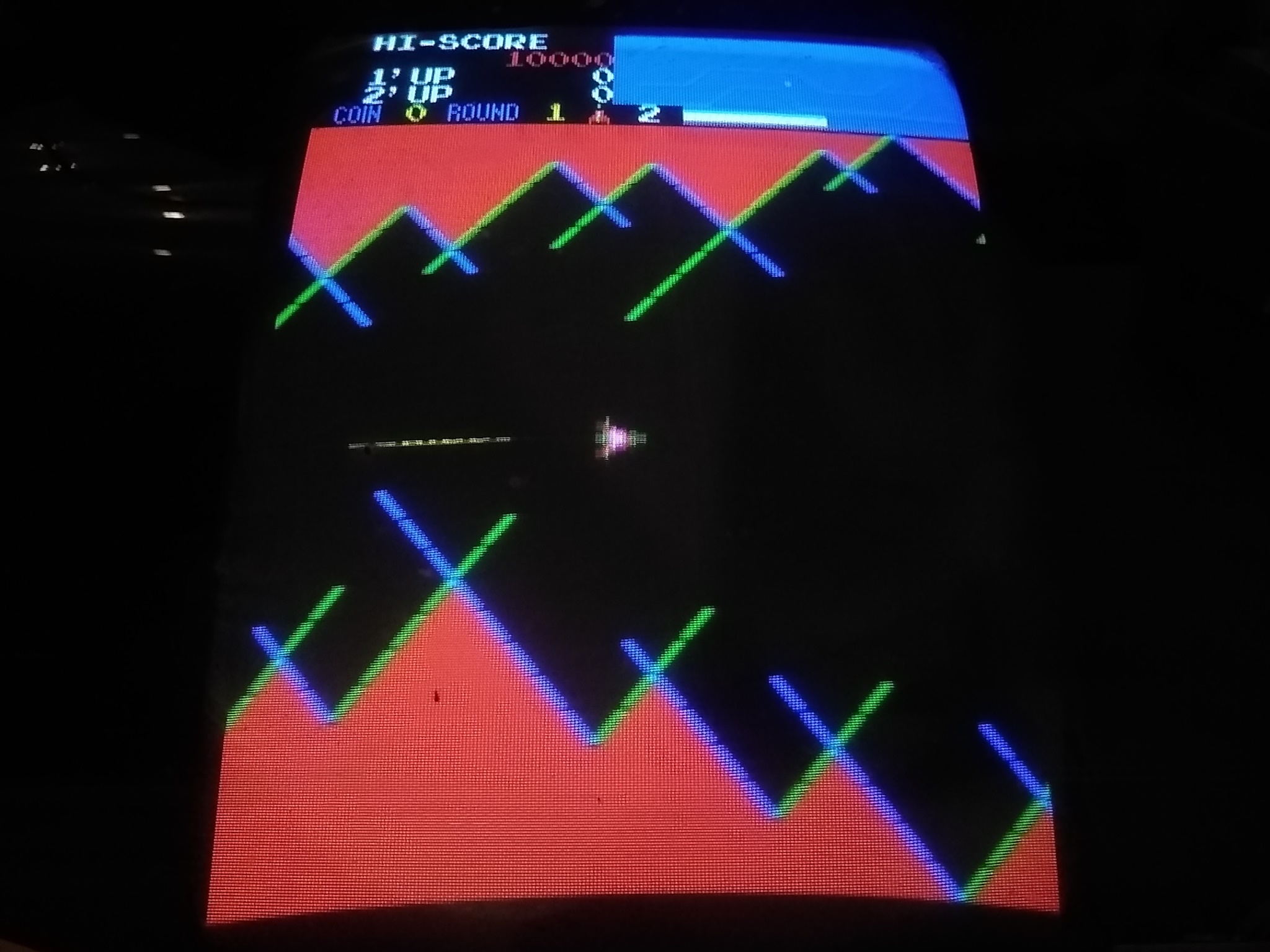
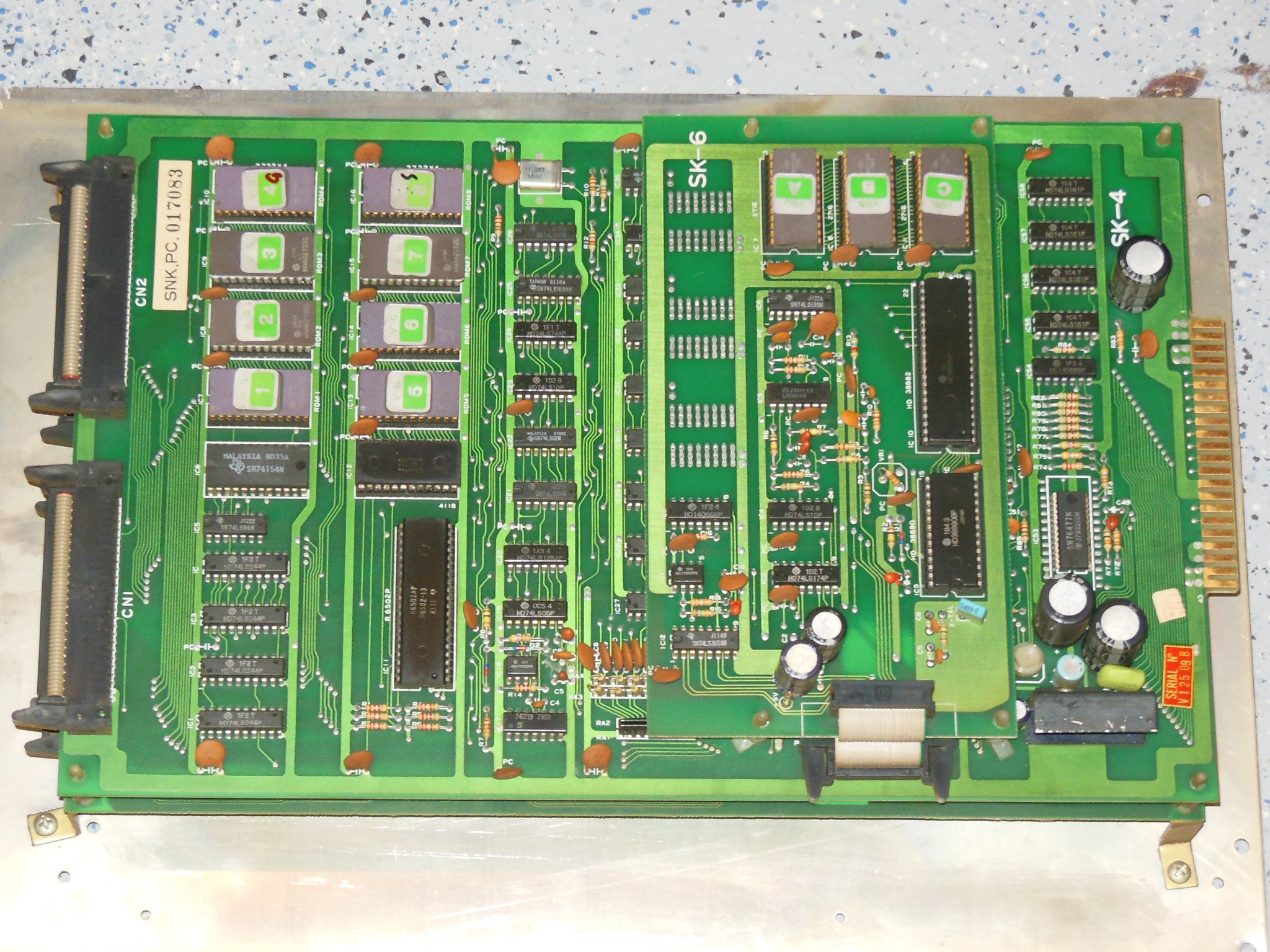
I had a few spare Vanguard game PCB sets in various incomplete states from which I selected the best of the bunch to repair as a spare set for the cabinet. On the bench the spare PCB booted up and played but with graphics problems - the background was corrupt and the colours off. Aside from that, the game played without issue and all the sounds were working.
Flexing the video PCB caused the corruption to change hinting at poor socket contacts. Pressing on IC67 & IC68 (MSM-2128) confirmed they had poor contacts. The IC pins were black & oxidized in places that was unusual because this was a ceramic gold pinned IC. The soft gold pins were carefully cleaned up. Similarly, pressing on IC50 & IC51 (2716) also caused graphics artifacts due to pin oxidation. After cleaning the colours were correct and no amount of flexing or pressing caused any problems so I deferred socket replacements.

|
I'd noticed on coin up in the cabinet that the game had speech, something I'd not known before despite having owned and repaired several PCB sets in the past. Looking at the game PCB in the cabinet and the schematics in the manual confirmed that the top daughter PCB was a speech board and there was a -5V fly lead needed for it to work. I modified my SNK to JAMMA adaptor to add the -5V lead using a crimp spade connector "backwards" to make a socket for the PCB post plug.
The spare PCB ran on the bench for a short while before crashing and no longer booting properly. To fix that would need Vanguard support adding to the Arduino ICT and so the PCB was set aside.

|
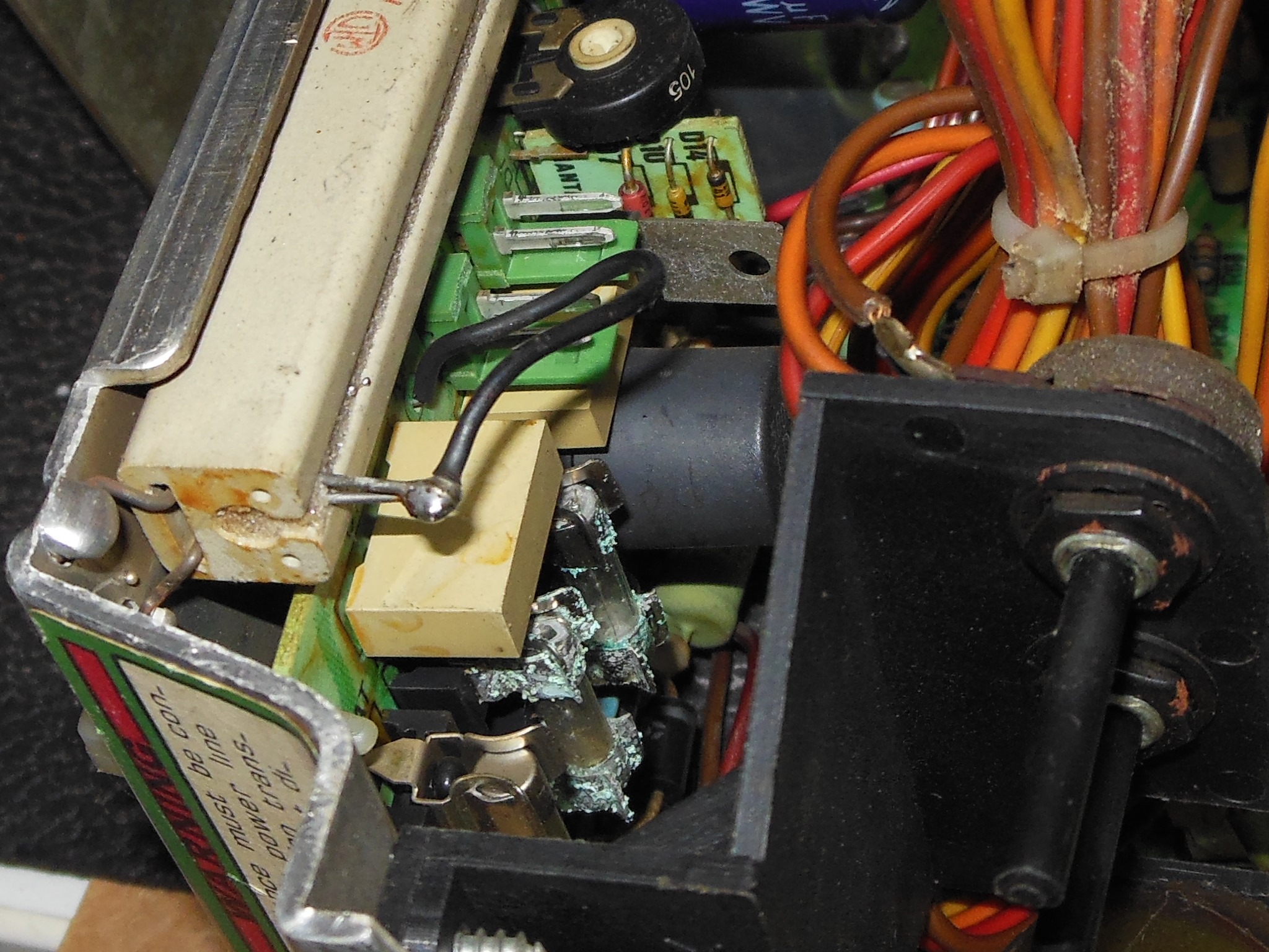
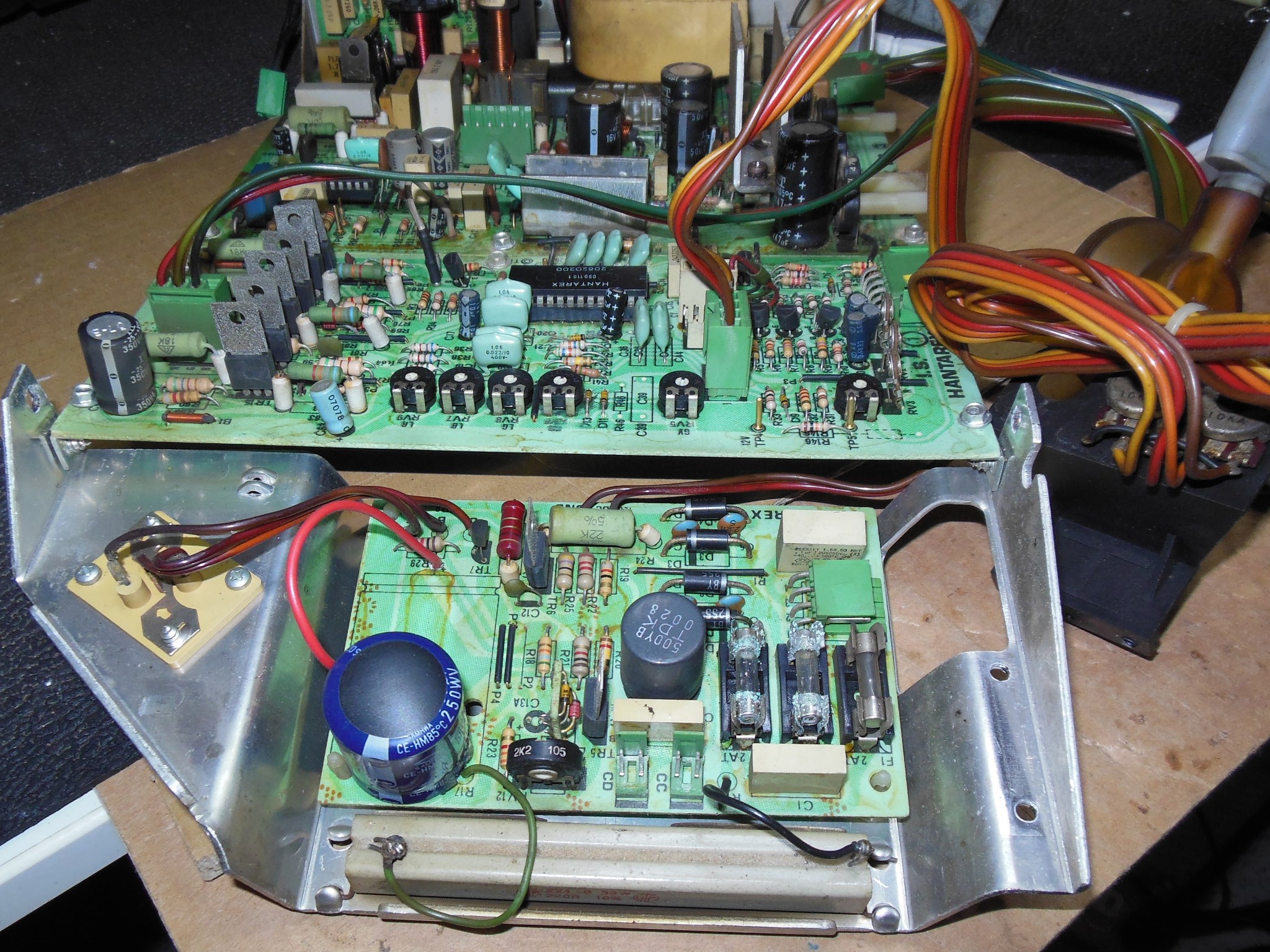
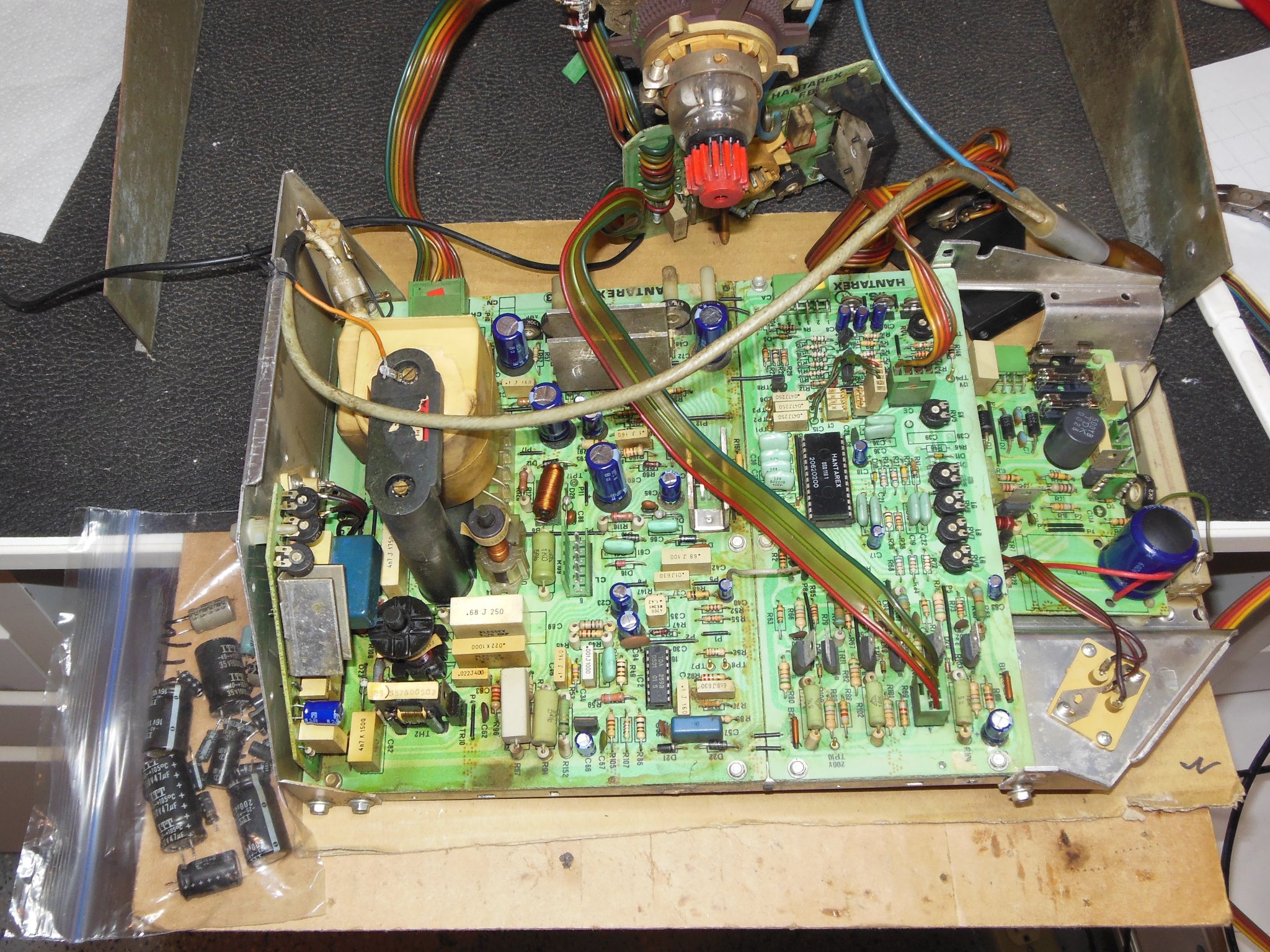
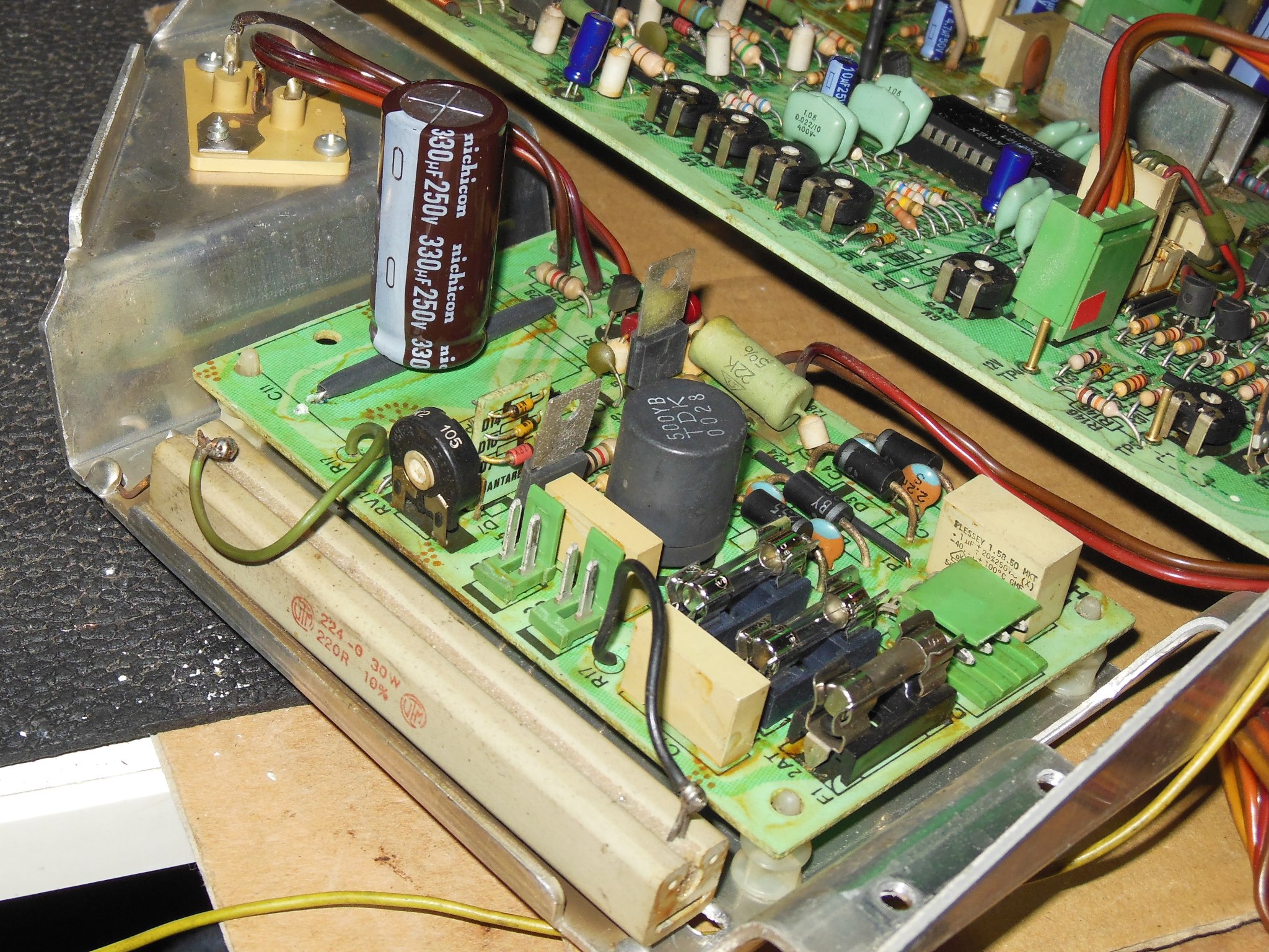
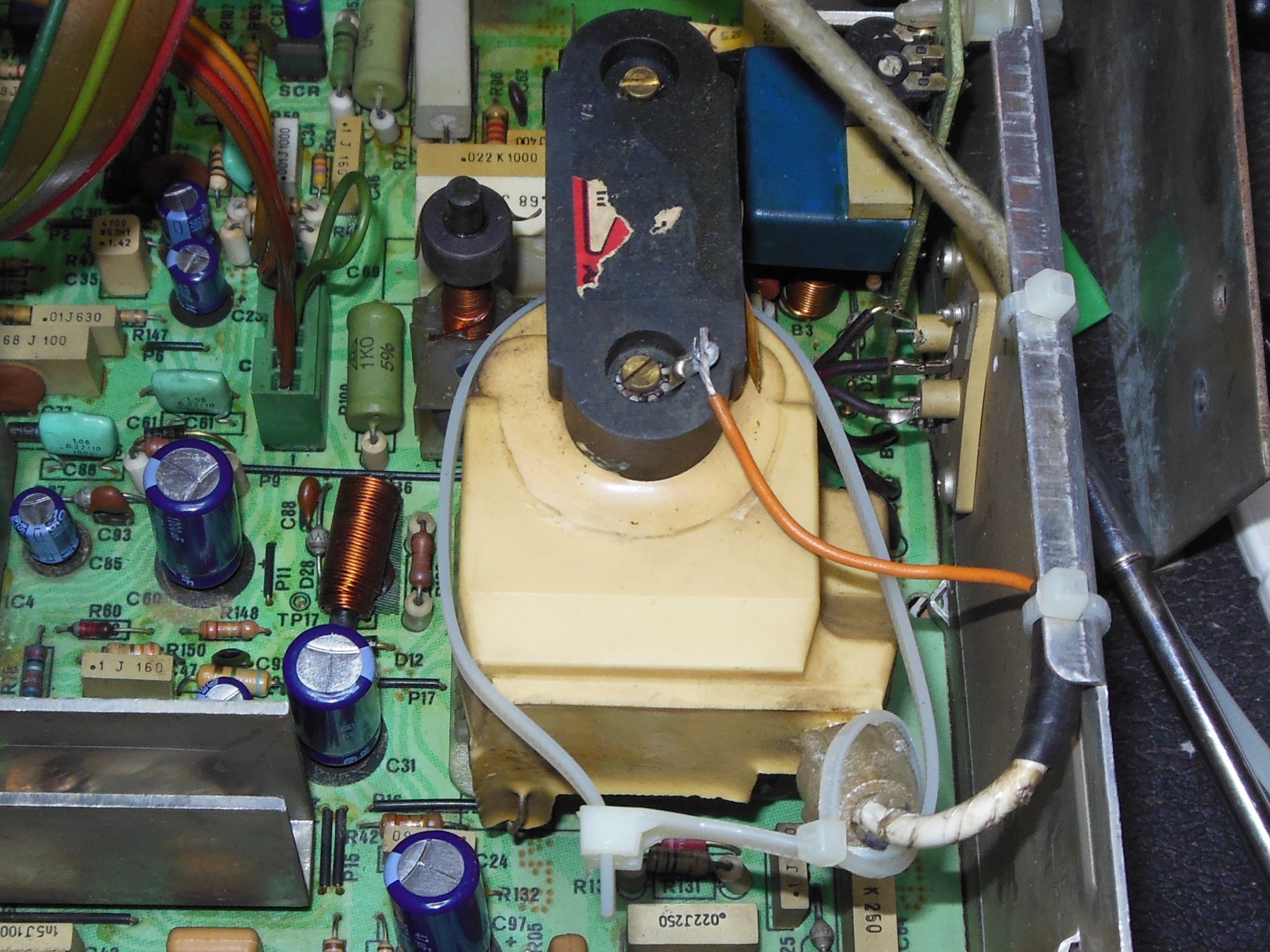
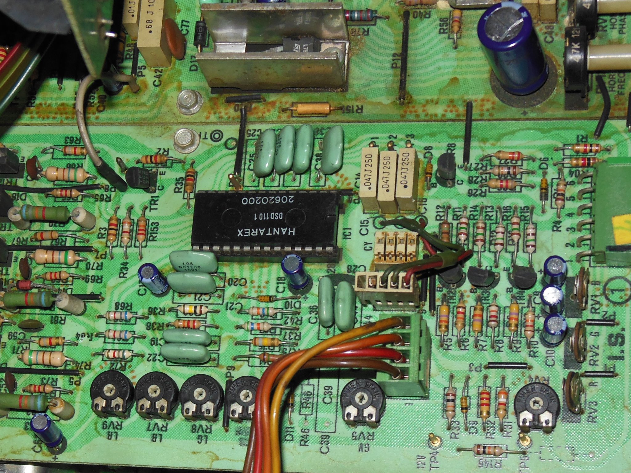
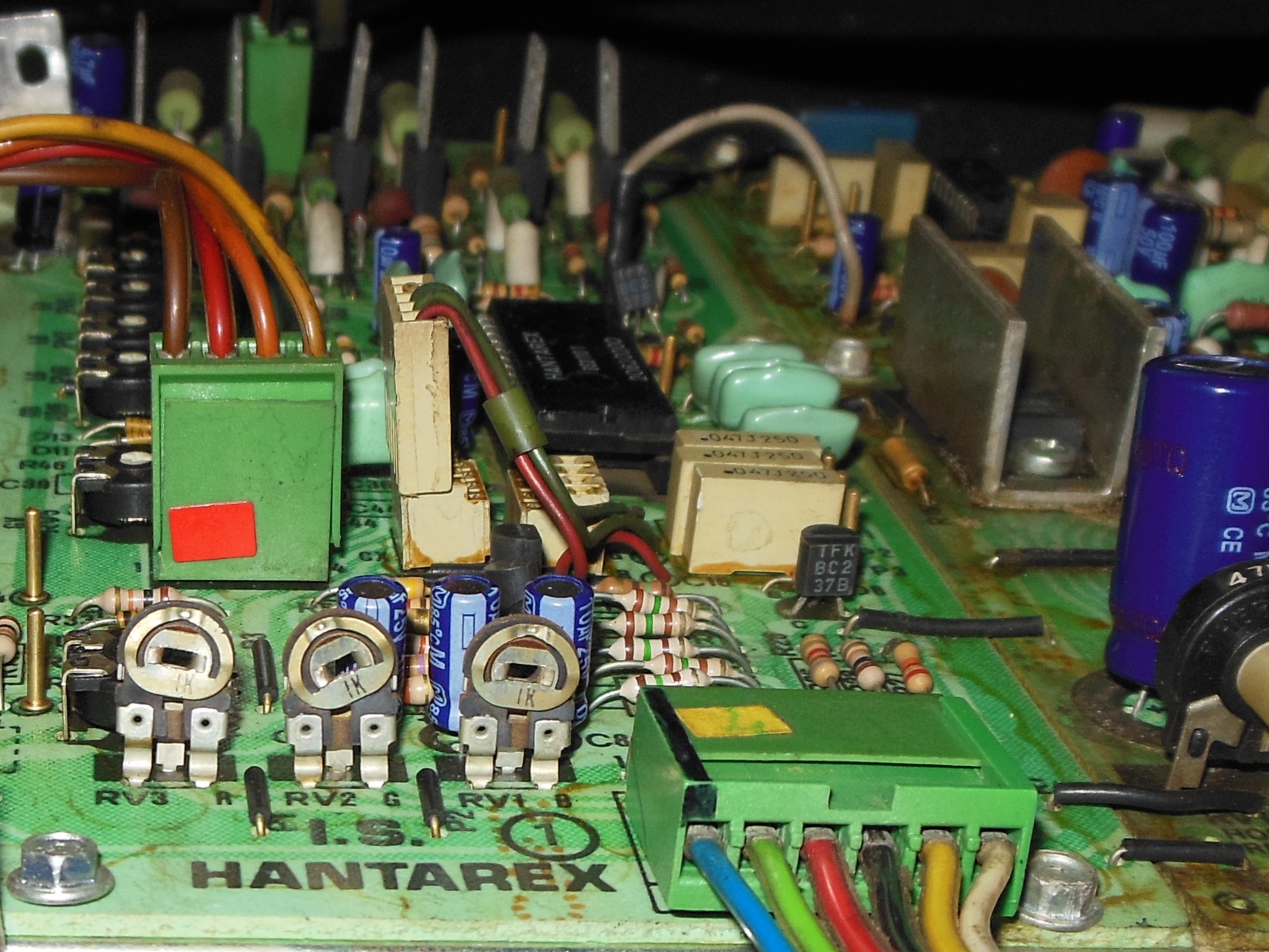
Visual inspection of the Hantarex MTC-900 monitor chassis found three problems to address. First, the HV lead socket on the LOPT was broken. I had very few spares of this LOPT so planned to try it and see if it worked then patch it as best I could. Secondly, the power PCB fuses and holders were corroded. The multimeter confirmed both measured open at the pins. Third, the DC regulation smoothing capacitor was bulging and looked to be a replacement.
|
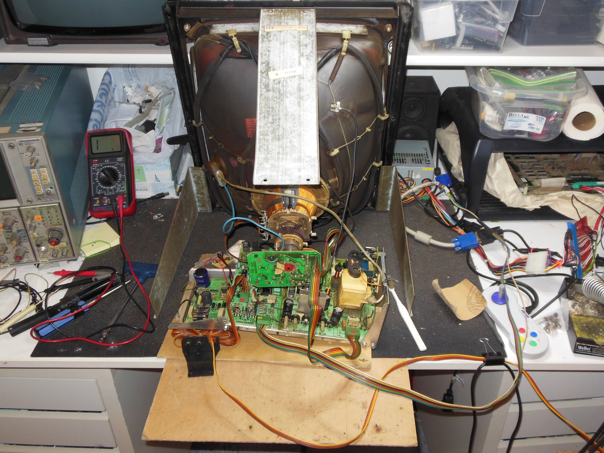
The two line fuses & holders were replaced and the chassis setup on the bench for testing. On power on the chassis came on with a dim picture and ran for a few seconds before a capacitor vented smoke somewhere and I cut power. Time for a cap kit.
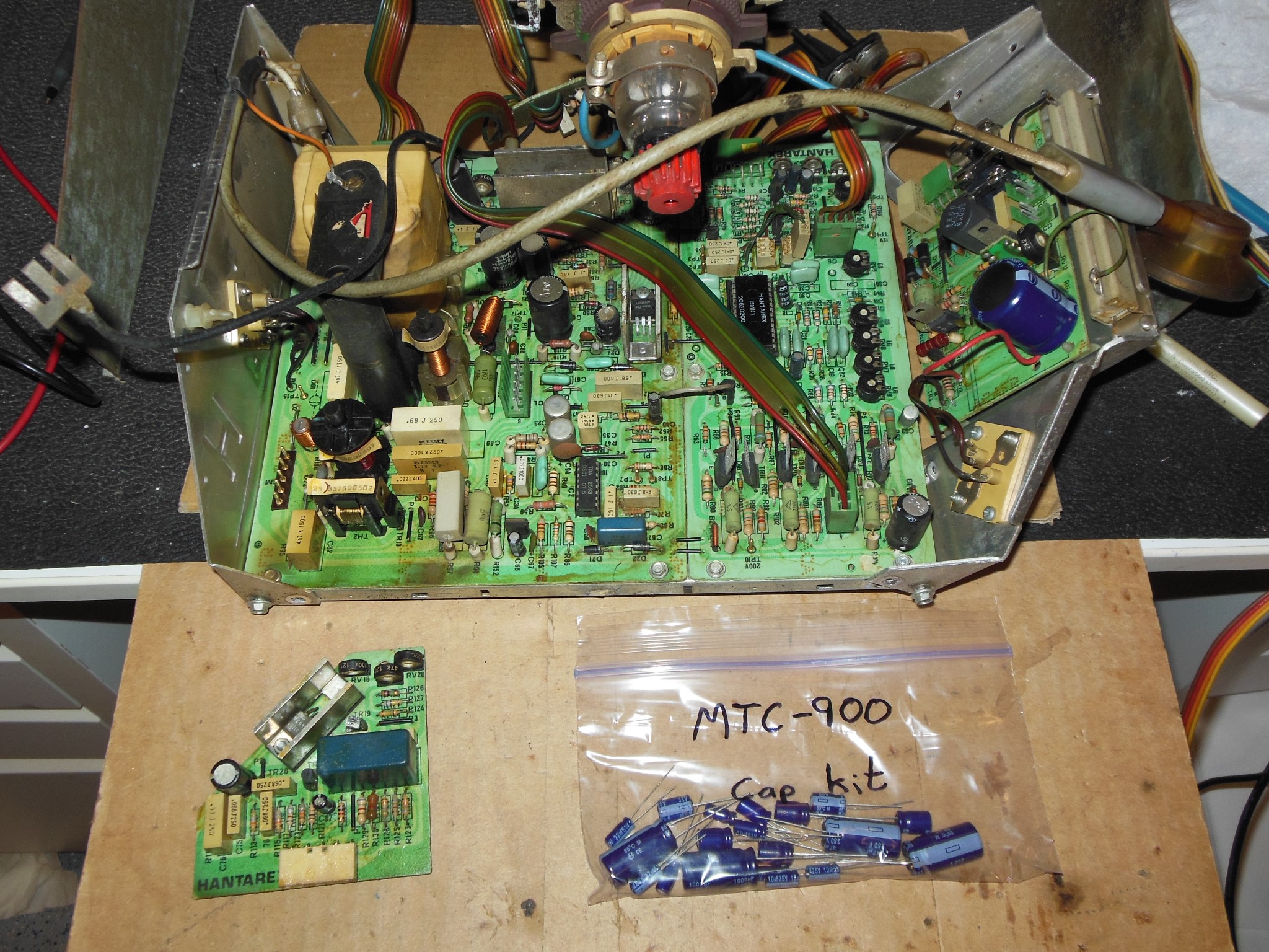
|
After the DIY cap kit was fitted, power on yielded a stable picture with colours a bit mushy. The damaged LOPT had a little hiss in it but was otherwise working OK.
|
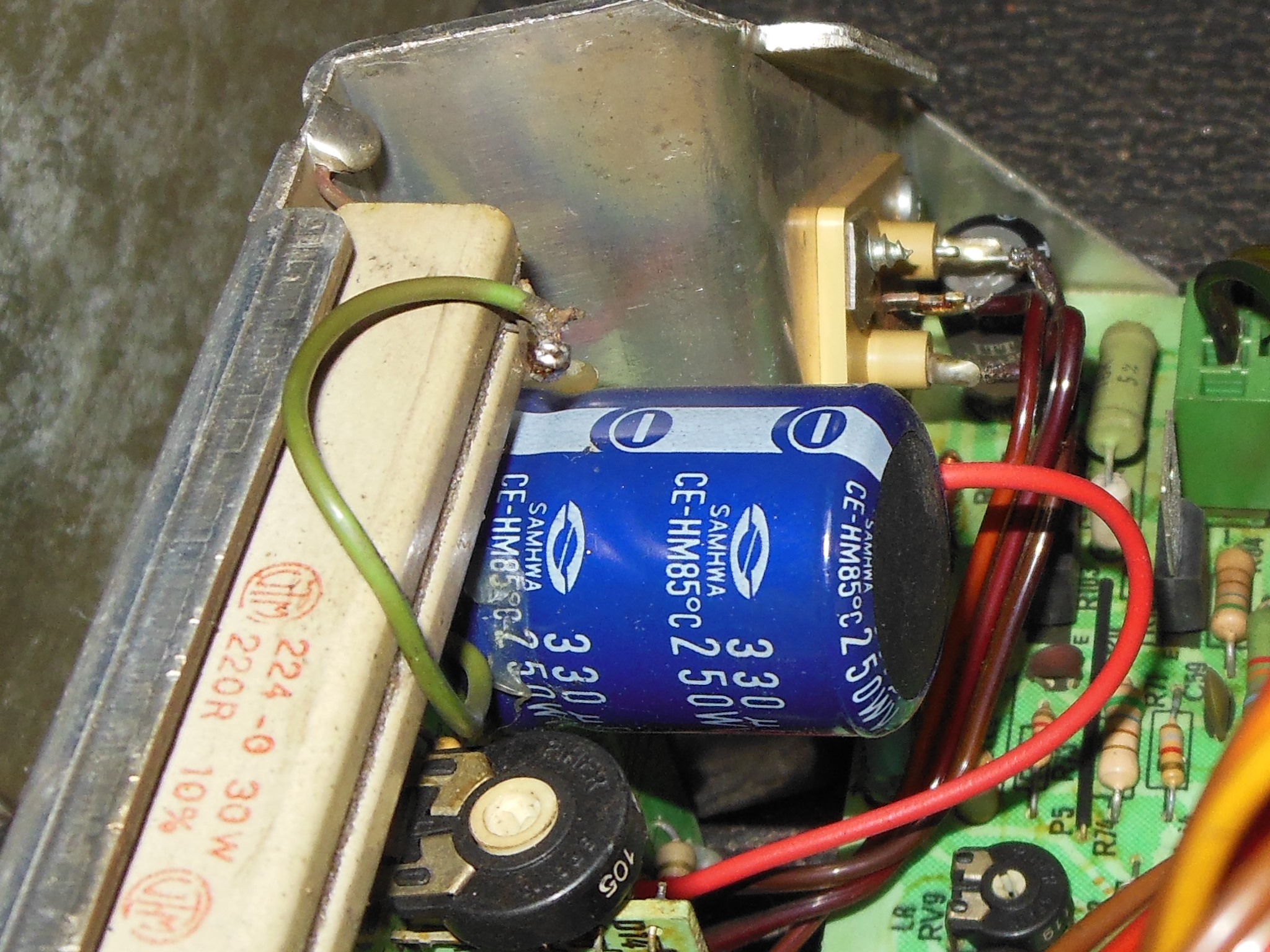
The large power regulation cap on the power PCB wasn't something I'd replaced previously and axials were not easily available so I'd had to order vertical replacements. The leads on the vertical replacements were slightly too short to reach the existing axial holes so a new hole and pad was made to fit.
Super glue was used to secure the broken LOPT HV socket along with an arrangement of cable ties to hold it in place.
|
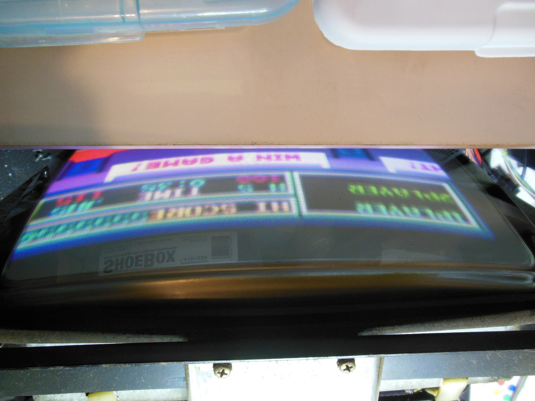
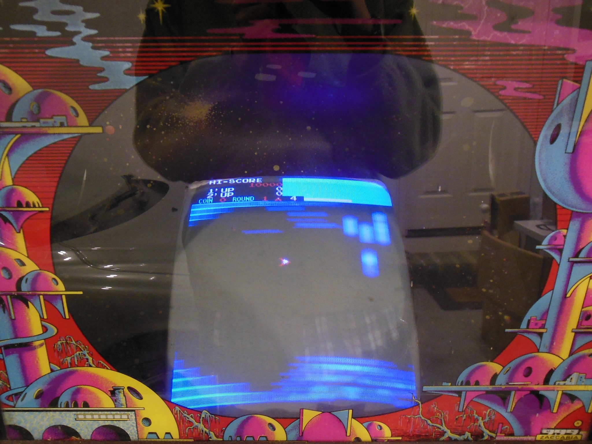
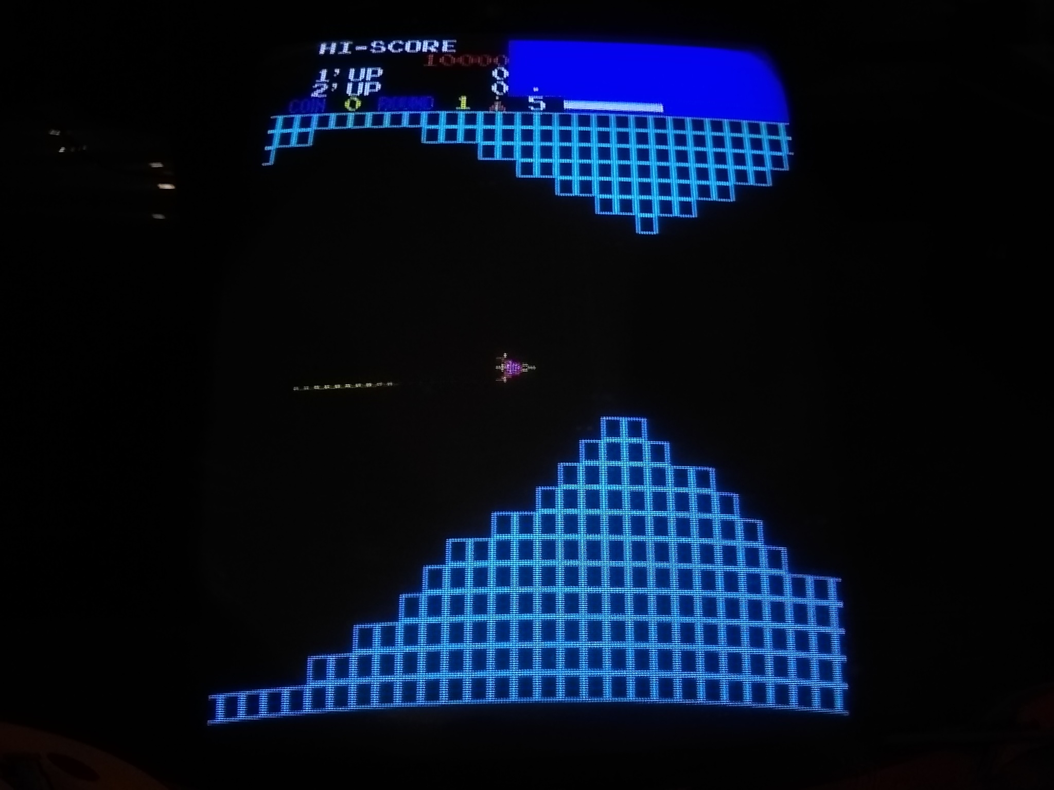
Back in the cabinet the monitor chassis powered on OK to reveal a seemingly working game PCB. The picture colours still seemed a bit off, however.
|
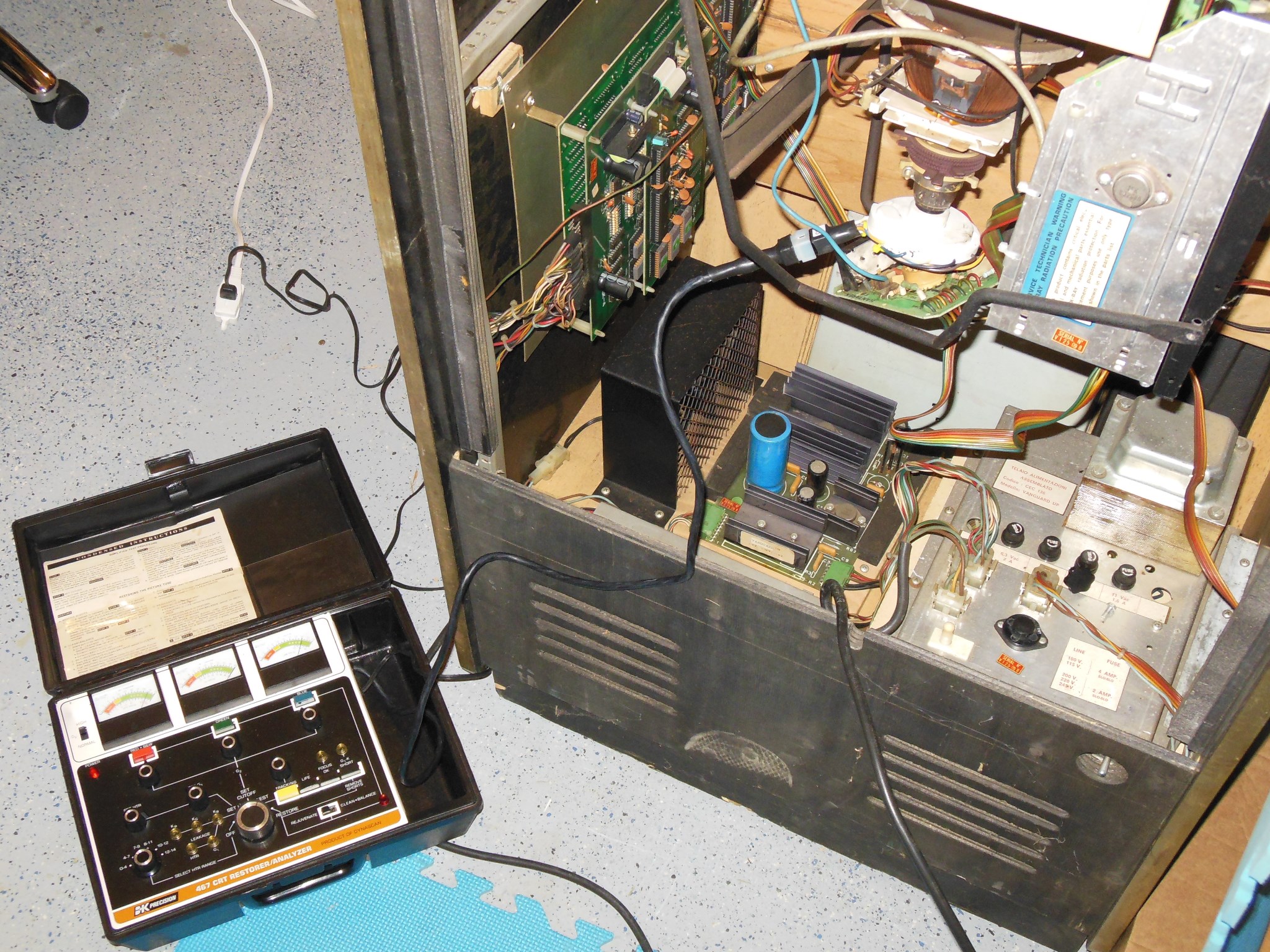
A rejuvenator measured the CRT as good and all guns strong with consistent drive so I suspected a colour balance adjustment was needed on the chassis. Recently I'd been using the scope to directly measure the gun drive at the CRT in order to set an exact colour balance on the bench.
|
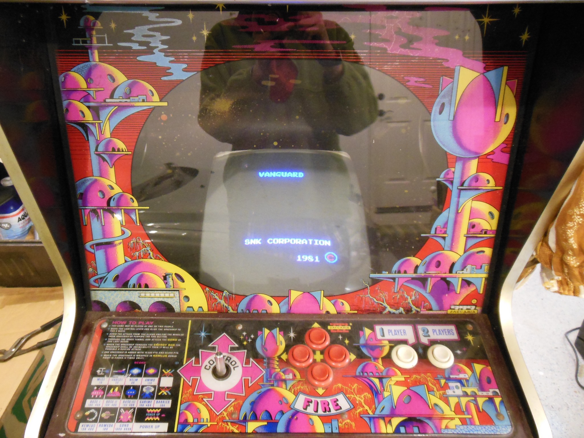
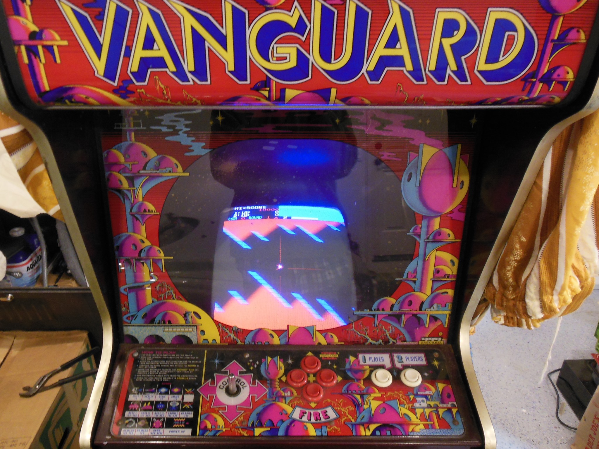
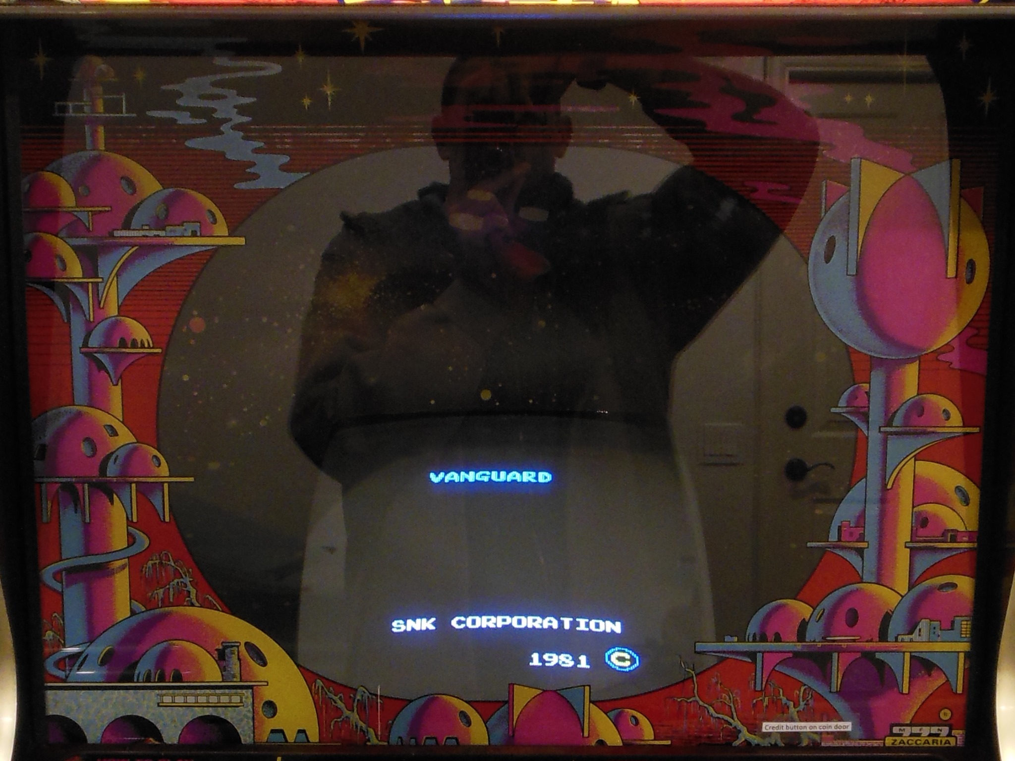
Back in the cabinet the colours looked good.

|
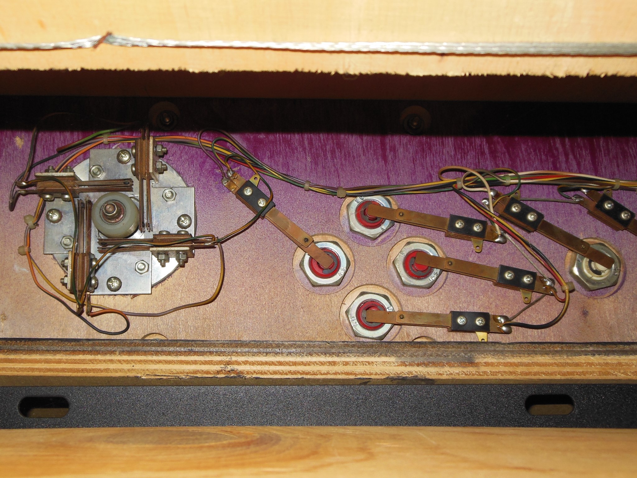
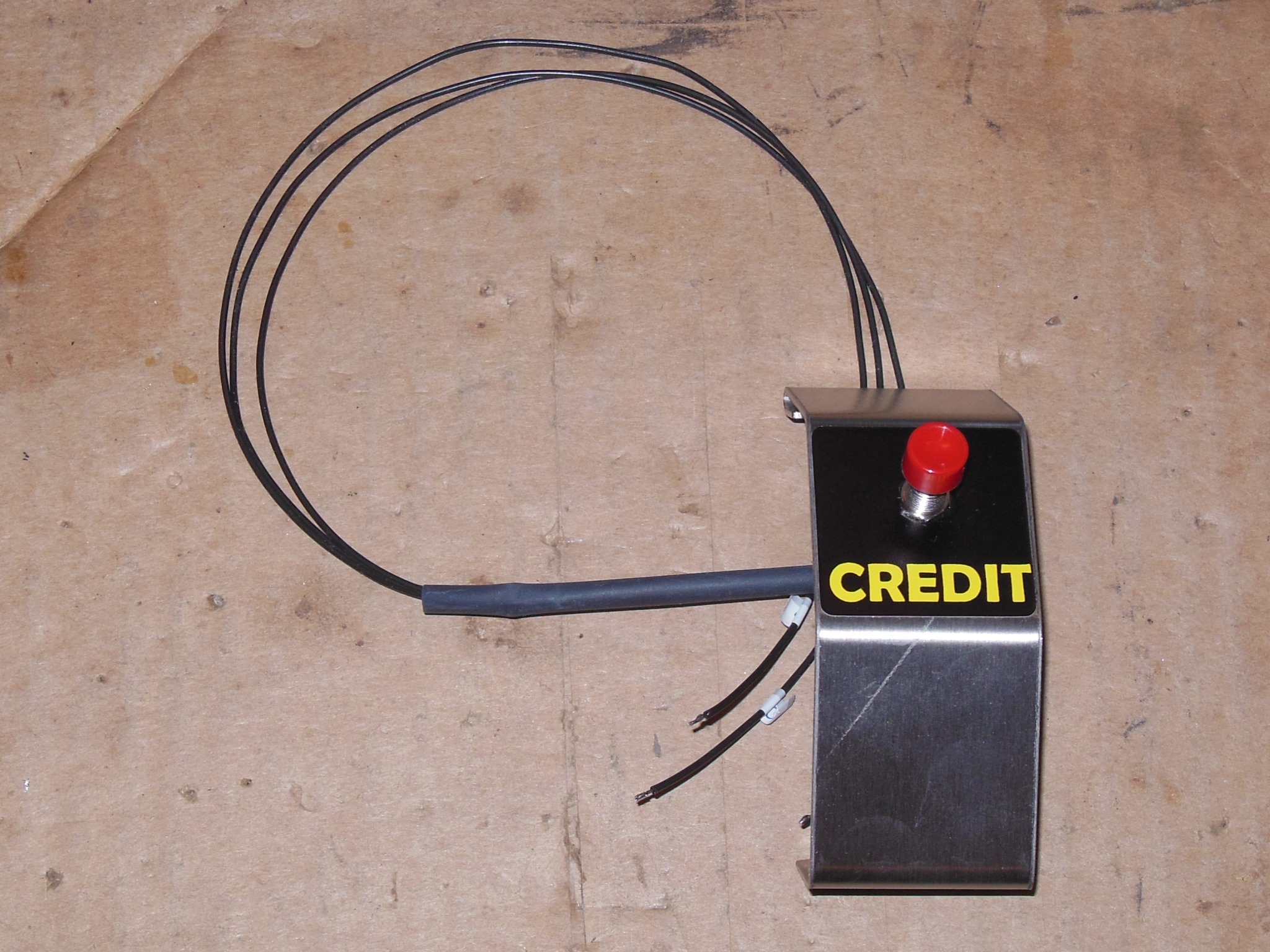
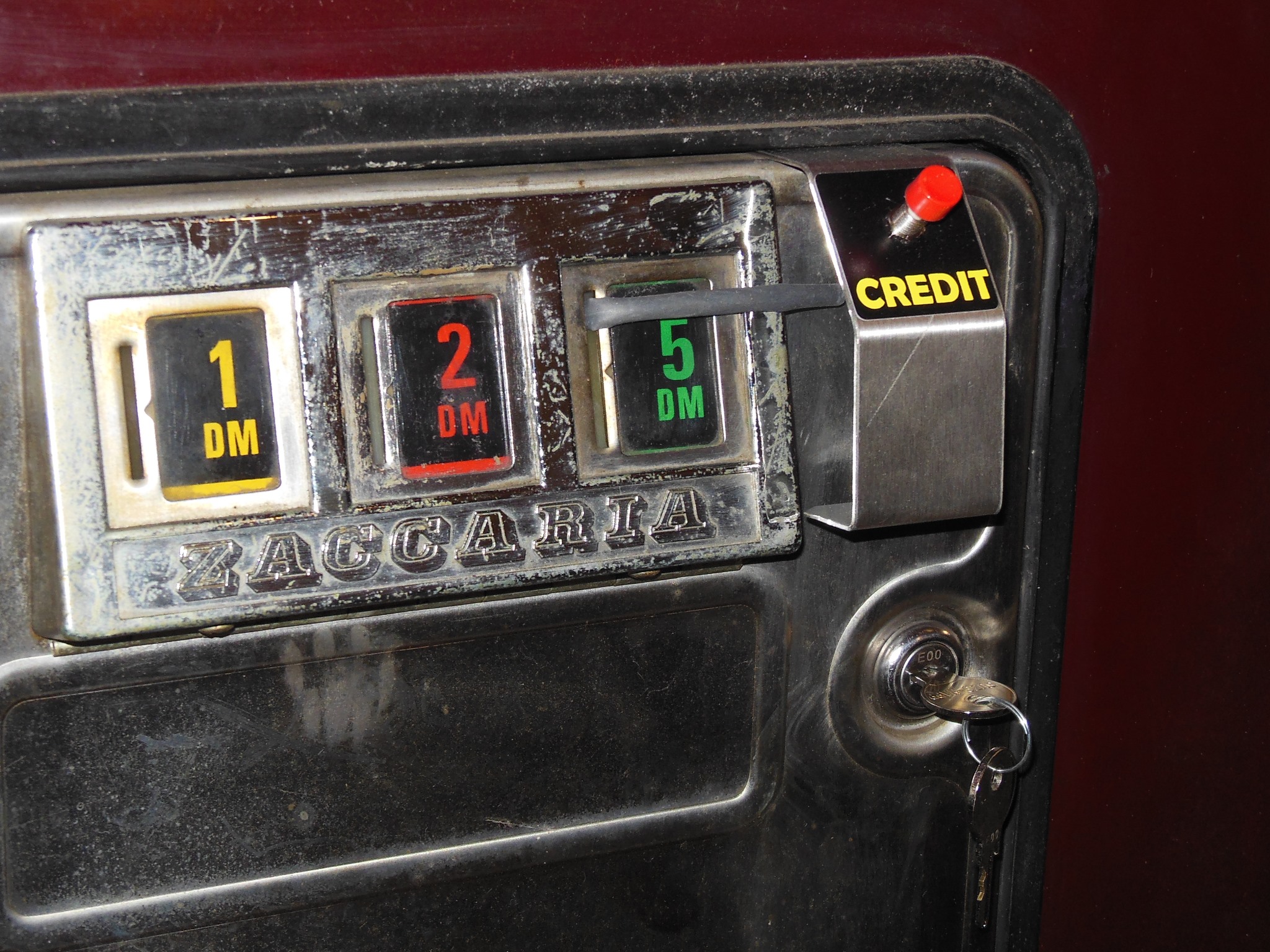
The burnt out coin door lights were replaced and a credit button assembled to go on the front. The credit PCB had a "wire strap" modification to add support for the third slot as 1 coin 1 play that I left as is to match the door configuration.
|
The credit button was fitted and wired into the coin switches.
|
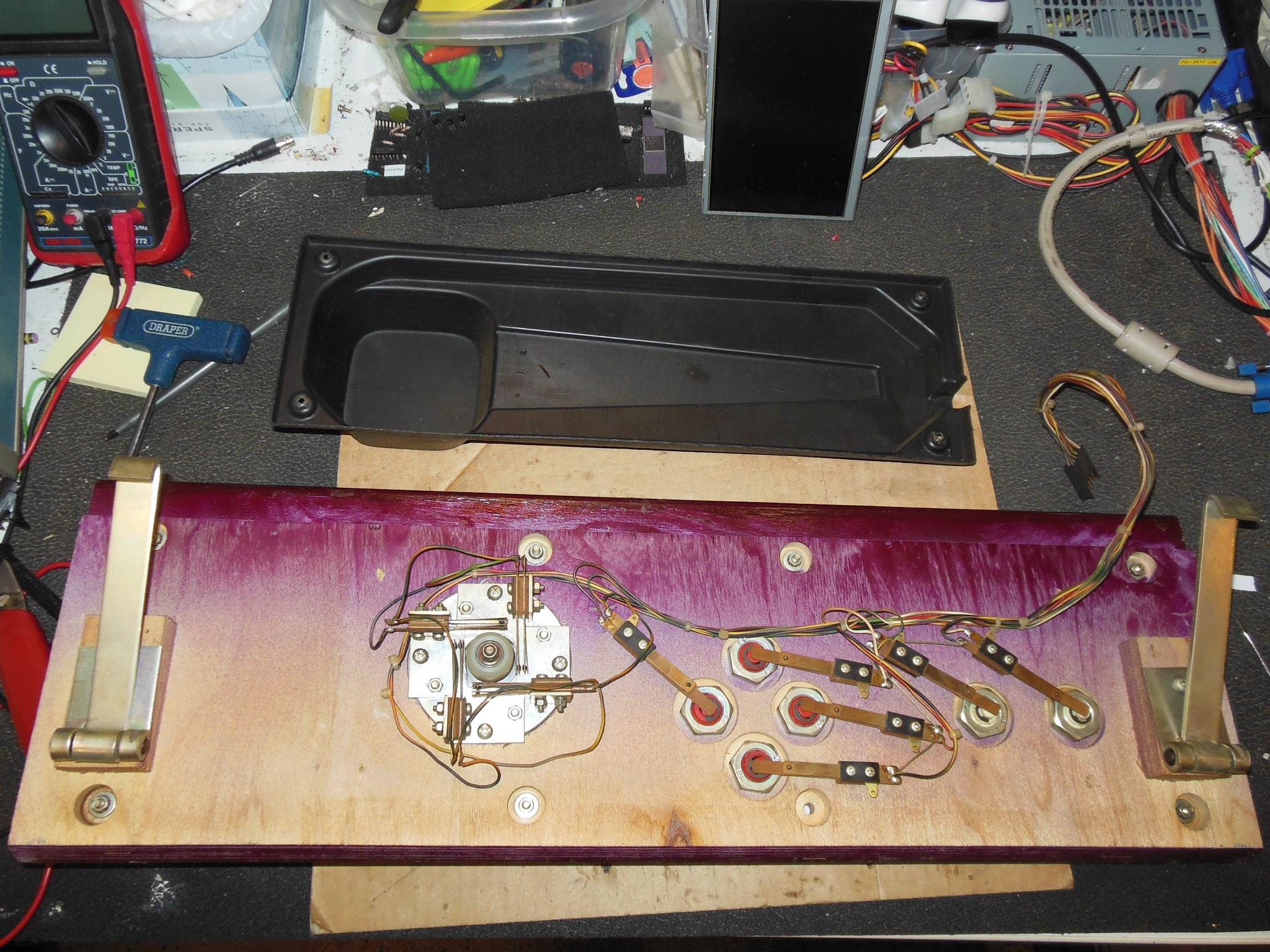
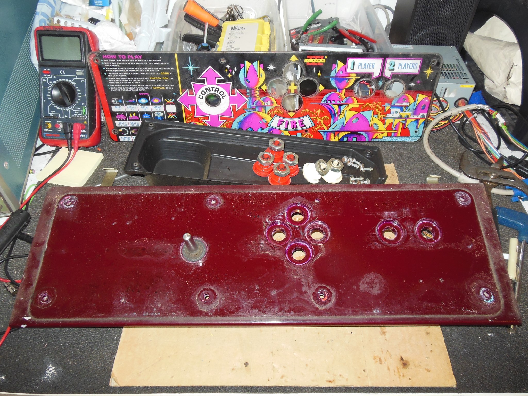
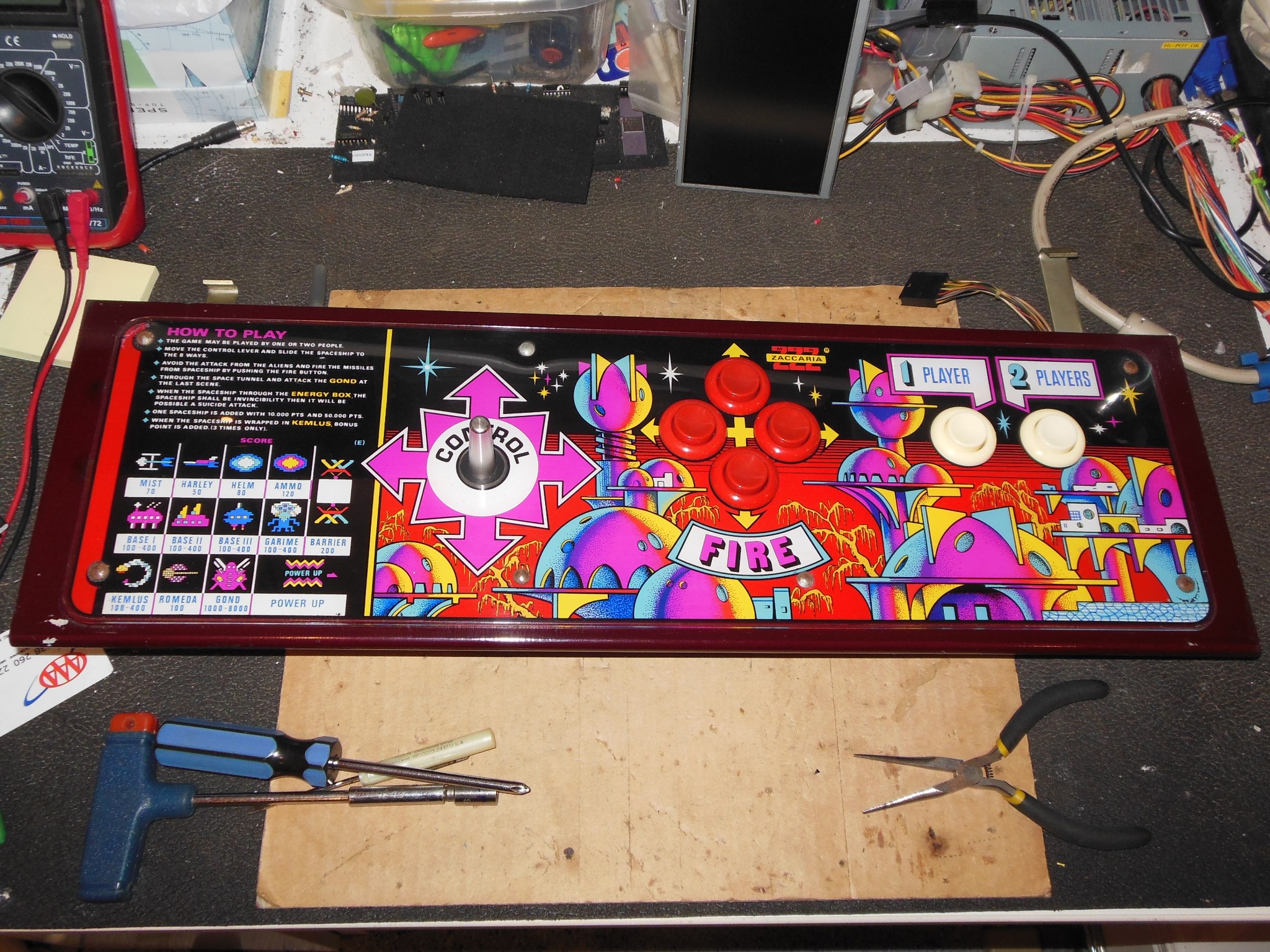
The control panel was removed and disassembled for cleaning & scanning. The overlay was in very good condition, very little paint peeling and only dirt on the paint.
|
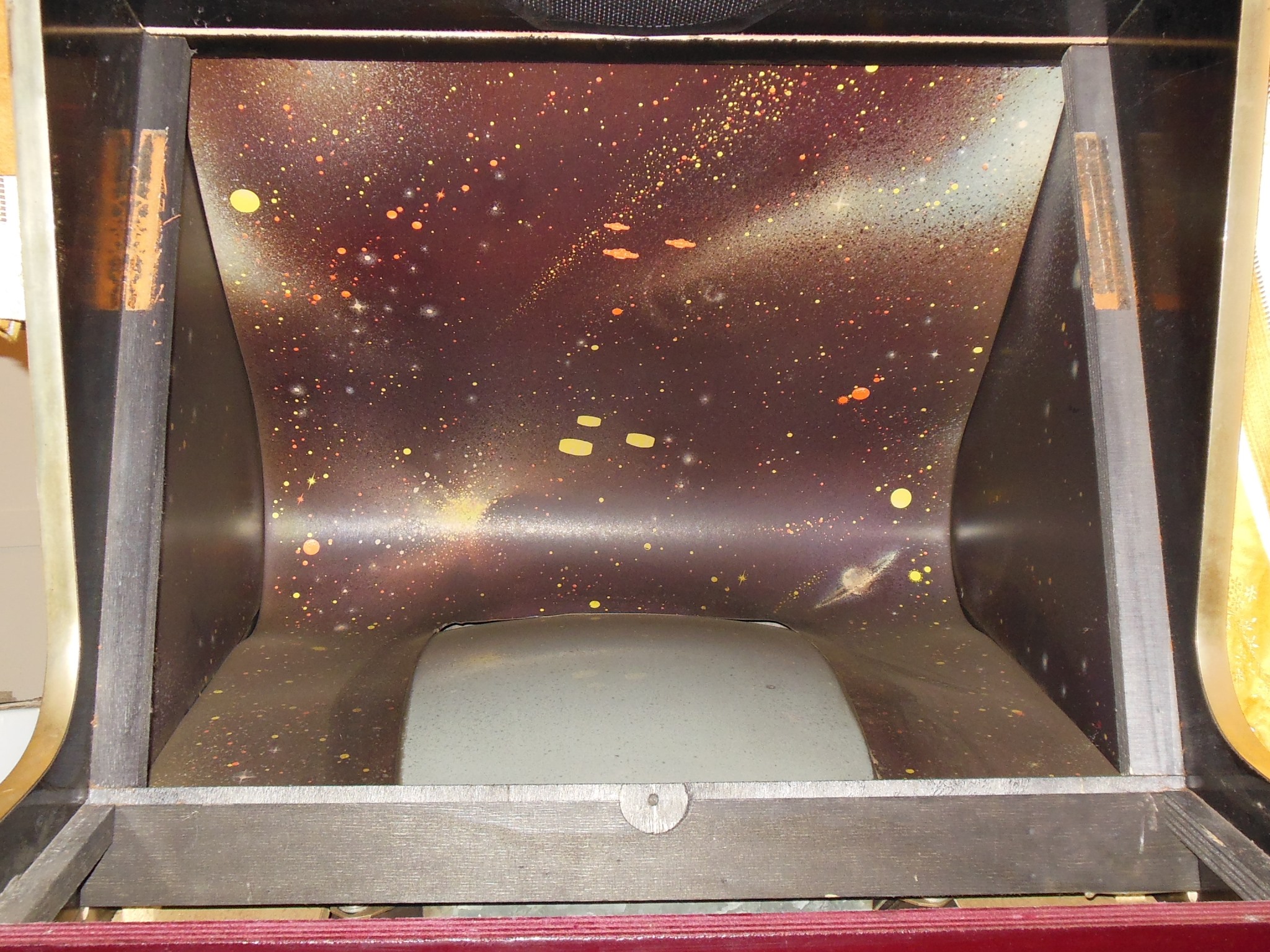
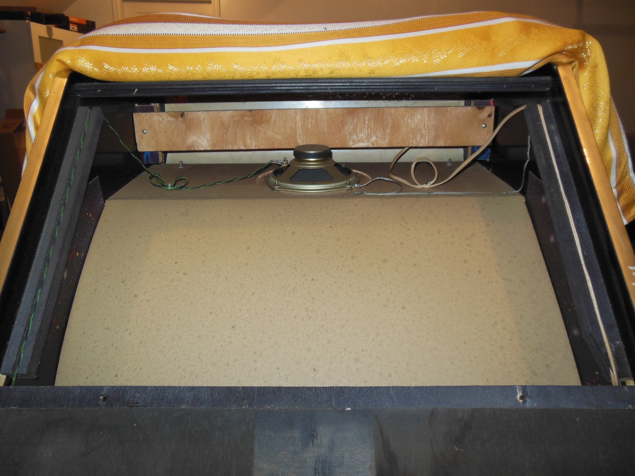
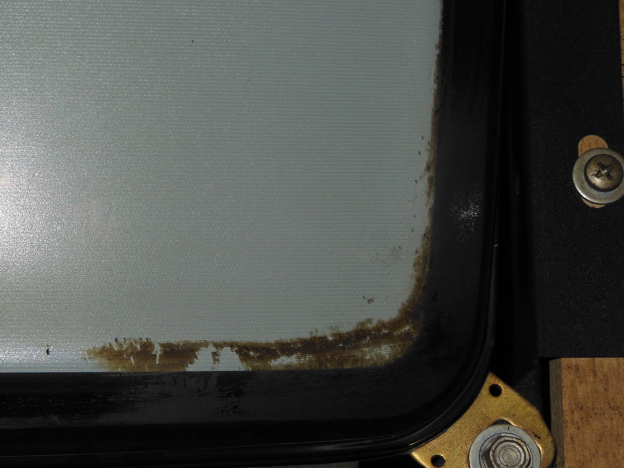
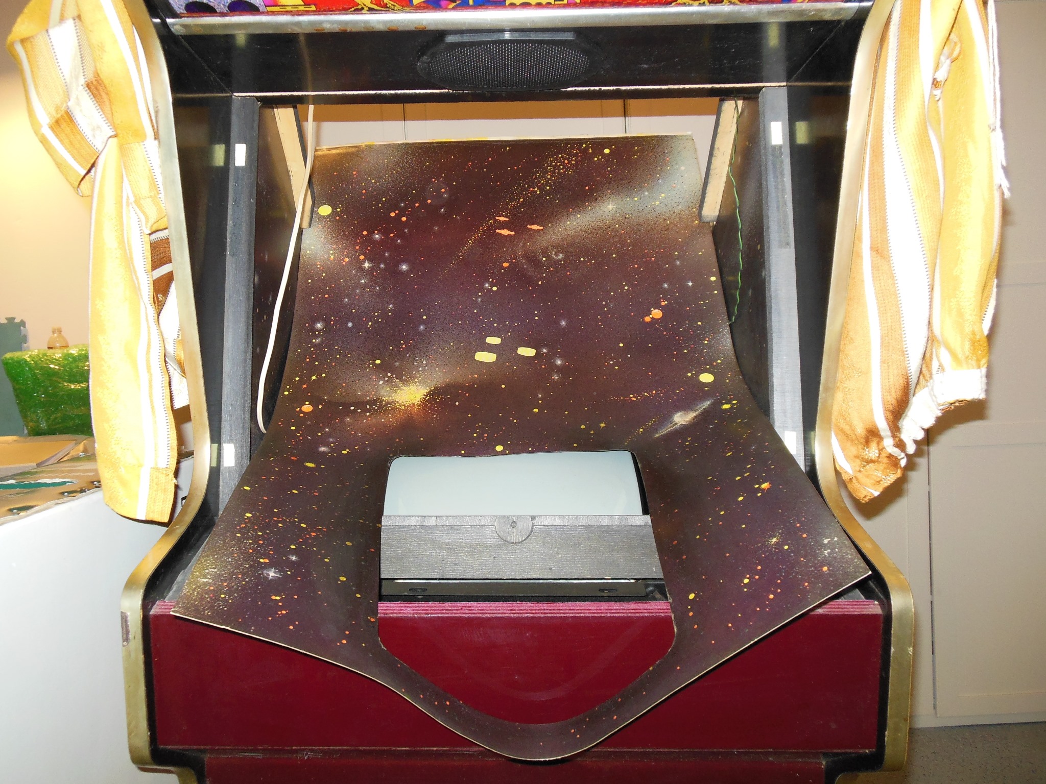
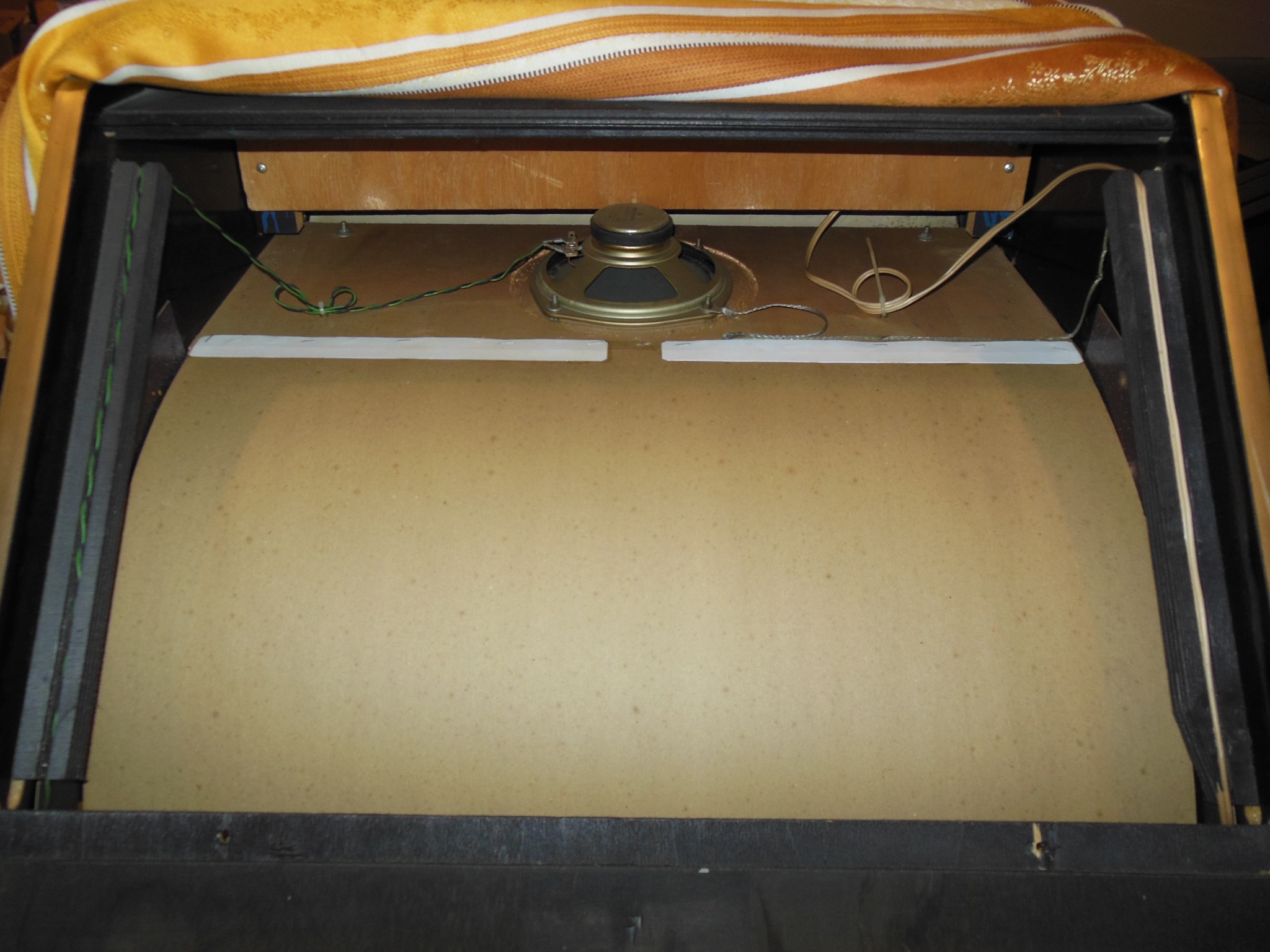
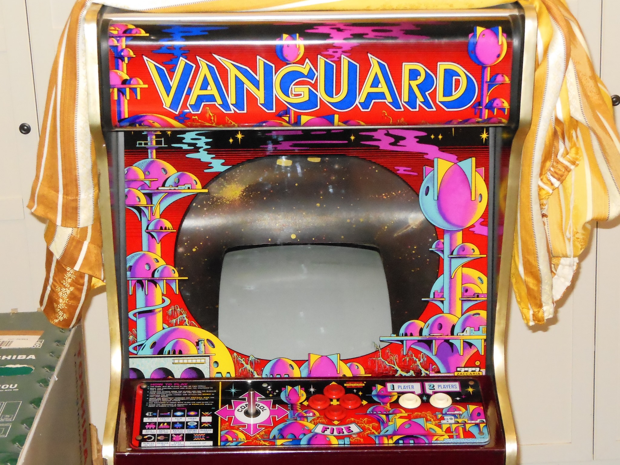
The monitor glass was removed for cleaning & scanning. The glass was in very good condition, no flaking and only nicotine, dust and foam residue on the paint. The monitor surround was also in good condition, no tears or creases and only dust, nicotine at the edges and sagging in the cavity.


|
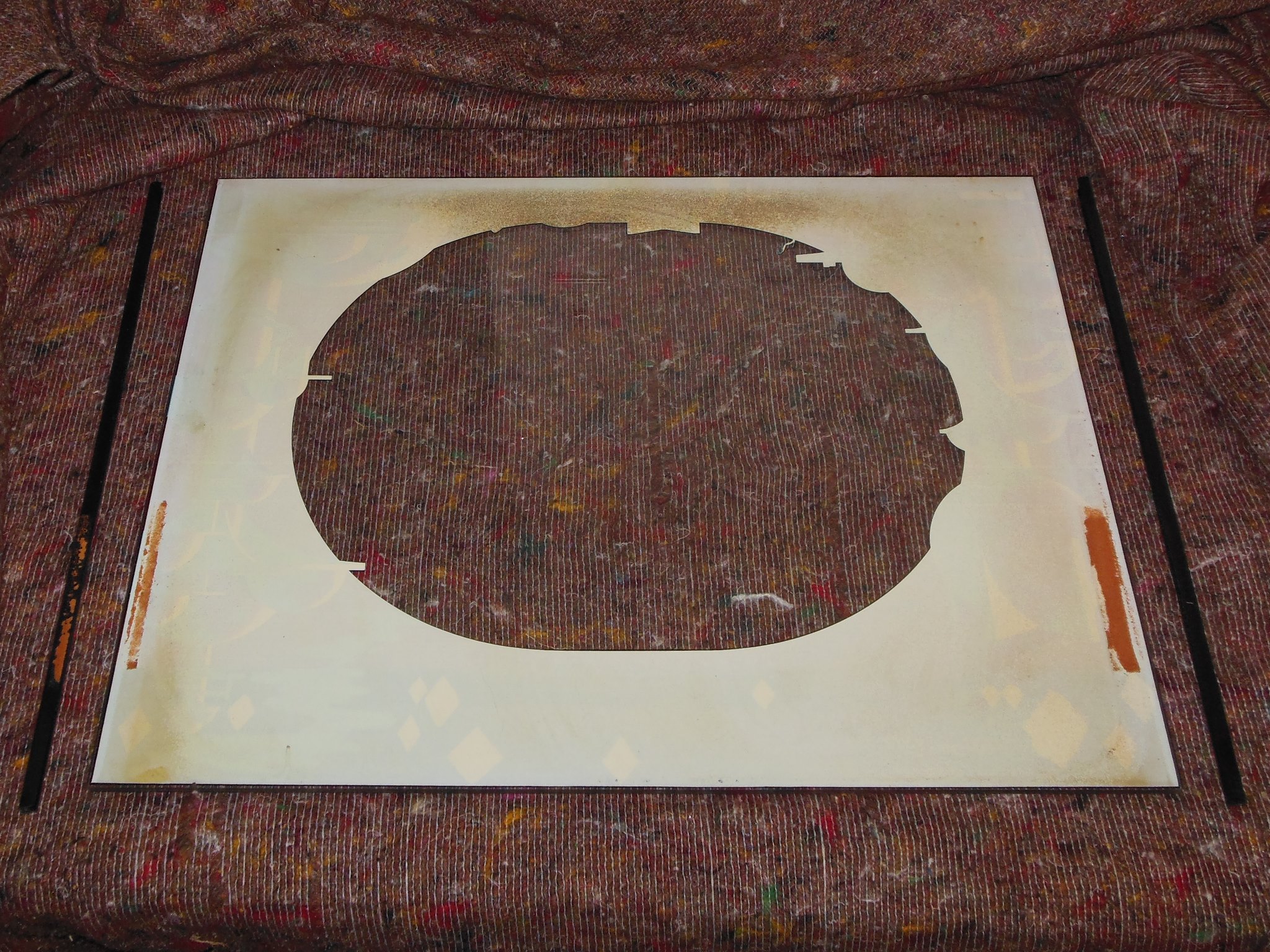
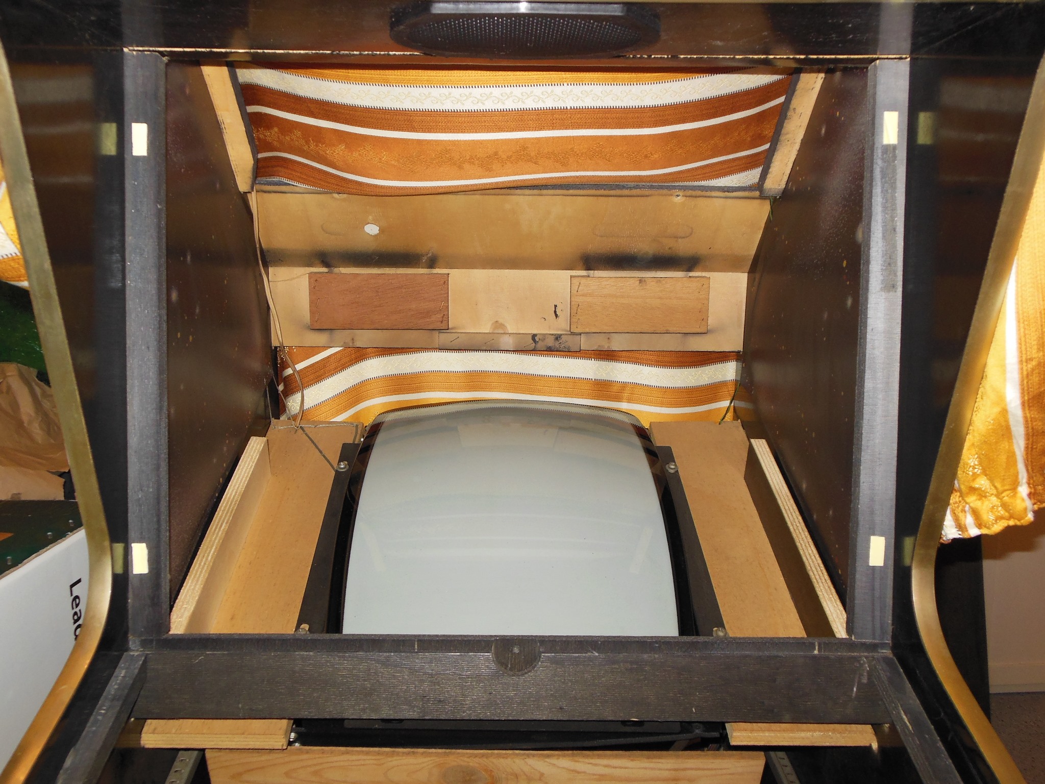
It was a close call to clean the surround in place rather than removing it but on opening the rear top hatch I found that the surround had cracked all along the top seam, causing the sag, that would need removal, flatten & repair. The monitor surround was carefully unstapled and removed.
The back of the surround was first dry dusted and then wiped over with a damp cloth before being to set to flatten for a few days. The thick nicotine residue around the CRT cut-out I left as is.

|
A new tube & starter fixed the marque light.
|
Though the cabinet was in excellent condition overall, it had seen substantial time in a smokey environment that had left the now familiar thick nicotine residue on the CRT. I still hadn't found any easy way to remove it - all the cleaning wipes, Goof Off, sticker remover, bleach or vinegar suggestions hadn't really had much of an effect on it. This time COVID-19 had brought Clorox Disinfecting Wipes into the house that unexpectedly made forward progress on the stains with elbow grease to at least get rid of the stains in the picture area of the CRT.
Four replacement foam spacers for the glass were also cut and fitted.
|
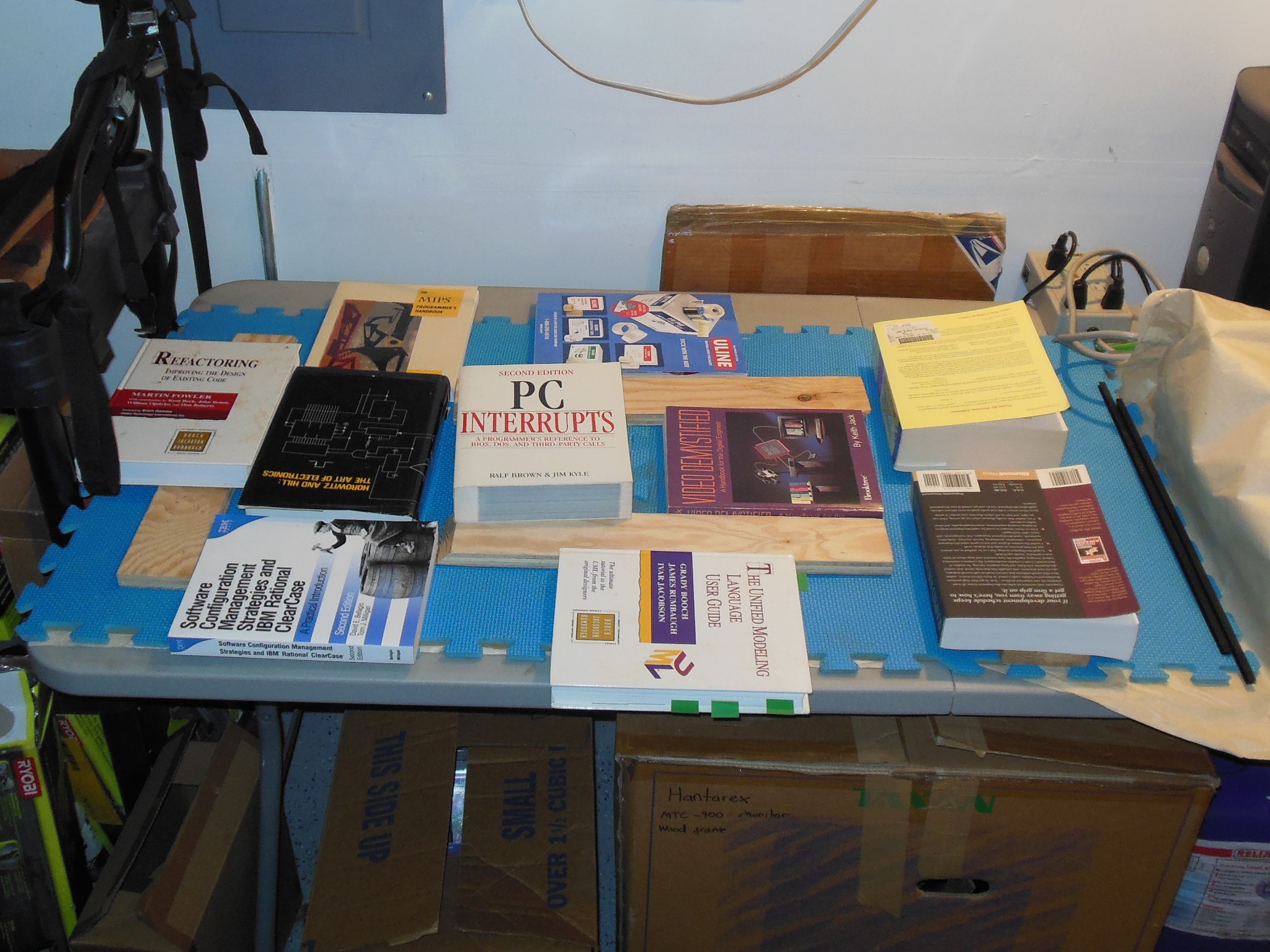
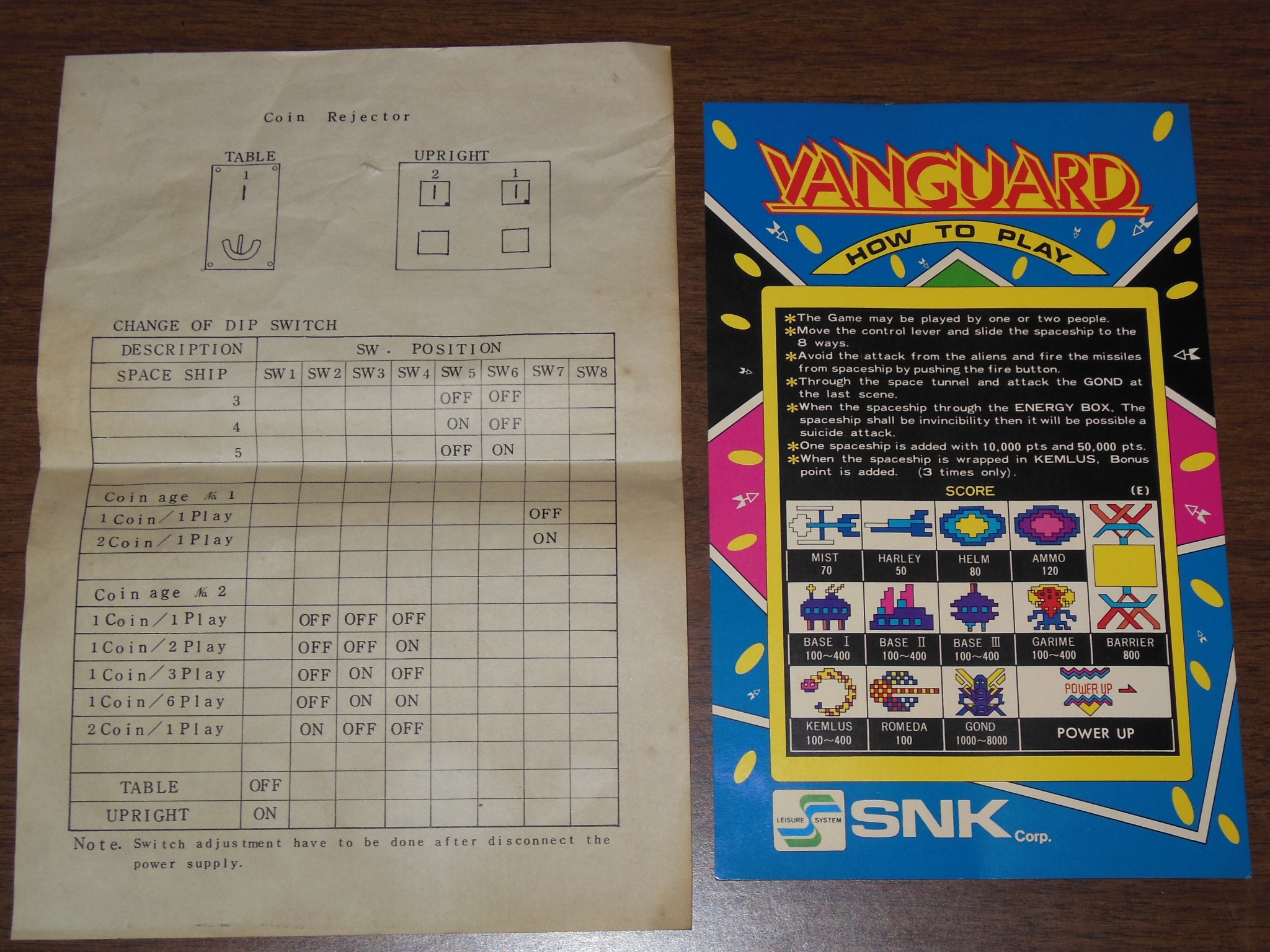
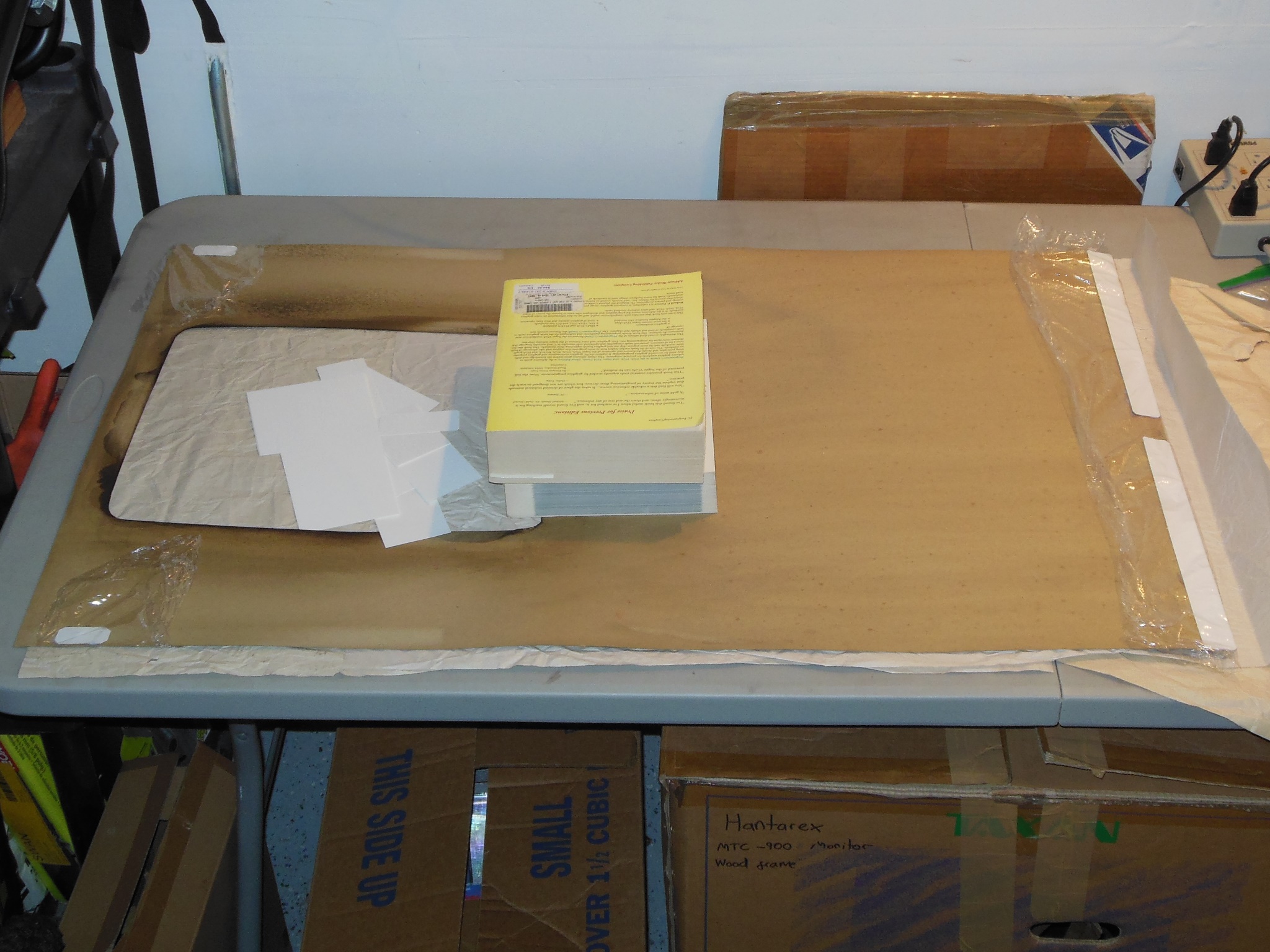
The game PCB and power supply components were removed in preparation for vacuuming the inside. In the base of the cabinet I found the game PCB DIP switch sheet and instruction card, presumably originally supplied with the machine.
|
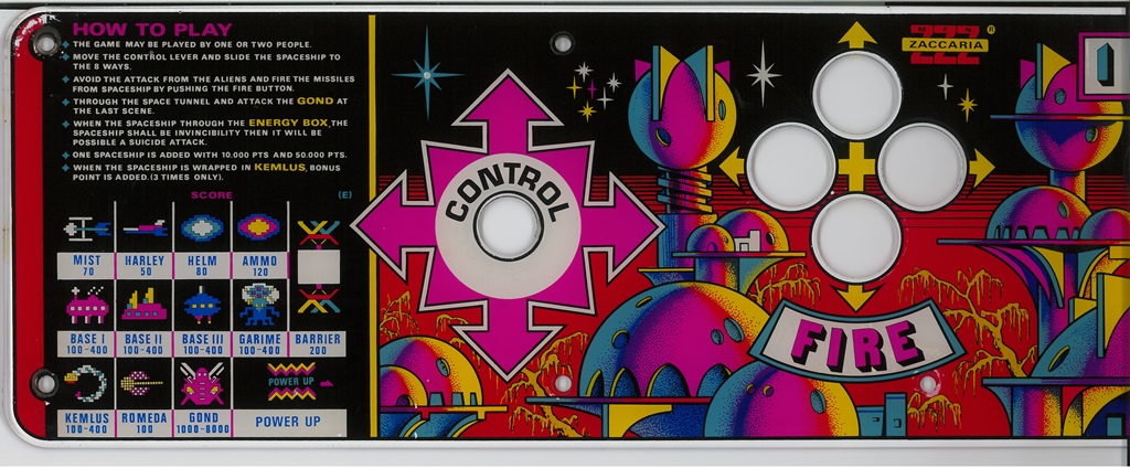
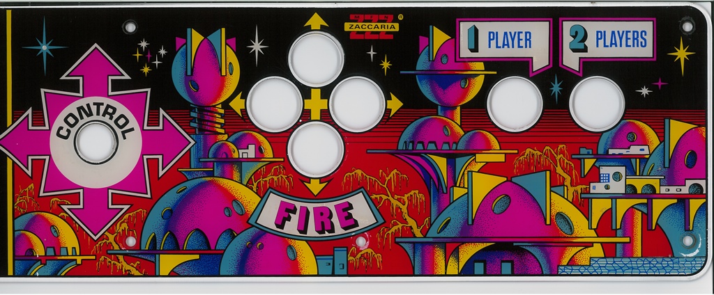
Scanned in the Vanguard control panel overlay.
400 DPI Vanguard control panel overlay scan (18.1MB).
|
|
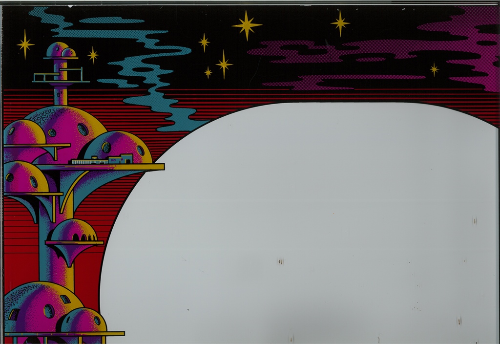
Scanned in the Vanguard monitor glass.
300 DPI Vanguard monitor glass scan (28.5MB).
|
All the buttons and joystick were in good condition, needing only cleaning. The complete cleaned control panel looked almost pristine.
|
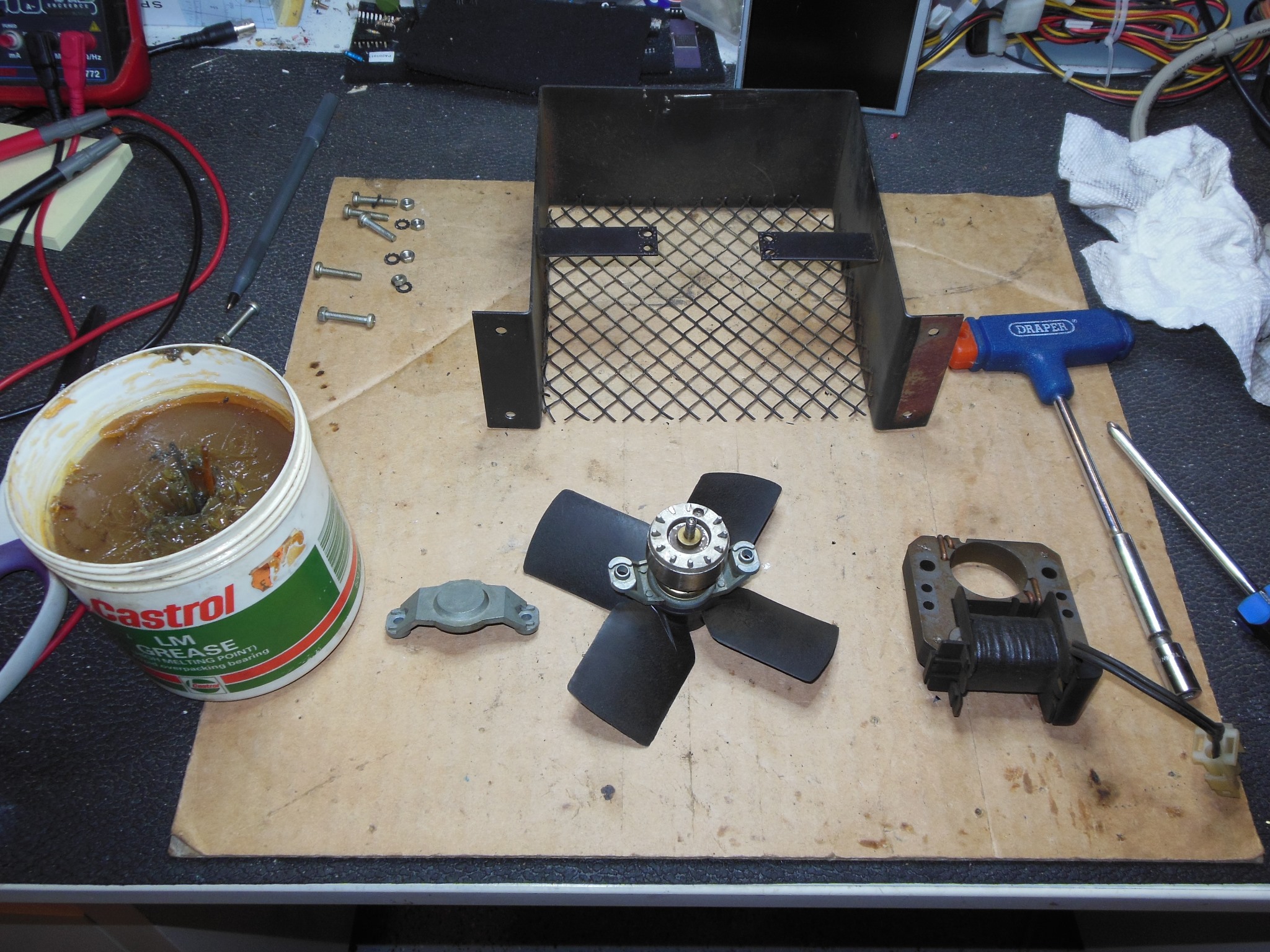
The power supply fan was disassembled, cleaned and the bearings greased. It was one of the best condition fans I'd seen - surface dirt but almost none of the rust usually prevalent on the grill.
|
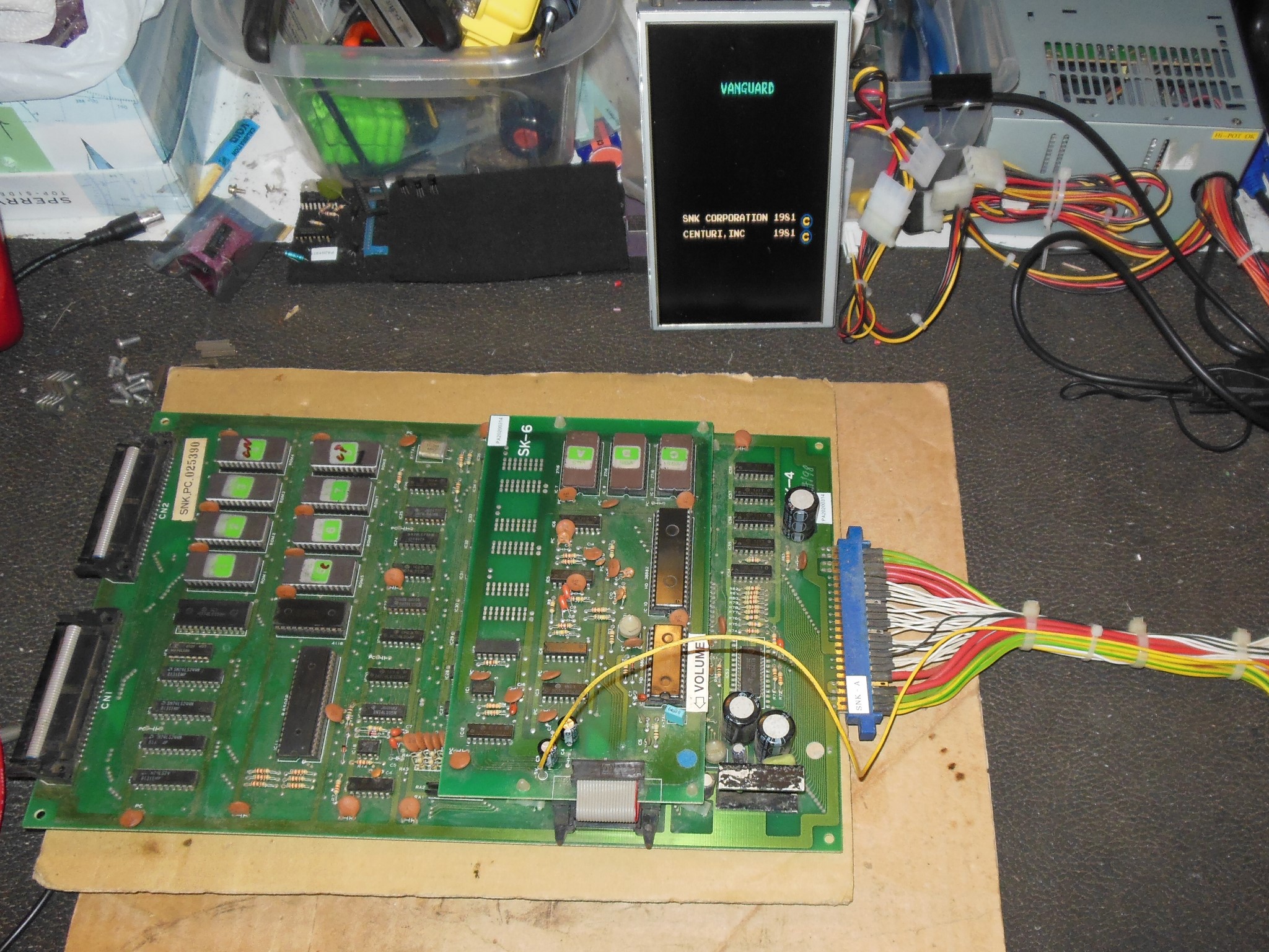
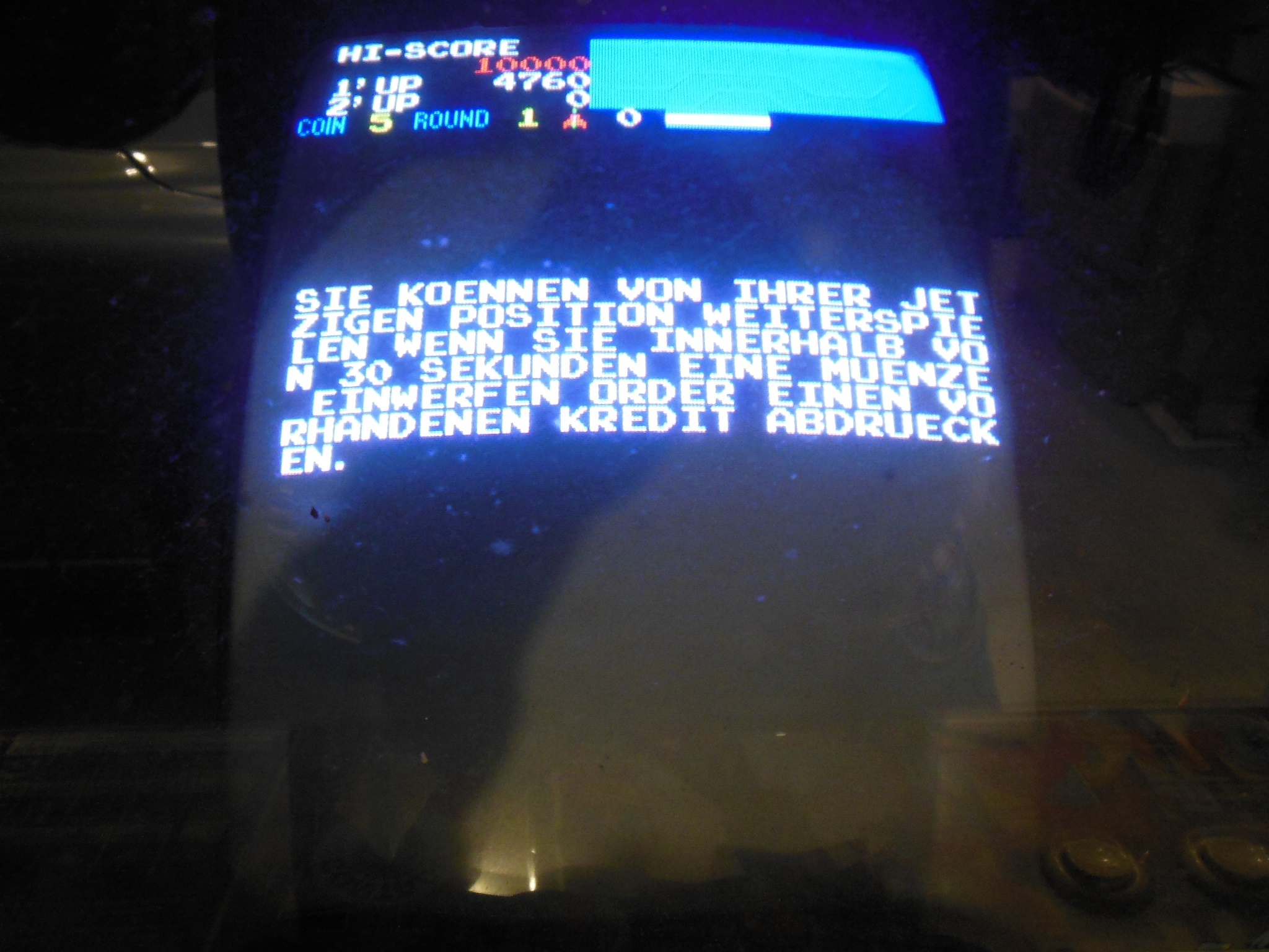
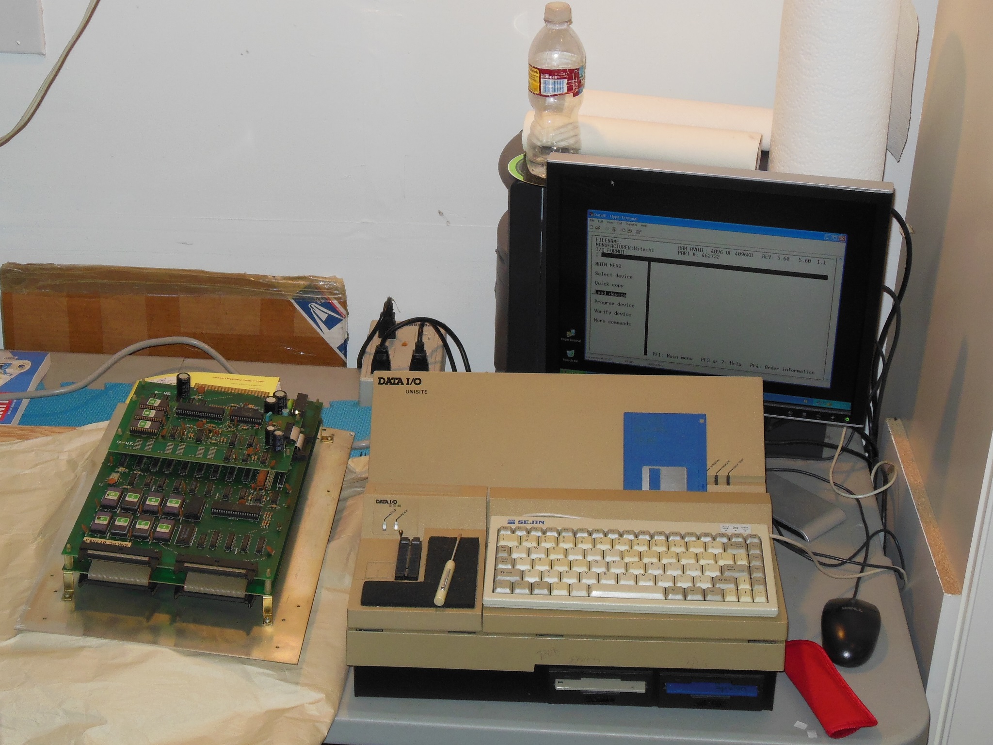
I'd noticed that the game continue text was in German and looking at the game PCB
there were EPROMS with hand-written letters over the factory labels. There was nothing
in the Vanguard MAME driver documenting a German version of Vanguard so I dumped the
ROMS for the archive.
SNK Vanguard (German) ROM set
|
Only minor repairs were needed on the monitor surround - a cracked crease along the top (causing sag) and a couple of patches for the side staples. The surround was set for the repairs to dry.
|
The surround was carefully fitted back into the cabinet and the monitor glass & control panel installed.

|
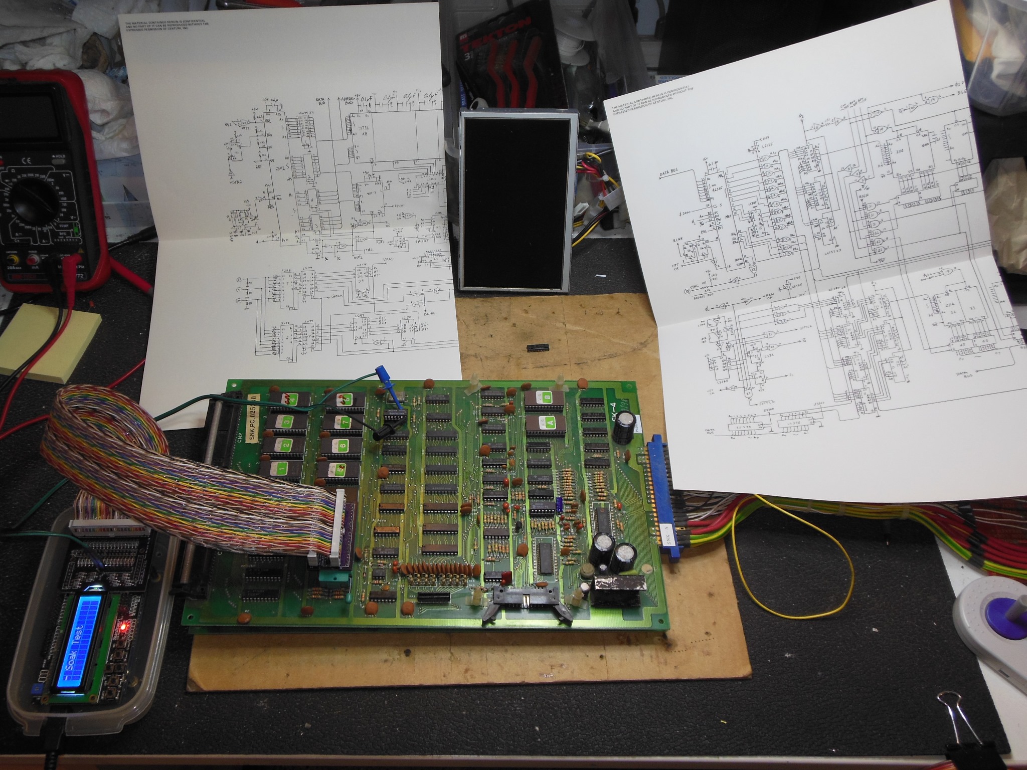
The best-of-the-bunch spare PCB was crashing during attract mode. Support for Vanguard was added to the Arduino ICT but ROM & RAM tests encountered no failures, including a 6 hour soak test. Trying a replacement 6502 CPU didn't fix the issue. It's pretty rare for the ICT to pass but the game to fail, usually indicative of bus level or timing sensitive fault. Alas, during testing on the bench the game no longer booted at all.
This time the ICT detected ROM check failure across all ROMS. A ROM Read operation on a selection of ROMS showed random data differences suggesting an address problem rather than a data bit problem. Checking with the scope found IC1 (LS244) input pin 11 "A0" high but output pin 9 low. A piggy back of IC1 still showed pin 11 at 0.4V with a high input. Something was pulling buffered A0 to ground. Isolating as much as possible by disconnecting the video PCB and removing all the socketed ROMs & RAM, the pull to ground still existed. There wasn't much left to choose from, IC1 itself or IC34 (LS155) input pin 13. A stiff pullup on buffered A0 still wasn't enough garner a high so the next plan was a dead short to +5V in the hope that something physical happened. I wasn't disappointed, a dead short to +5V instantly began burning up IC1. Replacing IC1 (LS244) fixed A0 and the ICT was all passing again. I'd hoped that this was also a possible cause for the crashing but alas the game was back to booting but crashing in attract mode :|
Theorizing that maybe IC12 (4118) RAM was suspect, I replaced it with a 6116-3 and the crashing got much worse, the game not making it past title screen. That hinted the issue was somewhere close. Going back to the ICT and running a ROM CRC check whilst poking around with the scope found IC12 pin 17 "D7" with very soft edges compared to D0-D6. Since the ICT is idle when not running a test I was also able to see that D0-D6 were floating but D7 was high, 2mV to 3mV lower than +5V, when the bus was idle. It looked like something was loading D7 to +5V, but only enough to cause an intermittent issue.
Following the same strategy as was used to hunt the pulled A0, the video board was disconnected and all the socketed ROM & RAM removed. However I wasn't so lucky this time because the data bus still connected to 8 IC's :(
Since I'd just replaced a faulty LS244 and D7 originated at an identical device I
cut the D7 output pin on that device. The pull was still present, however.
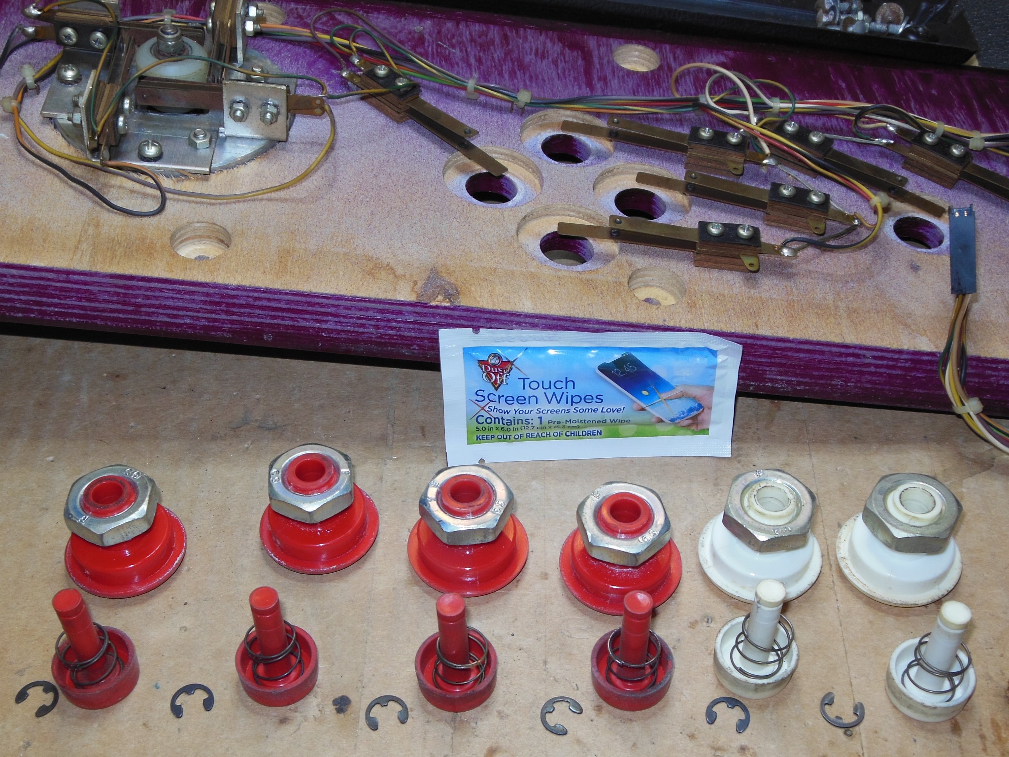
With the ICT idle and a multimeter setup to measure the D7 voltage against +5V,
I did a pass through all the remaining D7 connected devices with freezer spray
in the hope of detecting one impacting the pull:

|
The final step of the restoration was fitting castors to the base.

|

|
|
After a final cleaning, a burn-in test for 12 hours encountered no issues. The restoration was complete.