
|
|
This game had been working reliably for a few years since its initial restoration. Setup and show opening showed no issues aside from a low volume explosion sounds that I'd left as is.

|
By Sunday the game PCB had started to exhibit graphics problems with a sort of "window blinds" effect over the game graphics. A power cycle brought the graphics back again but only for a few minutes. The game was powered off for the remainder of the show.

|
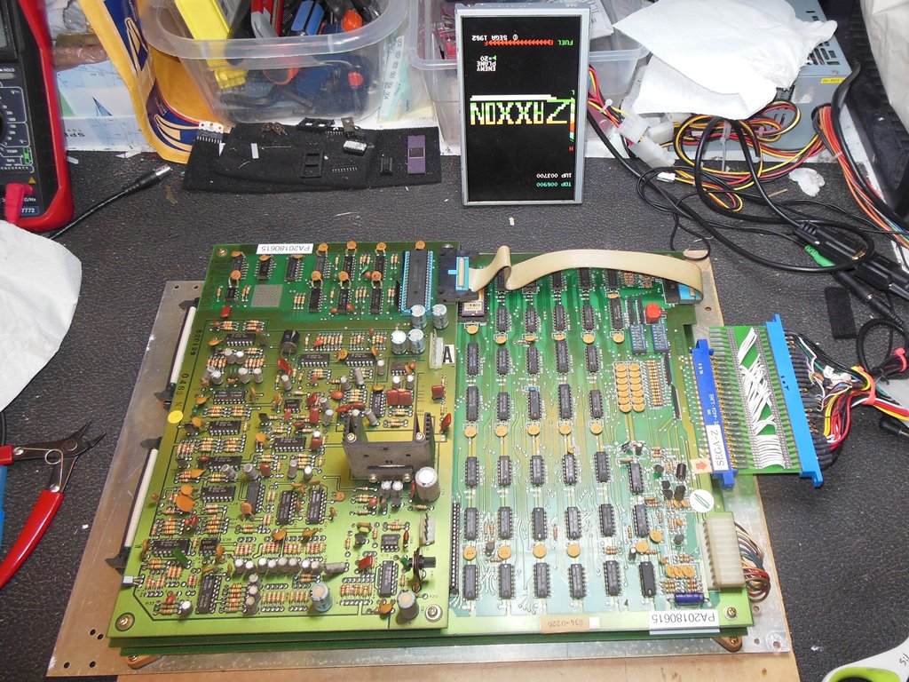
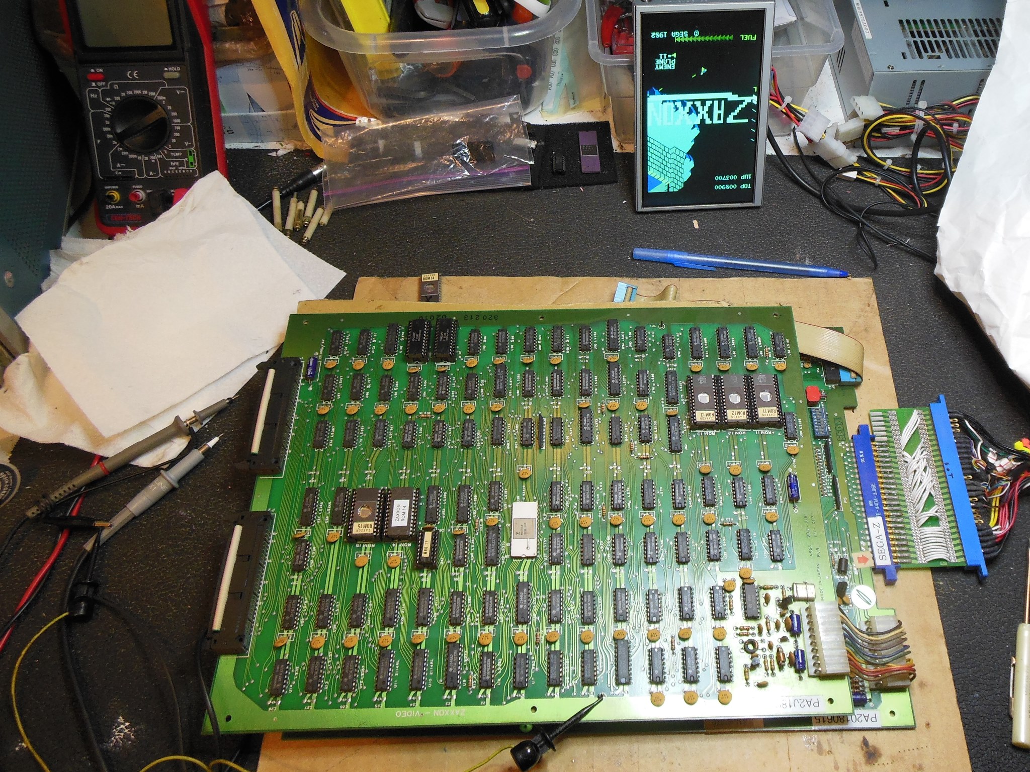
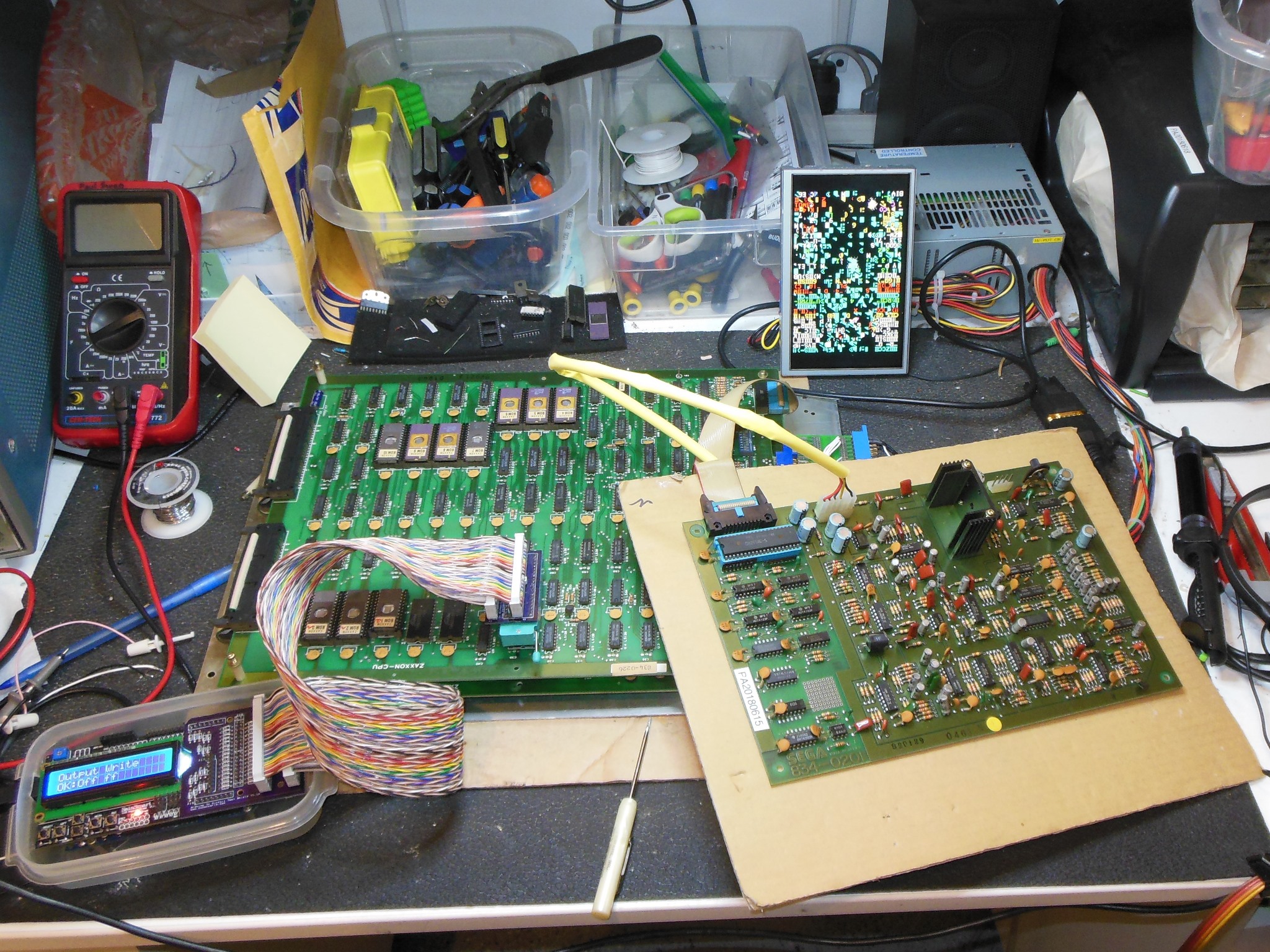
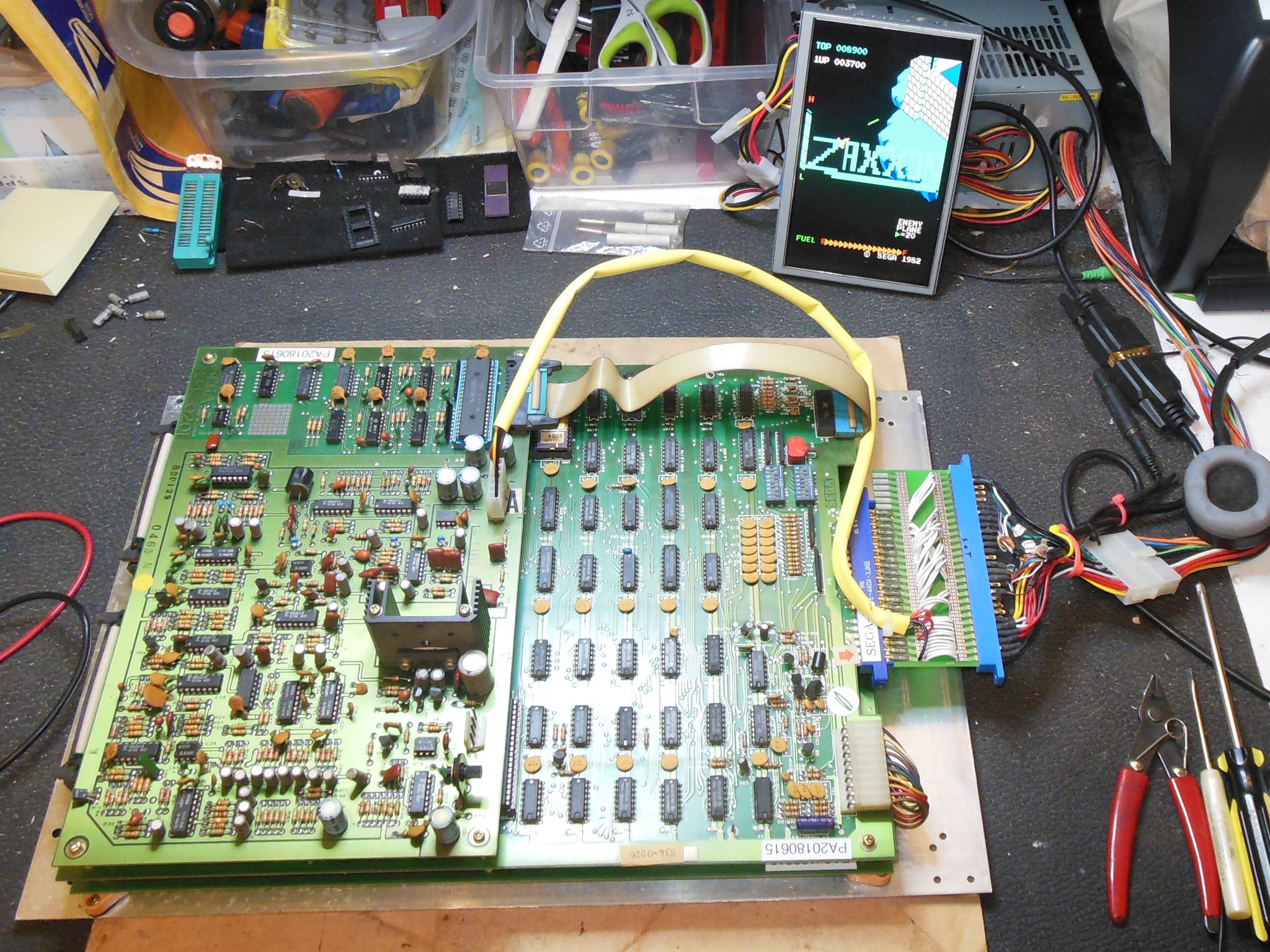
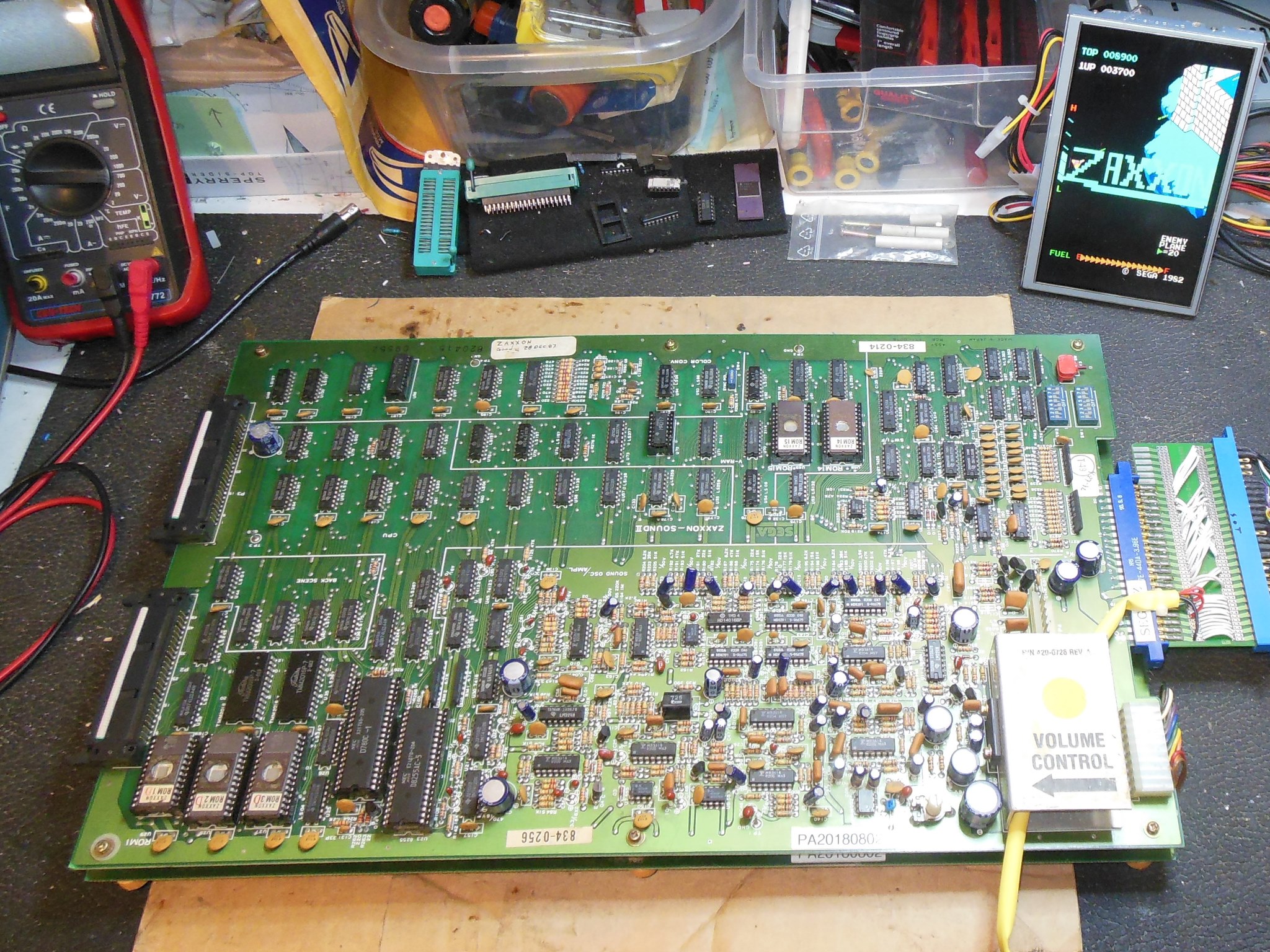
On the bench the game graphics were missing entirely leaving only off-coloured text visible on screen. The self-test passed all the ROM & RAM suggesting a display issue. Fault finding on this 3-board Zaxxon PCB set was complicated by the lack of matching schematics - all the manuals seem only to cover the large 2-board set version :( Background data was present on ROMs 7-10 data bus and ROMs 4-6 data bus. IC 41-43 (LS299) pins 4,5,6 & 7 inputs looked OK. Output pin 17 was active in game mode and a video probe showed the background scrolling in attract mode OK so it looked like IC 41-43 had no obvious issue.
Moving on to the video PCB, the background was present on IC 101 (93422 RAM) pin 12 (D out). IC 102 (S373) inputs & outputs looked OK also. Back on the CPU PCB, checking PROM IC 76 (28L22) found the inputs mostly blanked during video active time but active during blanking time. IC 99 (LS27) input pins 1, 2 & 13 (1VD0, 1VD1) were always following blanking. On the video PCB the 1VD signals were part of the text plane (nothing to do with the background) fed from the data of ROMs 14 & 15. Text data was present IC 52 (LS299) pin 17 but IC 53 (LS299) pin 17 was stuck active when the video was active. Checking ROM 14 (2716) found the data bus bad. Shorting pins 8 & 9 (A0 to D0) brought back snow of the missing background. Programming a new 2716 EPROM to replace ROM 14 brought back the background and fixed the off-colour text (since text is higher video priority than all other graphics the faulty text data was masking all other video).
|
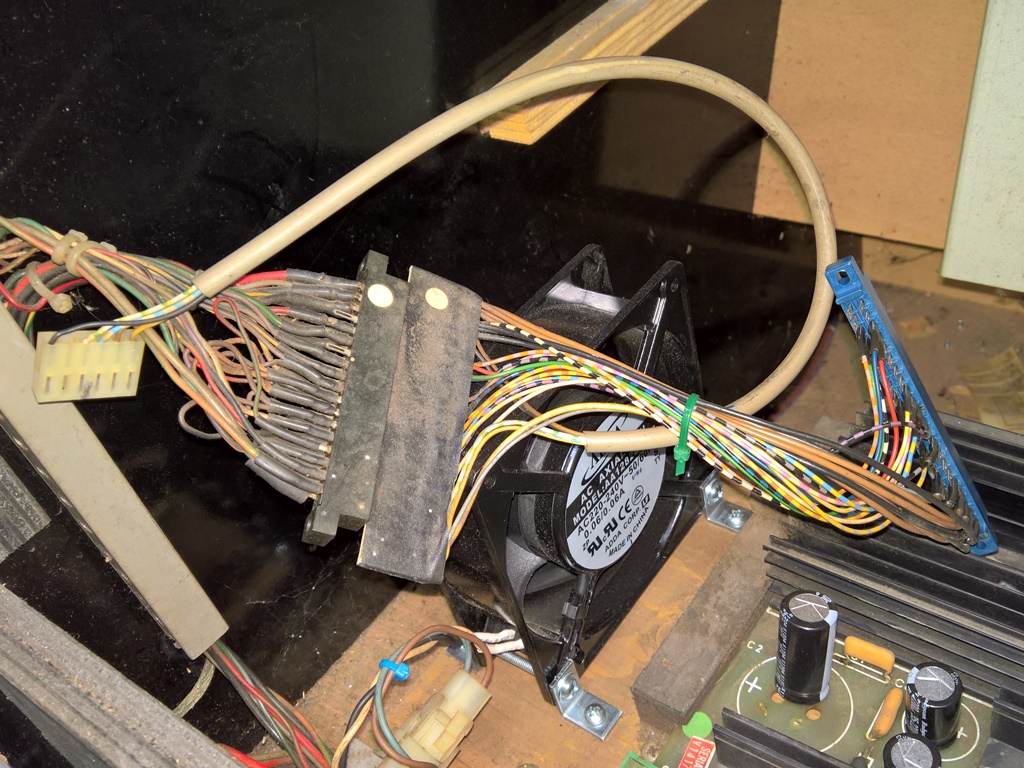
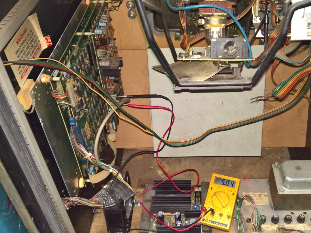
Since this cabinet was a distributor conversion from a Konami Tactician there was a wiring adaptor to convert from Konami to Sega Zaxxon. I'd previously noticed that the game took a few seconds to boot and that the +5V was around 4.65V on the game PCB itself in the cabinet. I'd not seen the game PCB take seconds to boot on the bench - it came up straight away.

|
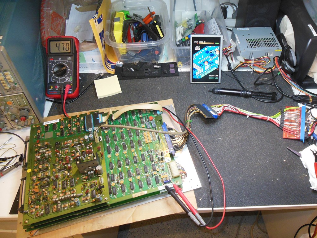
On the bench with the Konami-to-Sega wiring adaptor in the chain the +5V measured +4.71V at the game PCB. The full voltage profile was:

|
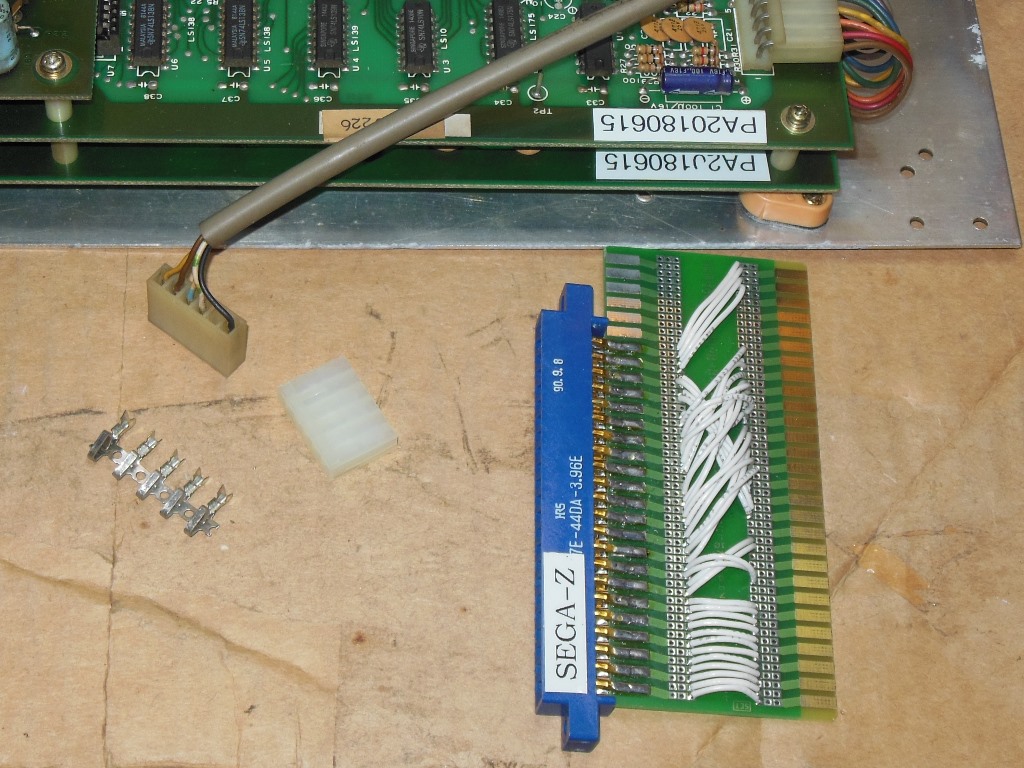
In order to use my own JAMMA-to-Sega adaptor I needed to add the external sound plug that was required by the 3-board set. Since I'd not found any information on the 3-board set in any of the Sega manuals I needed to determine the pinout of the sound board connector with a multimeter, that is:-
|
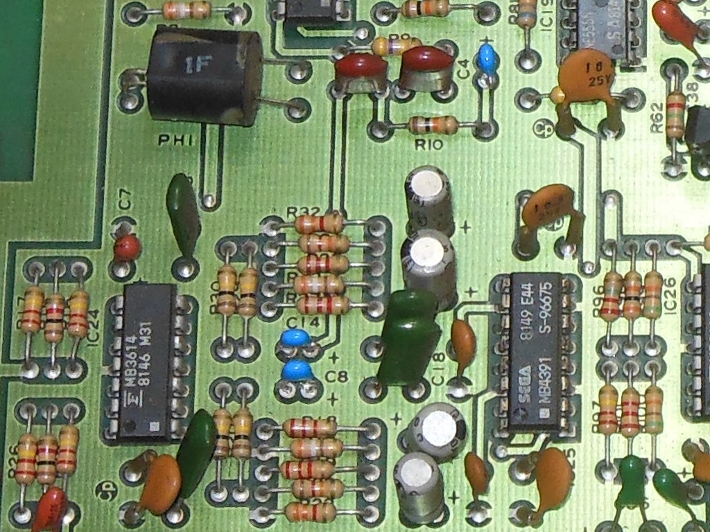
Since the board was on the bench I decided to investigate the poor explosion sounds. Though Zaxxon has a set of built in test menus getting to the sound test menu required skipping through other test menus first, including having to set the DIP switches, so I decided to add the game to the Arduino ICT and use that to more easily test the sounds.
Testing the sounds found that the ship sounds 'C' and 'D' were missing along with
the 'SM' and 'MD' explosions being poor. Starting with the ship sounds, 'A' & 'B' volume
controls were OK at PC1 (MCD-725H). IC 31 (7417) outputs 'C0' & 'D1' were also OK.
IC 24 (MB3614) pin 10 input 'C0' was OK but output pins 9 & 10 were idle. The
routing of these signals on this 2-board set sound PCB is...
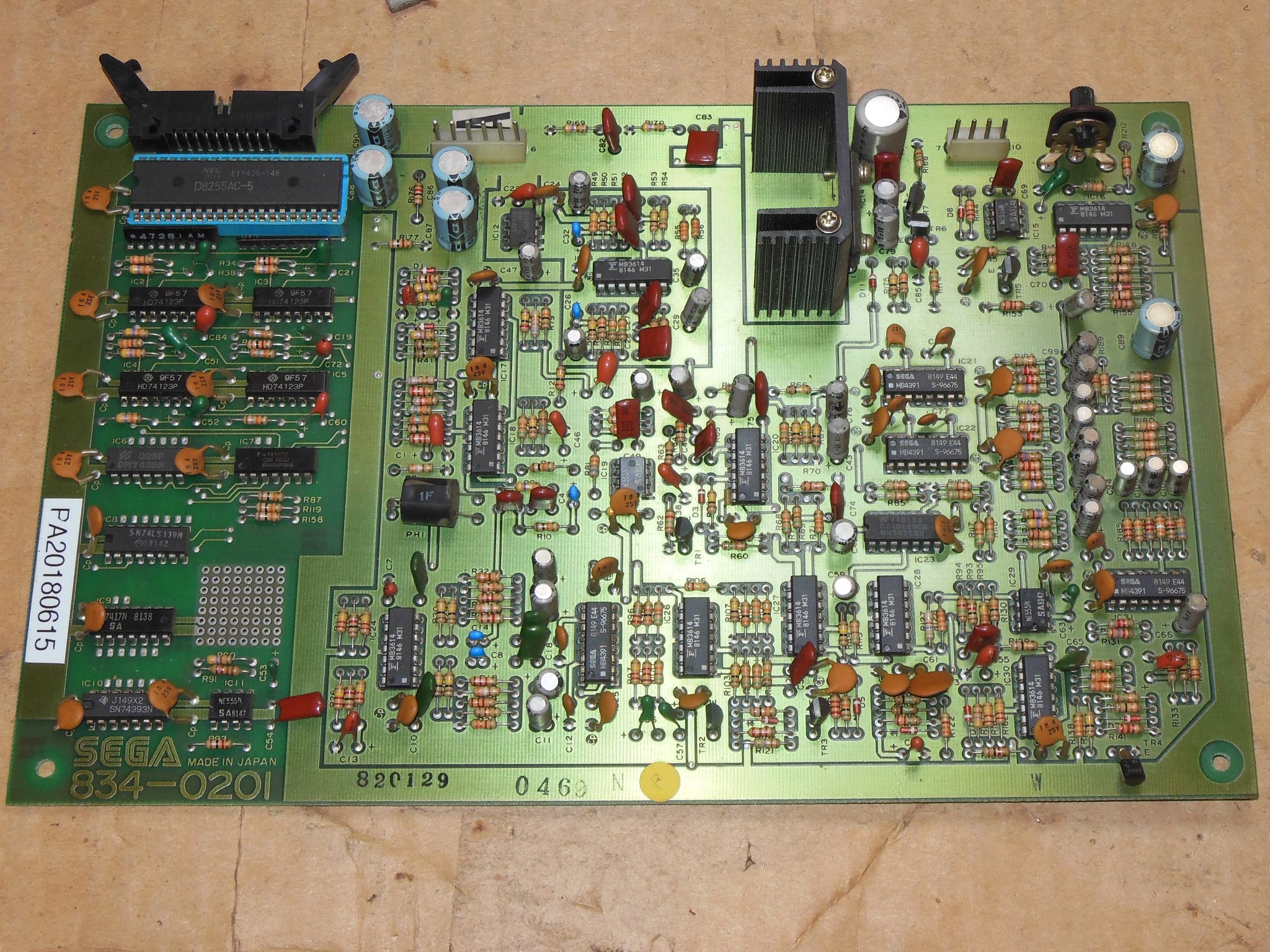
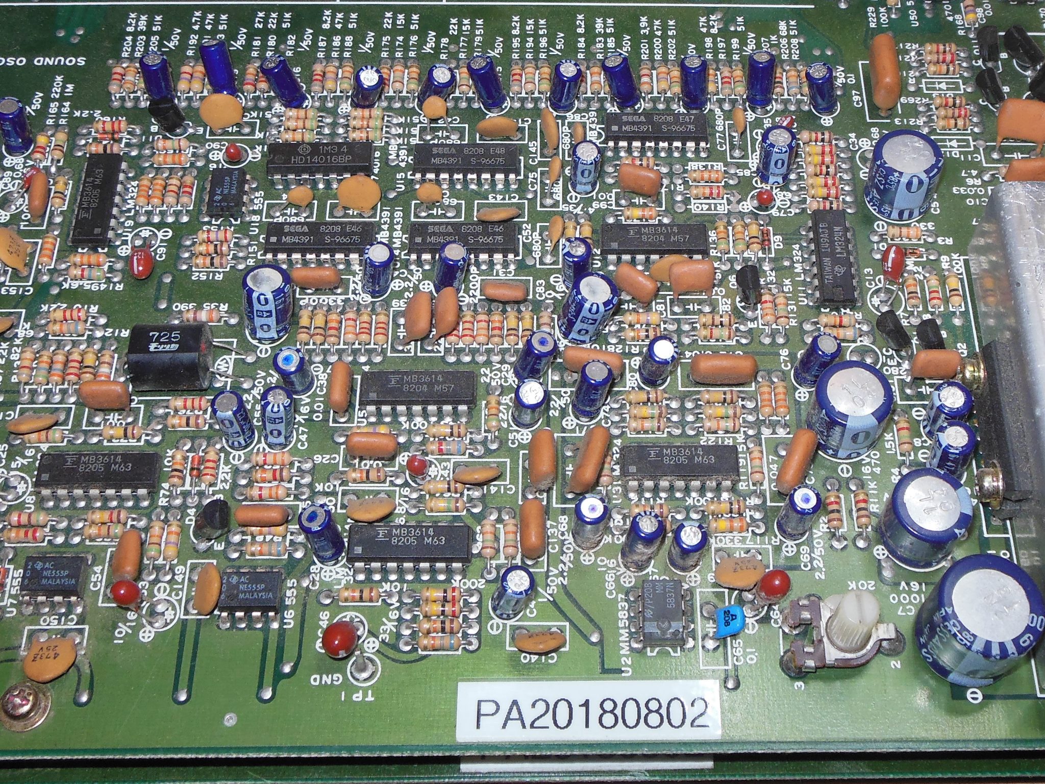
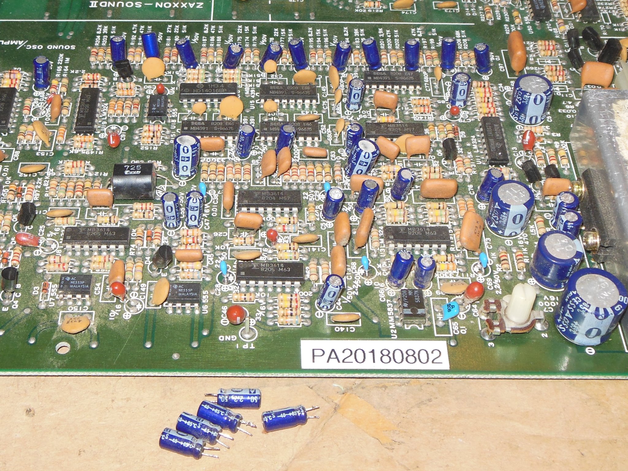
Moving on to the explosions, the triggers were present for 'SM' on IC3 (74123) pin 9 and 'MD' on IC3 pin 1. IC 17 (MB3614) pin 1 appeared to be the 'noise 2' source and IC 12 (MM5837) pin 3 showed 12V p-p noise output. IC 21 (MB4391) pin 6 'MD' explosion control appeared to be working OK. Probing IC 13 (MB3614) pin 10 with the scope initial read at +12V but then dropped down. At the same time, the explosion sound started working properly. The same effect occurred at IC 13 pin 5 for the 'SM' explosion, where the scope lead cause the signal to drop down from +12V and the explosion to start working properly. I suspected bad sound caps that I'd heard rumors of being a problem on this game.
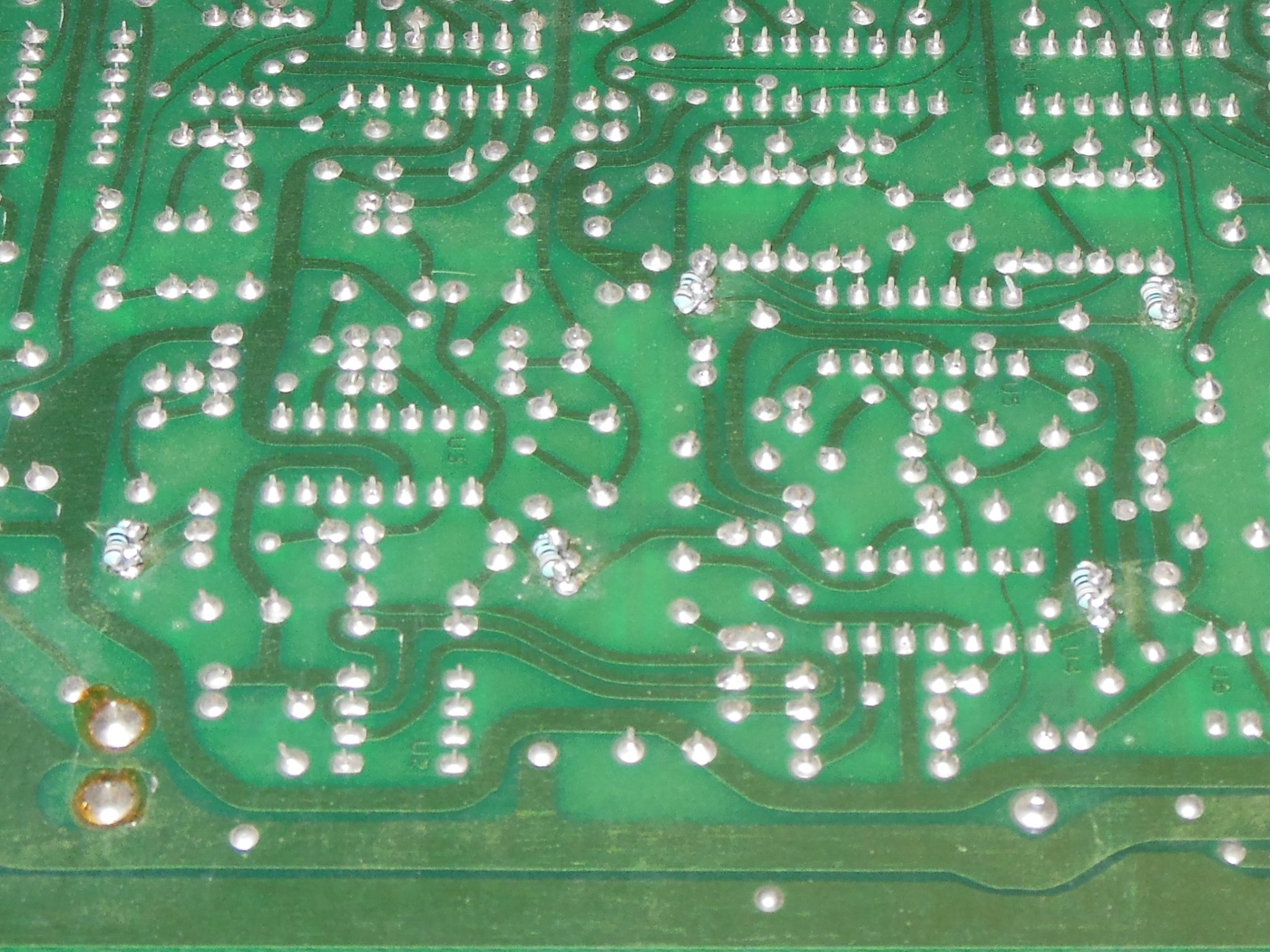
A web search found the exact description of the problem I was seeing with the explosions, the root cause of which was a design error in the sound circuit that had omitted a DC bias path from some of the op-amp inputs. Without a DC bias path, the DC voltage on the inputs floated around at the mercy of capacitor & op-amp leakage. Two fixes were suggested - either use low quality replacement capacitors that had a lot of leakage or use a none-polar capacitor and add a DC bias resistor. I decided to go with the latter option based on a 100K resistor bridged across the input capacitor to provide the DC bias, simulating the original capacitor leakage that allowed the circuit to work in the first place.

|
The replacement parts were:-
|

|
The capacitor pins needed to be reformed to reduce the pitch to match the original capacitor pitch but Digi-Key do carry the same capacitor in a narrower pitch that may be a closer fit. To assemble the capacitor was fitted first and then the resistor wound around the tails on the solder side, soldered and then the excess pin trimmed. The result was reasonably tidy despite the narrow pitch for the resistor to fit across.
|
With the sound caps and IC 24 replaced the Arduino ICT sound testing found all the sounds working reliably. I'd never notice that the ship "jet" sound was missing (and no one had ever mentioned it at the show) and the effect of low & high pitch matching the height of the ship is a nice detail :)
|
Over the years I'd acquired a few spare Zaxxon board sets before I discovered that the cabinet used the 3-board set and thus I had no spare 3-board sets (the 3-board set seemed to be much rarer that the 2-board set). Of the spare 2-board sets in various conditions there was one already fully working one in good condition to use as a temporary spare for the cabinet.
|
The explosion sounds were mostly working but as a preventative measure I replaced the five common problem capacitors with 2.2uF non-polar and 100K bypass resistors as noted previously.
|
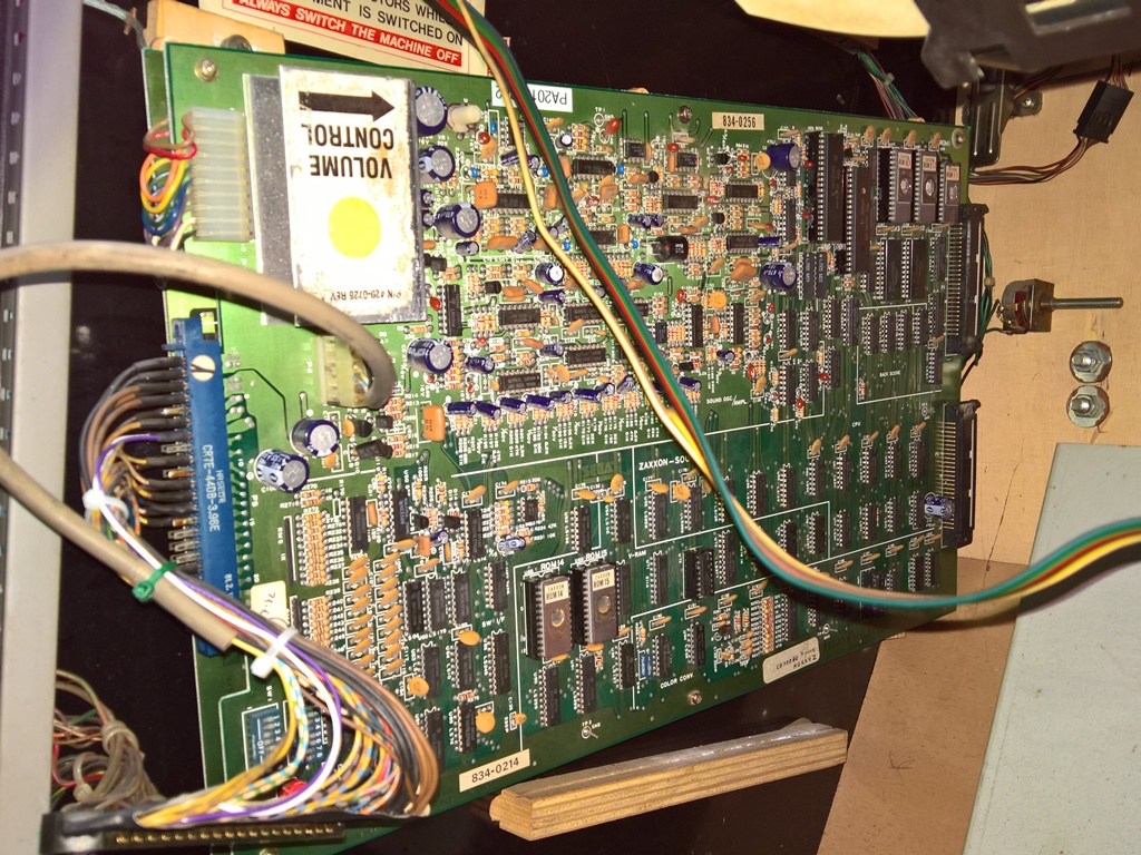
In the cabinet the large 2-board version was much larger than the Zaccaria mounting guides. I didn't need a permanent mounting for this spare board and with the bottom back foot slotted in behind the back guide the top front foot was able to line up with the pad used for the mounting plate screw (shown in the photo hooked onto the ground braid). Good enough for a temporary fix if the main board dies.
|
The +5V power supply was adjusted up from +4.79V to +5.05V that also had the side effect of making the picture brighter. After installing the original 3-board set the game still took a few seconds to clear reset compared with the 2-board set. Since it had always behaved this way and it didn't behave this on the bench I decided to leave as is. Play testing didn't turn up any further issues and the game ran fine for a few hours.