|
|
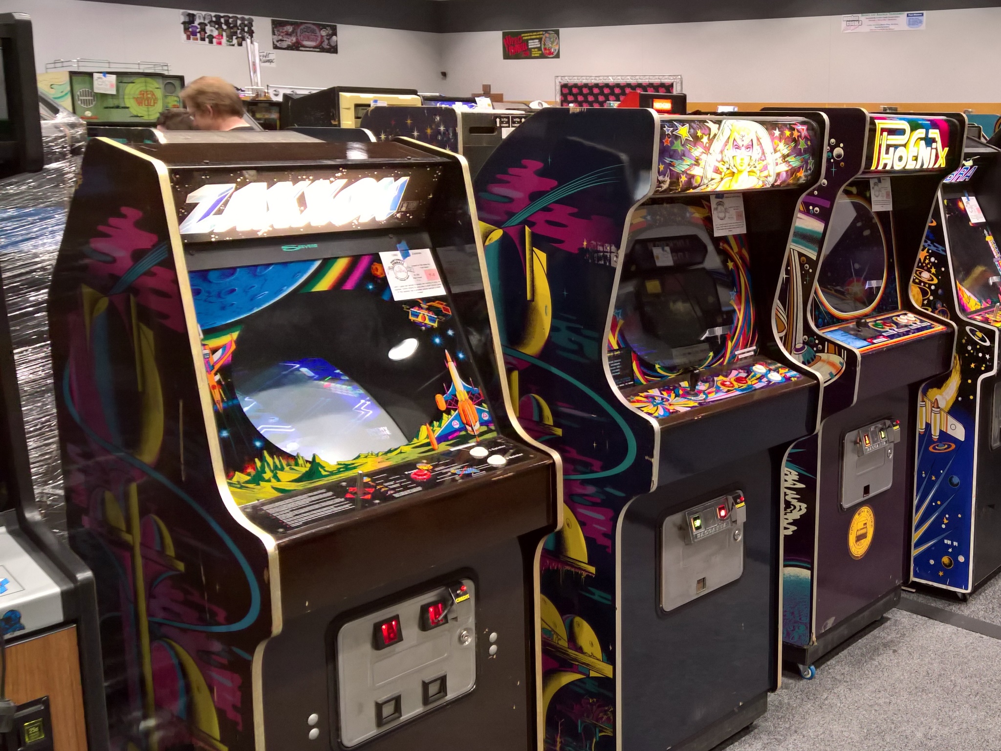
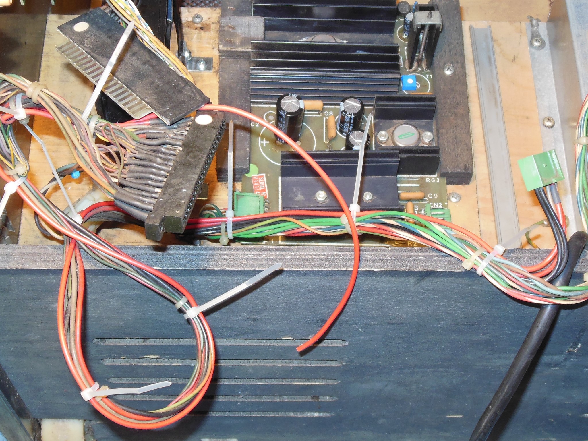
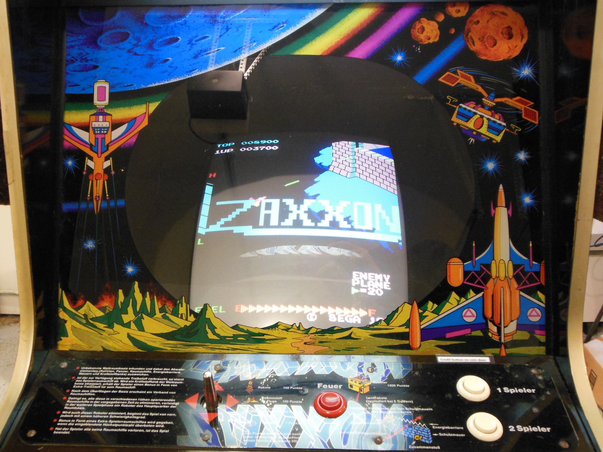
The game was running OK for the first few days of the show but by Sunday it was no longer booting with no video sync. Initial triage found the +5V output from the power regulator PCB at 3.36V and the AC power connector into the power brick had charred pins. The game was withdrawn into the dead zone for the remainder of the show :(
|
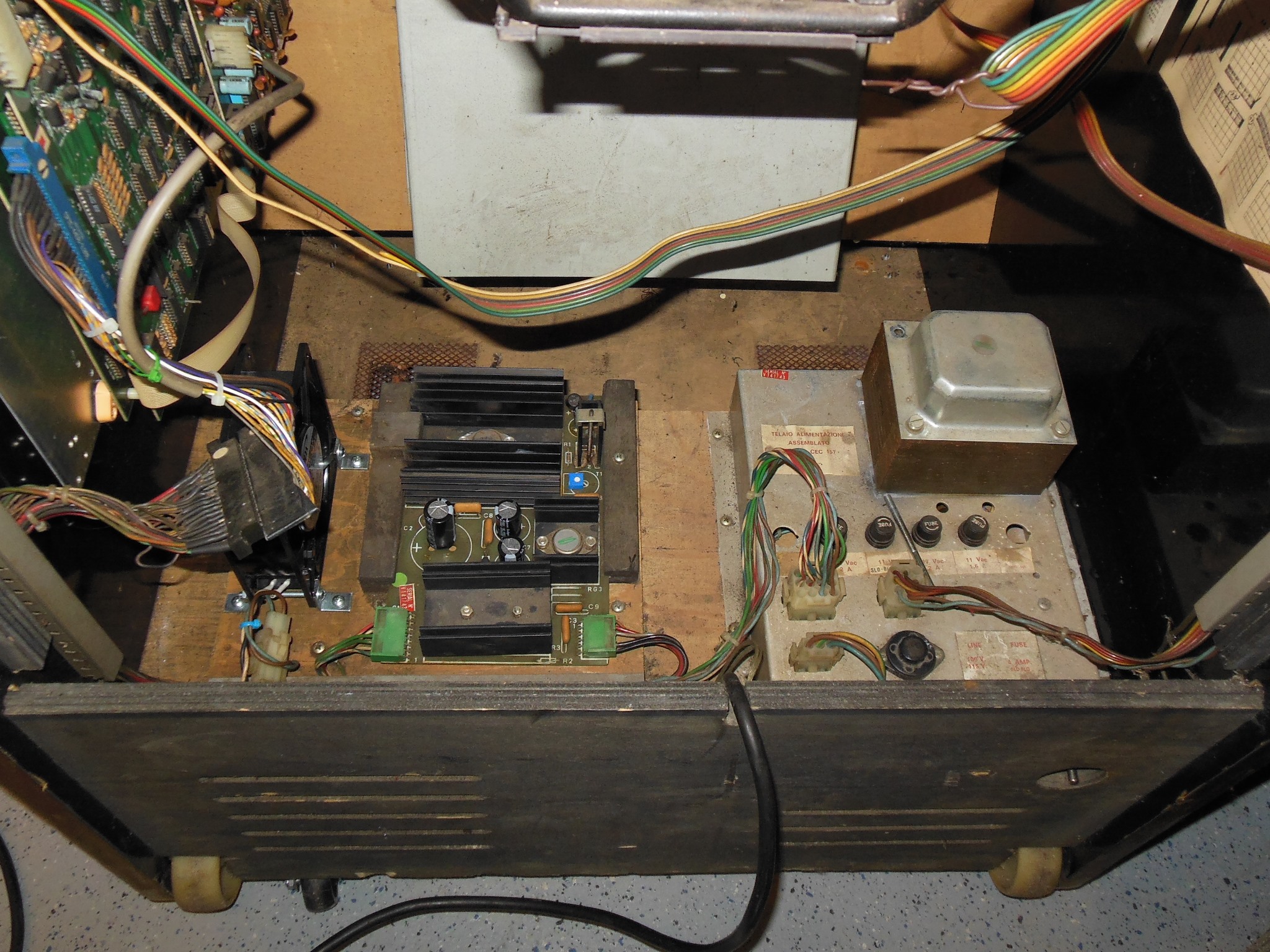
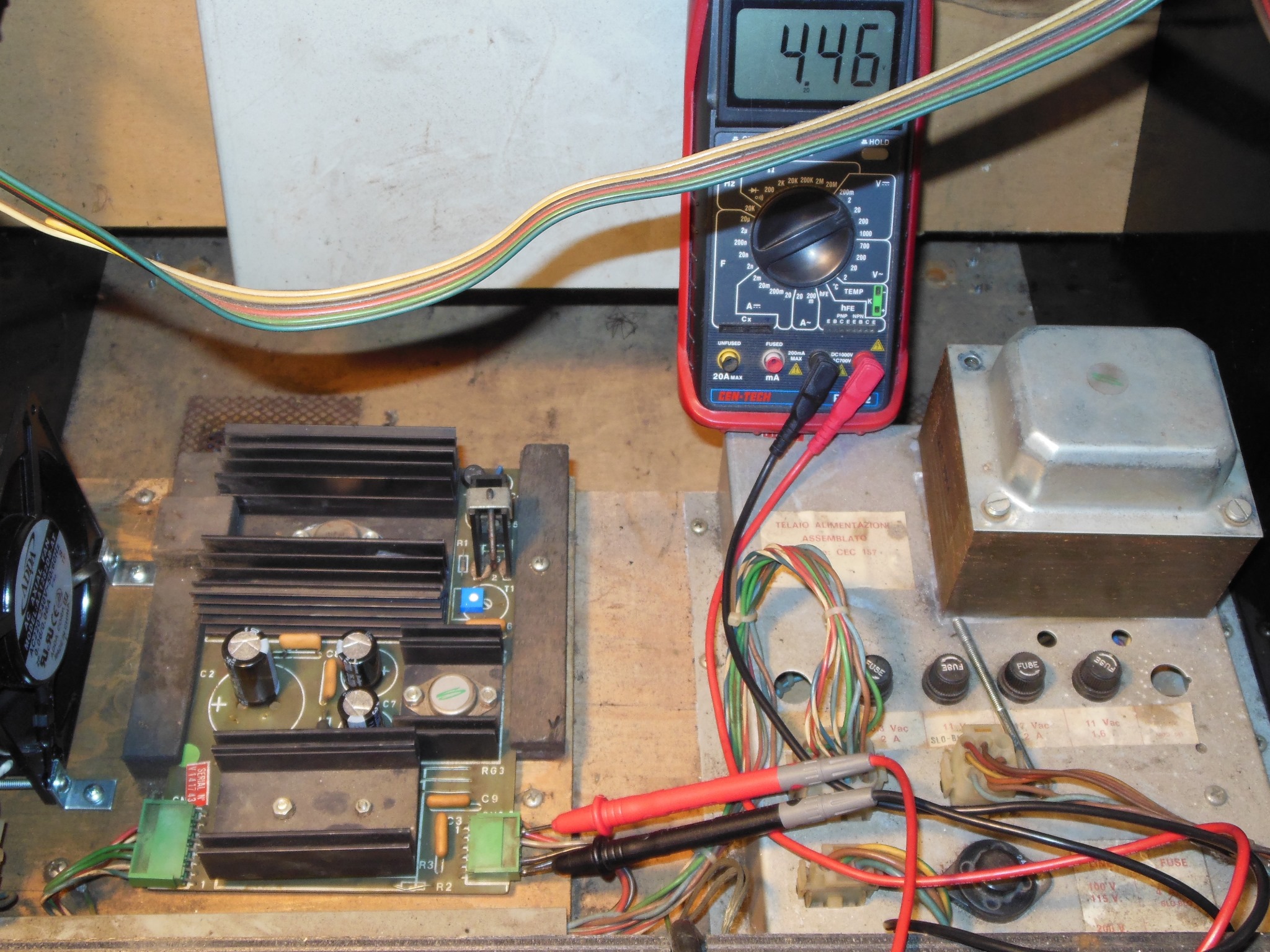
The +5V at the regulator PCB output measured 4.46V and I'd already noticed the charred power brick plug at the show. Other symptoms of power issues were that the regulator PCB connectors were already hot after a few minutes and the transformer was rattling so much it had shaken loose all its mounting bolts and was "sanding" the top of the frame (!)

|
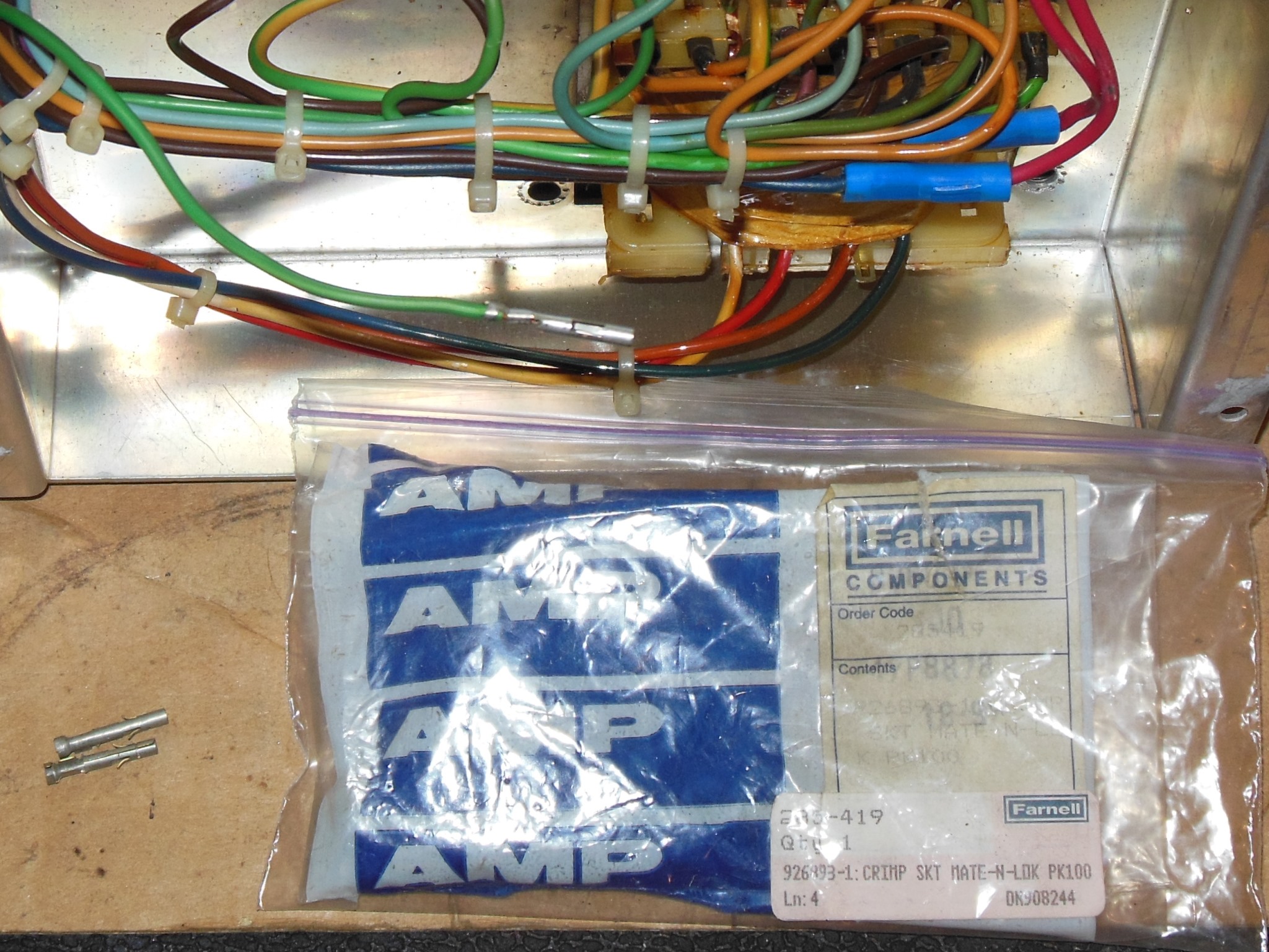
Replacing the female pin in the power brick was straight forward. A jewelers screw driver was used to push in the springs so the pin could be pulled out, cut off and a new pin fitted.

|
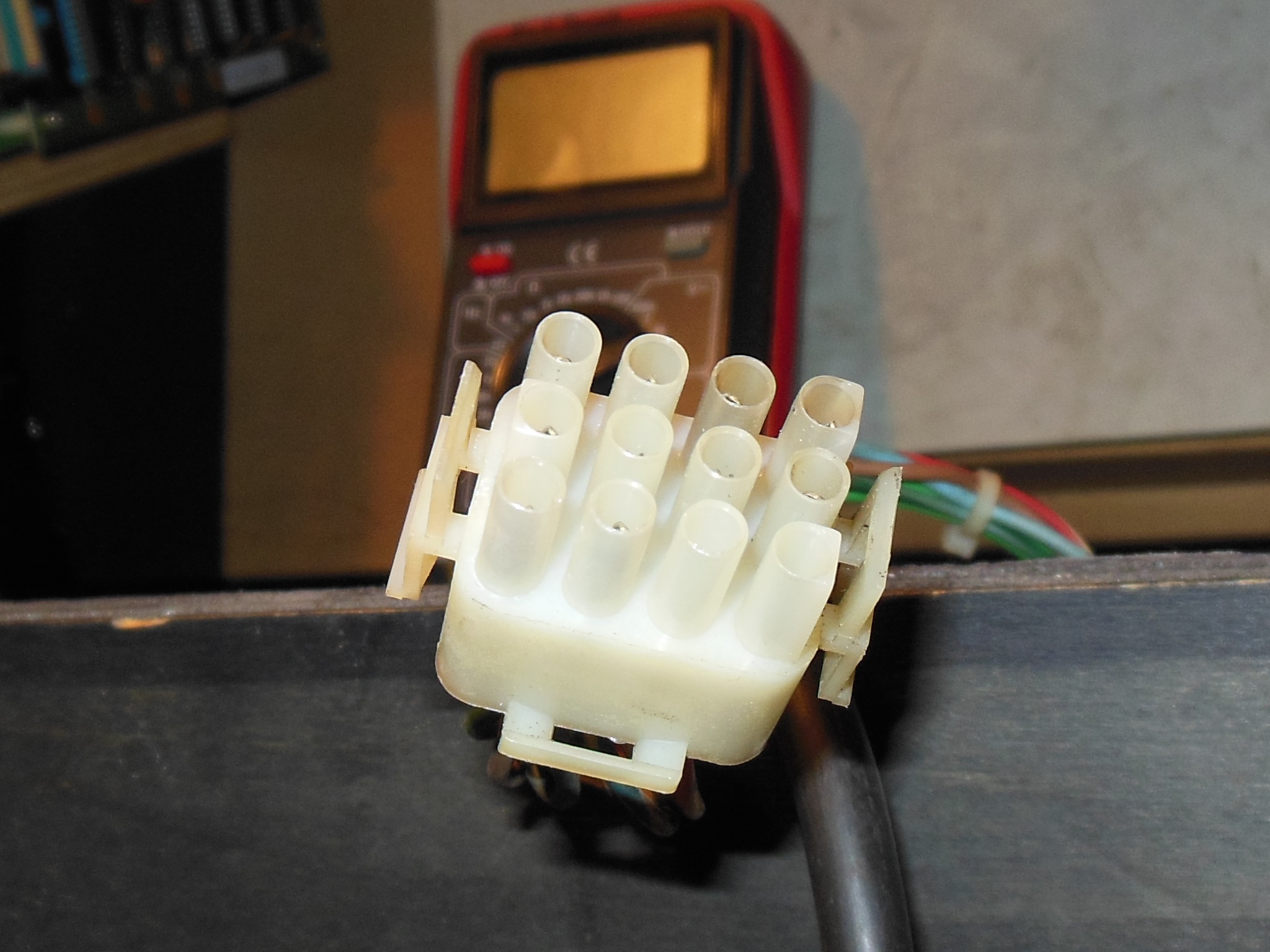
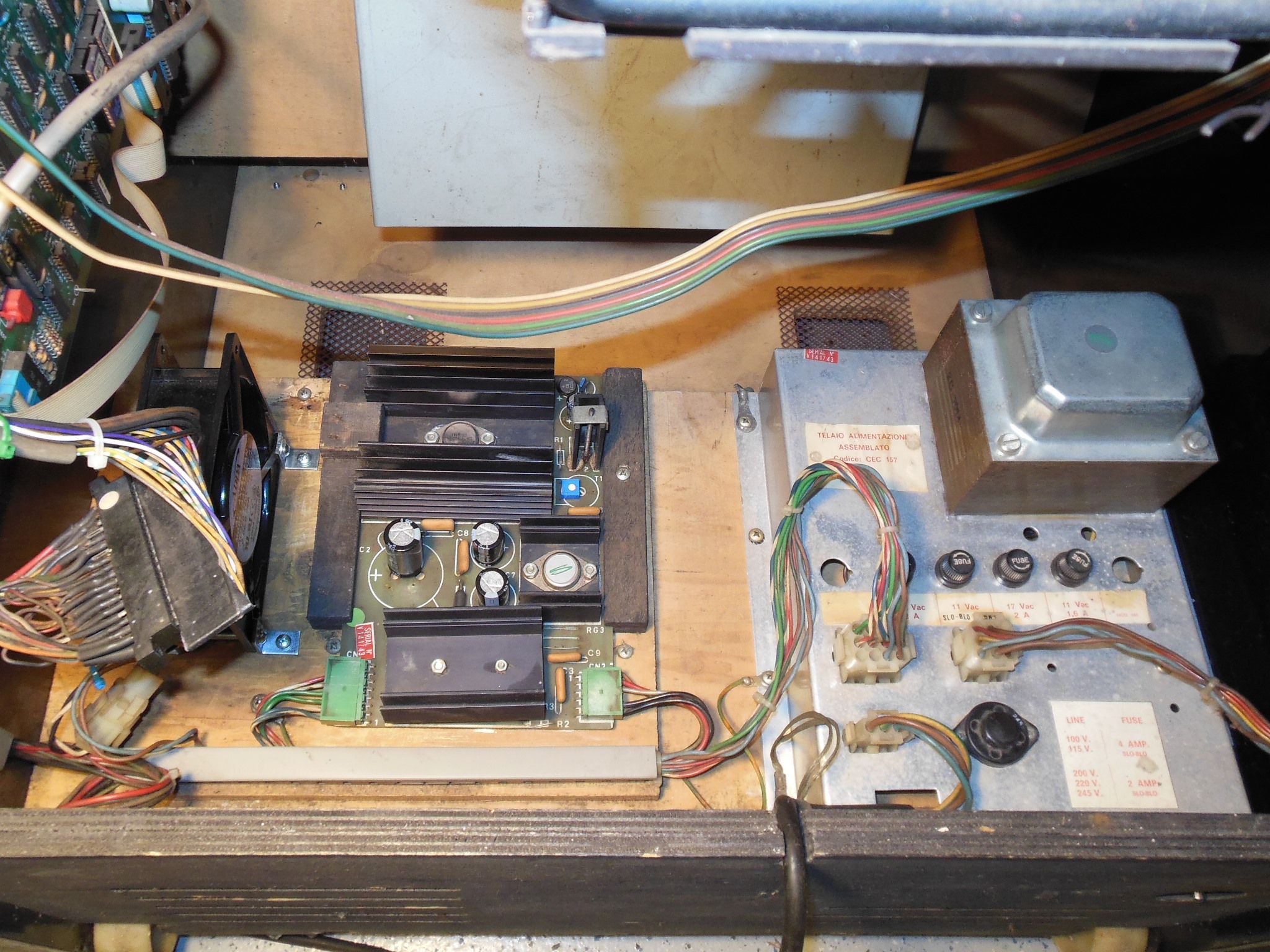
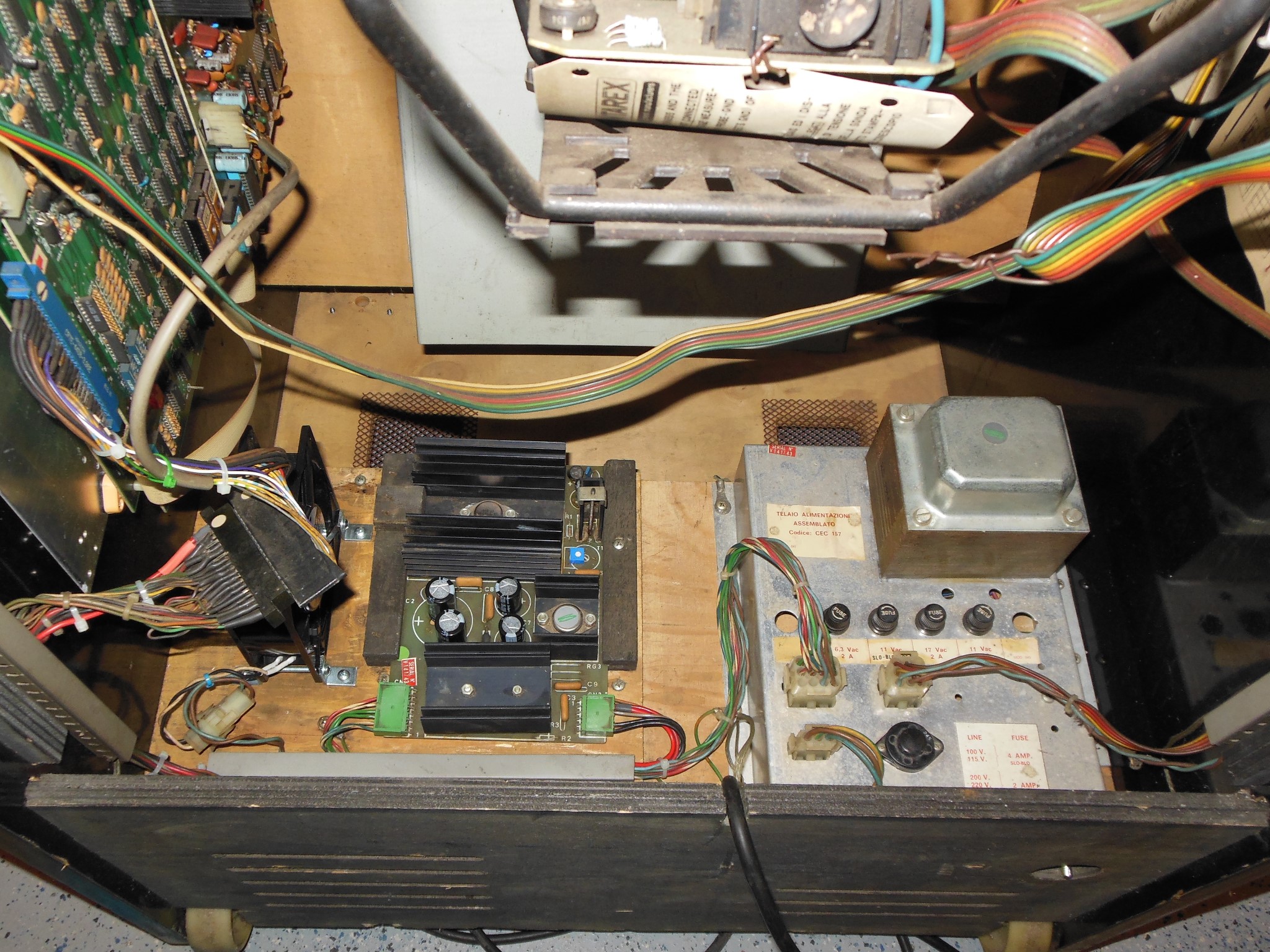
Cleaning the top of the power brick revealed the root cause of all the power problems on this game - the Zaxxon game PCB draws more +5V current than the cabinet power supply was designed for. The manual shows the linear regulator rated at 4A and the connectors, cabling & fuse rated at 5A. In this cabinet the distributor had replaced the 11V AC 5A fuse with 6.25A according to the neat label on the brick. Increasing the fuse value and a nice label doesn't change the design of the power supply :|


|
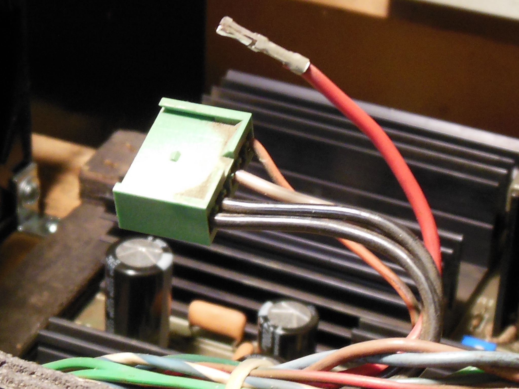
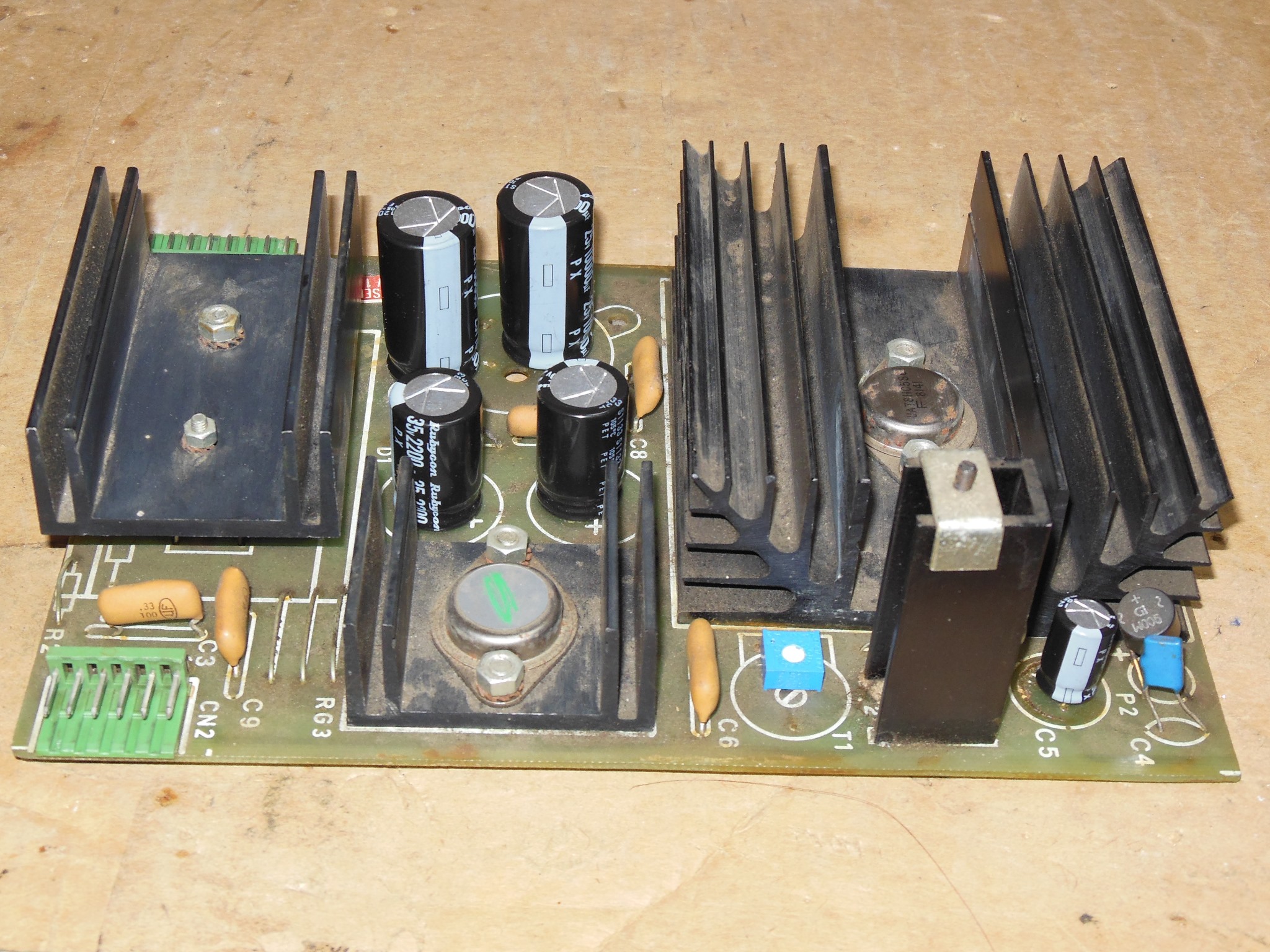
The replacement of the power brick and regulator connector pins followed the same procedure - a jewelers screw driver to depress the pin spring and release the pin from the housing, cut and replace with a new pin. The regulation PCB pins are straight forward to clean with a wire brush at the expense of snapping off the top cover to get at them.
|
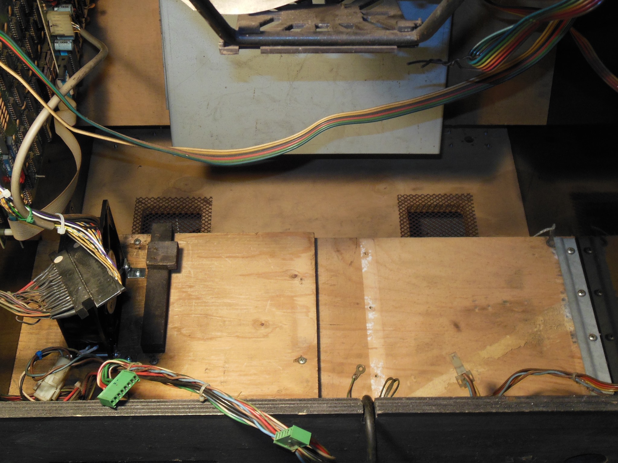
Whilst most of the power assembly was out of the cabinet I took the opportunity to vacuum & clean the cabinet bottom.

|
After all the AC side power repairs the game PCB still wasn't booting in the
cabinet but ran without issue on the bench. Checking the power voltage along
the chain:
|
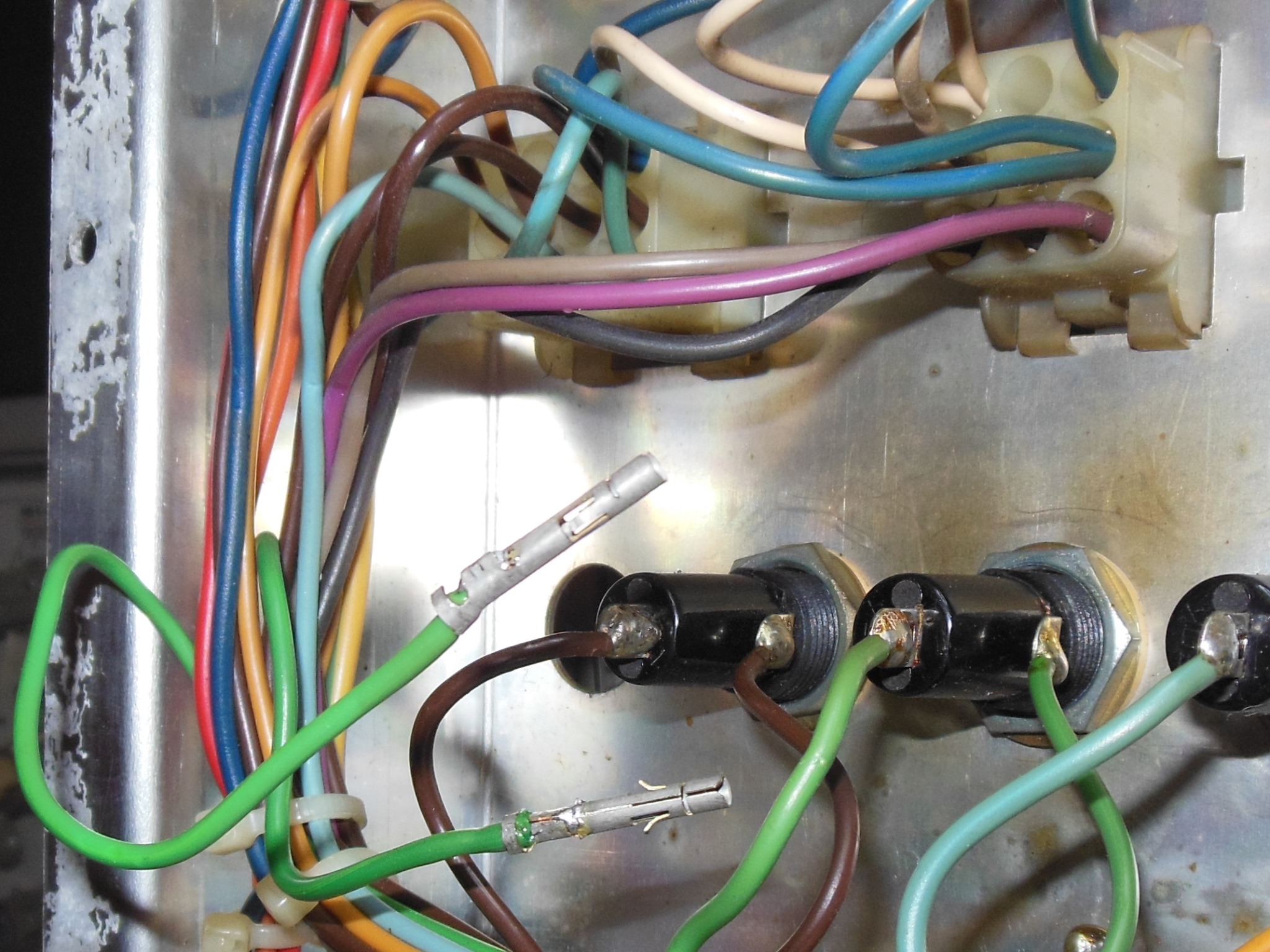
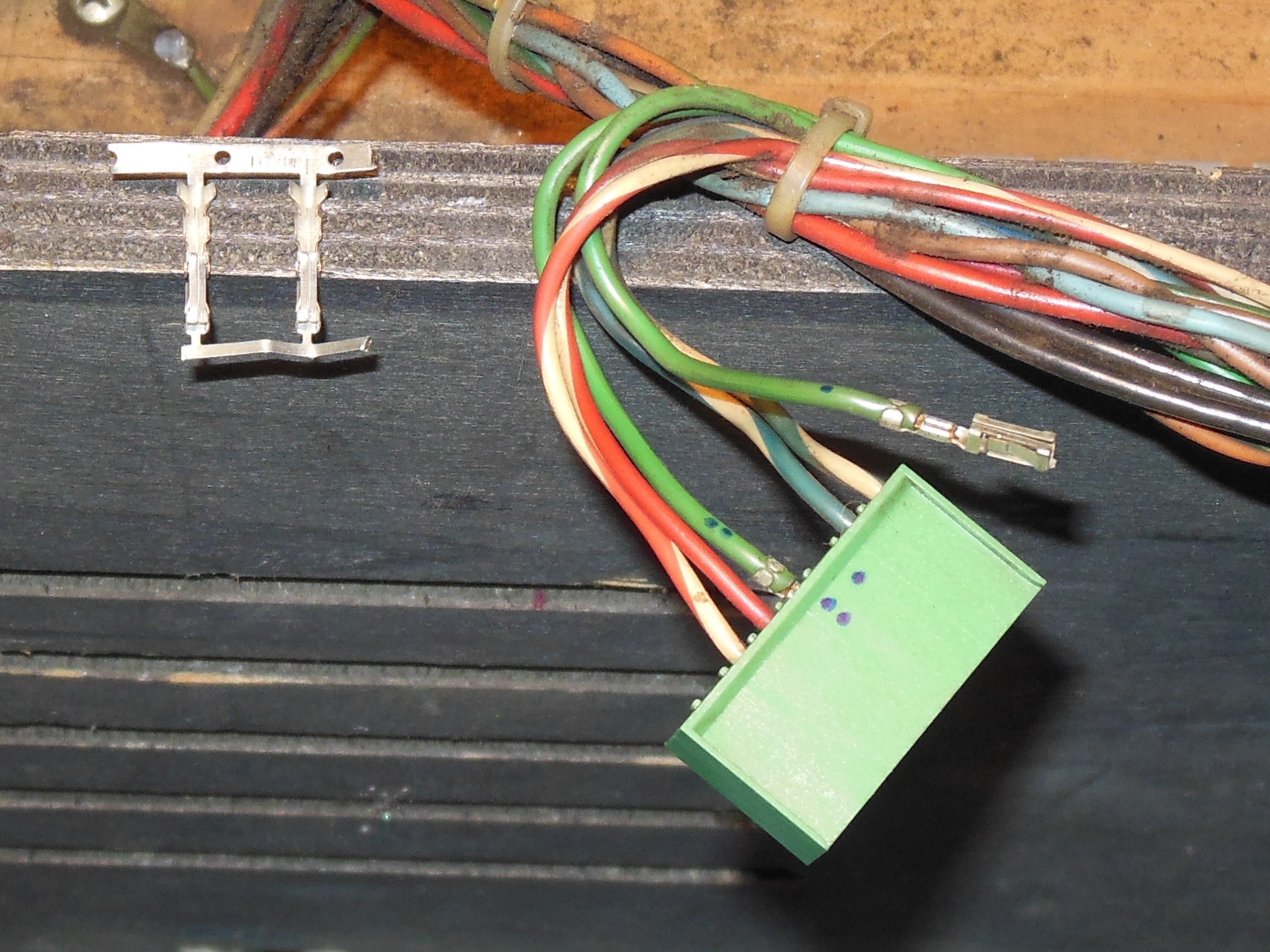
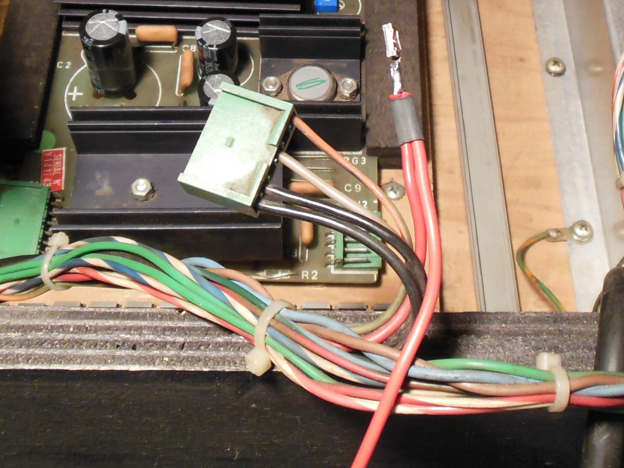
The plan was to wire in a new connector pin along with a second thick gauge wire through to the Konami edge connector. Since the Konami standard pinout only has two +5V edge pins the existing split was separated to allow one wire to feed each finger. With the new connector pin & second power cable the voltage at the game PCB was up to 4.71V (from 4.56V) but the game still wasn't booting in the cabinet :(
|
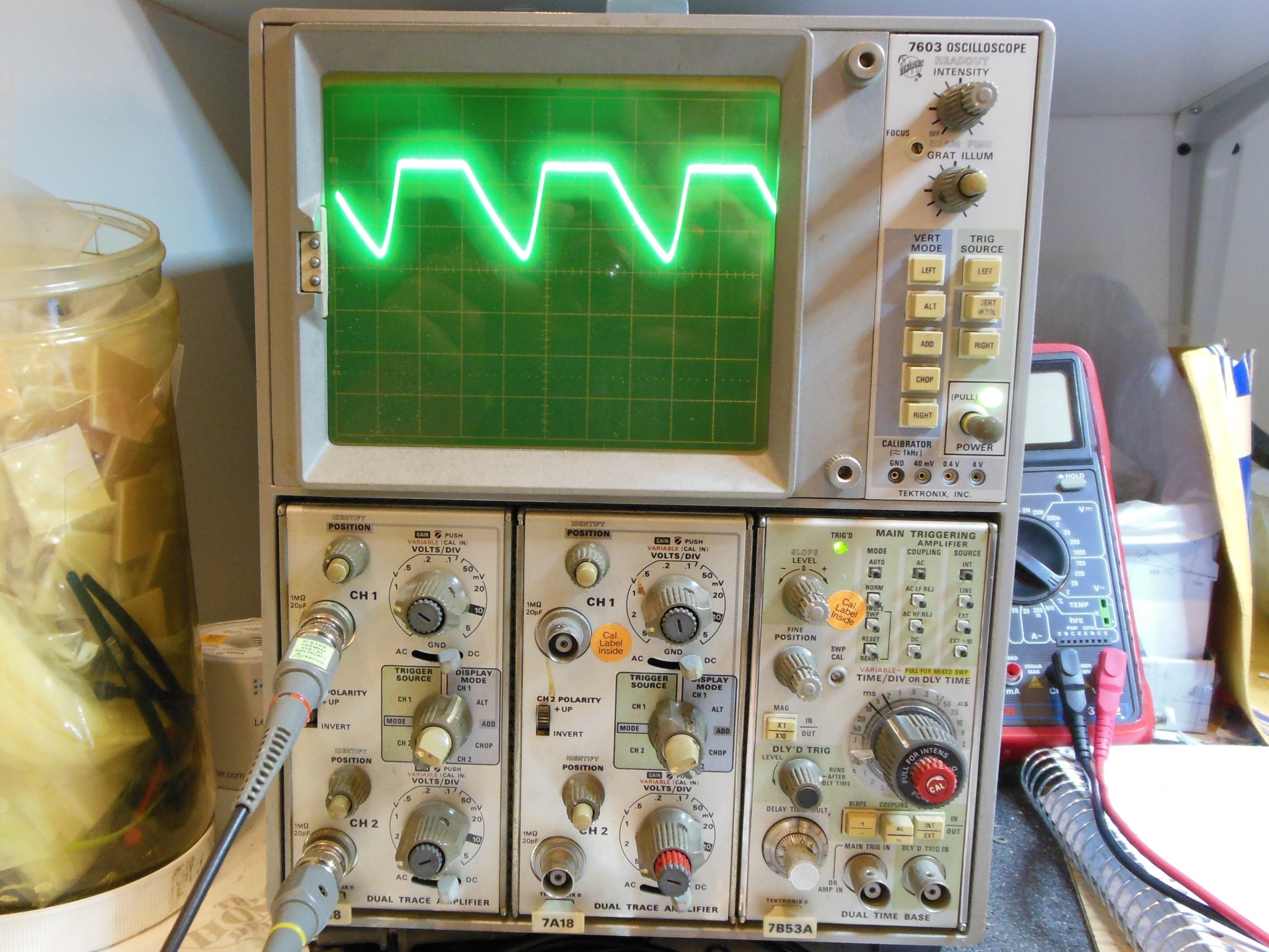
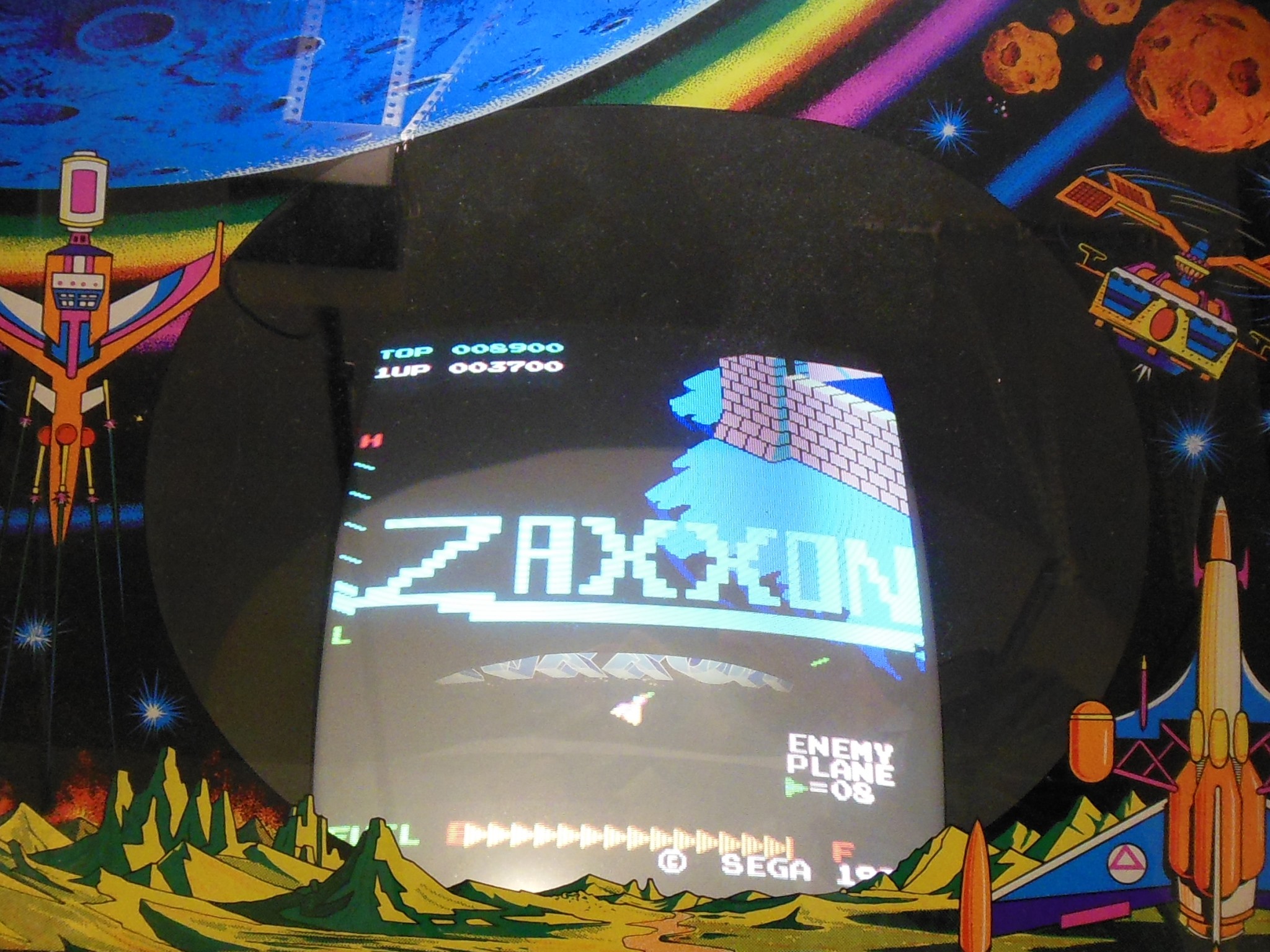
The next step was to look at AC ripple. In AC mode the meter read 0.69V AC ripple on the +5V line. Looking on the scope confirmed very high ripple from ~3.5V to ~4.5V at the game PCB. Given that the linear regulator was being run at maximum and had already had a cap kit fitted recently I suspected that the modern replacement 10,000uF smoothing capacitor was likely more accurate and lower than the original had been. The 1B1126 regulator PCB had more than enough space to accommodate a second 10,000uF capacitor side-by-side in parallel with the first for a 20,000uF total. With that fitted the +5V DC measured 5.02V at the game PCB and finally the game booted & ran OK in the cabinet.
|
The power assembly was reinstalled back into the cabinet and the game run for several hours to confirm power distribution was stable and didn't burn up again. There were two minor issues that I left as is for now - there was a slow moving dim vertical band that crawled slowly across the screen and audio had noticeable background hum. Neither was seemed to be significant enough distractions to be worth investigating yet.