Zaccaria/Seevend/NSM-Lowen Zaxxon Maintenance 2022
16/07/2022 - Replacement bleeder investigation part 2
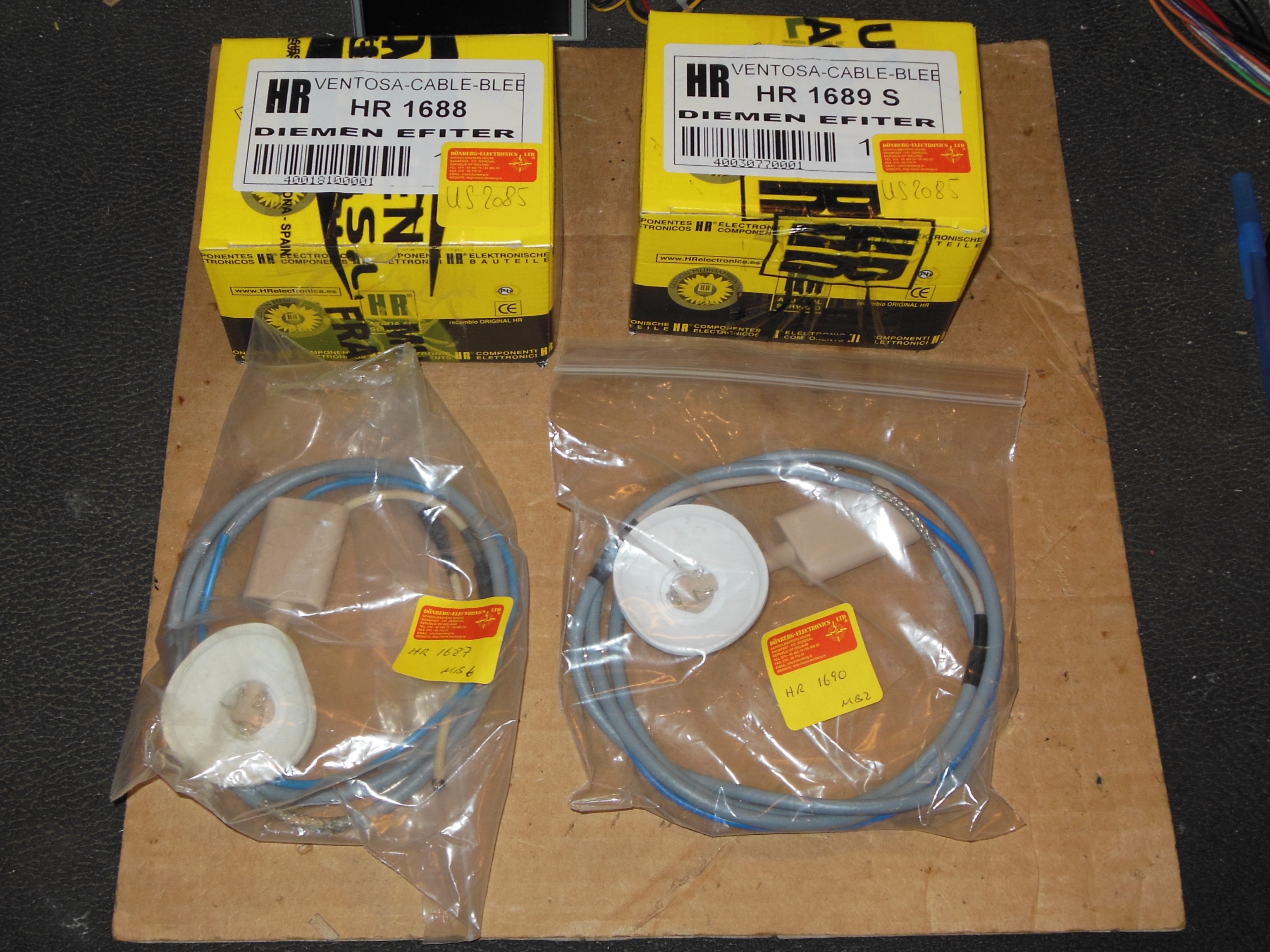
The company had four types of bleeders still available as new old stock that looked
visually compatible with the Hantarex MTC-900 LOPT. These were measured using the same
two methods (voltage and current) as the original with the following parameters:
- Supply voltage = 237.0 VAC
- Meter resistance = 10.25 MOhm
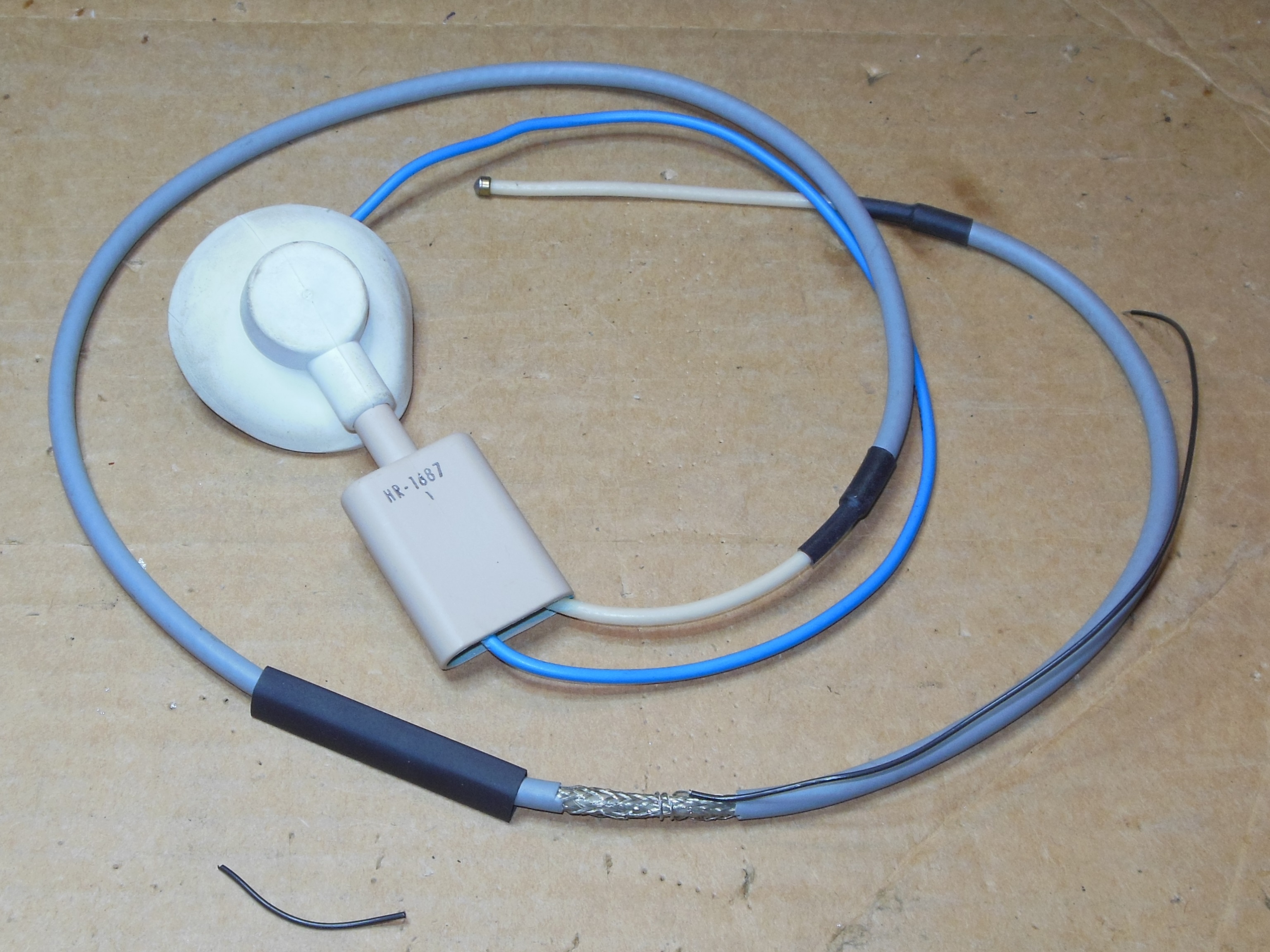
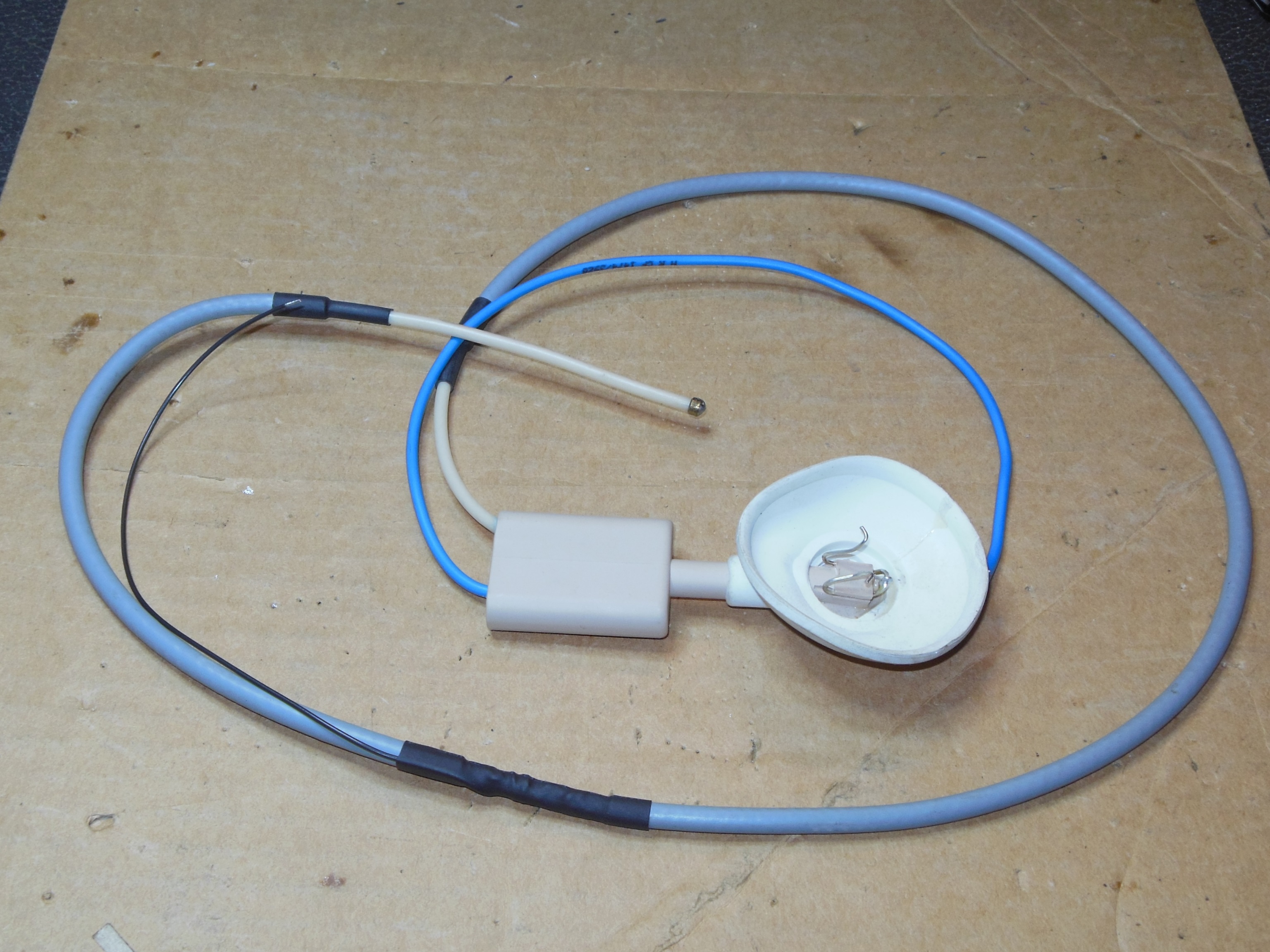
HR-1687
- Bare focus wire
- Focus voltage = 15.6 VAC, resistance = 145 MOhm
- Focus current = 1.7 uA, resistance = 129 MOhm
HR-1690
- Spade focus wire
- Focus voltage = 14.5 VAC, resistance = 157 MOhm
- Focus current = 1.7 uA, resistance = 129 MOhm
HR-1689
- Spade focus wire
- Focus voltage = 14.6 VAC, resistance = 156 MOhm
- Focus current = 1.6 uA, resistance = 138 MOhm
HR-1688
- Spade focus wire
- Focus voltage = 14.6 VAC, resistance = 163 MOhm
- Focus current = 1.5 uA, resistance = 148 MOhm
All the bleeders had approximately similar measurements. Given the inaccuracy of the
measurement method and a theory that the only significant difference between them all was the
focus wire termination and HV lead length, I selected HR-1687 to try first since it already
had a bare ended focus wire matching the Hantarex. All the bleeders had a stripped area on the
HV lead to allow for ground attachment that I modified by shrink wrapping a fly lead to
match the Hantarex fly lead ground connection. I also coiled the fly lead wire around the braid
instead of using solder to prevent damage to the HV insulation.
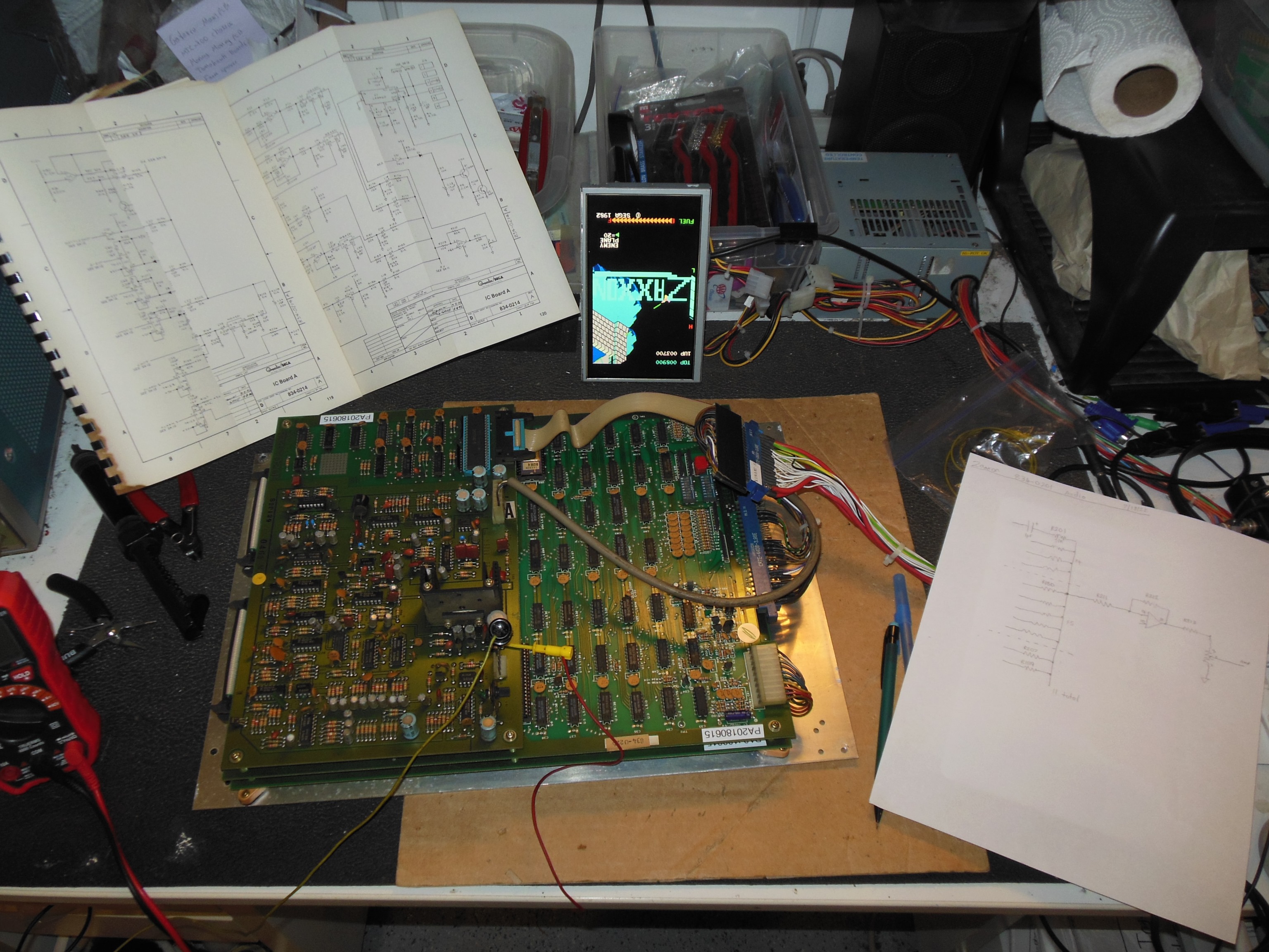
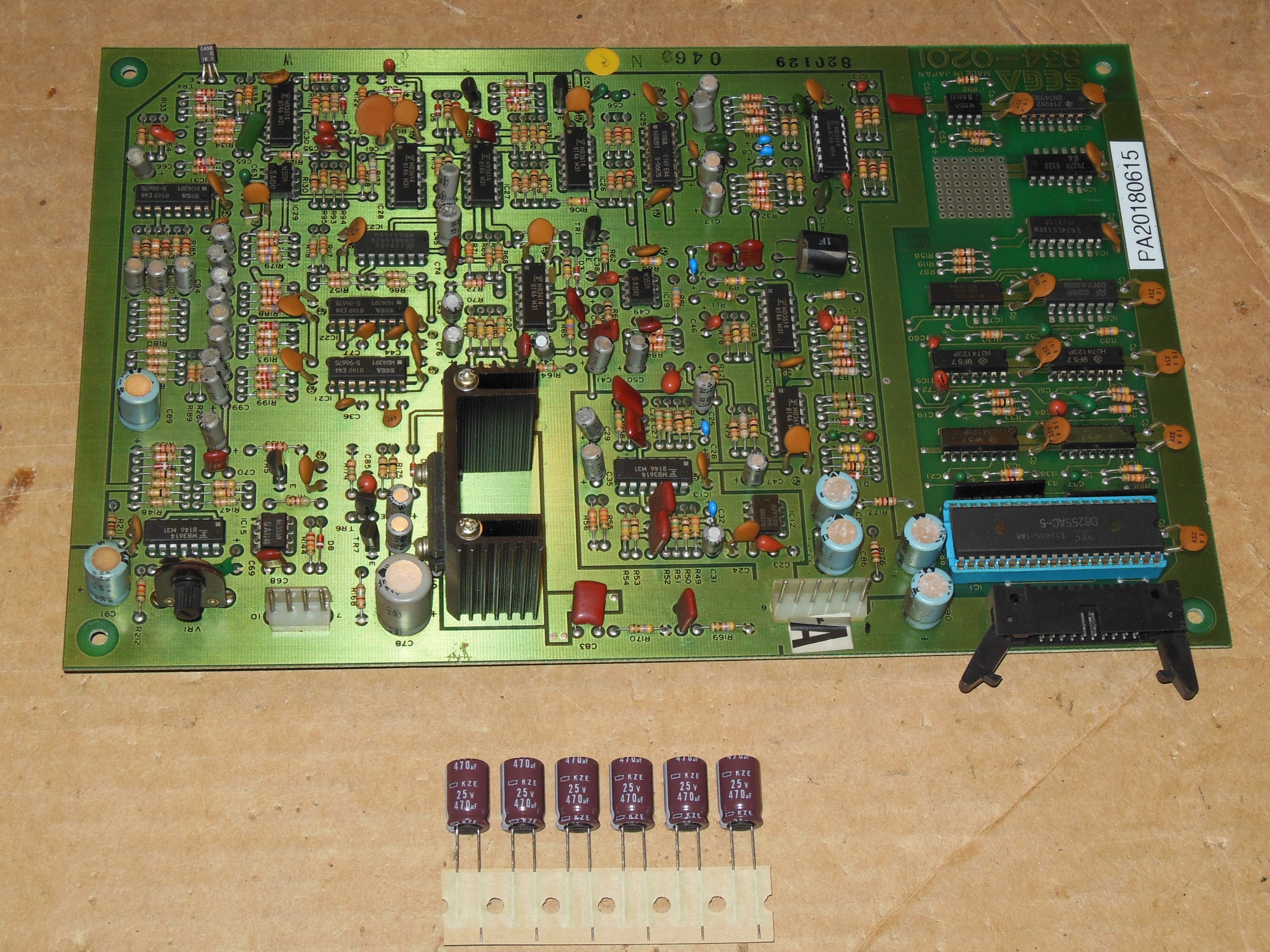
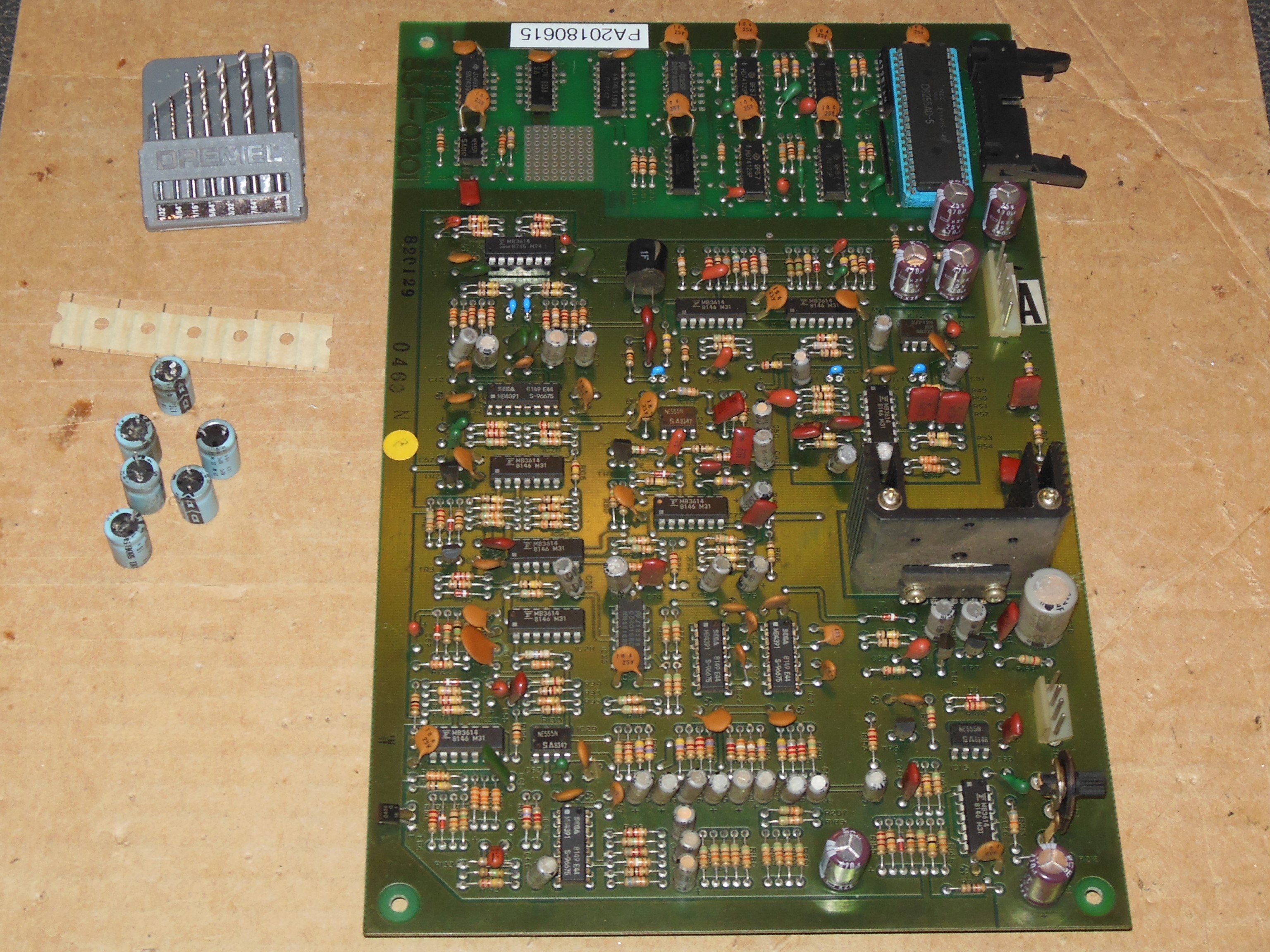
18/07/2022 - Game PCB #PA20180615 repair
Over the years the audio hum had become worse, and I removed the game PCB to test on the
bench to try to determine if it was a cabinet issue or game PCB issue. The Zaccaria
cabinet 1B1126 regulator PCB had already had a cap kit fitted that had made little difference.
There was a large amount of noise even on the bench, and that noise was controlled by the
volume control so it was coming from the pre-amp mix of several game sounds. The schematics
identified net "SJ" as the combined audio net and each individual sound was mixed in via
a 51K Ohm resistor. Shorting "SJ" to ground cut the noise aside from a faint background
"wah-wah". After the short the noise took ~1s to return. Shorting any of the mix signals to
ground had the same effect. Using a scope to try to isolate a specific individual sound
as the source didn't conclude anything - the noise seemed to show on all. I began to suspect
bad smoothing capacitors. The 6 x 470uF capacitors on the +12V and +6V supplies were replaced
and the noise appeared to be significantly reduced. The PCB was set aside to test back in the
cabinet.
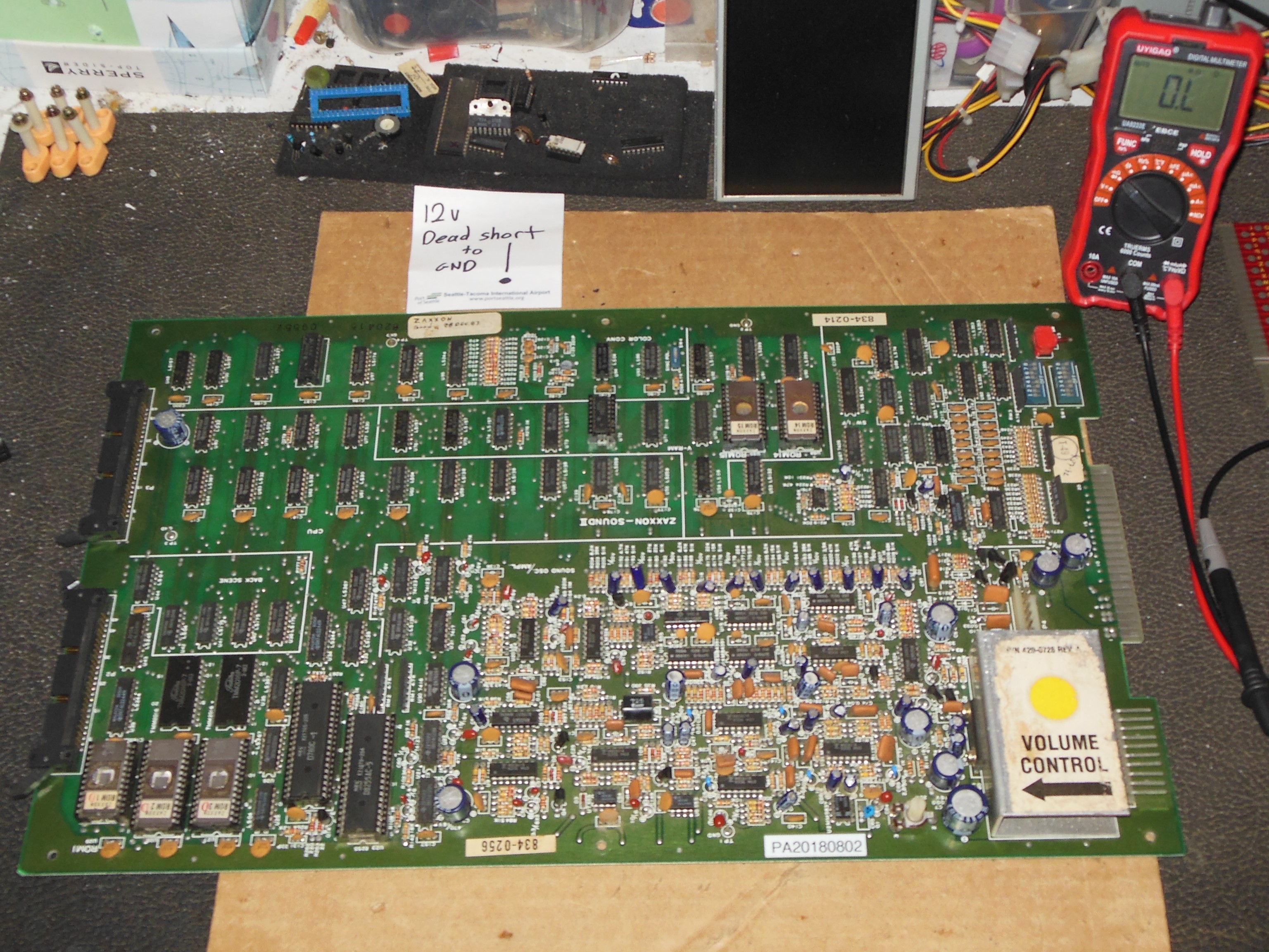
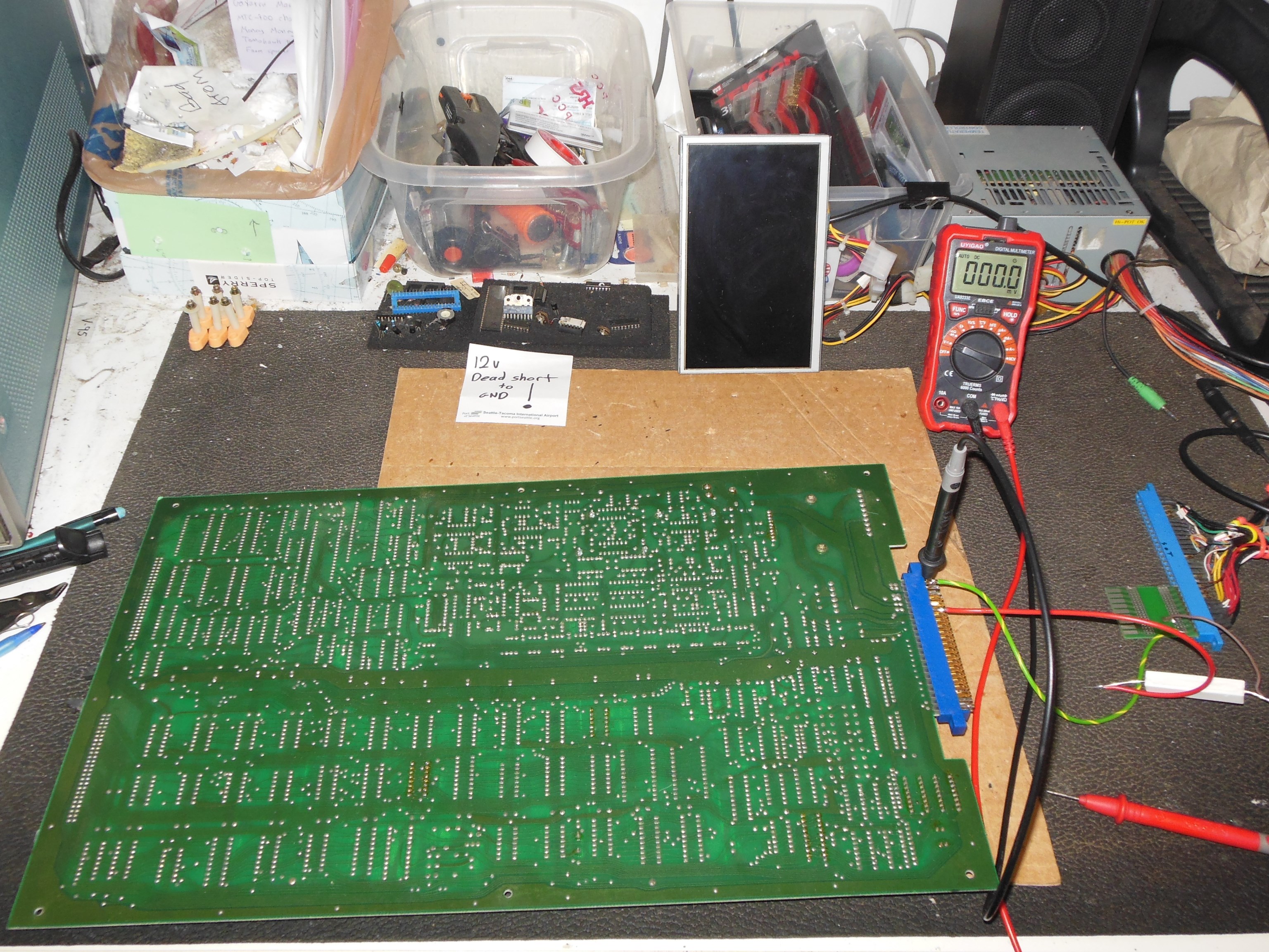
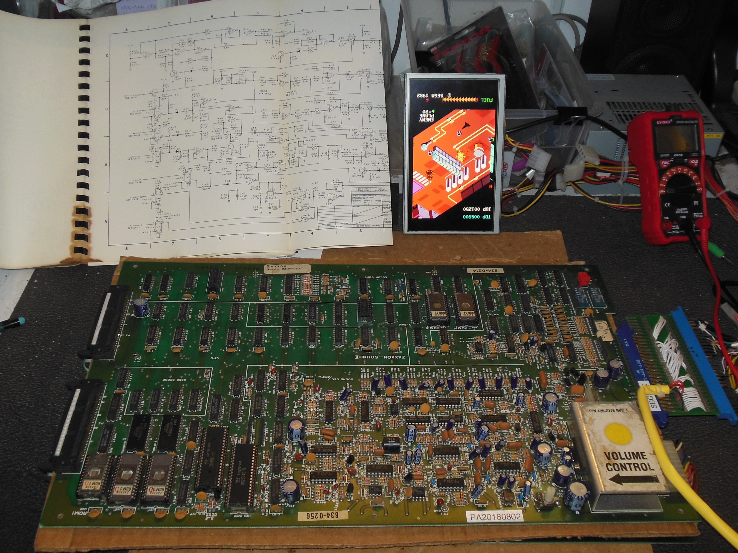
02/08/2022 - Game PCB #PA20180802 repair
Pre-show testing discovered that this spare game PCB had a +12V short to ground. The +12V
supply was used in several places throughout the sound section. I thought about trying
unlimited +5V to blow out the short but on this PCB there was a lot of tracking that could
go up in flames. Instead, the safer plan was to setup a current limited load using the +5V
supply through a 3R6 10W power resistor to give 1.3 Amps maximum and then measure the
tiny voltage drop across the PCB tracking to find the low point at the location of the
short. The voltage measurements on the +12V supply net were:
| Location | Voltage |
|---|
| Capacitor C1 | 88.3mV |
| Amplifier U1 | 84.2mV |
| Capacitor C7 | 78.8mV |
| IC U7 pin 4 | 73.4mV |
| IC U8 pin 4 | 73.2mV |
| IC U20 pin 4 | 73.6mV |
| IC U19 pin 4 | 73.6mV |
| IC U5 pin 4 | 74.4mV |
| IC U4 pin 4 | 74.4mV |
| IC U2 pin 4 | 58.8mV |
| IC U3 pin 4 | 57.9mV |
| Capacitor C64 | 56.7mV |
There was a definite significant drop on the IC U2 & U3 subnet and the tantalum capacitor C64
recorded the lowest voltage point. Lifting one pin of C64 removed the short and replacing
C64 (22uF/16V) fixed the game.
Zaxxon Maintenance 2023
prswan@gmail.com