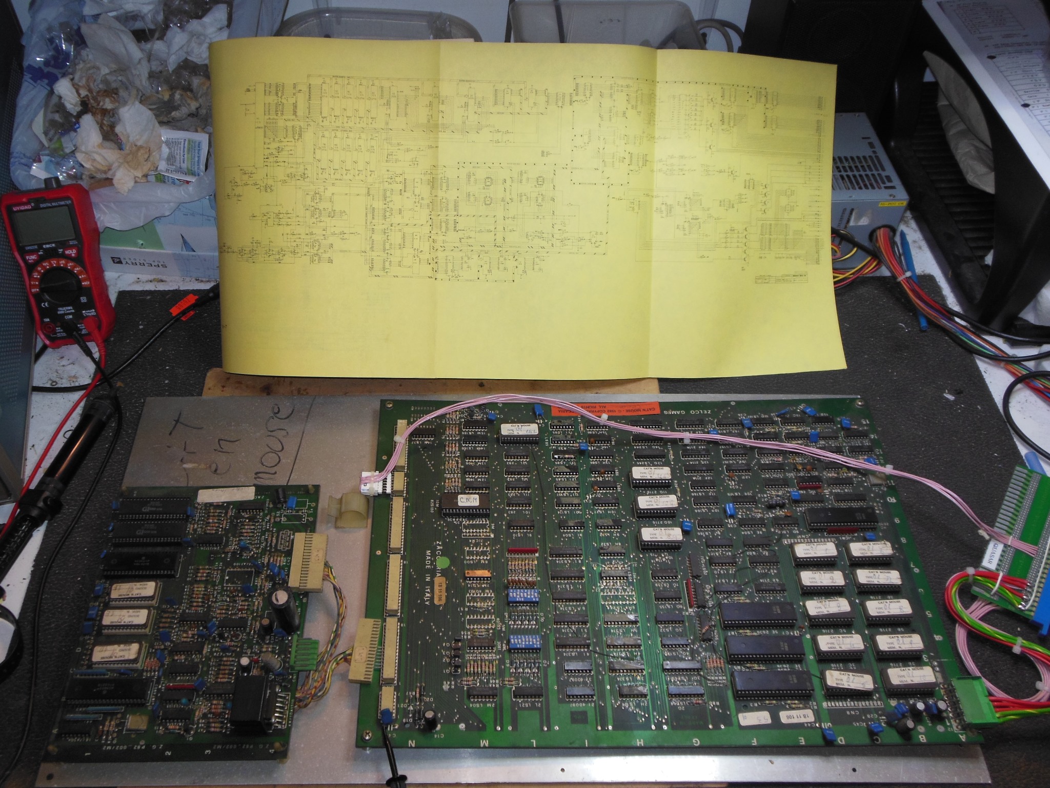

The previous Universal B0 Restoration was used as a base for the application of a Cat'n Mouse kit comprising a marque, game PCB and adaptor wiring.
|
|
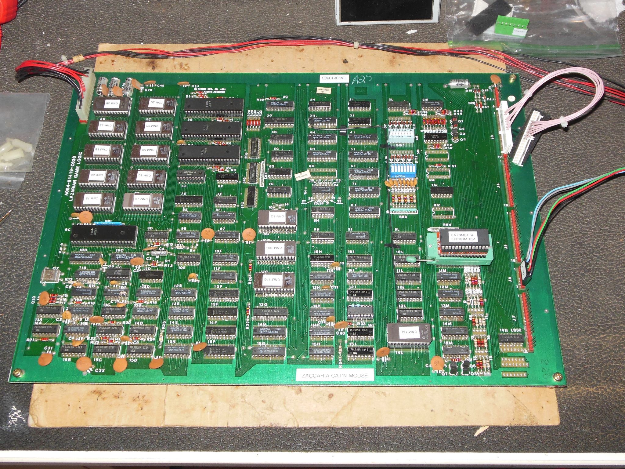
The Cat'n Mouse PCB set was complete and still mounted on the original mounting plate. Initial power on of the main PCB only using the Quasar adaptor found the board running but with graphics issues.


|
The MAME ROM dump of this version of the game was incomplete so PCB pictures and a fresh full ROM dump was read & submitted.


|
Support for Cat'n Mouse was added to the Arduino ICT. The ICT ROM test passed but the ICT RAM test failed IC 6E (2114) and IC 13F (2114). DIP switch reads and 2636 PVI tests all passed OK. Using "RAM Write All AD" and the scope to inspect the signals corroborated that IC 13F looked bad. Replacing IC's 6E and 13F fixed most of the graphics.


|
Overall the graphics looked correct but the colours looked basic. Checking output
pin 13 of IC's 9F/10F/11F looked OK. Some characters still looked incorrect and there
were no bullets visible. With a "RAM Write All AD" the inputs to 10M (82S100) were as
follows:
| 24 - SHELL - idle low | 2 - C3 - active |
| 23 - EFF1 - idle low | 3 - C2 - active |
| 22 - EFF2 - idle low | 4 - C1 - active |
| 21 - COLEFF0 - idle high | 5 - LUM - idle low |
| 20 - COLEFF1 - idle high | 6 - CLN1 - idle low |
| 7 - CLN0 - idle low | |
| 8 - NAV1 - active | |
| 9 - NAV0 - active |
Replacing IC 11I (LS157) did not fix the poor logic low on pin 3. Tracing the input back to IC 12S (LS85) pin 5 as the only source suggested IC 12S must be bad. However, replacing IC 12S still did not fix the poor logic low. With IC 12S pin 5 bent out from the newly installed socket the signal output looked OK. I suspected that the signal was short to something. Poking around the local area with the scope found the same signal on IC 13L (LS283) pin 12. A multimeter confirmed that a direct short existed between them. Tracing the track found it passing between pins 2 & 3 of IC 11I. Removing the socket found a small copper blob shorting the track to pin 3. Since the copper blob was under the solder mask this was a factory PCB manufacturing defect that presumably went unnoticed. Cutting the short fixed the signal and the shells were visible on screen.

|
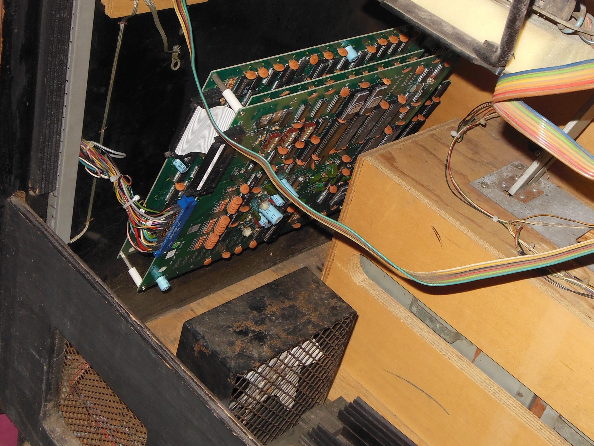
The PCB plate was high and narrow resulting in an awkward fit in this Universal cabinet designed for more conventionally sized PCB mounts. The pure original cabinet likely had different guides to accommodate it and the converted kit Laser Battle had new guides fitted that suggested the main & sound PCBs were separately mounted. This large oversize plate did fit into the lower slot but was too narrow to reach both the front slot and back screw island. In the end it ended up sat in the lower guide and secured with a screw & spacer in the screw island. The Konami connector location was marked on the plate to align with the wiring adaptor.


|
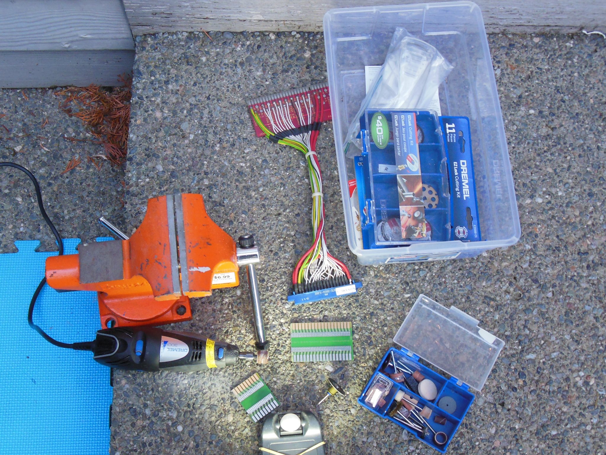
A Dremel was used to trim a JAMMA adaptor PCB to 18-way for the Konami connector. Initially the power & video connectors were wired up to test first. Previously I'd used the Quasar wiring adaptor but with the video wiring per manual the the colours didn't seem correct, a problem that was set aside for now. The main PCB power connector pad was larger than was documented in the manual and the connector pinouts were as follows:
| PCB Pin | Manual Pin | Function | |
|---|---|---|---|
| 1 | |||
| 2 | |||
| 3 | |||
| 4 | |||
| 5 | . | 1 | GND |
| 6 | . | 2 | +5V |
| 7 | . | 3 | +12V |
| 8 | . | 4 | +12V |
| 9 | . | 5 | -5V |
| 10 | . | 6 | +5V |
| 11 | . | 7 | GND |
| 12 | . | 8 | GND |
| PCB Pin | Manual Pin | Function | |
|---|---|---|---|
| 6 | . | 6 | +5V |
| 5 | . | 5 | Speaker + |
| 4 | . | 4 | -5V |
| 3 | . | 3 | Speaker - |
| 2 | . | 2 | +12V |
| 1 | . | 1 | GND |


|
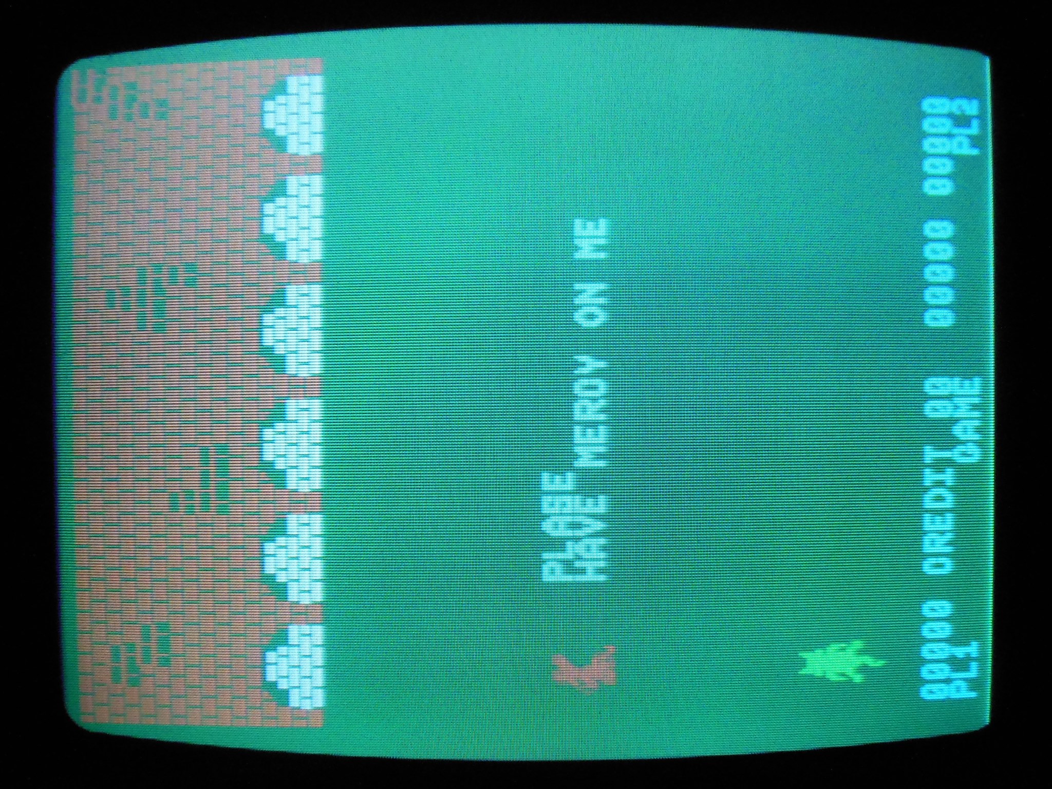
The PCB set was fitted into the cabinet, screwed into place and plugged in. A few basic multimeter checks confirmed no shorts and correct wiring. Cat'n Mouse video output is inverted and the Hantarex MTC-900 monitor supports inverted inputs natively via a small plug on the chassis that was moved over to inverted mode. After a few adjustments the picture looked good, though still with dubious colours.


|
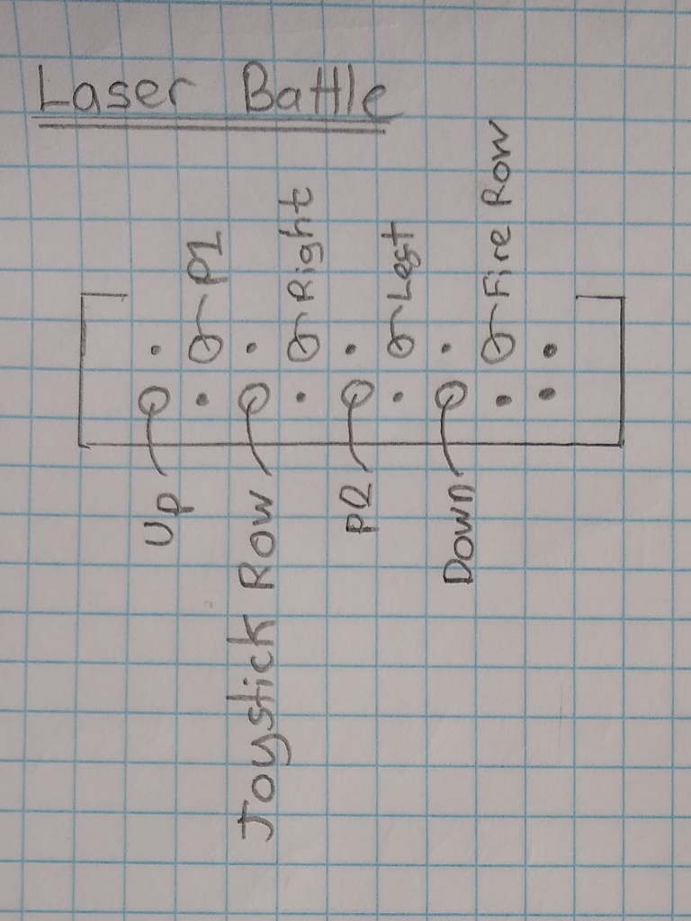
Conversion of the Universal B0 control panel to matrix input for Cat'n Mouse first needed a definitive pinout for that connector and some hints from the converted Laser Battle control panel. In both cases the manuals didn't describe a pinout that matched either panel. The plan was to use the button 1 and button 2 signals as the matrix ROW lines - as it turned out this was exactly how Zaccaria pinned it.
| Laser Battle Control Panel Pinout | Universal B0 Control Panel Pinout |
|

|
The row mapping was wired through as follows:


|
Reproduction button springs finally arrived. They were a little bit stiffer than the original springs - likely the next wire diameter down (0.6mm) would have been spot on. That said, they were good enough for the player start buttons.

|
1N4148 diodes were fitted on all of the leaf switches and the wiring adjusted to match the Laser Battle configuration noted above.


|
Though the manual shows a separate connector for the coin switch wiring enough signals for it are also present on CN4 allowing a single connector to be used for all inputs. The Universal B0 uses a 1B1185 credit PCB with common ground credit input that would remain un-matrixed as is on the adaptor using COIN 1 that was unused on any other matrix row.
| Signal | CN4 J4 Pin | CN5 J5 Pin | CN4 J4 Function | CN5 J5 Function |
|---|---|---|---|---|
| COL 7 | 13 | 9 | DOWN | TILT |
| COL 6 | 6 | 3 | UP | COIN 2 |
| COL 5 | 9 | 8 | RIGHT | SERVICE |
| COL 4 | 11 | 5 | LEFT | |
| COL 3 | 10 | 7 | COIN 1 | |
| COL 2 | 12 | 4 | COIN 3 | |
| COL 1 | 17 | 11 | PLAYER 2 | |
| COL 0 | 16 | 12 | PLAYER 1 | |
| ---- | ||||
| ROW 0 | 15 | 10 | FIRE | |
| ROW 1 | 14 | 14 | ||
| ROW 2 | 7 | - | JOYSTICK |


|
The completed adaptor was tested in the cabinet and the 1B1185 credit PCB was set to 1 coin 1 play where possible on all coin slots.

|
In the cabinet the sound output had clipping on the bass for which the first attempt at remediation was a cap kit on the audio board. Note that the silk screen was misleading on the + and - markings in places so special attention was needed on cap polarity.
| Location | Value | |
|---|---|---|
| C55 | 100uF/16V | |
| C52 | not fitted | |
| C30 | 100uF/16V | |
| C37 | 100uF/16V | |
| C33 | 47uF/16V | |
| C36 | 2200uF/25V | |
| C32 | 0.22uF/35V | Tant. |
| C27 | 4.7uF/35V | Tant. |
The first round of electrolytic replacements didn't fix the bass clipping. Replacing the tantalum capacitors with non-polar ceramics, based on design errors on other Zaccaria games causing them to fail, also didn't fix the issue. Replacing the TDA1510 audio amplifier IC did fix the bass clipping and the audio now sounded excellent.
|
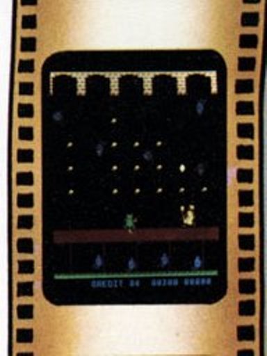
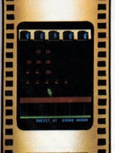
MAME and the small screen shots shown on the two Cat'n Mouse flyer scans had approximately the same colour palette confirming something was incorrect on my setup.
As part of the colour fault finding IC 10M (82S100) was dumped using the
Data IO UniSite. Due to dump format differences between this PLA dump and prior dumps
some investigation was needed to confirm the IC was good. The net result of that
was published in:
DataIO UniSite 82S100 Dumping.pdf
The complete set of 82S100 dumps from Zaccaria Laser Battle, Cat'n Mouse and
Money Money/Jackrabbit were dumped and converted into various formats:
Zaccaria 82S100 dump set
| Signal | Lazarian | Laser Battle | Cat'n Mouse | Quasar |
|---|---|---|---|---|
| SYNC | 1 | 1 | 1 | 1 |
| BLUE | 2 | 4 | 4 | 3 |
| -key- | 3 | |||
| GREEN | 4 | 3 | 3 | 4 |
| RED | 5 | 5 | 5 | 5 |
| +5V | 6 | |||
| GND | 7 | 7 | 7 | 7 |
Using the various manuals to pull together all the pinouts for several games found a couple of interesting points. First, Midway Lazarian has a different video pinout than the equivalent Zaccaria platform. Second, Quasar had green & blue swapped. Comparing the prior photos from Cat'n Mouse on the bench with the Quasar adaptor and with the Cat'n Mouse adaptor appeared to suggest that the Zaccaria Cat'n Mouse manual was incorrect and the video pinout was the same as Quasar.


|
With the Cat'n Mouse adaptor re-pinned to match Quasar the colours finally looked correct in the cabinet.


|
After 8 hours of run time the monitor lost sync. Adjustments were able to slow the roll closer to sync but there was no indication of any sync lock.

|
I'd seen the lack of sync lock before and speculatively decided to pull & test the sync input transistor TR1 (BC237B). The transistor tested bad and was replaced. With the chassis back in the cabinet the monitor was working OK again.


|
Though the monitor was working the game itself showed 1 credit on power on and no further credits could be added. The credit button did bump the coin counter, however. On the bench the credit output was permanently stuck down. Checking IC2 (8035) pin 37 (P26) output saw it pulse low on credit. Moving on to IC6 (LS00) pin 6 output saw it pulse high. The credit relay drive transistor TR1 (BC548) appeared to show no response to the low pulse. Replacing TR1 and diode D18 (1N4148) fixed the credit output.
|
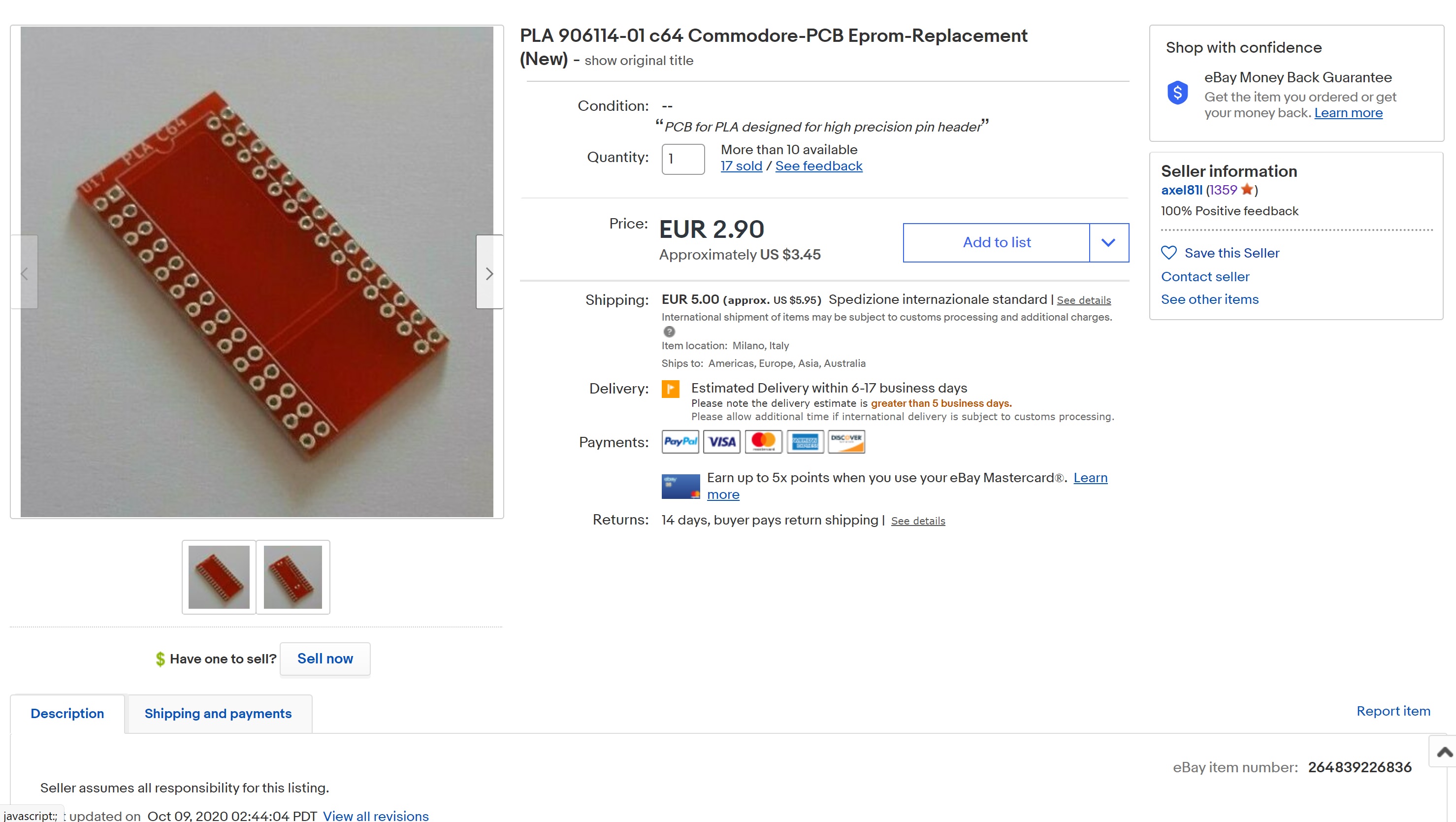
Previous research on the 82S100 had discovered that the Commodore 64 home computer had used an 82S100. The C64 community had extensively researched replacement options and one of the first such options was an adaptor to convert the 82S100 pinout to match a 27512 EPROM and a small C program to flatten the PLA into a binary file for the EPROM. The plan was to utilize that same adaptor to construct a Cat'n Mouse 82S100 replacement for the conversion of a Midway Lazarian game PCB into a spare Cat'n Mouse main PCB. Blank C64 PLA to EPROM PCBs were ordered from eBay.


|
One small hiccup was that the adaptor PCB was manufactured to use thin round pin headers I had to specially order. The original 82S100 was 50ns but the fastest EPROMS I had to hand were 120ns. There were 45ns 27C512 on eBay I could order if the adaptor worked OK.


|
A clean working Midway Lazarian game PCB was selected as the starting point.


|
A complete set of Cat'n Mouse EPROMS were programmed (using 2532 to replace 2716 since I was short of 2716). The game booted up OK on first power on with a couple of issues. First, there was some snow around the edges of some graphics. This I attributed to the slow 27C512 EPROM. Second, the sprites were not quite correct. This I attributed to the missing sprite bank control signal, a wire hack present on the original game PCB.


|
There were two hacks to apply to the Lazarian PCB. The first was the sprite bank select for the larger sprite ROM at 14L and the second was applied to IC 13I, a 74LS85 (that I suspect adjusts the shape of the bullets).


|
Though it looked like Midway directly copied the PCB and changed the connectors, a more detailed side-by-side comparison found a couple of pinout differences. The video connector J6 pinout was slightly different that necessitaed building a small adaptor to convert it to match the Cat'n Mouse wiring.


|
The sound PCB connector J3 was 19 pins on Lazarian and 18 pins on Zaccaria. For this connector I built a new sound PCB harness.


|
In addition to the slightly different connectors, the PCB mounting holes were also in different positions. A second set of PCB mounting holes was drilled in the mounting plate and the converted Lazarian PCB fitted.

|
The conversion was complete aside from the power connector for which parts were on order from Mouser.


|
Previous repairs to the sound PCB had the game sounding great on the bench but still poor in the cabinet. I didn't hear anything off with Gyruss previously, but Gyruss was not as bass heavy as Cat'n Mouse. Trying Gyruss back in the cabinet found the sound to be poor and I suspected the cabinet speaker was bad.


|
Removing the 4 nuts securing the speaker in the cabinet released both the front grill and speaker, a 6 inch Bukdoo 6 160DF06 4 Ohm 7W speaker. Some gentle pressing confirmed that the voice coil was stuck full out. Firmly pressing it down released it, but it was still catching somewhere and the paper cone had become deformed into a permanent out position, having likely being stuck out for decades.

|
There were no search hits on the original Bukdoo speaker but I was able to find a few others of the same size and mountings on eBay. A replacement Foster 46408-20 was ordered.


|
On arrival the Foster speaker was a perfect match in terms of size & shape to the Bukdoo. Alas, checking the replacement speaker on the bench found it open loop and it was returned to the seller.

|
Another replacement Foster speaker was ordered from eBay.


|
I considered making a cabled power adaptor from the Midway Lazarian Molex power plug to the Cat'n Mouse AMP Modu power socket but since the pitch of the two was the same decided to try to make a rigid direct adaptor. The idea was to directly fit the Molex pins to the AMP pins in close enough alignment that it could be plugged into the Molex housing all in one. A small G-clamp held the connector in place to allow the pins to be accurately positioned. After all the pins were fitted, the assembly was pressed onto the Molex housing. I had doubts about this method but it turned out very solid, working without issue on the bench and in the cabinet.


|
In the cabinet the snow from the EPROM 82S100 adaptor was barely noticeable and the game looked & played OK.

|
Bench testing of the second replacement speaker confirmed it worked and it was fitted into the cabinet. There were still some intermittent sound issues, however. The speedy mouse music and dog barks weren't working properly.

|
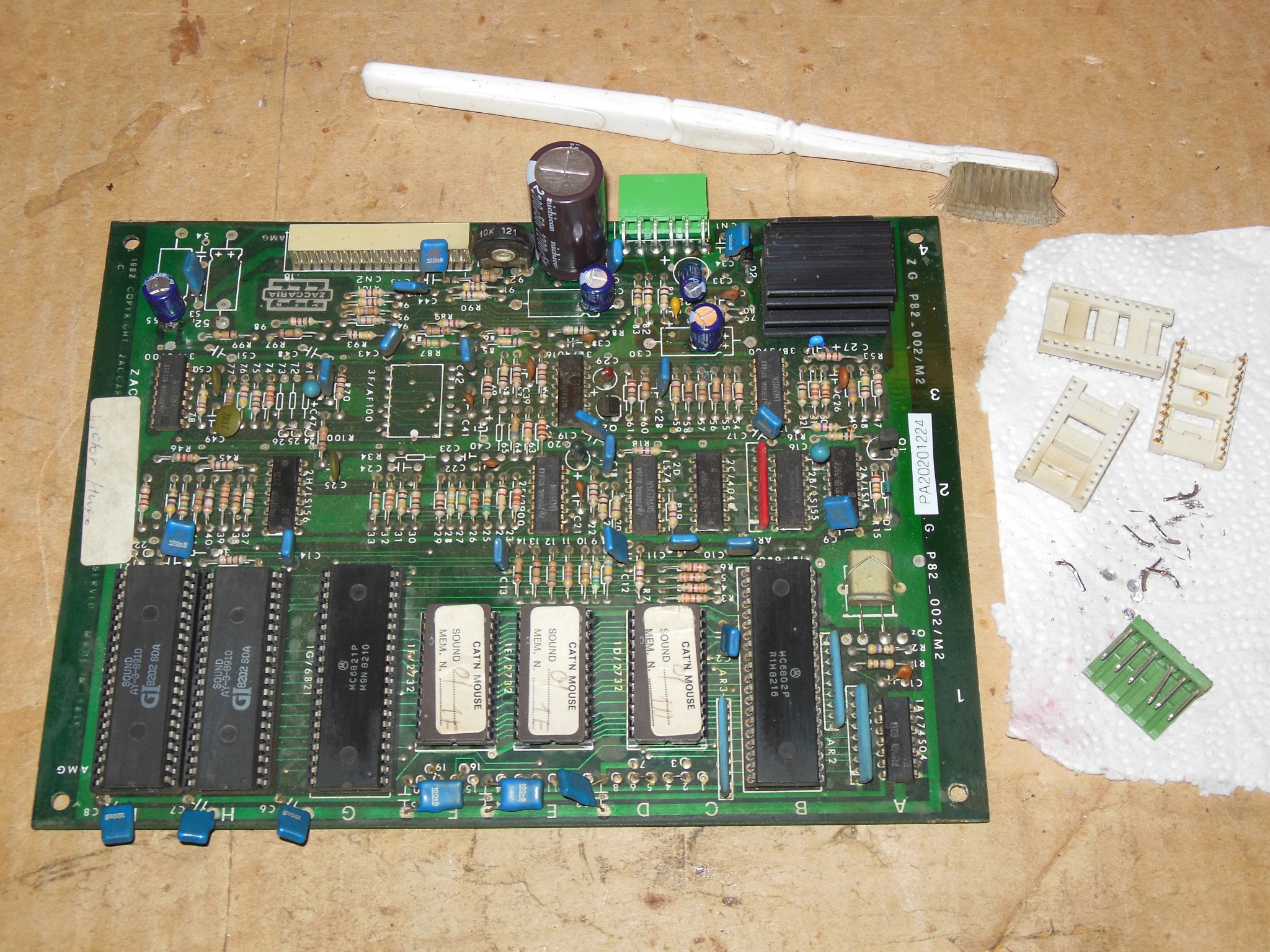
On the bench the sound board had the same issues as it had in the cabinet. The intermittent white EPROM sockets and broken power connector were replaced but the sound issues were still present. Swapping in spare a 6821 and 6802 also didn't fix the sound issues. Cross-swapping the two AY-3-8910 sound generators caused the sound issues to change. Swapping in a new AY-3-8910 confirmed one of them was bad and the sounds were fixed.
A video of the Zaccaria Cat'n Mouse game in action on this cabinet.


|
Another 8 hours of burn in testing didn't encounter any more issues.


|
Whilst the picture was still good after 8 hours a small tweak to the brightness & focus made it excellent.

|

|
The Winbond W27C512-45ns EEPROMs arrived. Whilst the DataIO UniSite software I had didn't support the W27C512 it did support the W27E512 that appeared to be identical (according to the Winbond datasheets) and it was programmed without issue. In the Cat'n Mouse converted Lazarian PCB the noise seen with the slower EPROM was gone and the graphics looked excellent.