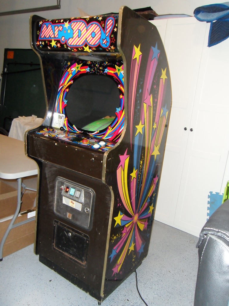
Zaccaria/Associated Leisure Mr. Do! Restoration
Background
This was a game that I helped a fellow UKVAC collector buy in the 90's before
I became a Zaccaria enthusiast. He left the country and the game came to me.
For a long time I thought this was just an operator conversion of
a Zaccaria Universal (not Universal the game company but universal as in for
any game) cabinet but then a flyer with this cabinet for Mr. Do! surfaced.
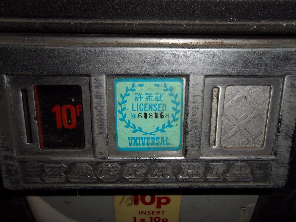
My game has Associated Leisure serial numbers on the parts inside it.
Associated Leisure Mr. Do! Flyer
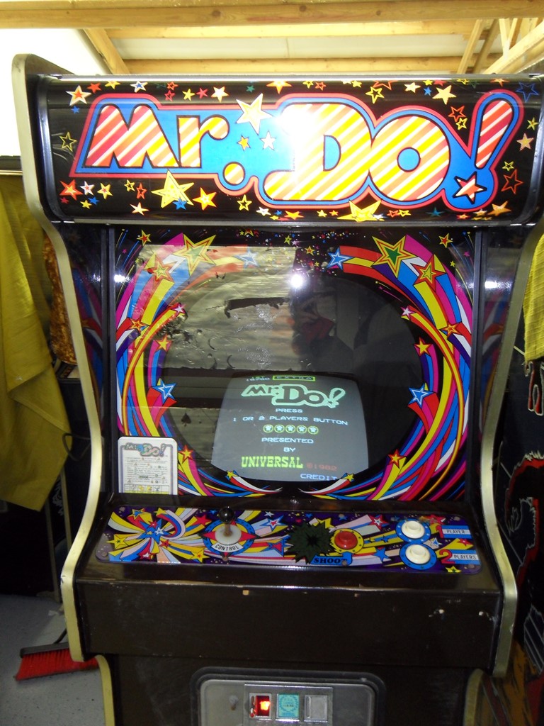
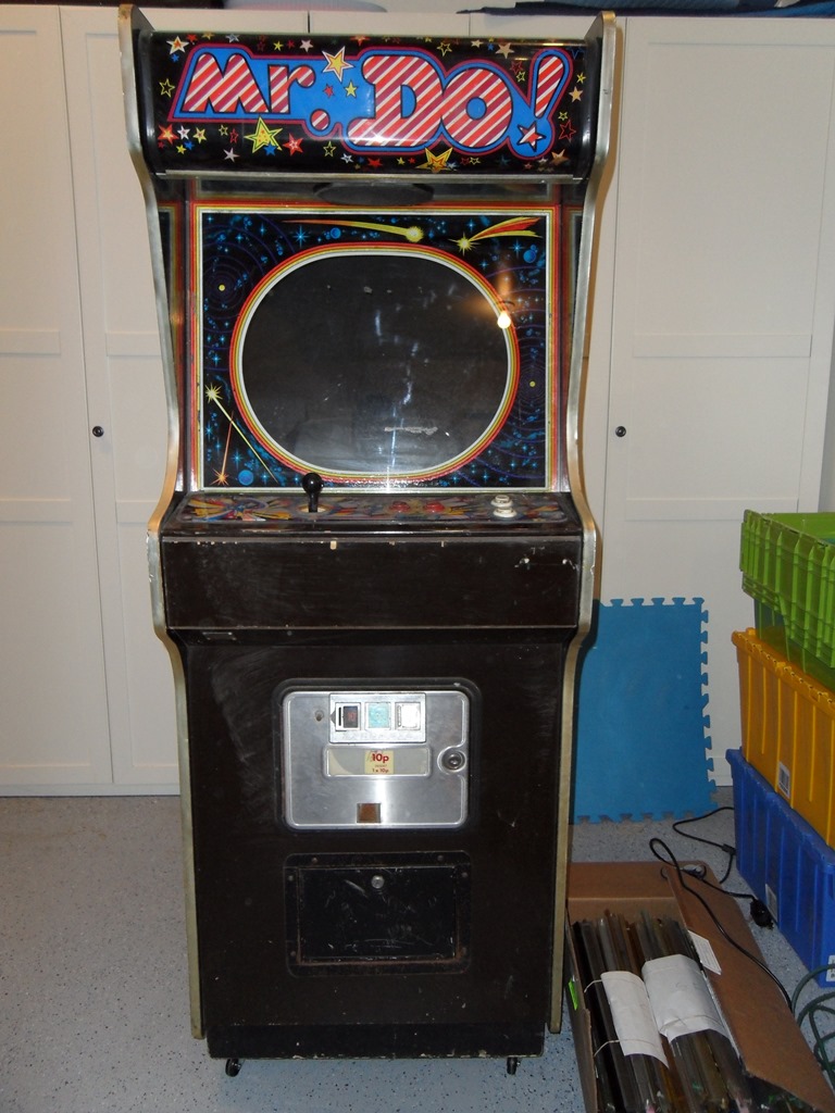
21/10/2012 - Initial assessment
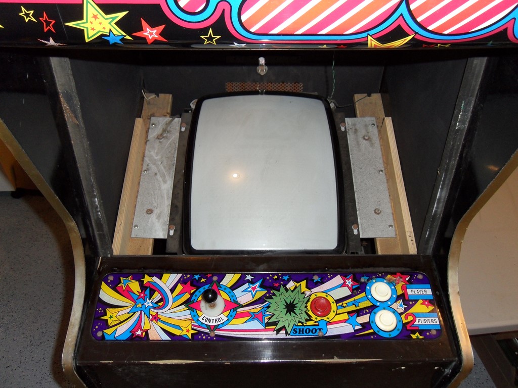
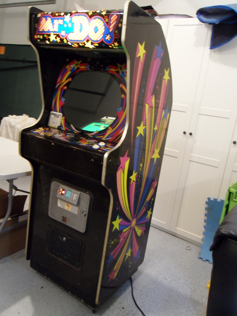
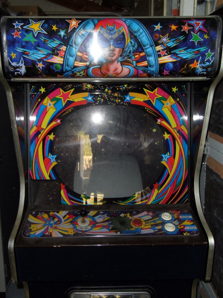
The cabinet looks basically solid. There is a small crack in the marque
and the original glass was broken a while ago so it has a Quasar glass in it now
(I have a Phoenix that has the star glass in it that I can swap with this one to
correct both games). The cardboard monitor surround is also torn up.
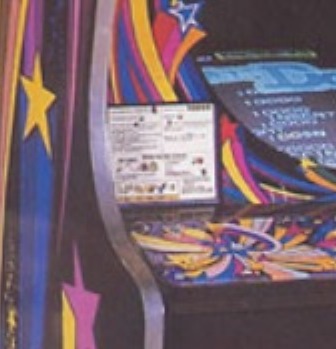
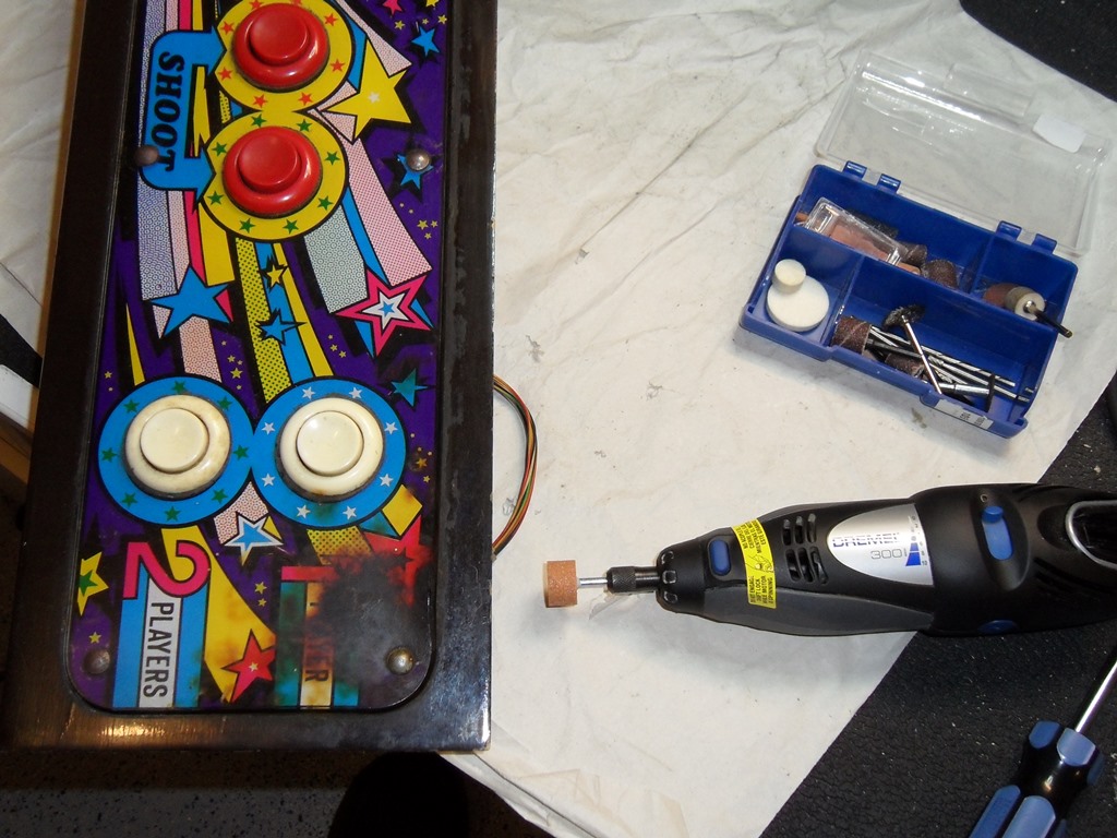
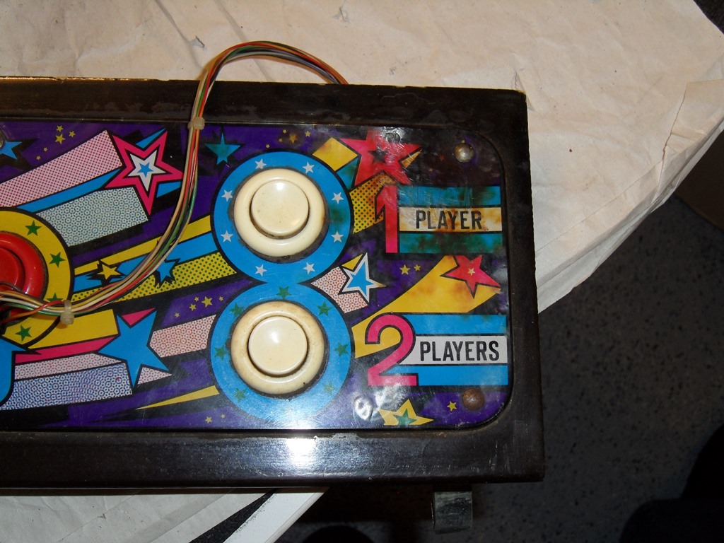
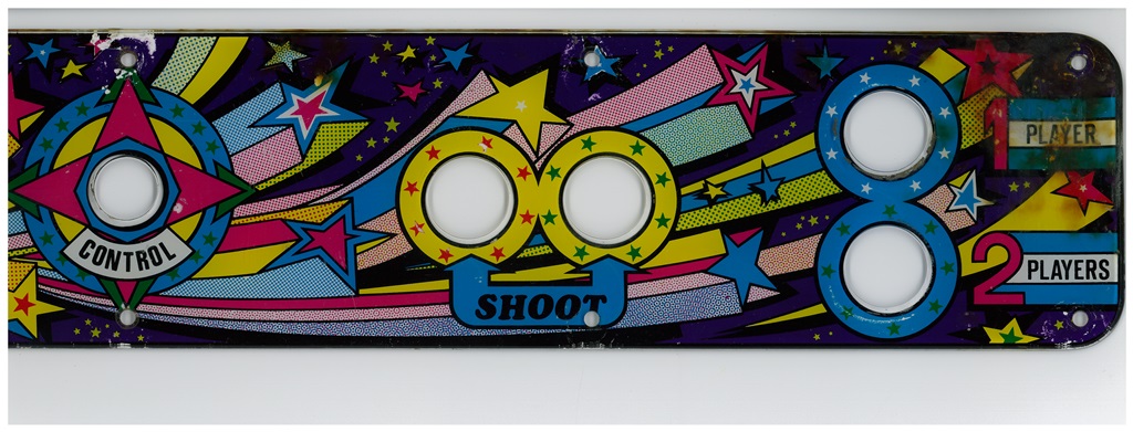
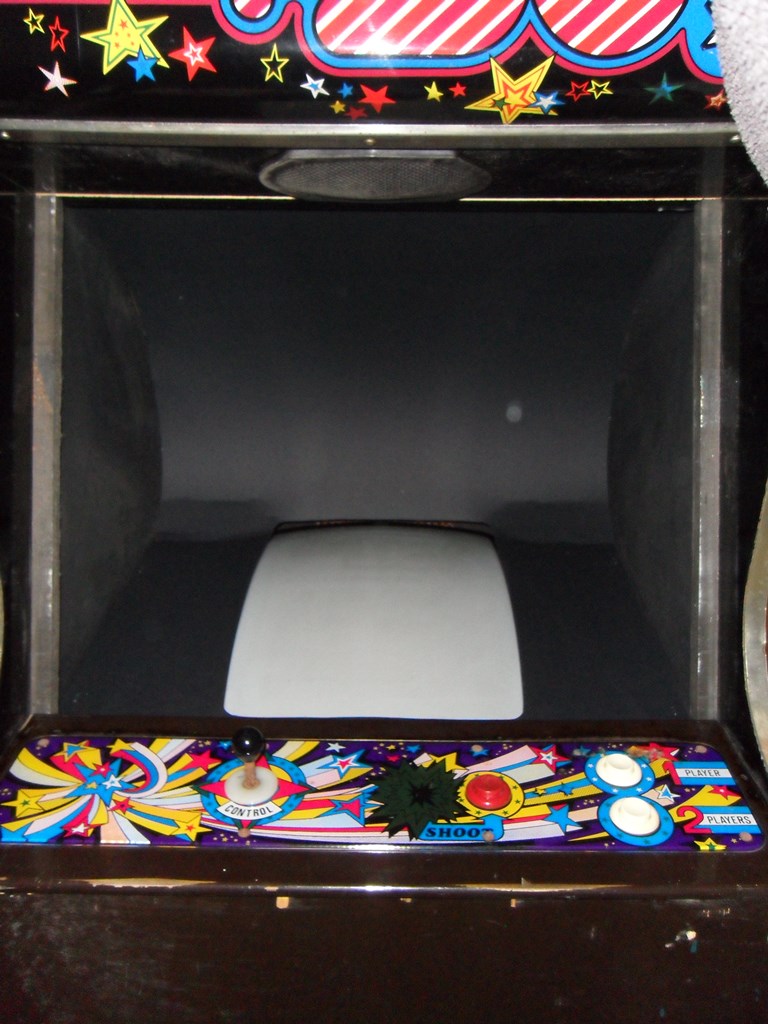
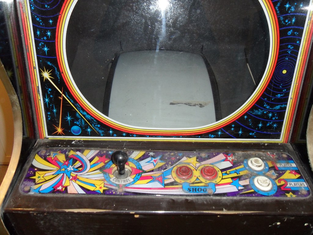
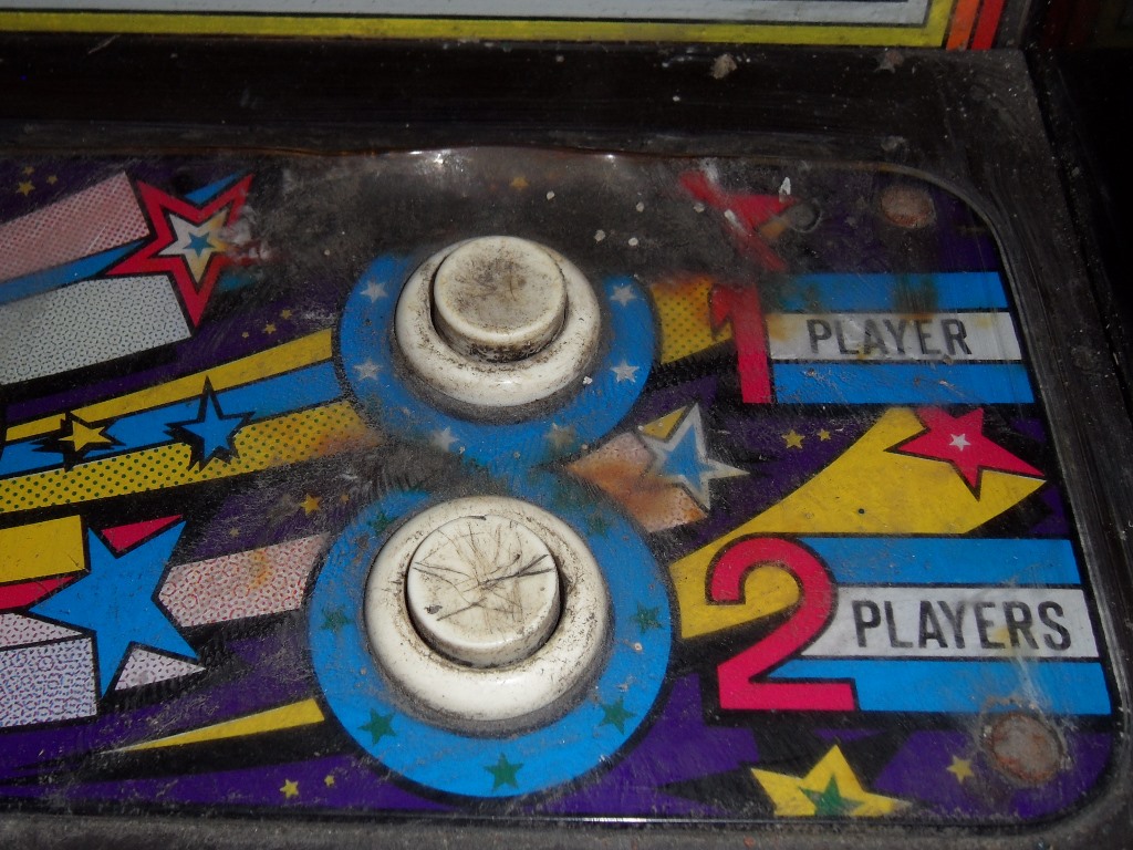
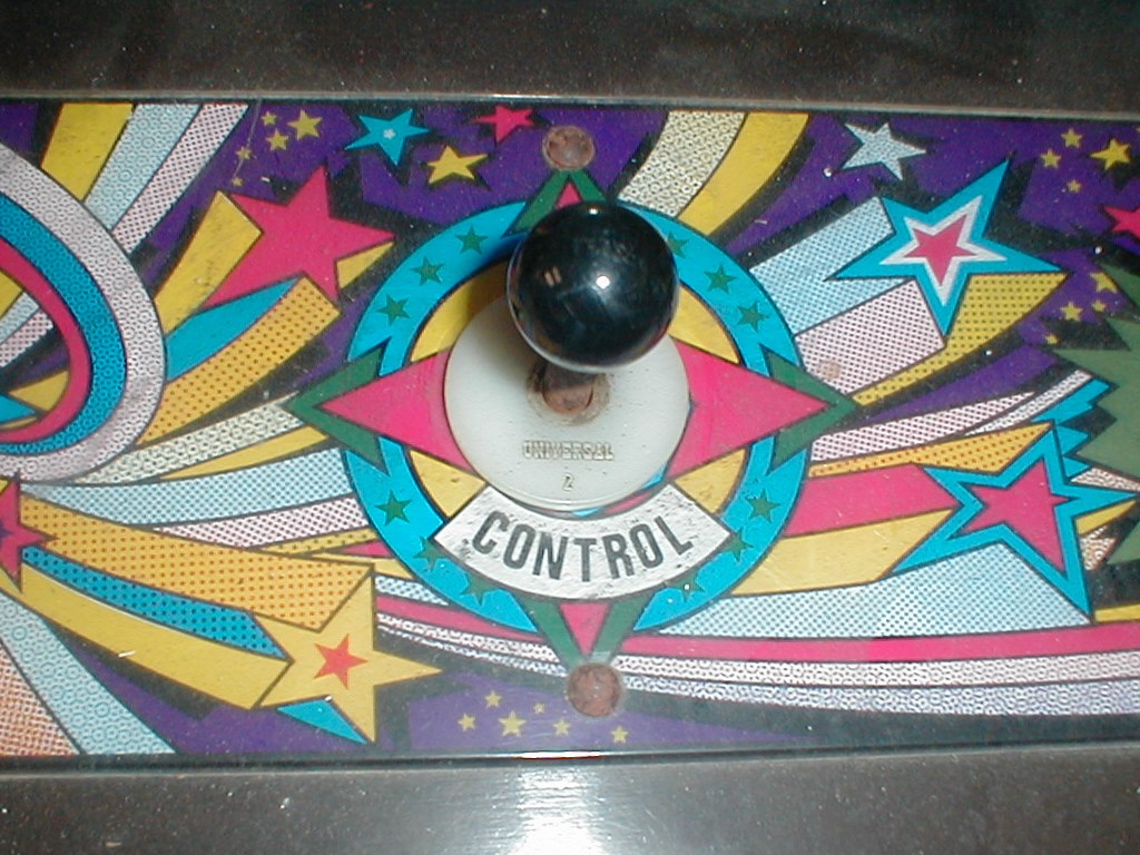
The control panel woodwork has been so well used the paint has been worn
away down to the wood on the edges. The joystick has been changed and
the holes in both the wood and the overlay widened to accommodate the
replacement. The player select buttons are vandalized and the control panel
overlay has the worst cigarette damage I've ever seen :(
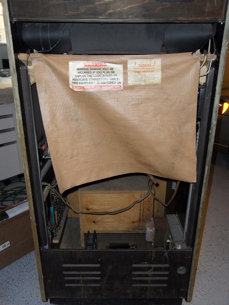
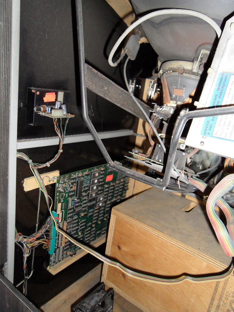
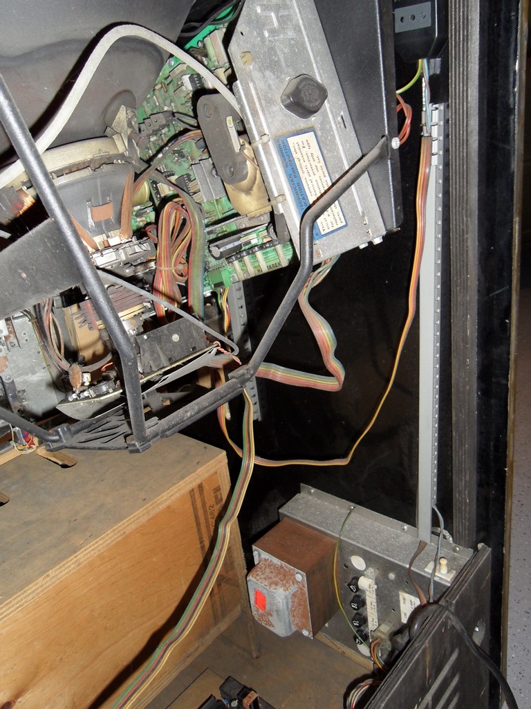
22/10/2012 - Internal assessment
Looks like I have a full set of keys for this cabinet including the original
Zaccaria stamped keys :)
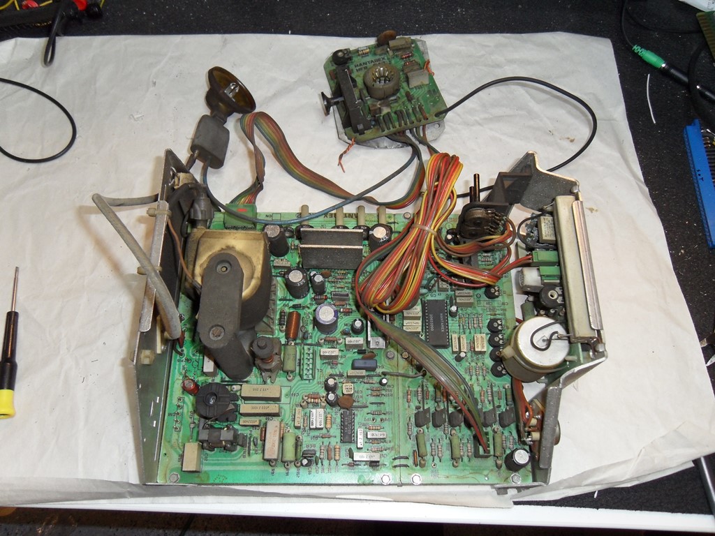
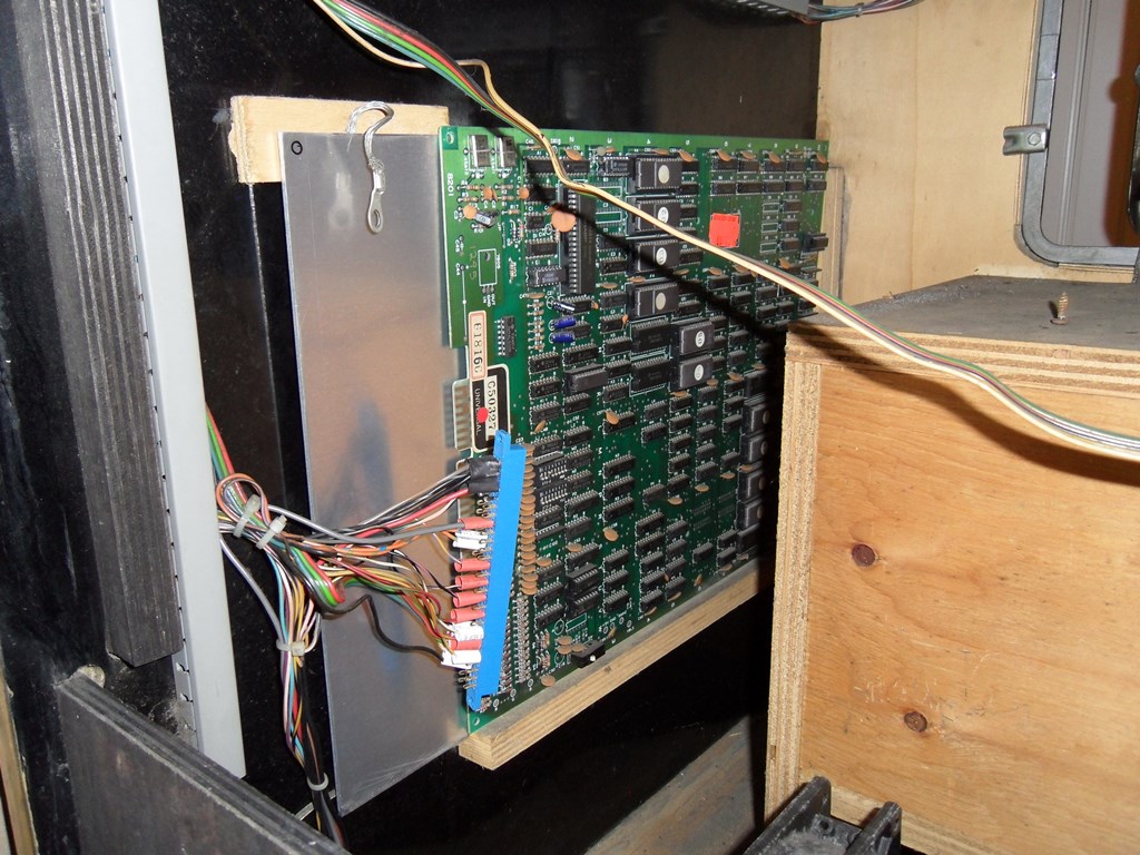
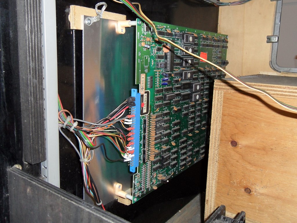
As far as I can tell it looks like the internals are complete and all
original. There's a wire broken off the audio amplifier and I'm not sure
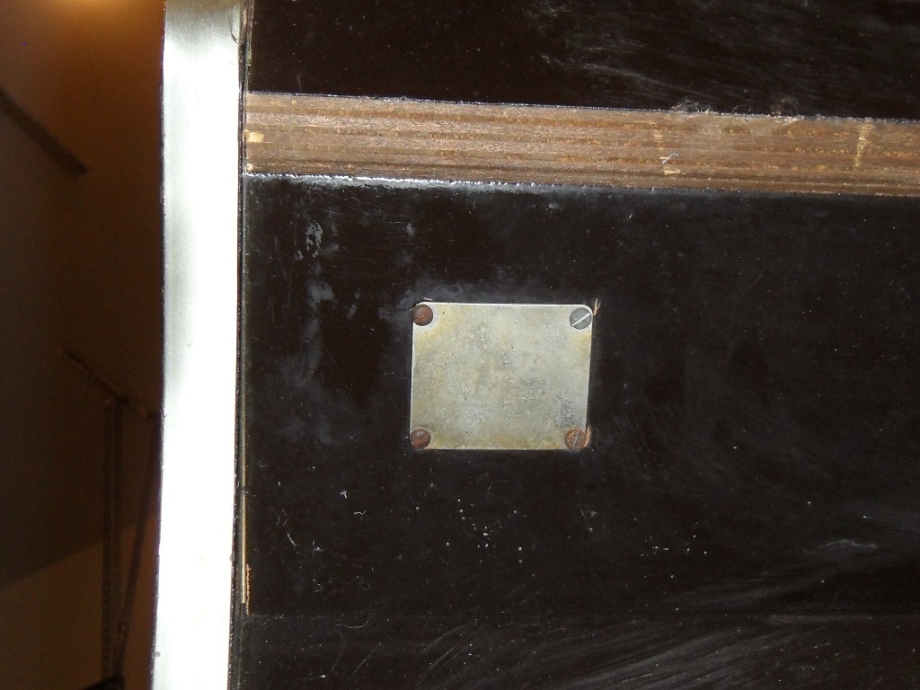
if it originaly had a proper connector or was built direct wired. Oddly there
is a metal plate over the external degauss button (still present and wired
in the cabinet but not plugged into the monitor).
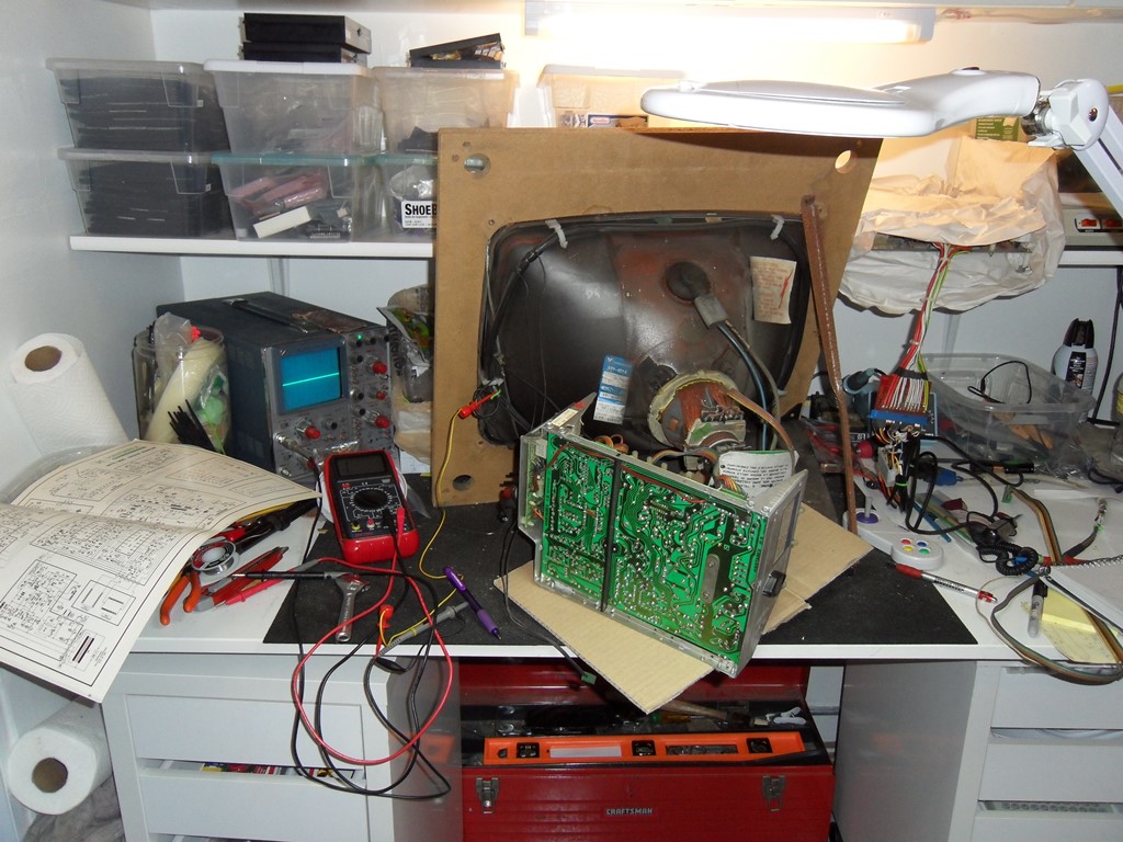
23/10/2012 - First power on
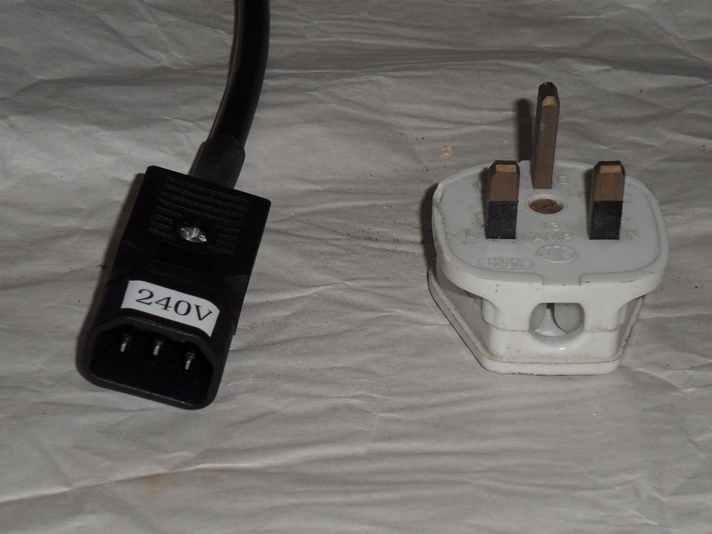
First power on with AC only gave 125V and 210V on the monitor connector (versus
spec of 128V & 220V). The marque light doesn't work and there are no coin door
lights. With the DC side on, the regulated power supplies came in at +11.97V and
+4.71V, looking reasonable. The +5V will probably go up with some light cleaning
of the connectors.
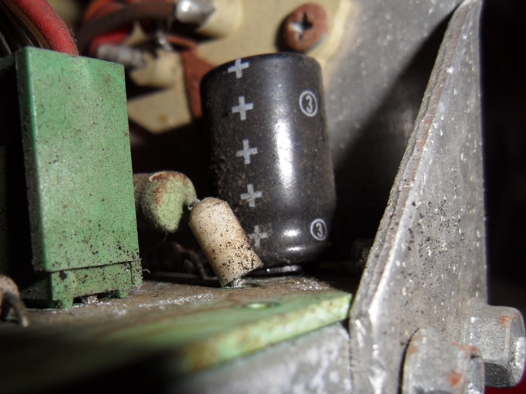
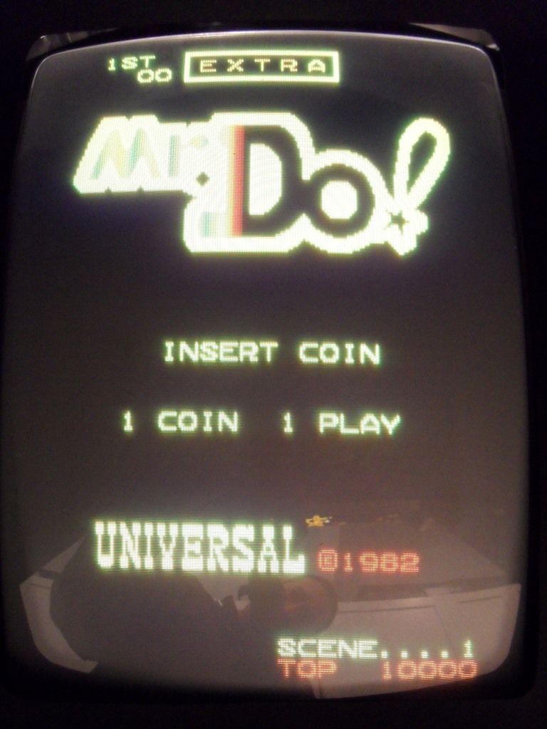
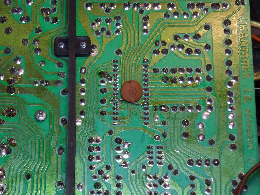
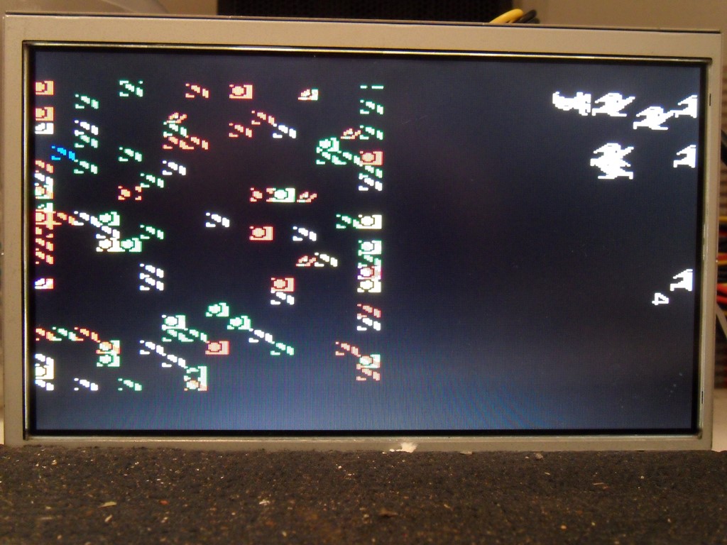
With the monitor on there was a picture of a few sprites. The game PCB doesn't
boot. After a few minutes the monitor vented an acrid smell - capacitor failure.
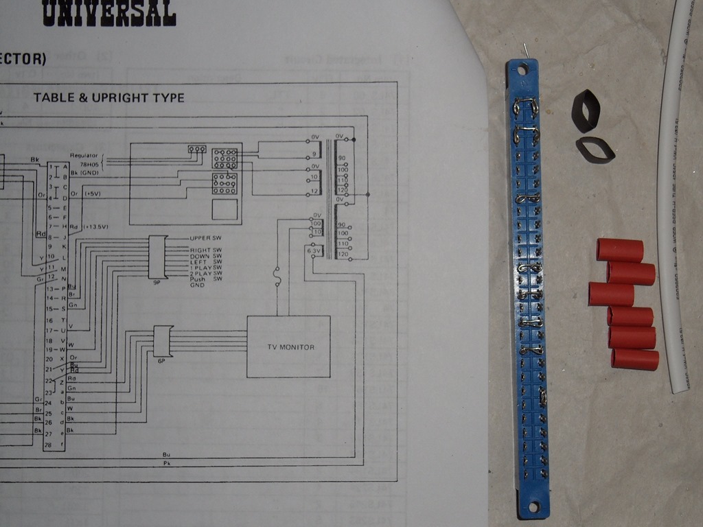
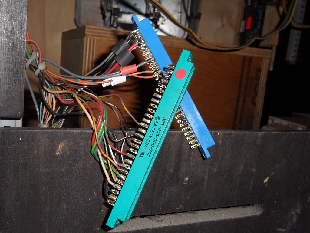
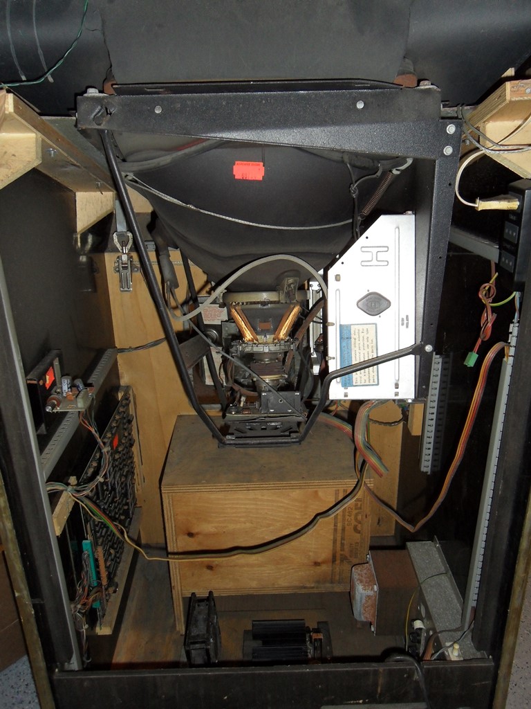
25/10/2012 - Wiring
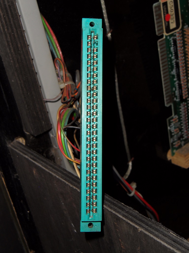
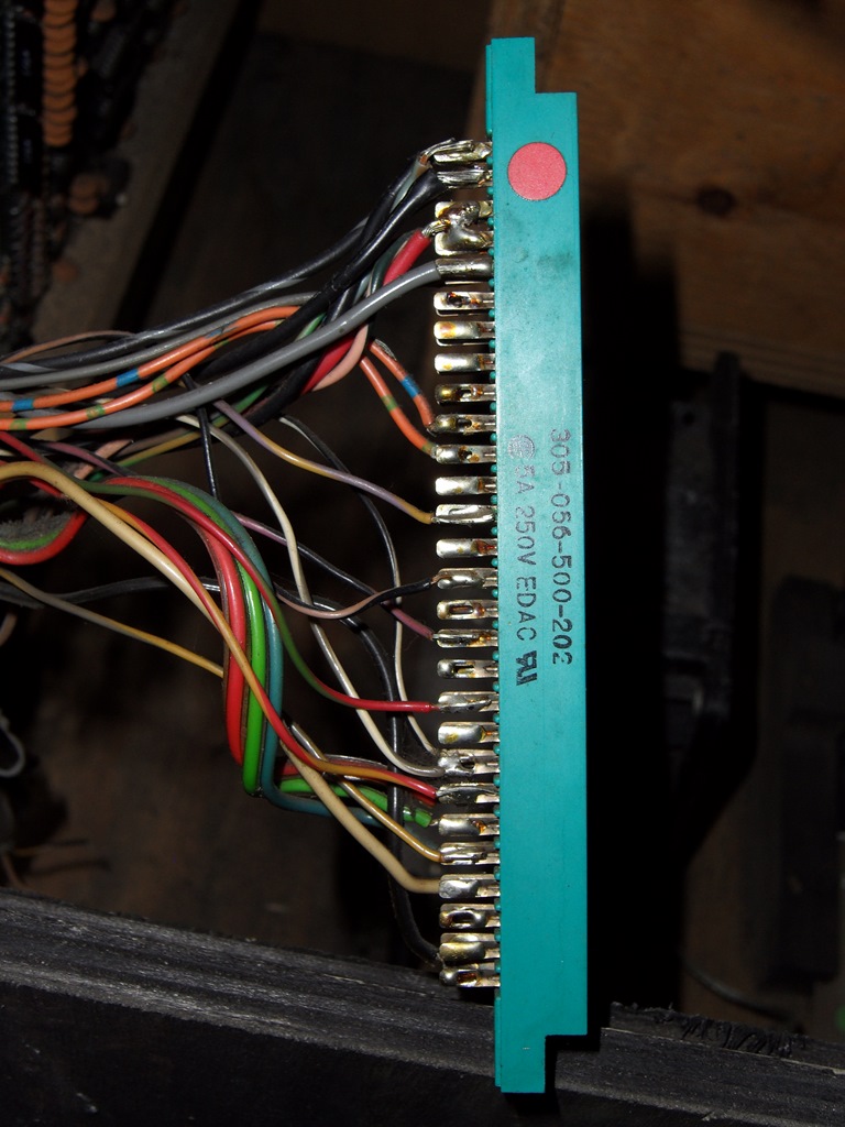
The edge connector is missing a pin (top right) and looks like it may
have been changed once already judging from the solder on the unusued eyelets
and the lack of shrink tubing. It needs replacing again I think.
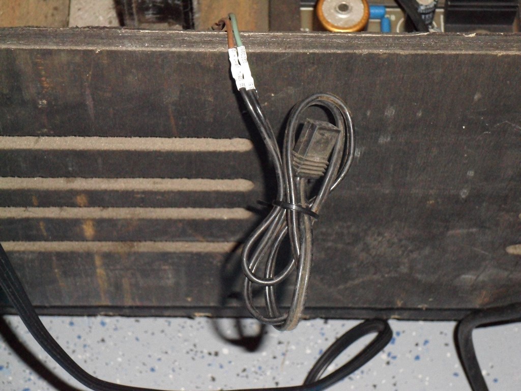
The fan has probably been replaced - it's not the metal caged one
that I usually see in Zaccaria cabinets and it's connected via a terminal
block.
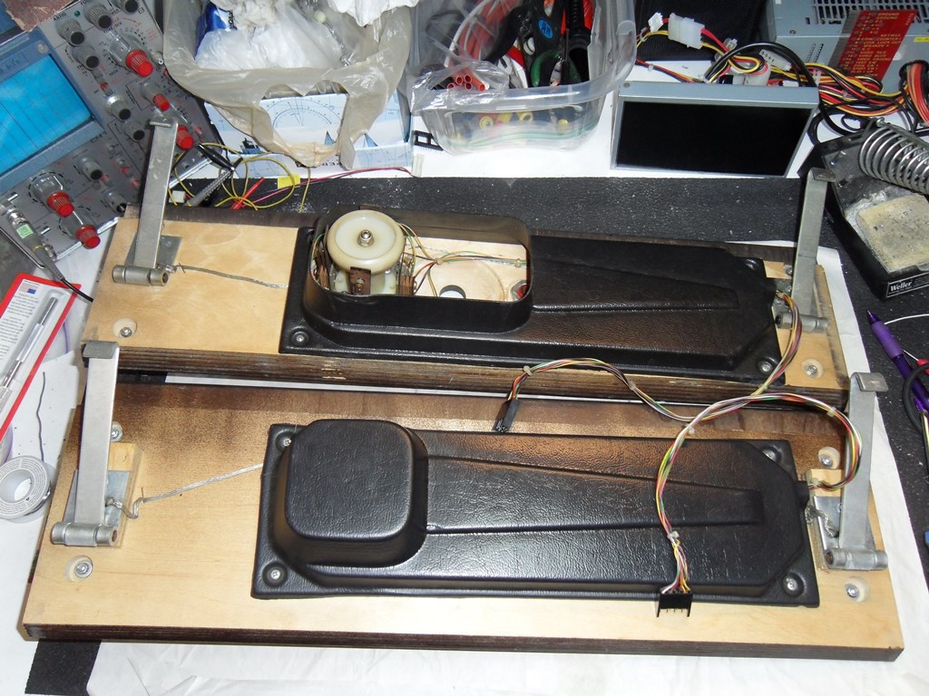
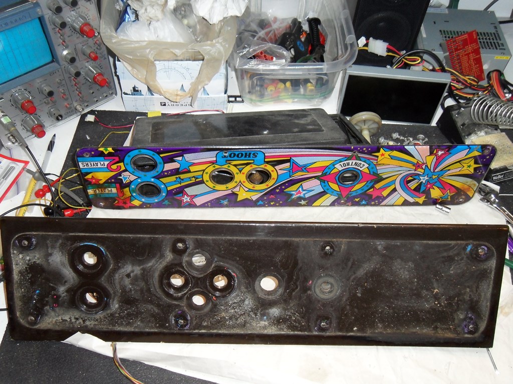
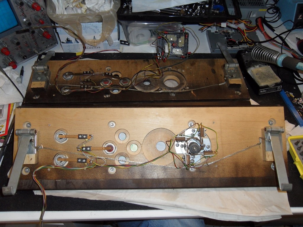
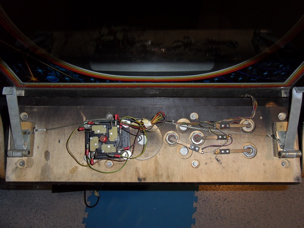
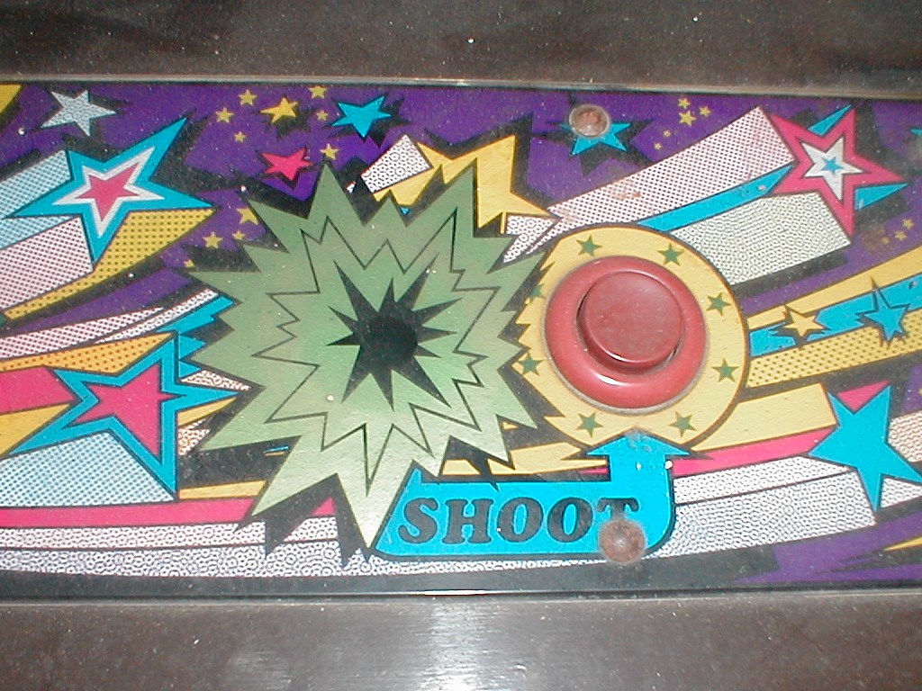
The back of the control panel shows the "modern" joystick and notes
written on the back of the wood by whoever changed it. The two shoot
buttons appear to have been wired together though it should only have
one button. I wonder if this cabinet was converted to JAMMA at some point?
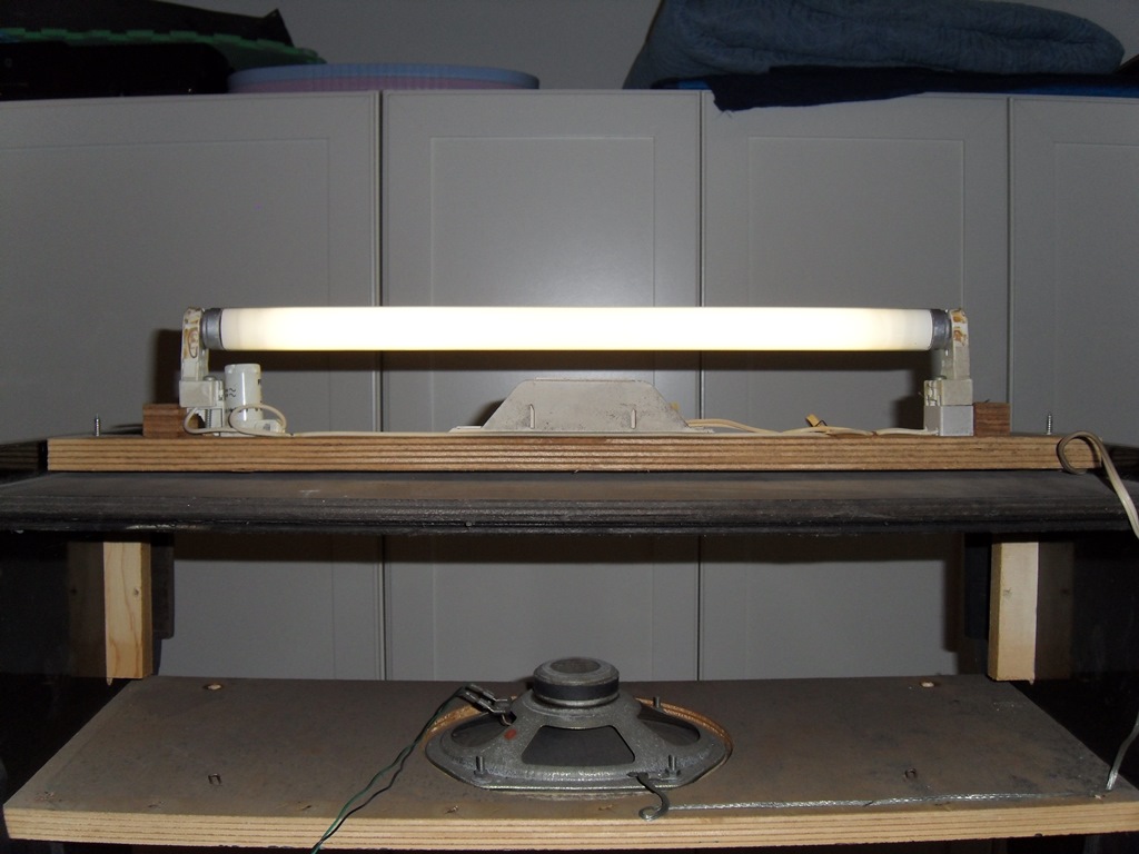
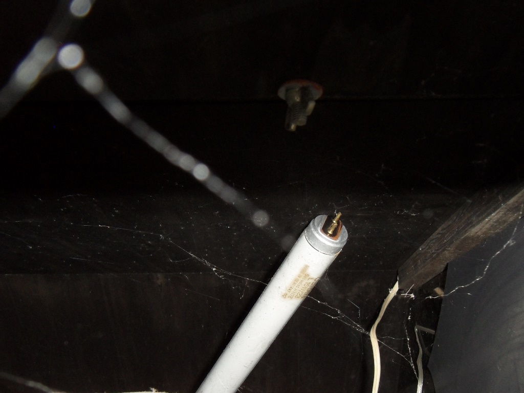
Likely reason the marque light doesn't work is because the tube is floating
around in the cavity.
Though I'm not going to reconnect the fan (I always disconnect them
because they're almost always shot and this one is no exception) I still
replaced the terminal block with a proper splice and neatly tied up the
excess cable. I also fixed the broken wire to the amplifier and secured
the cabling for it. It doesn't look like the amplifier ever had a proper
connector on it so I've left it direct wired as is for now.
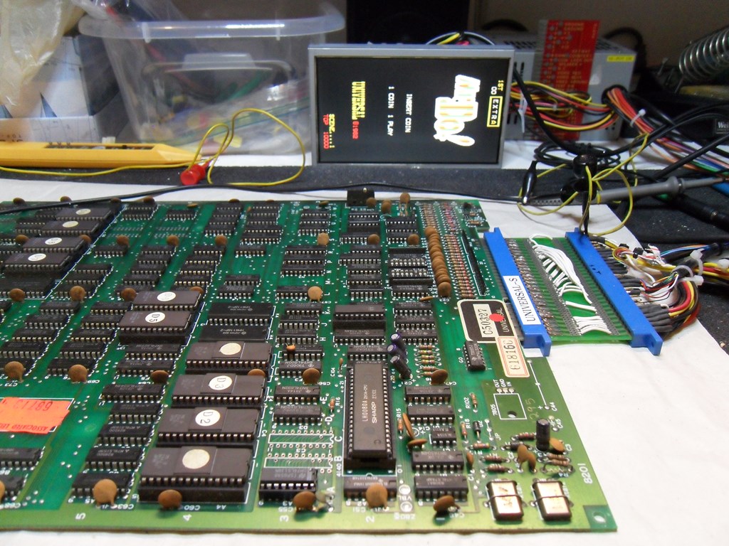
28/10/2012
Built a Universal to JAMMA adaptor for testing the game PCB on the bench.
Still no boot, pretty much the same as it was in the cab.
I went hunting around for a spare control panel with a good overlay and
joystick All I found were a couple in the same style as the current 2-button
one that's on it (both in better condition of course). Then I noticed that
the control panel on my early universal cabinet (the 2nd game I ever bought
and the 1st Zaccaria cabinet I bought that started it all)...
... that has a 1-button control panel that matches the Mr. Do! flyer.
What else do we have here? The joystick collar has "UNIVERSAL"
stamped on it :) I have no other control panels that have this type of
joystick fitted. I also noticed that the control panel wood isn't blue
so it doesn't match this blue cabinet. The "UNIVERSAL" joystick doesn't match
the Mr. Do! flyer that shows a standard Zaccaria silver rod stick but
otherwise it's a perfect match.
My take is that the flyer is an early version and the "UNIVERSAL" stick
more than likely did ship in the game.
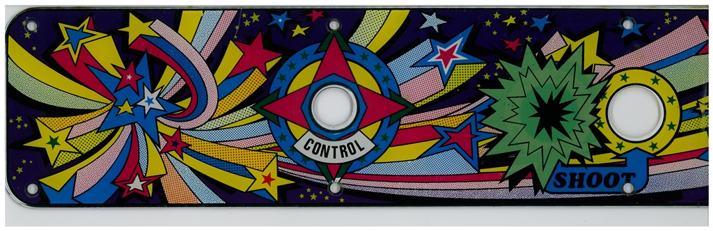
The 1-button overlay is just a slightly modified print of the 2-button
overlay but with one button covered over with a gold splat.
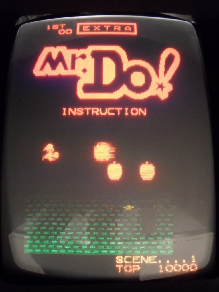
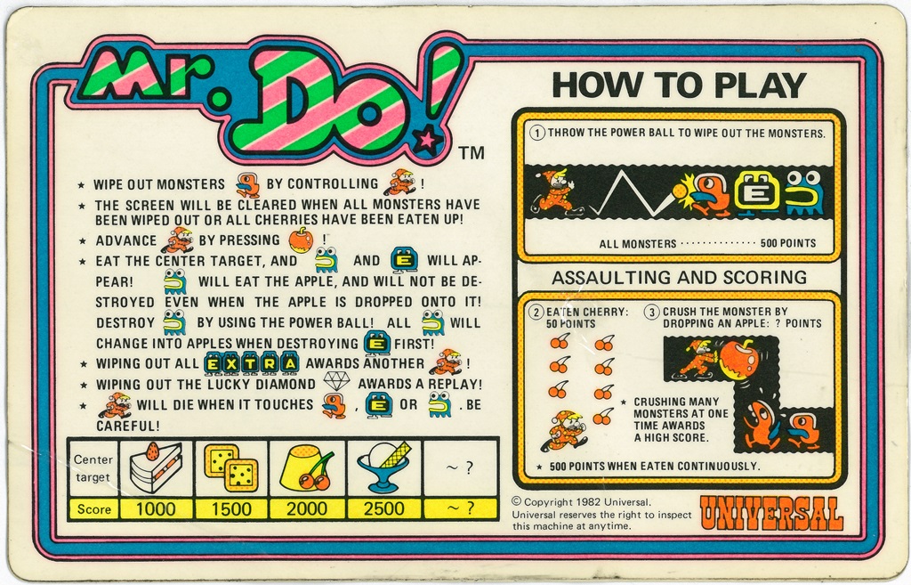
29/10/2012 - Instruction card
Scanned in a Mr. Do! instruction card I found in the bottom of the EU Money Money.
Alas, the size and style is not the same as the one on the flyer but it might be
adjustable to fit the window on the bezel until the "real" one turns up.
600 DPI Mr. Do! instruction card scan (9.9MB).
A simple cut and paste yields something that might fit when printed at the right
scaling.
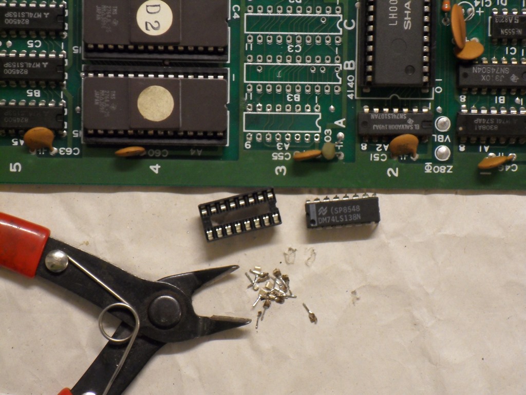
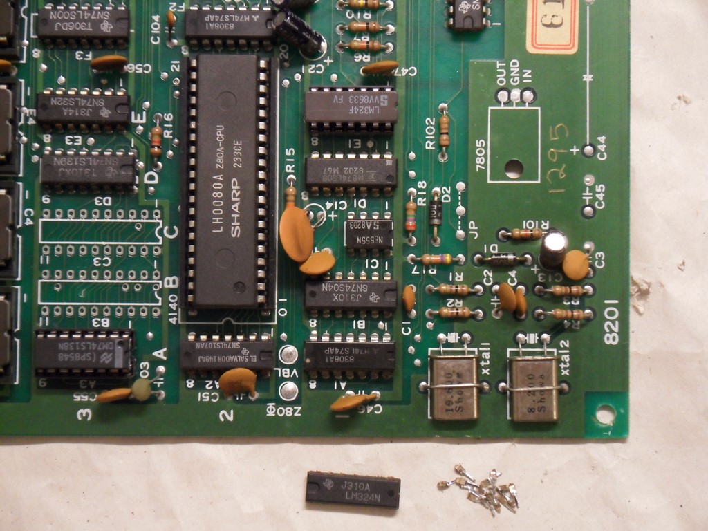
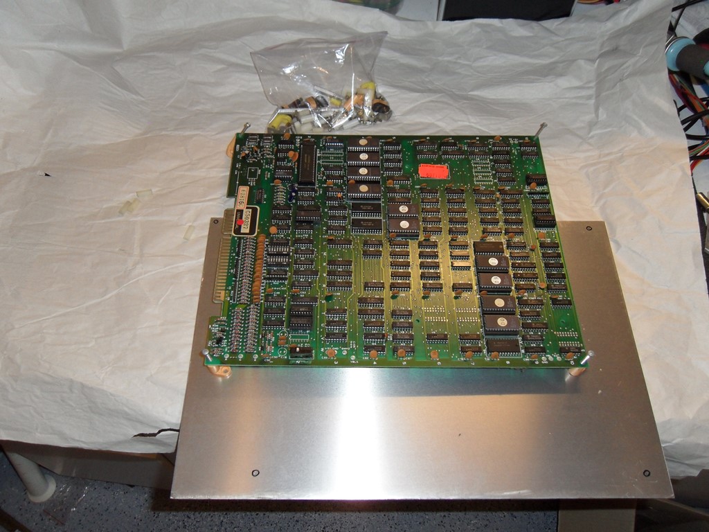
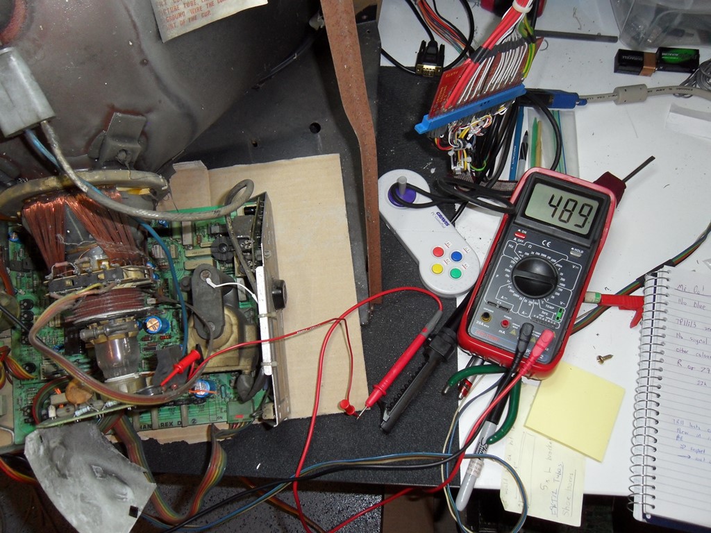
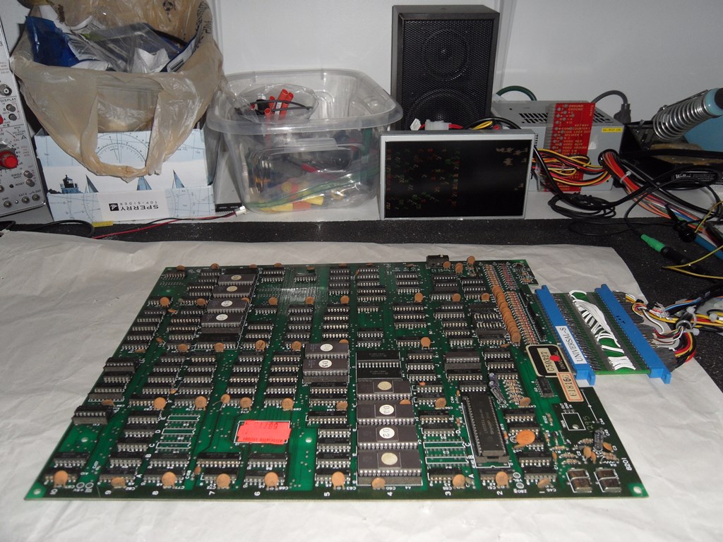
30/10/2012 - PCB work
The game doesn't appear to use a watchdog so I set up my pulse injector to
do 400pps on the Z80 reset line to keep the CPU trying to run. Looking at address
and data showed all the signals active on the Z80 but the data bus looking a bit
mushy on the scope. Moved on to see if the A/D looked OK on the EPROMS (they did) but
found pin 22 CE always low on all the EPROMS. Tracking back to the 74LS138 found
all outputs low/floating but the inputs looking OK. It was dead. Replacing it
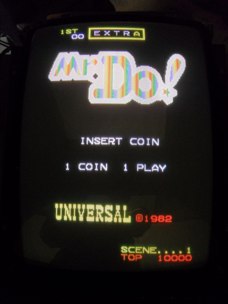
allowed the game to boot and run but with no sound. The sound is output via
an LM324 preamp. The first stage of the preamp looked OK but the last stage
had no output. Replacing it brought the sound back and it's all working now :)
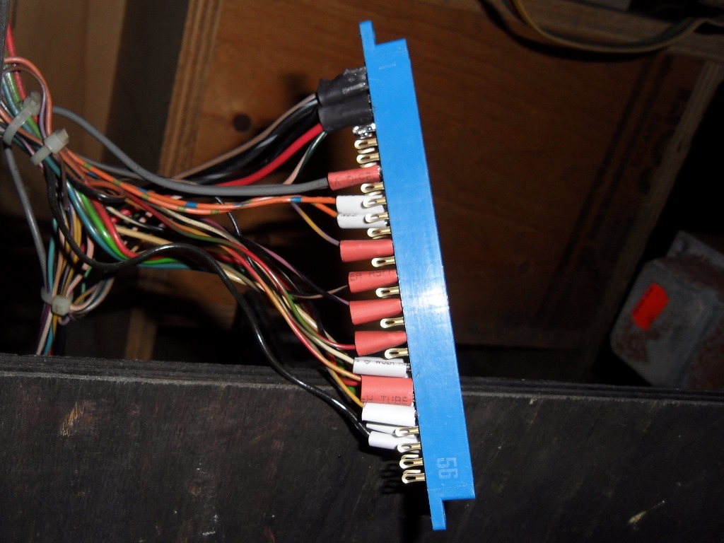
01/11/2012 - New edge connector
I put in the various links for the power and player 1 and player 2 and pre-cut
three sizes of shrink wrap (single, double link and quad link) in advance. With that
done transferring the wires from the broken connector over to the new one
was straight forward. I'll leave the shrinking for after everything is working.
The new edge connector worked fine for all controls and both players. The monitor
has problems - degauss is not working (manual or automatic), the focus is off and won't
adjust out but seems to get better as it warms up, the picture is not that bright
even with the contrast and brightness both up full and one or more caps are still
venting an acrid smell :(
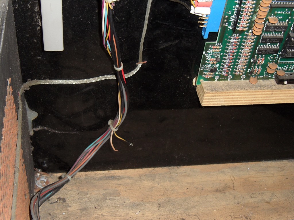
03/11/2012 - Odds and ends
There were a couple of odd wires on the wiring loom that traced back to the
control panel connector and were unusued on the control side so they just need
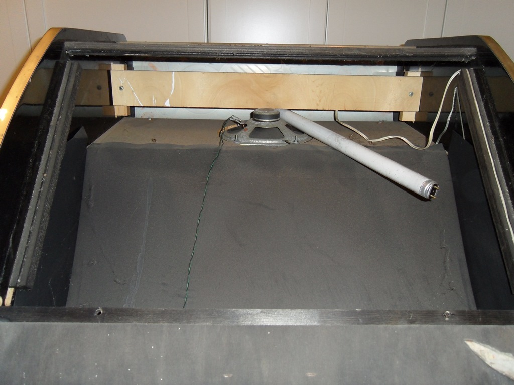
to be tidied up. Removing the access panel allowed the marque light assembly,
cardboard surround and marque to be removed. Looks the a whole new surround
is needed as the one that's in there has large tears and is missing the lower
portion. It's plain black so should be straight forward to reproduce.
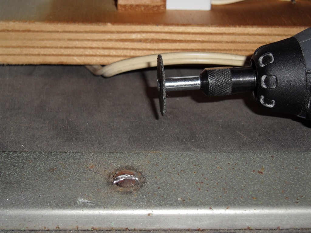
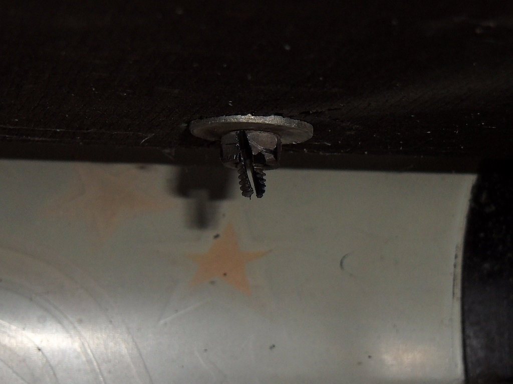
Of the six marque bolts only one was seized but it was really seized - the
usual trick of cutting a screw head didn't work so it needed the nut cutting
off. The marque light worked with the tube refitted.
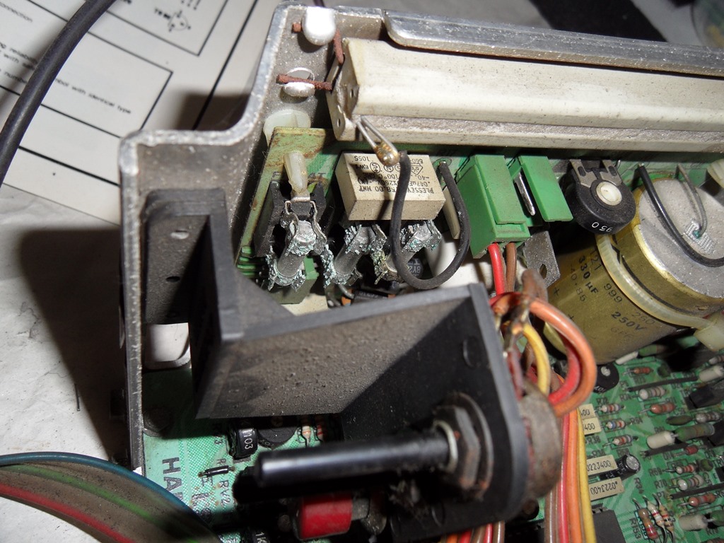
04/11/2012 - Monitor work
The monitor chassis fuses are heavily corroded and the one that protects
the degauss circuit had the wire inside corroded off so I'm hopeful this is
why the degauss isn't working (the fuse hadn't blown). The east-west PCB is
missing but I should be able to find one off a scrap chassis. The same cap
appears to have gone bad as the Zaxxon chassis so a cap kit is needed. Some
work to do.
07/11/2012 - Retest
Cap kitted, fuses & holders replaced and some other miscellaneous minor work
got a useable picture out of it. When cold the focus is way off but settles down
when when it warms up. Will leave that as is for now.
08/11/2012 - Control panel work
The 1 and 2 button overlays are indentical execpt for the gold splat
that covers the 2nd button hole. It looks like Zaccaria added the splat
layer first and then applied the remaining 2 button paint layers on top
- up close the 2nd button artwork can be faintly seen underneath the
gold splat.
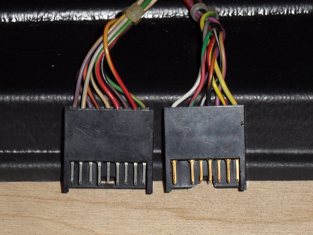
One other variation I didn't notice before is that the two control panels
have different wiring connectors. The right Mr. Do! control panel I found
on my other cabinet has the wrong connector for this Mr. Do! cabs wiring :(
This spare control panel I found from a mini cabinet will donate it's
overlay and joystick to replace the ones on the universal.
The universal overlay and joystick will go on the Mr. Do! cabinet.
The overlay has some serious cig burn that I tried to polish out. It's
still not great but better than it was.
09/11/2012 - Artwork scanning
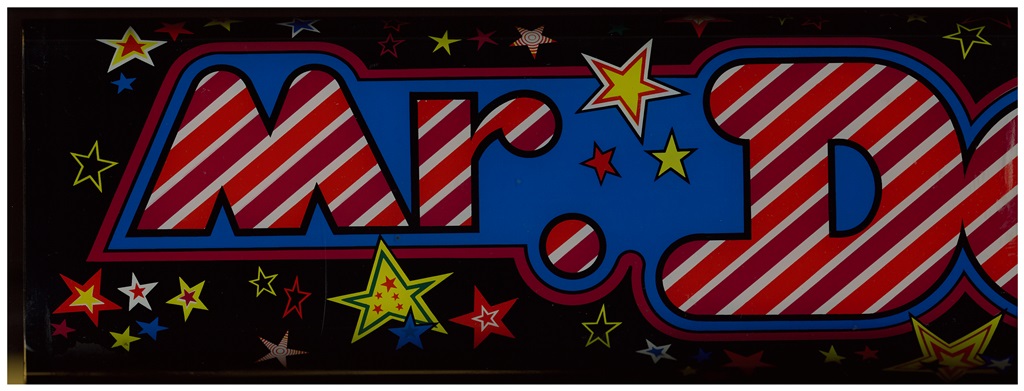
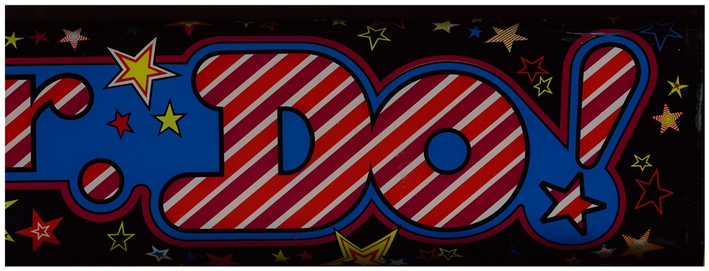
Scanned in the Mr. Do! marque - the archive includes the curved over portion.
400 DPI Mr. Do! marque scan (28.0MB).
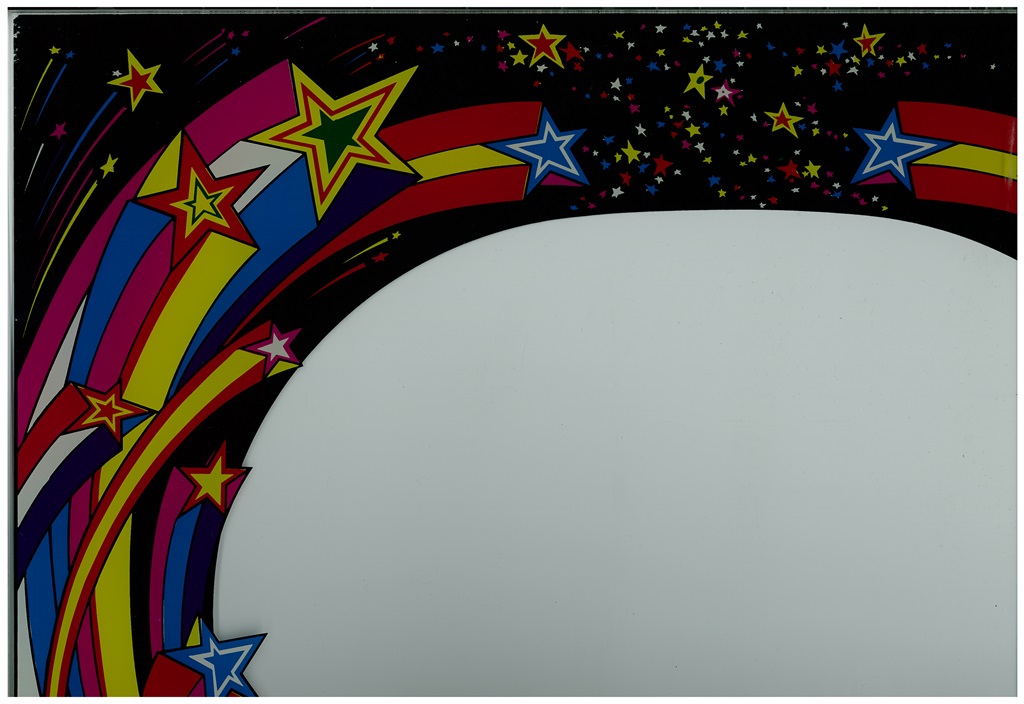
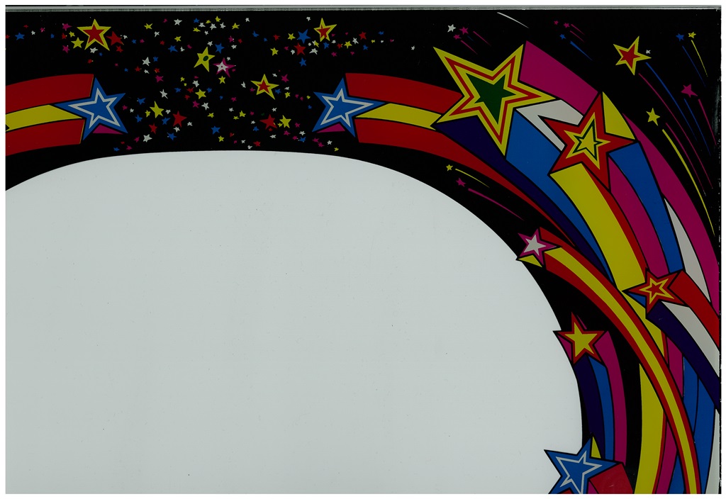
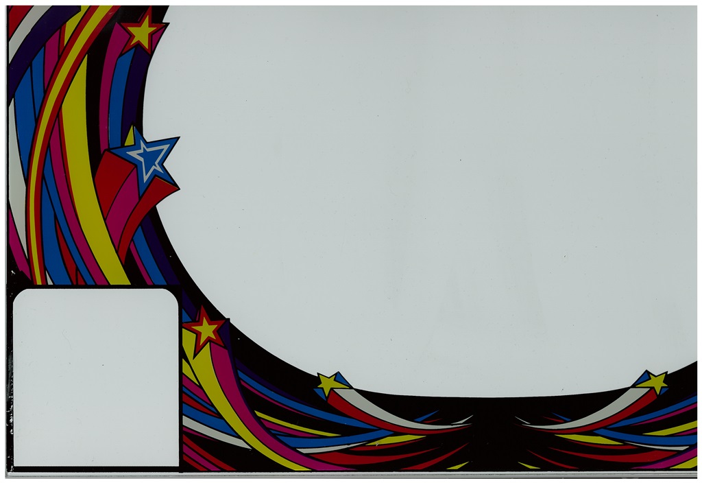
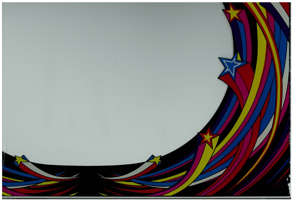
Scanned in the universal monitor glass.
300 DPI Universal monitor glass scan (14.8MB).
Scanned in the Mr. Do! control panel overlay (1 button).
400 DPI Mr. Do! control panel overlay scan (11.7MB).
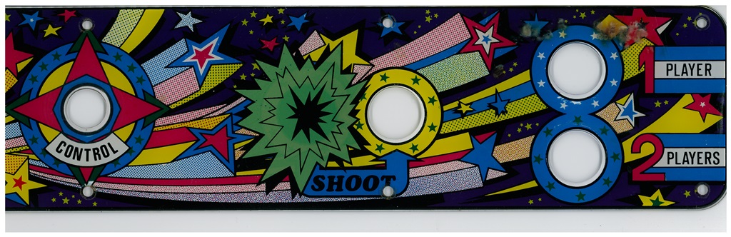
Scanned in the universal control panel overlay (2-button).
400 DPI Universal control panel overlay scan (12.9MB).
20/11/2012 - Control panel work
The existing control panel has the joystick hole drilled out to make it bigger
however the original joystick still fits. The overlay and Universal joystick collar
cover the hole nicely.
The donor control panel is fitted with a spare two button overlay and standard
chrome shaft joystick so it can go back in the cab it came from (it'll need a blanking
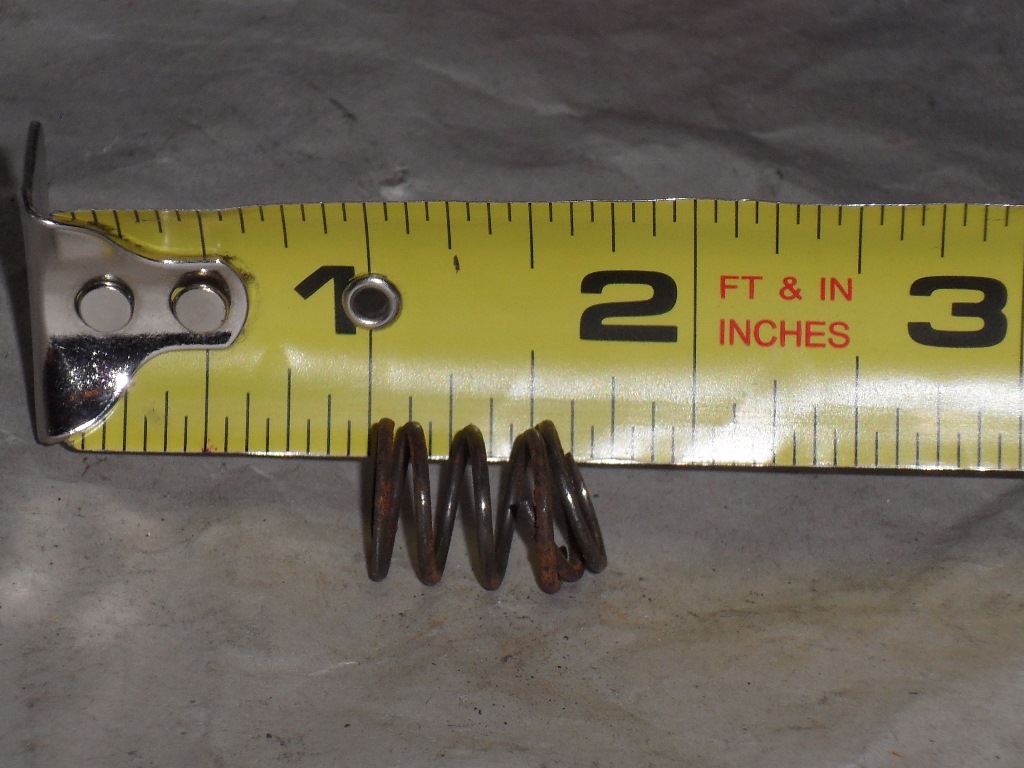
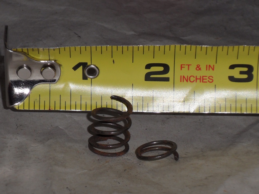
button in the hole as it's only wired for a single button). The spare joystick has
a broken spring that I need to find a replacement of.
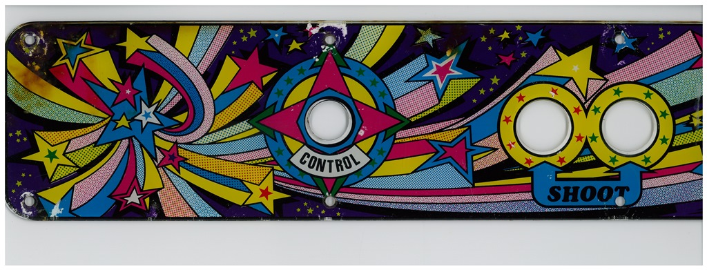
The restored control panel fitted :)
29/11/2012 - PCB mounting plate
The cabs is missing it's orginal PCB mounting plate so I ordered some replacements
based on the scans of the Super Cobra plate I took a few weeks ago fron OnlineMetals.com.
I ordered 16.875" x 11.4375" in 6061-T6 aluminium, 0.9" thick that fit OK but I'd go
with 0.75" next time.
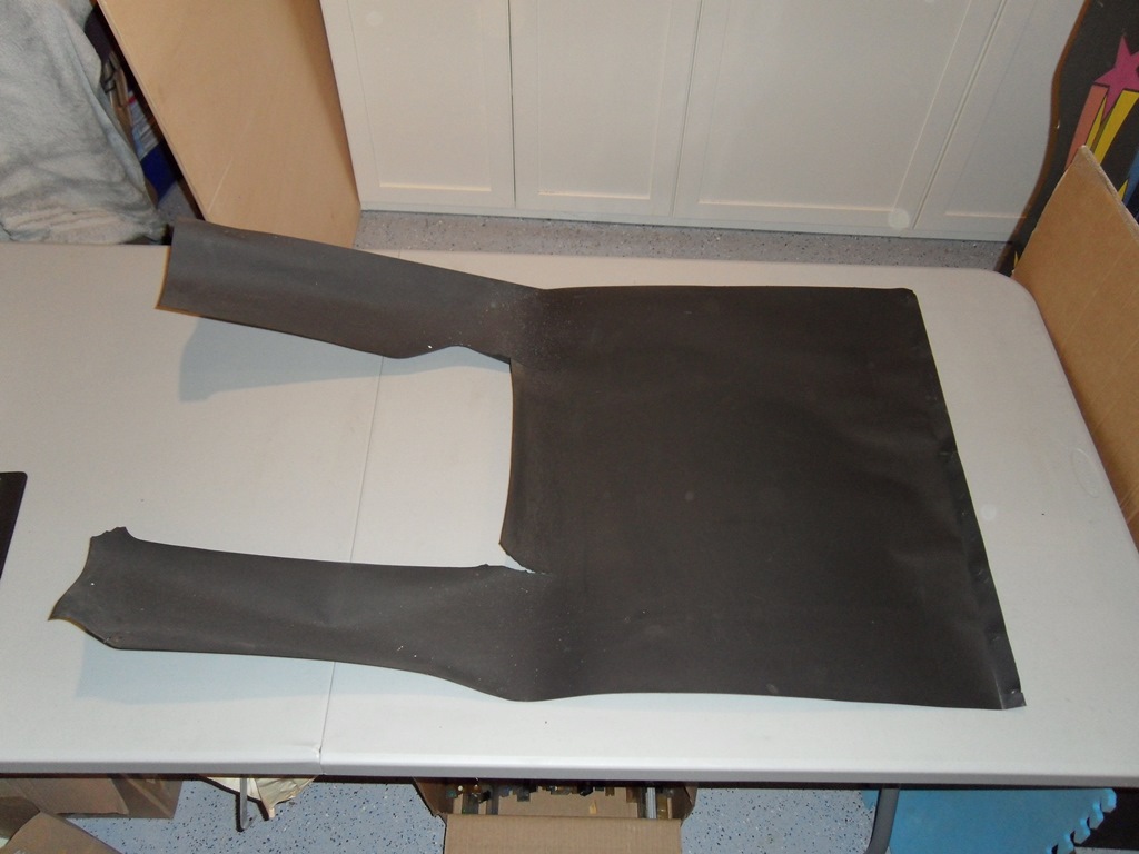
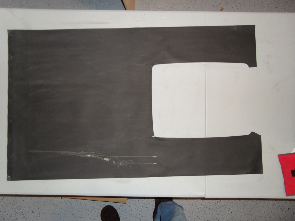
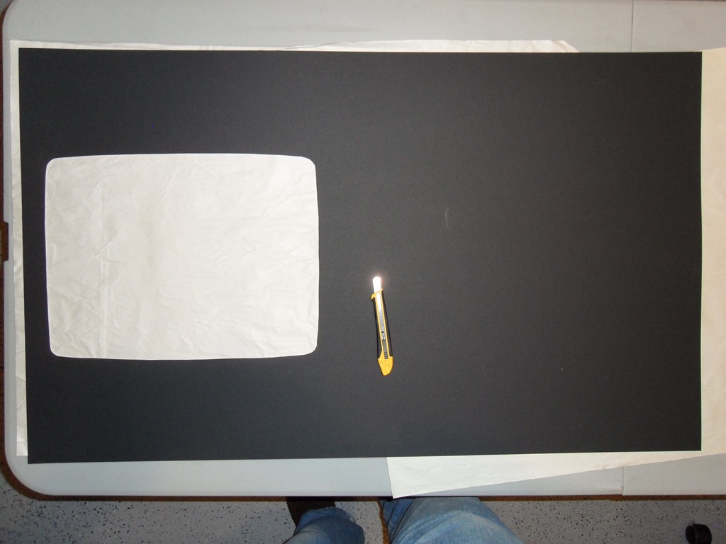
30/11/2012 - Cardboard surround
The surround in the cab is torn and missing the bottom piece so I decided
to try to repro a new surround for it. I found a thicker "4-ply" cardboard sheet
at Ben Franklin that they cut to the correct size (23 5/8" x 39") in the framing department. I used
the original surround as a template to mark the monitor cut out. Despite my very poor
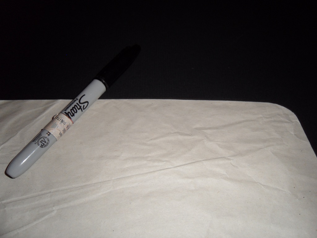
art skills the monitor cut out ended up not too bad. With a card being white with black
laminate I needed to use a black Sharpie to make the edge of the cut out black.
Pretty happy with the way it turned out but...
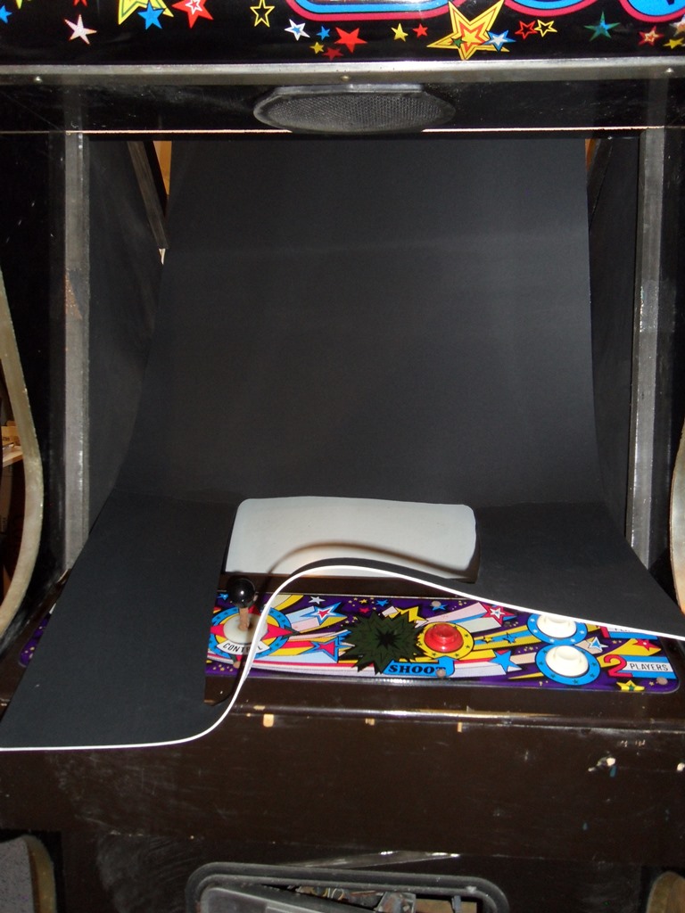
The card was too thick to be able to easily manipulate it back in the cab and the
back curve was too sharp for it so it ended up creasing :( Tried taking it out, flattening
and reinforcing it for a second attempt and it still creased in a different place :(
Decided to leave as is for now as a an experiment with lessons learned.
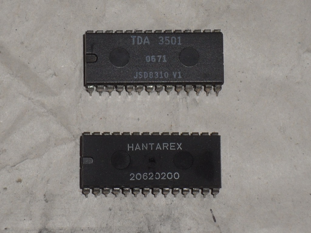
04/12/2012 - Monitor troubles
The green on the monitor had some intermittant brightness issue and
then lost blue completely :( Replaced the colour pre-amplifier IC
socket (that looked like it was the cause) and the colour pre-amplifier
itself but it made no difference to either issue :( Leaving it for now
as I need to build a monitor test fixture to fault find it on the bench.
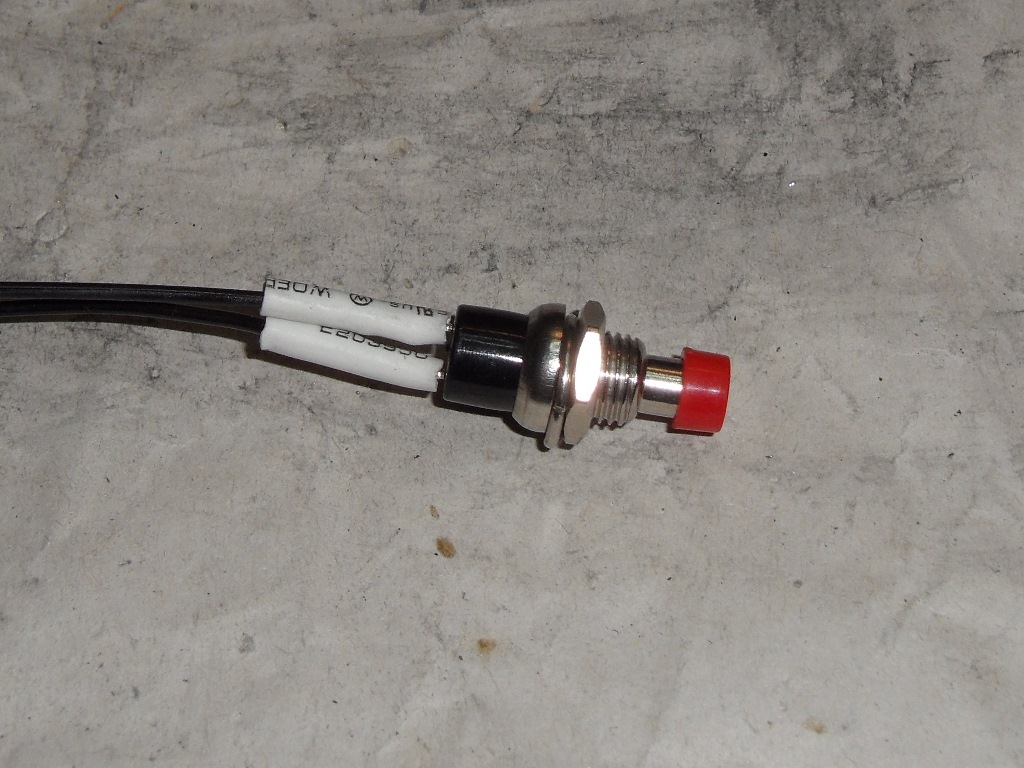
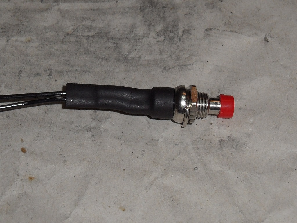
06/12/2012 - Credit button
Finally remembered to order some push buttons to use as credit switches.
Simple to make and fit in the coin slot.
07/12/2012 - Instruction sheet
Printed out three sizes of the instruction sheet I made above and picked
a winner. I used a tiny dot of glue in each corner on the plain area to hold
the sheet in place. I forgot to account for the control panel obscuring the
bottom of the glass - another lession learned.
08/12/2012 - Finshed for now
It's all done for now except for the monitor issue that I'll come back to
once I have a test setup in place to work on them.
11/12/2012 - Monitor test rig
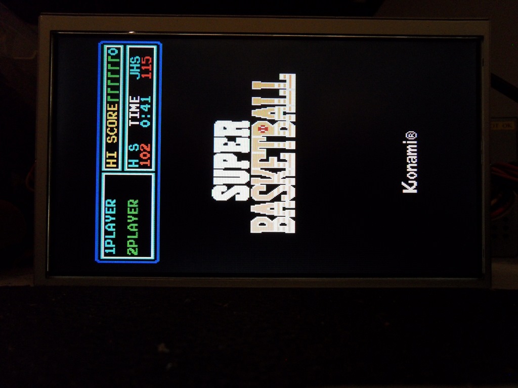
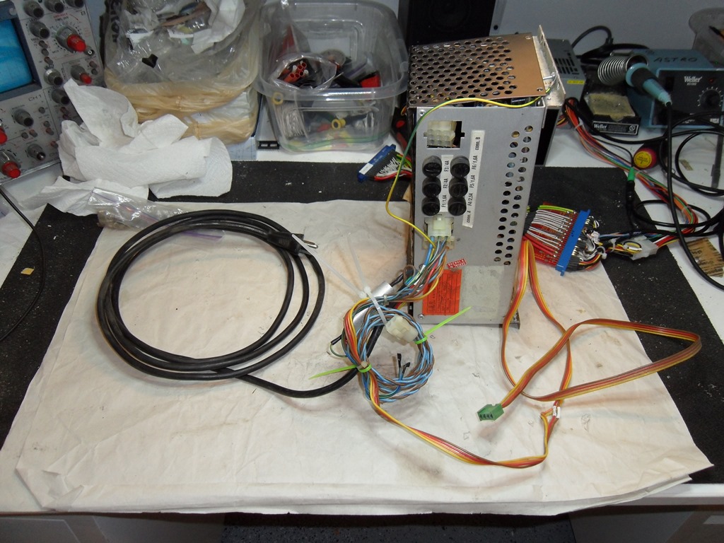
I needed a game PCB to use as a video signal so I followed the the rule of
old game boards - if the game is poop it'll work perfectly. No exception to the
rule here, the Konami Super Basketball worked fine :) The IGR EU power supply
from the old EU Money Money provides the dual power for Hantarex monitors. The
video cable from the same cab spliced into the 15-D (VGA) I use on my test rig.
All set.
13/12/2012 - Monitor test rig part 2
Found a dusty old monitor in a none-standard frame (thus not easily reused)
as a suitable tube to run chassis on the bench for testing. Didn't expect the chassis
on it to be working but it came up and tweaked to a very nice picture. Spare working
chassis are always useful. Next is to fix the Mr. Do! chassis.
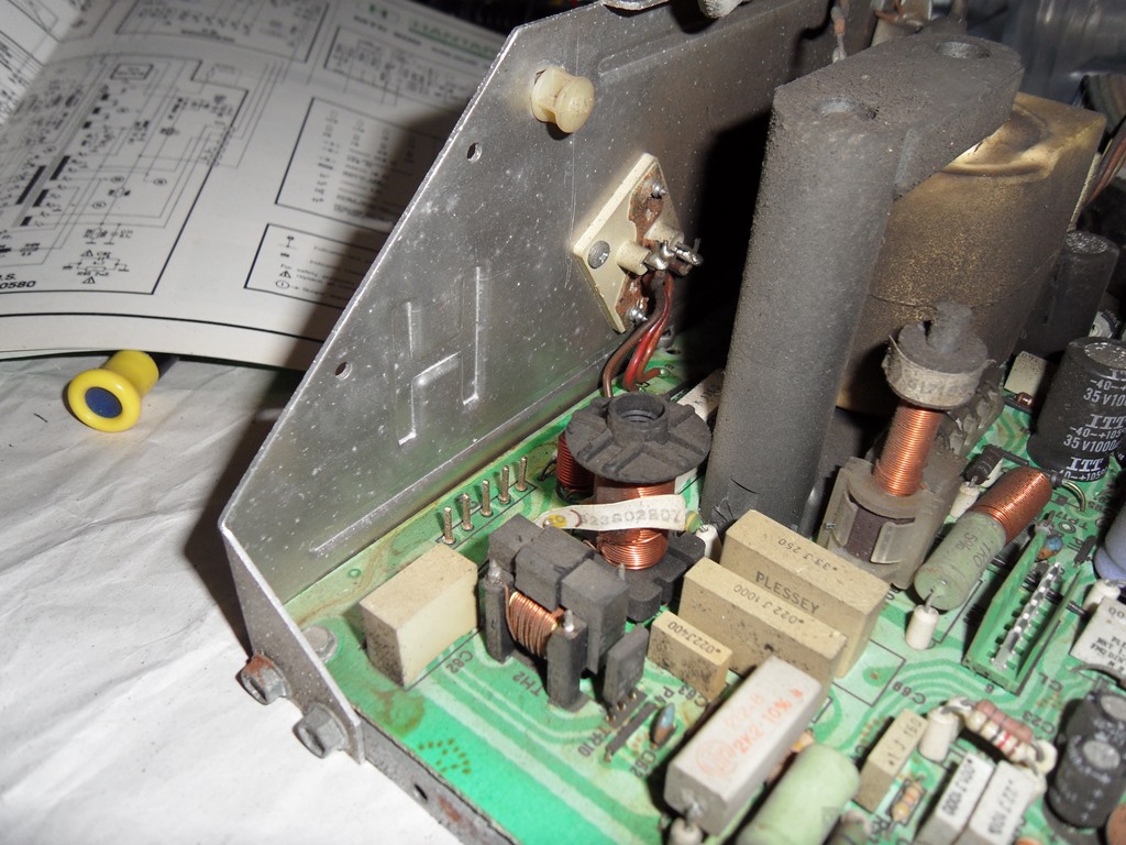
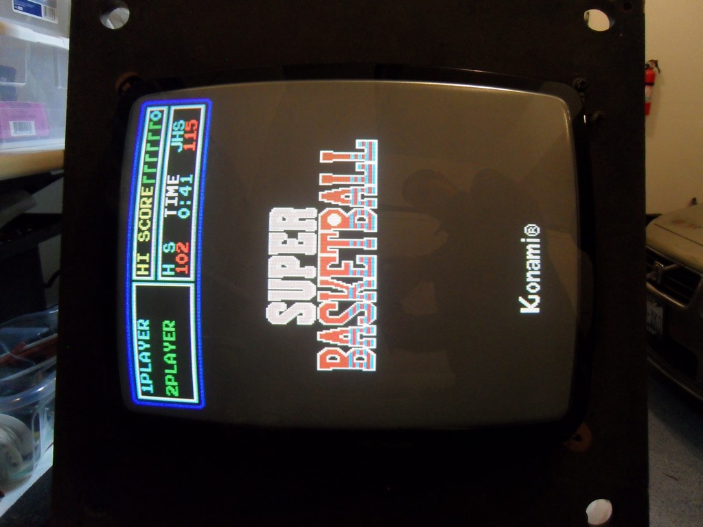
03/01/2013 - Monitor test rig part 2
The Mr. Do! chassis had two issues - the first was that the picture was out of
focus on initial power on. The second was that there was no blue.
Already swapped the RGB preamplifer socket and the amp itself so I knew those were
OK. The whole lot just squeezed onto my bench to be able to poke around
with a scope. No signal on R79 out of the preamp. Using the diode check on the
multimeter indicated a fault accross BE of TR11. Took at stab at TR11 (BF871) first
but was wrong. Turned out it was D18 (1N4148) that was bad and replacing it brought blue back.
The focus issue was clearly a measurable drift in the focus voltage as something warmed -
these sort ot warm up focus issues have often been a bad LOPT in the past but since
replacement LOPT's for the MTC-900 series are no longer available it can wait for final
failure.
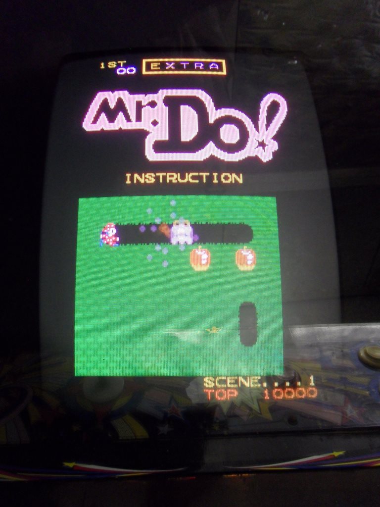
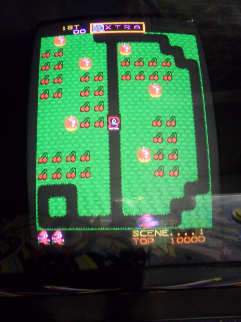
06/01/2013 - Done!
With the monitor chassis back in the cab the picture looked very good after
10 minutes of warm up time.
Mr. Do! Maintenance 2013
Mr. Do! Maintenance 2015
Mr. Do! Maintenance 2017
Mr. Do! Maintenance 2019
Mr. Do! Maintenance 2021
Mr. Do! Maintenance 2022
prswan@gmail.com


 w/Mr. Do! instruction card (edited).JPG)