
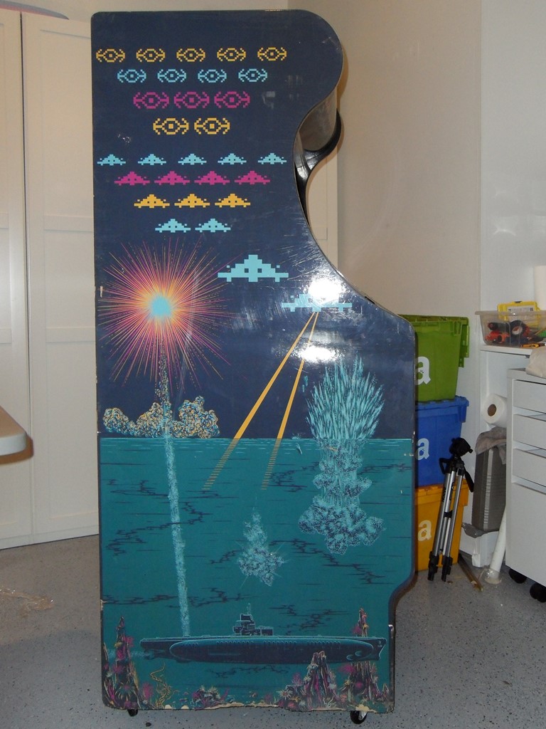
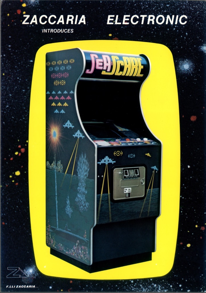
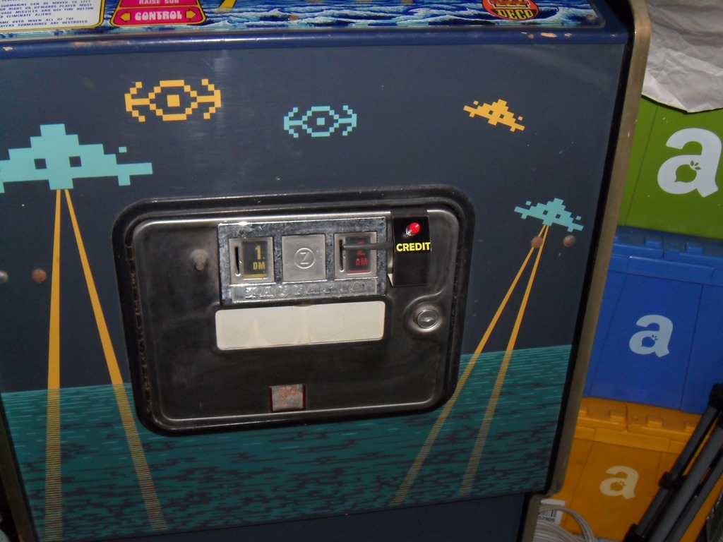
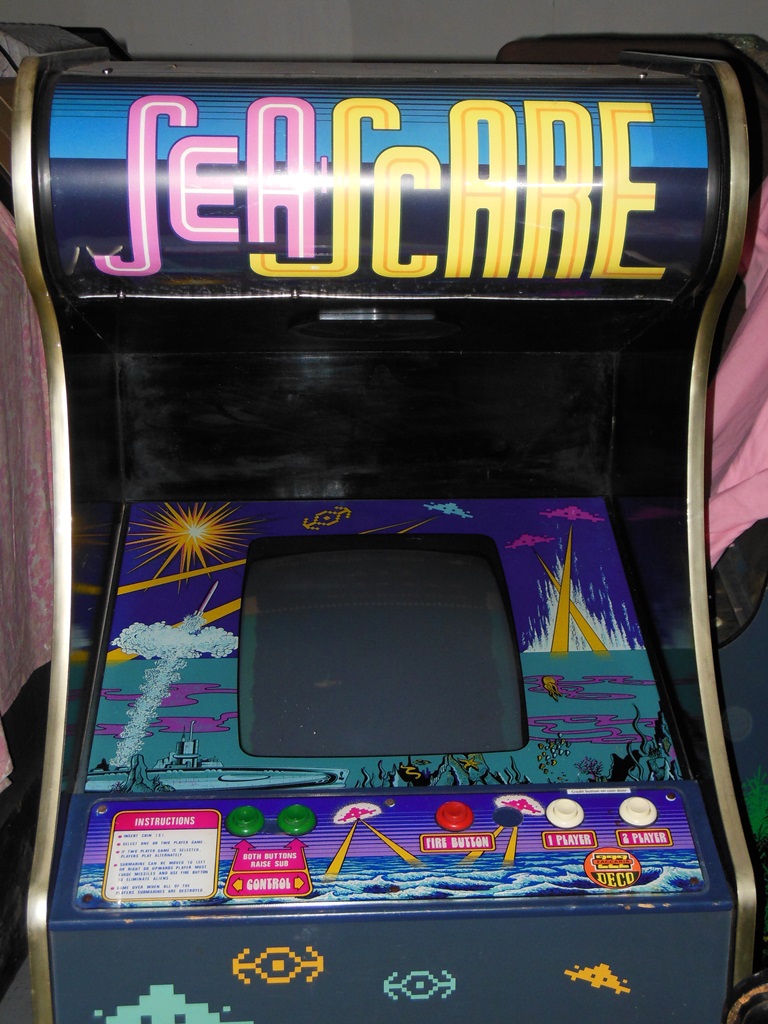
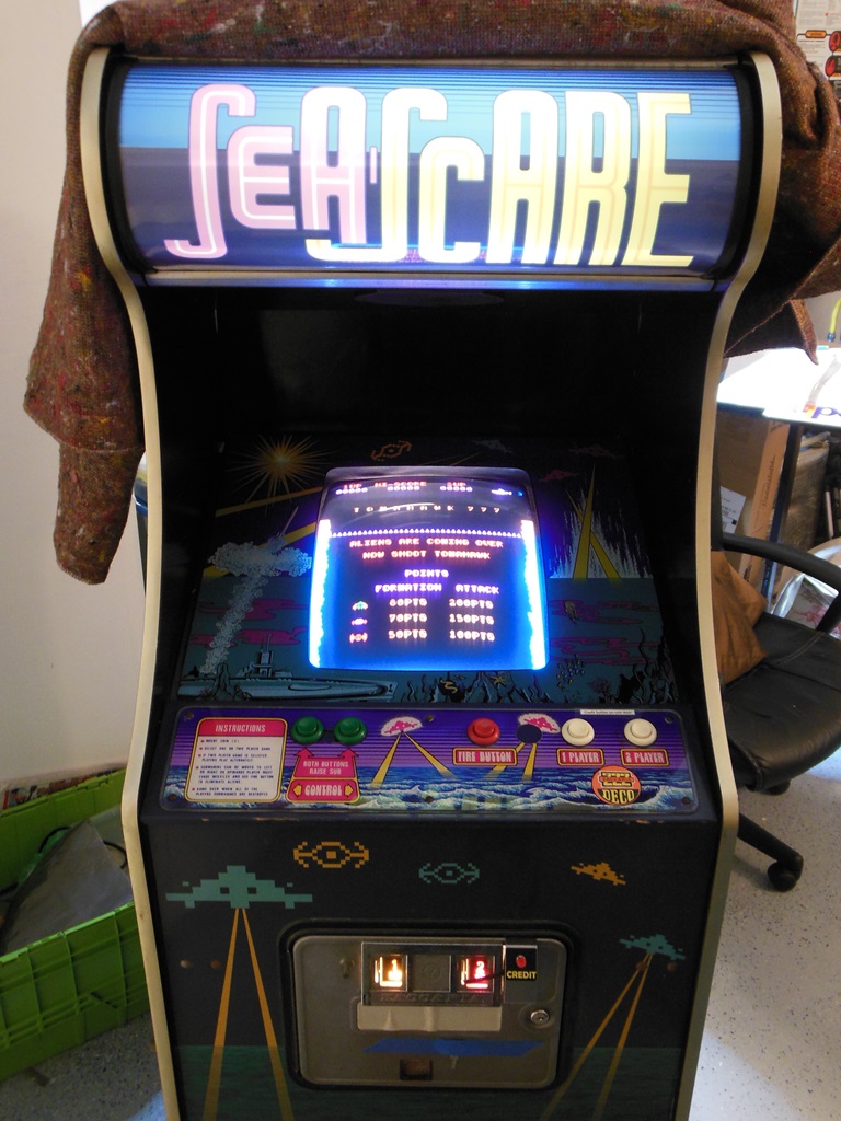
Spotted this cabinet in an auction and noticed it was a Zac in the same format as Galaxia/Astro Wars. I've never seen one before or since this one and no flyer has been found for it. Originally, I thought it was a Space Firebird converison from something - based on the art theme and the prior association with Data East for Astro Wars I guessed that it might have been a version Tomahawk 777. Did it have a Zaccaria name? Did it use the same Zaccaria hardware as Astro Wars rather than the native Data East hardware?
|
|
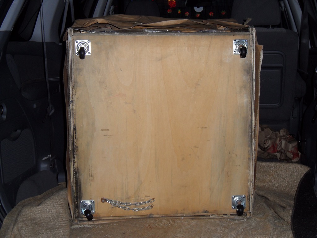
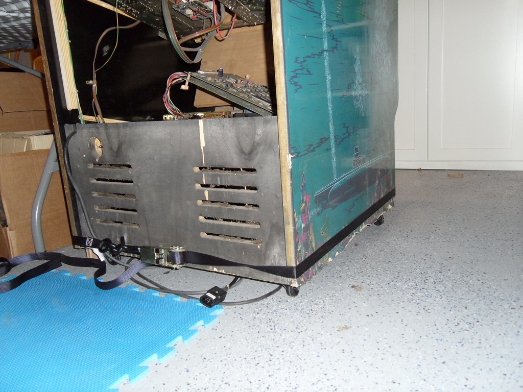
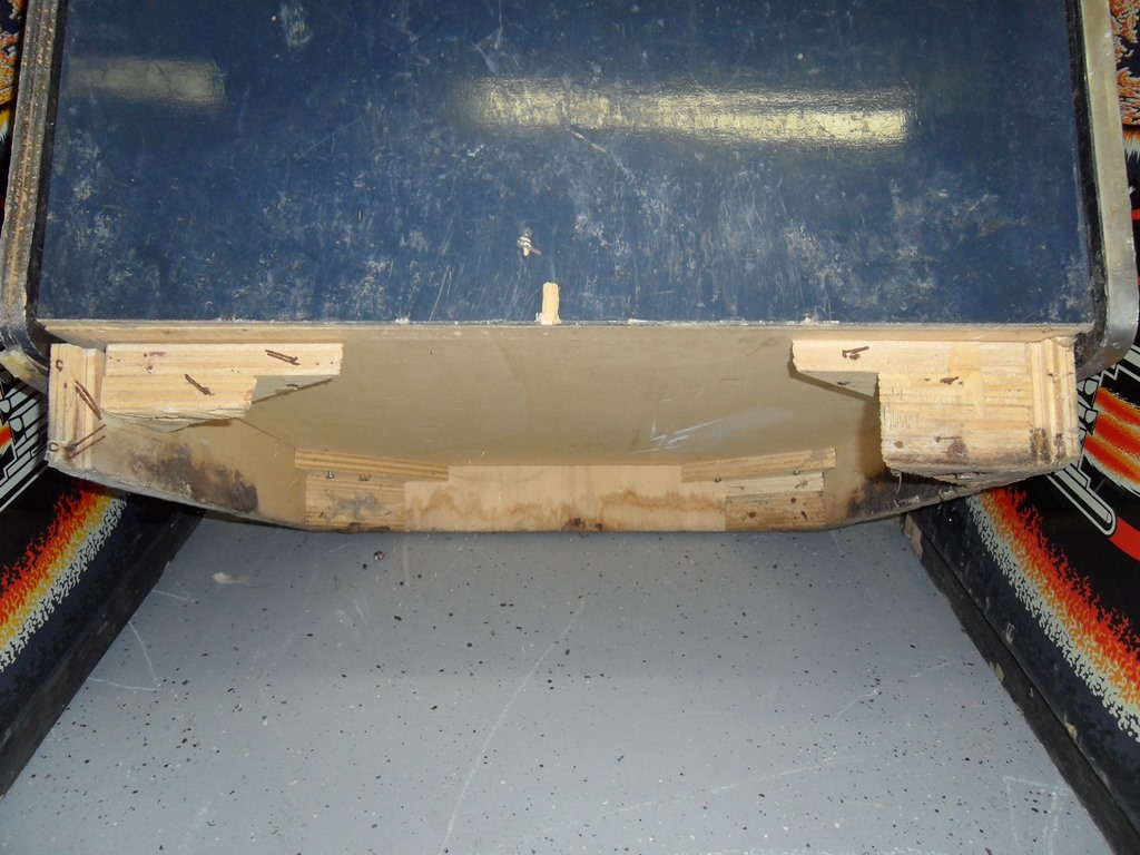
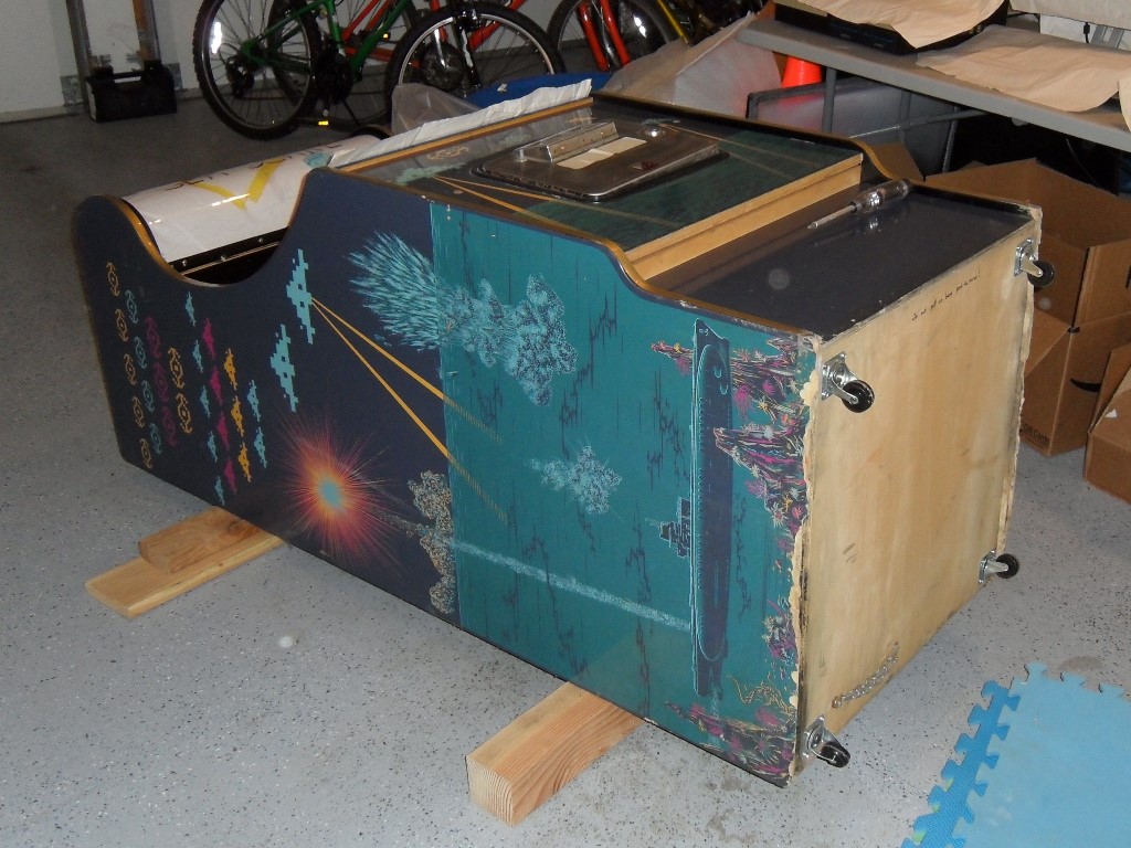
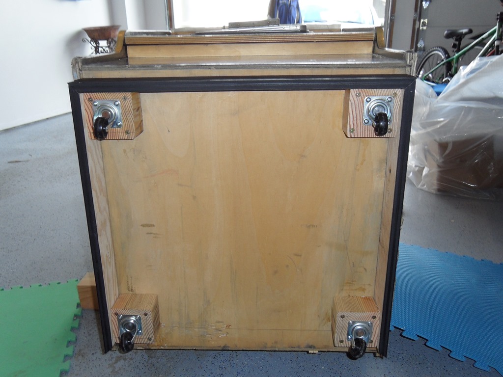
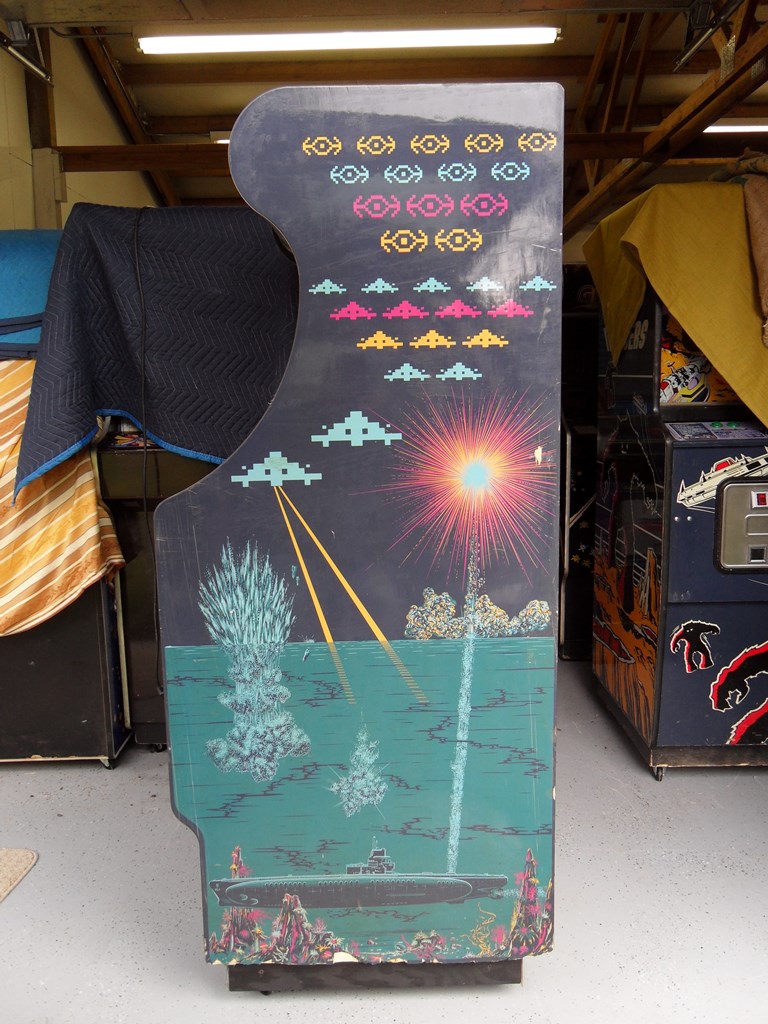
The cabinet was shipped to me with no base and just resting on the side panels. As a result, the bottom of the side panels are baddly chipped and the base is starting to separate. There's no sign of any screws or holes for feet or a usual base so I'm not sure what the bottom should be like. I'll have to check an Astro Wars. For now it's castored to get it off the ground.
|
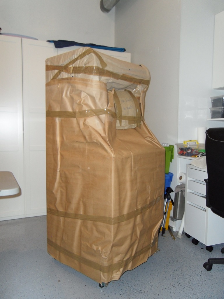
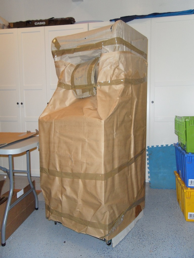
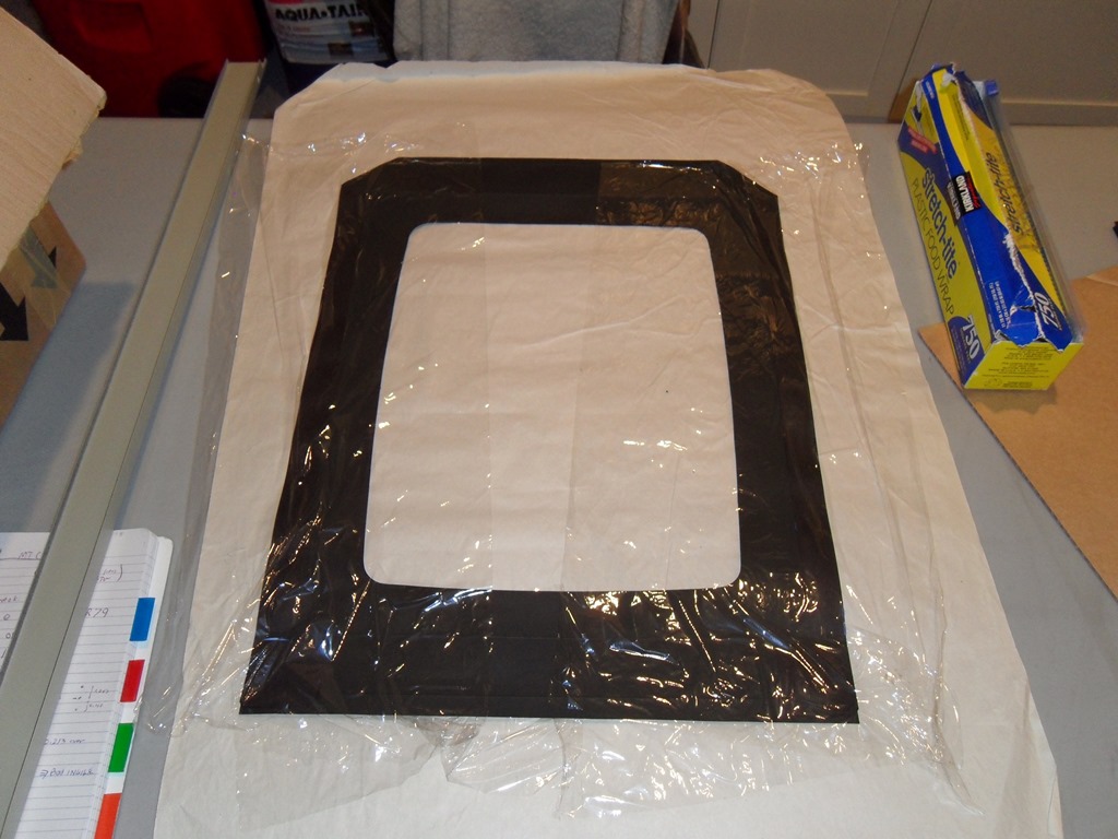
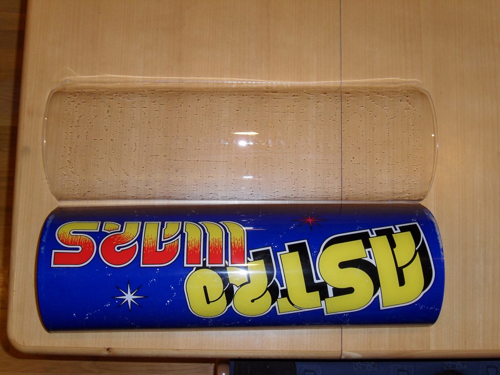
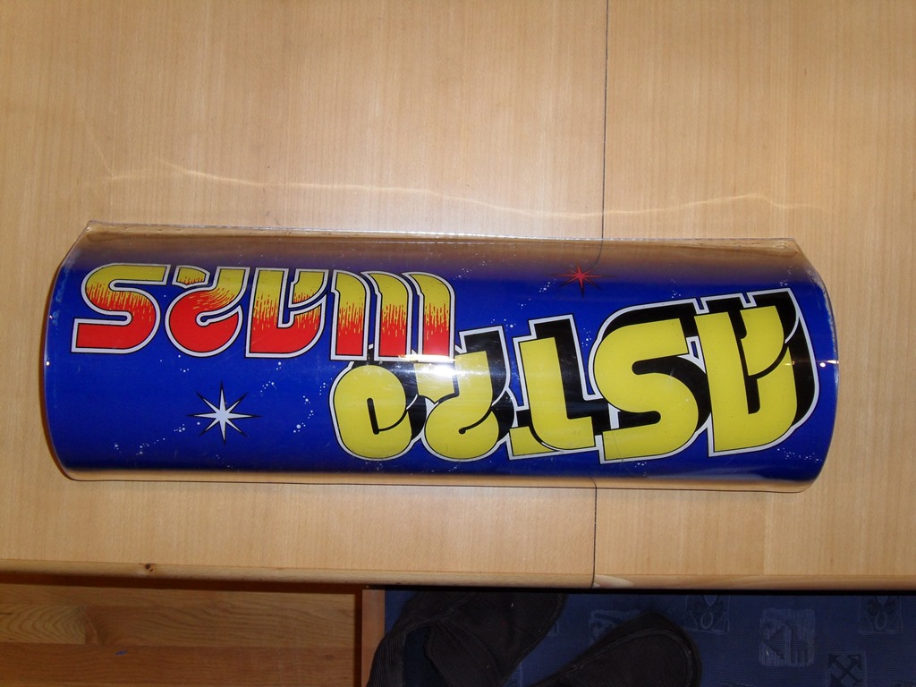
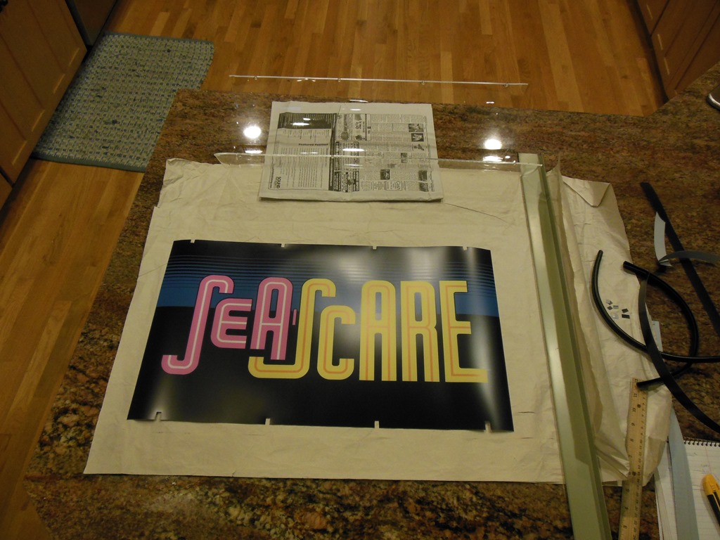
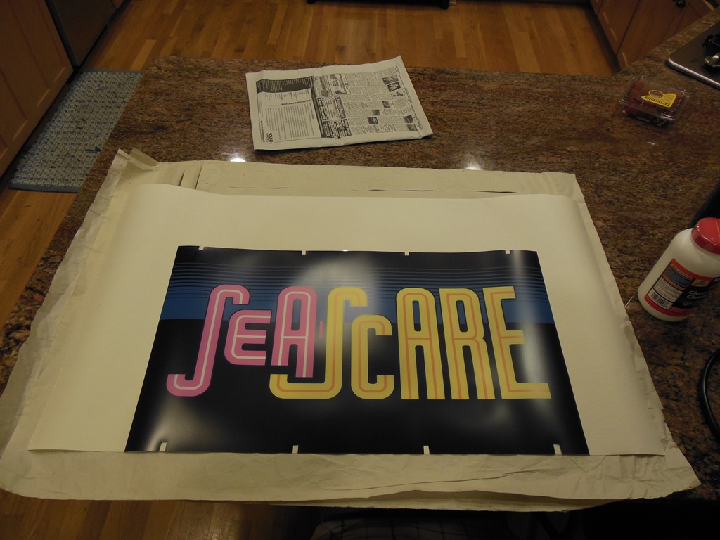
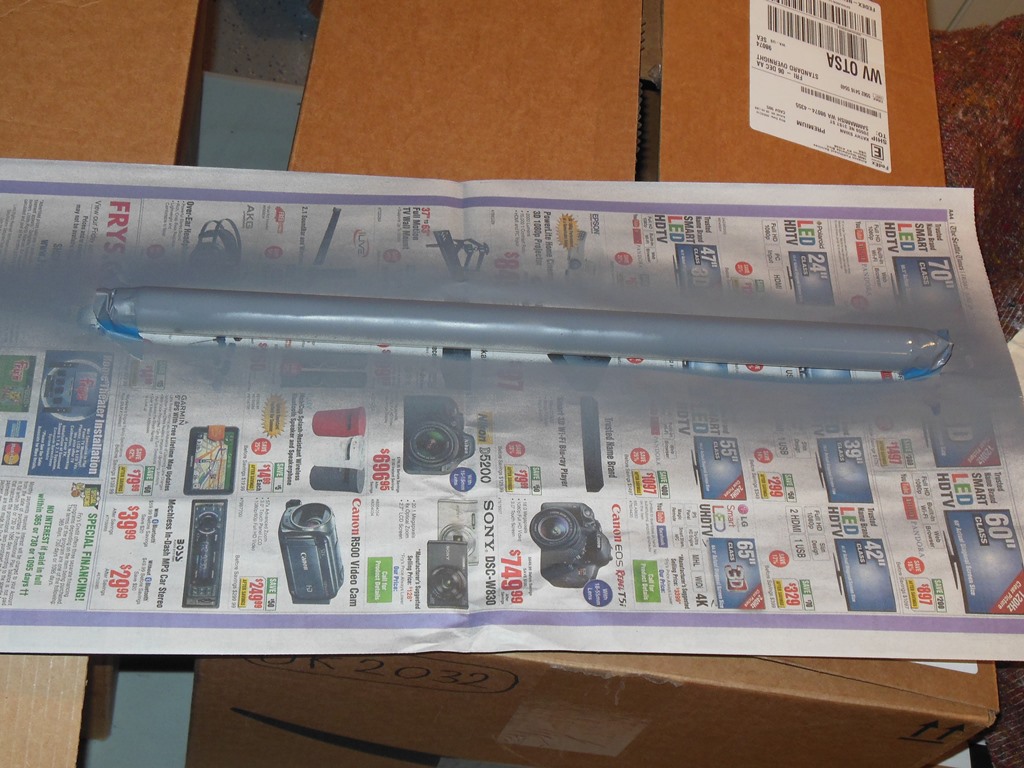
The seller did an excellent job of wrapping with a thick paper over a layer of cling film (that'd since disintegrated in storage).

|
|
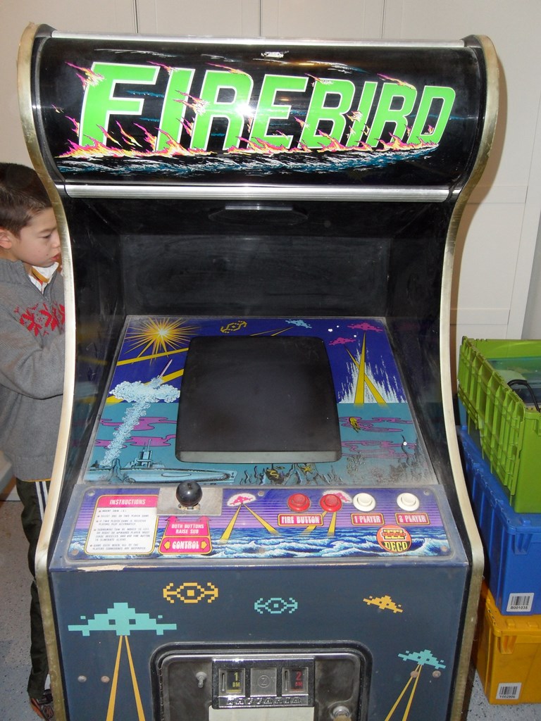
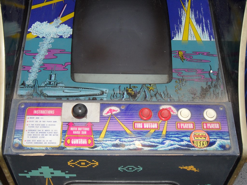
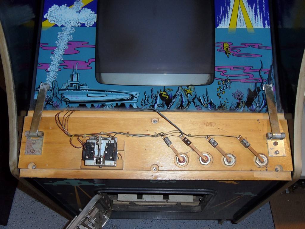
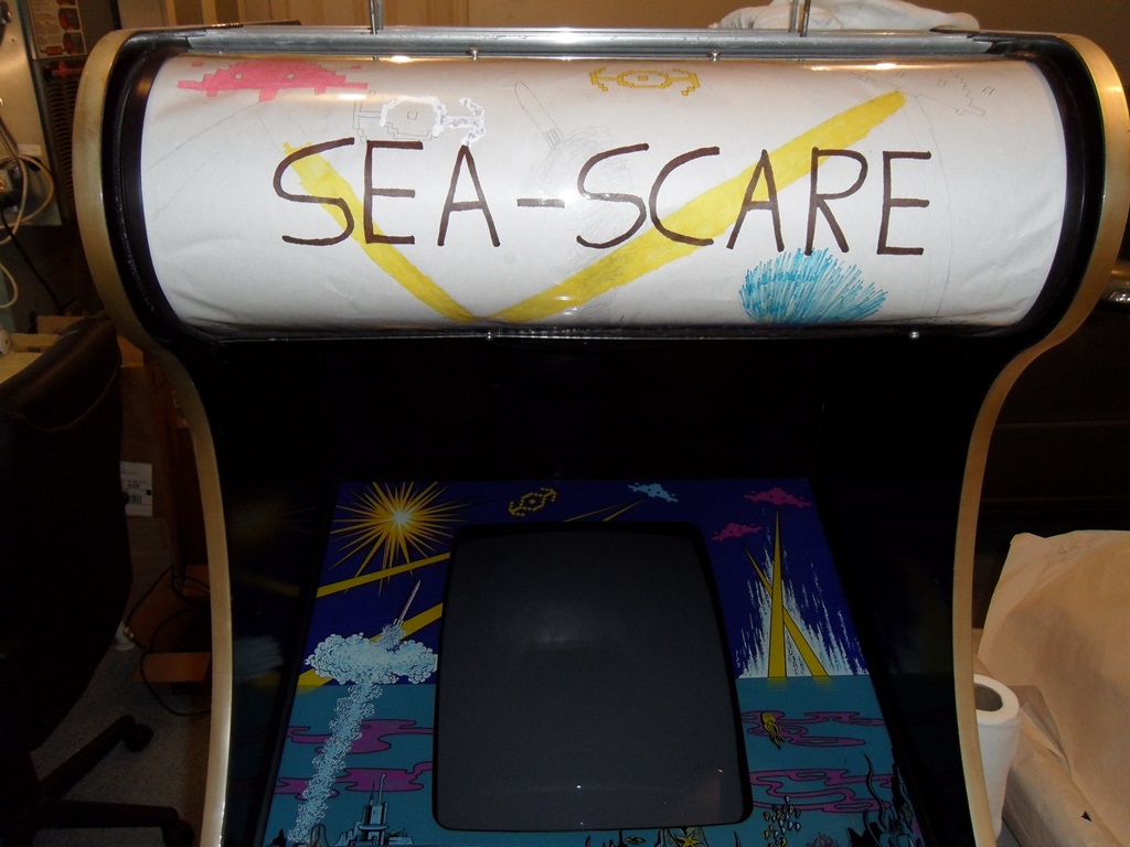
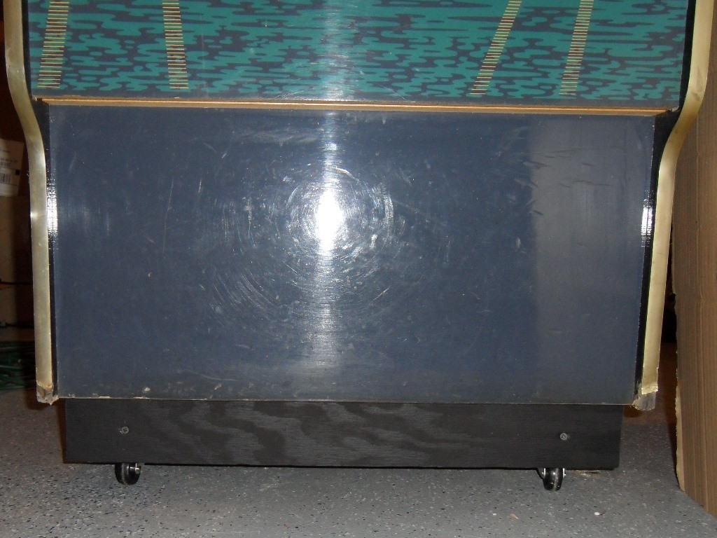
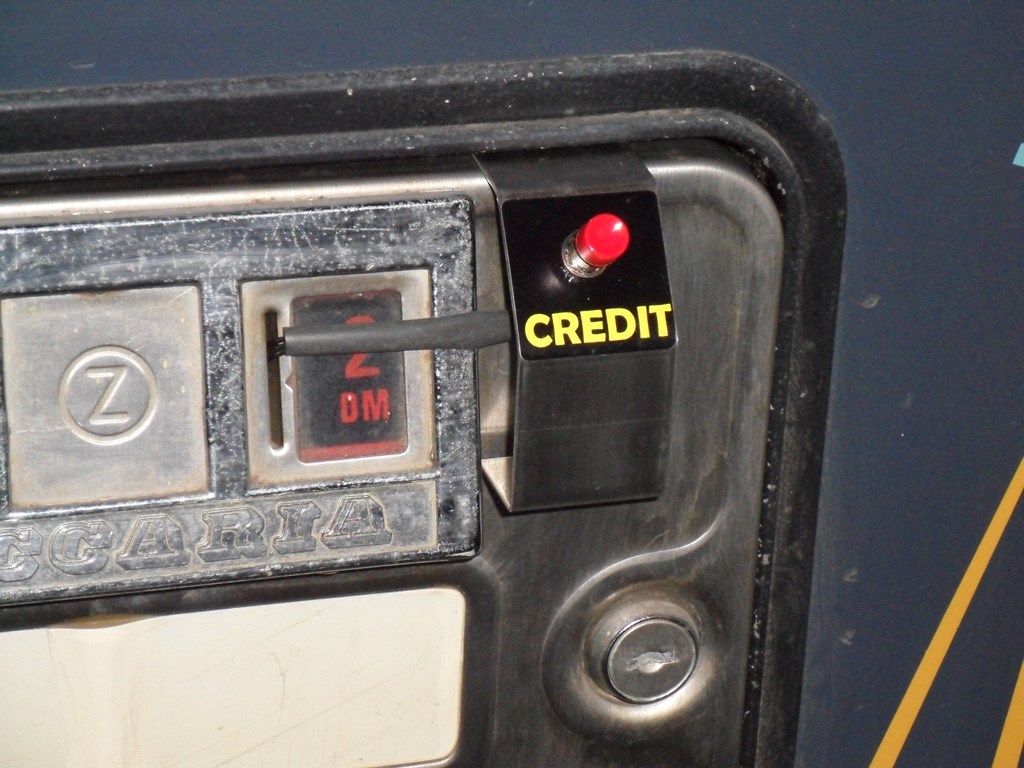
The artwork is in great shape. Missing the marque of course (and that's going to be a hard problem to solve). Control panel has been drilled for a joystick and an extra button that will need to be restored but there's enough of the art left to fill in the missing peices for a repro of that.

|
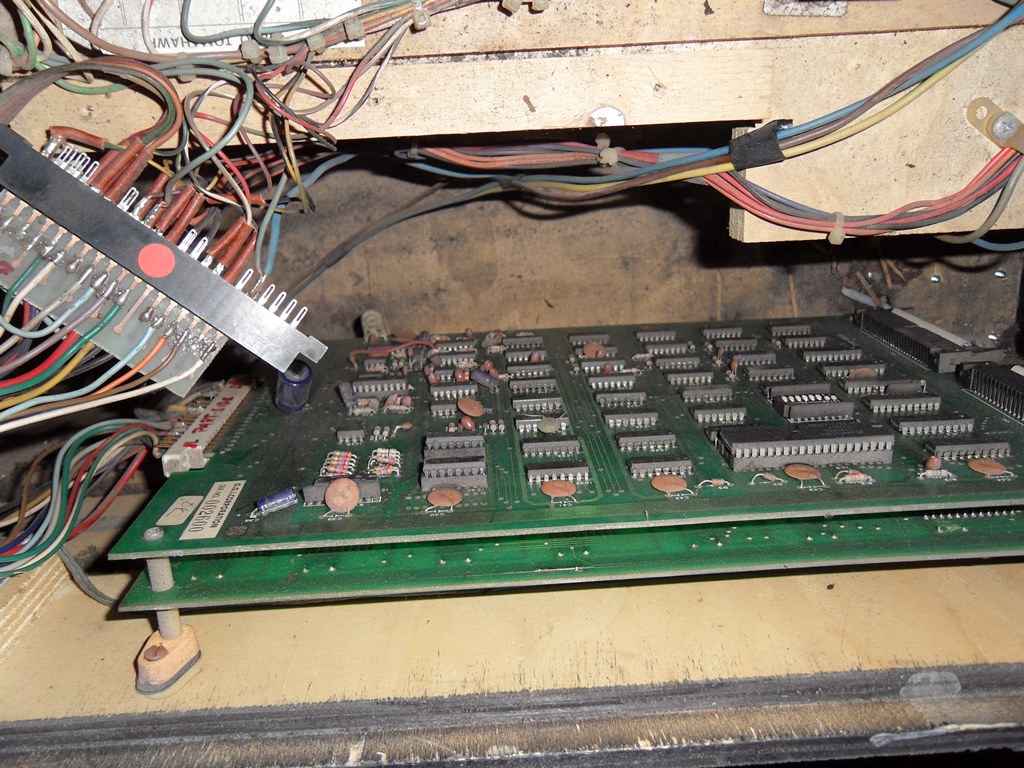
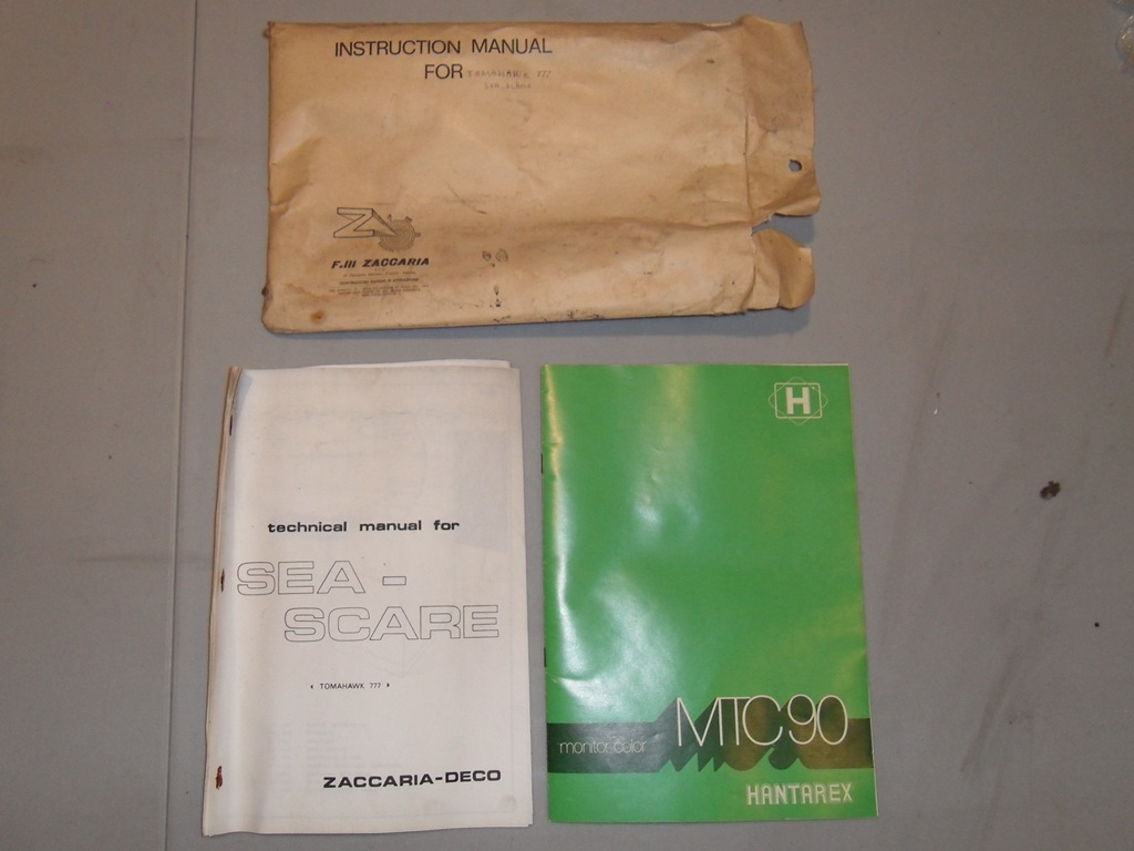
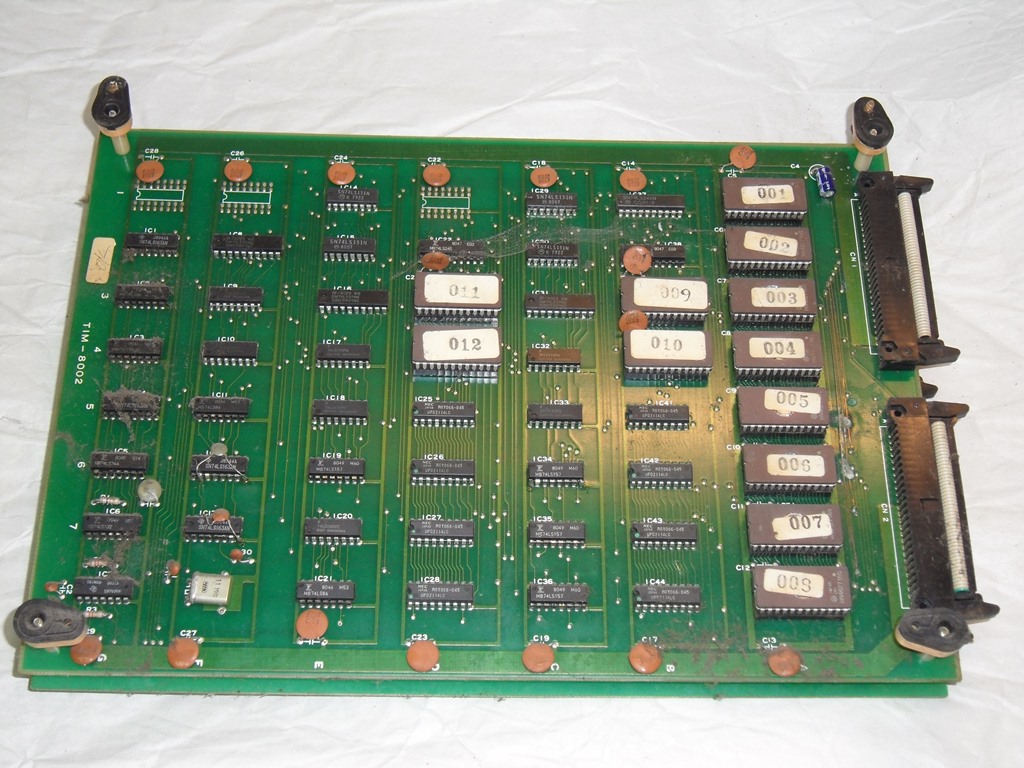
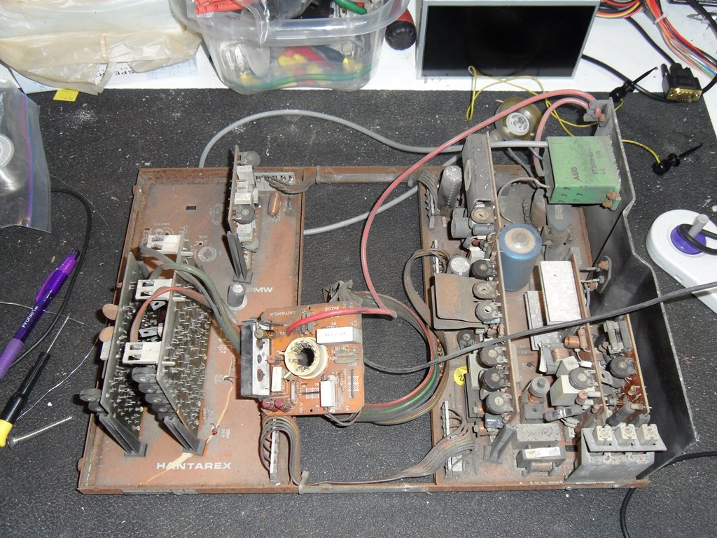
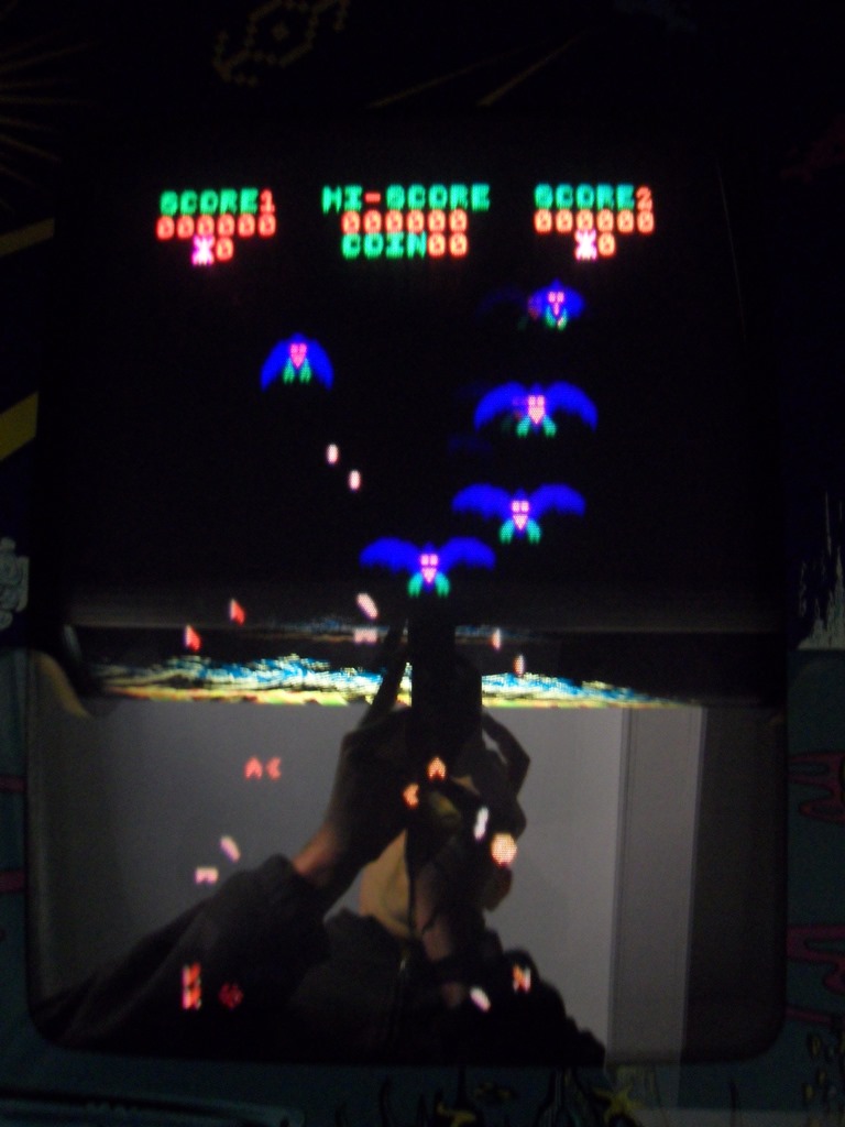
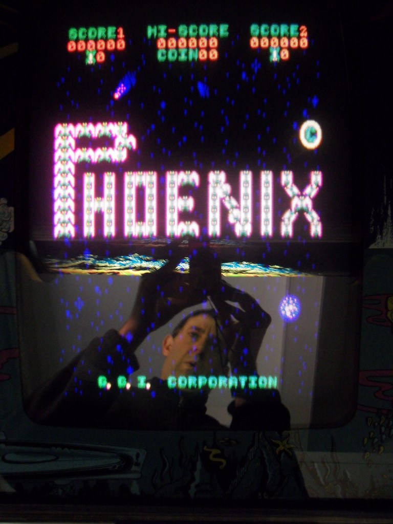
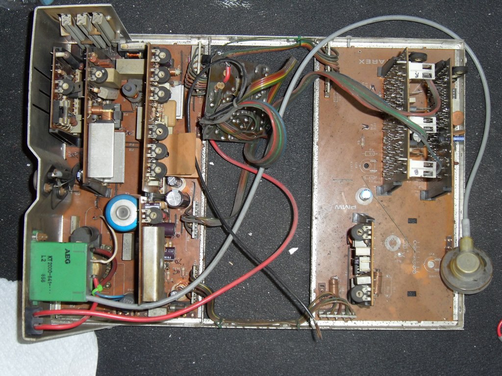
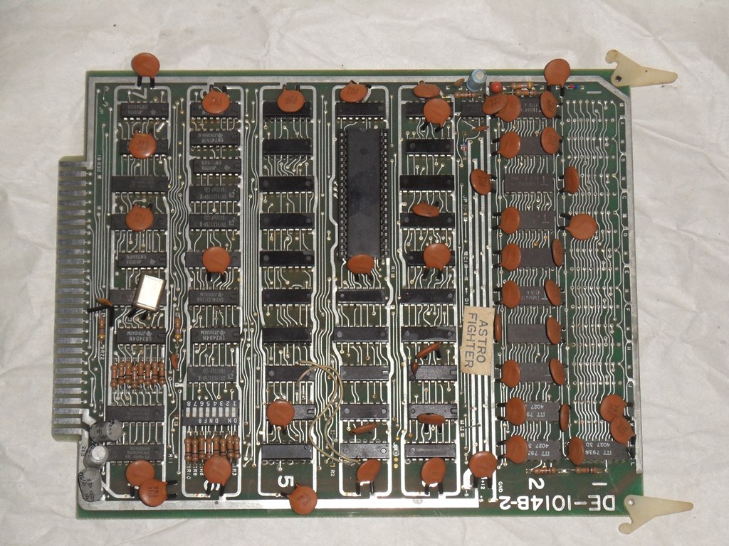
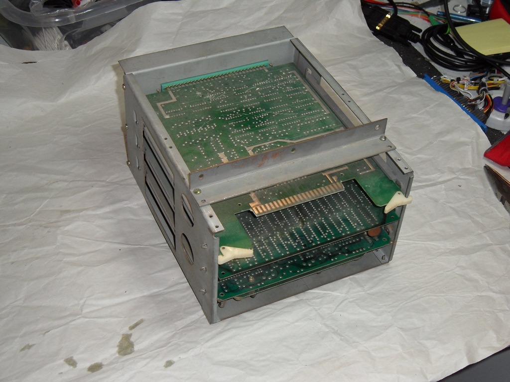
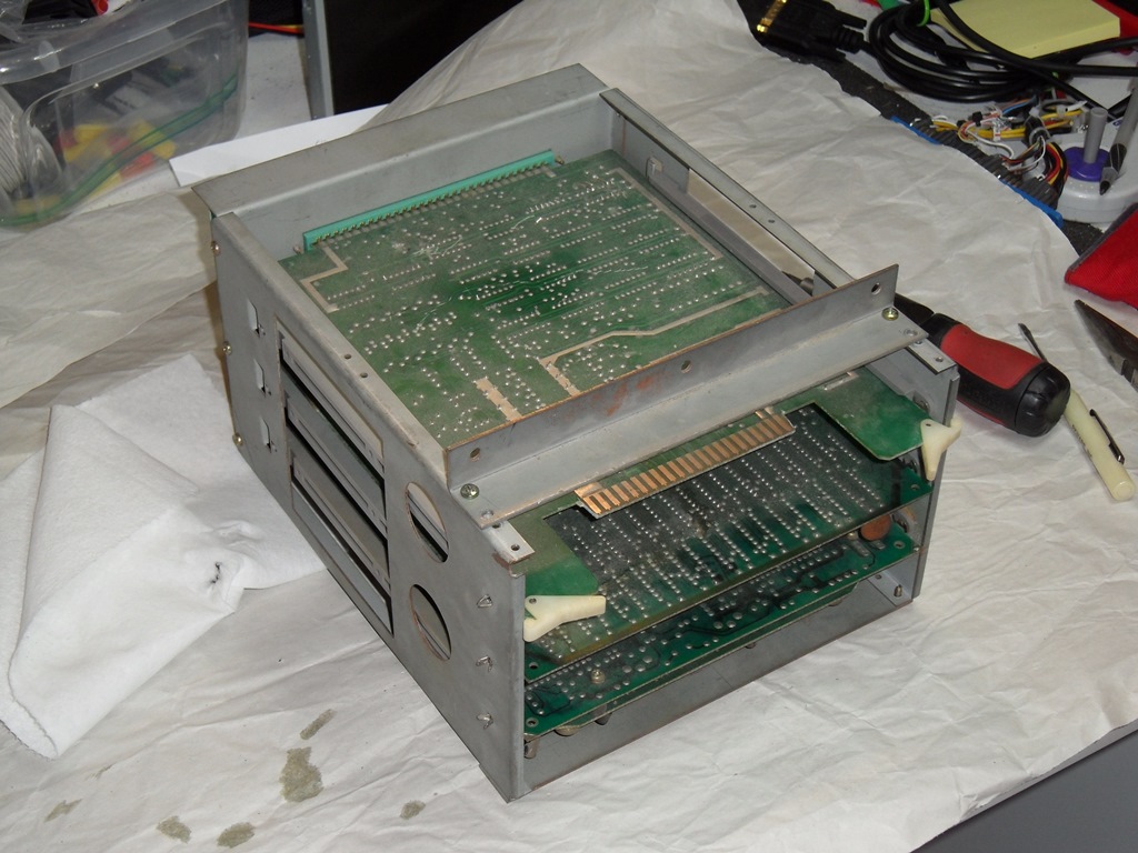
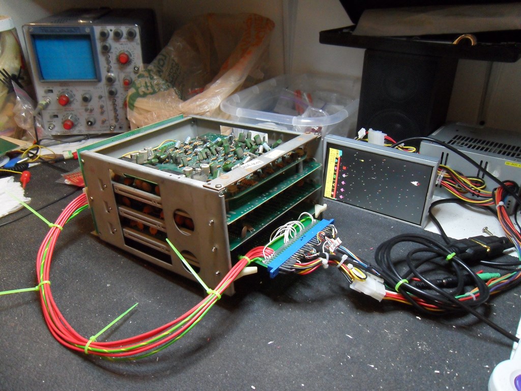
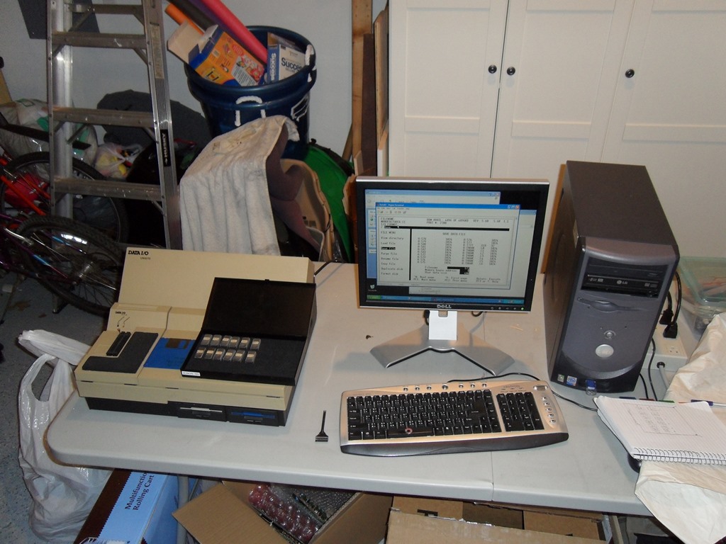
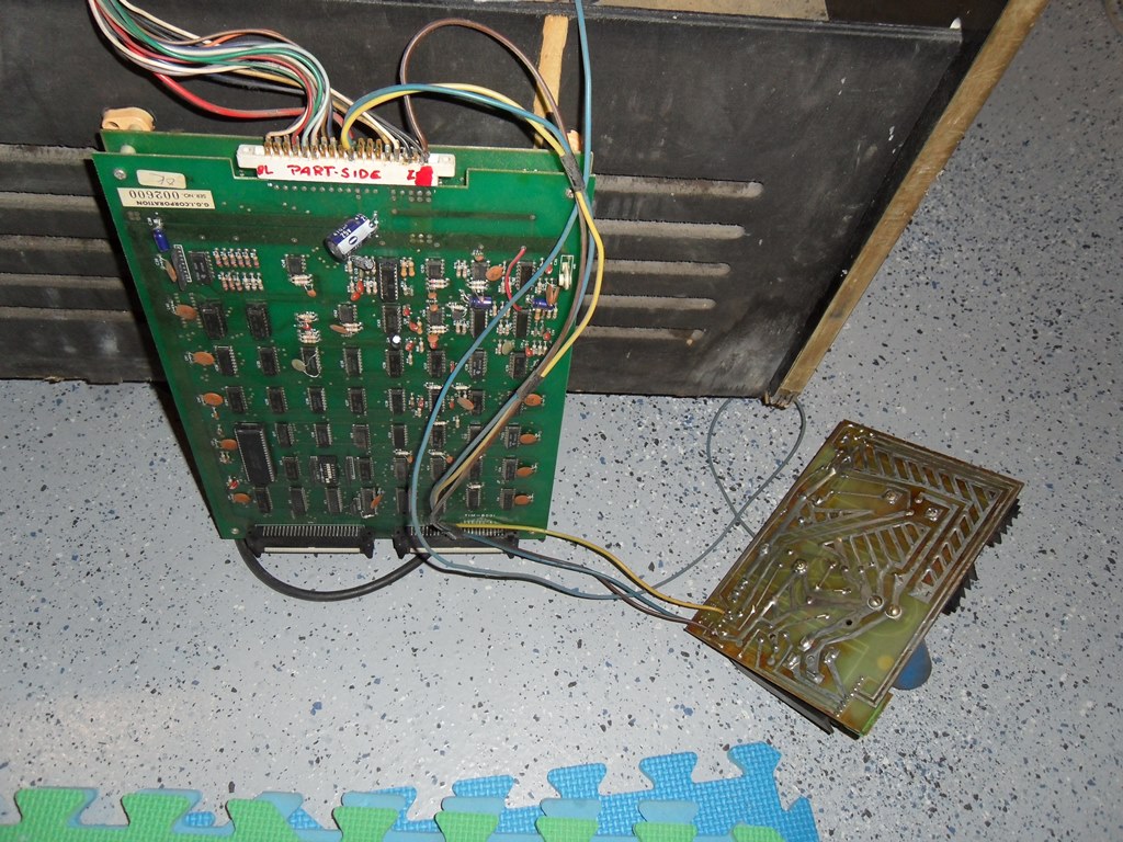
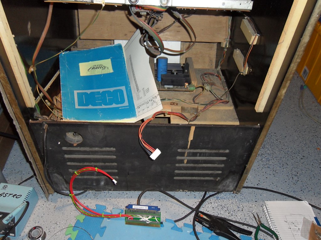
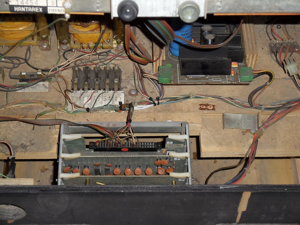
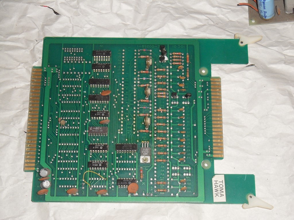
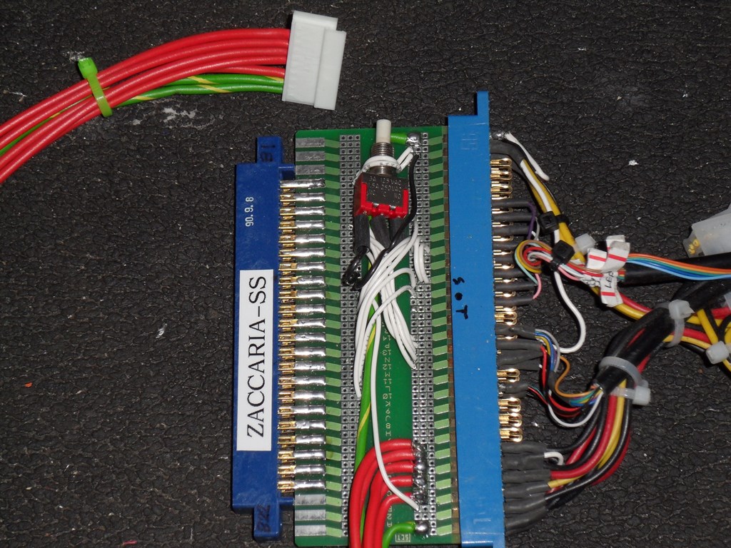
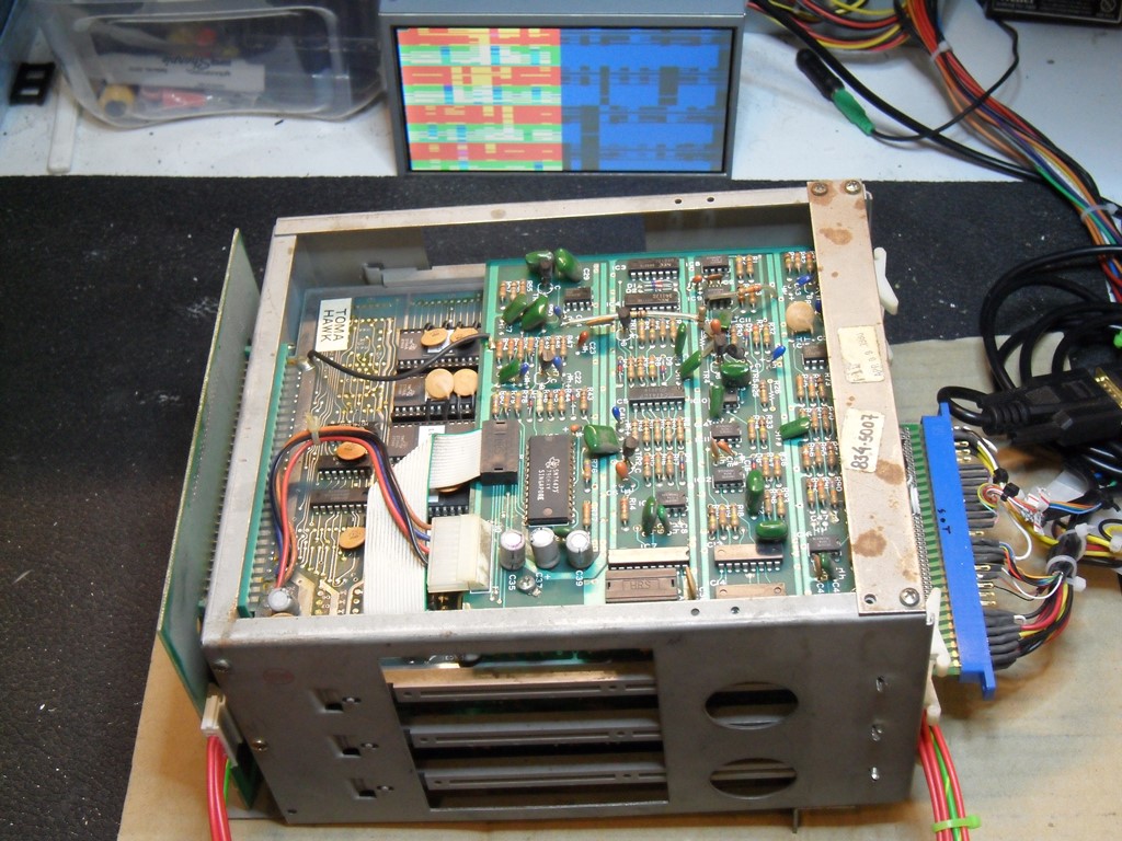
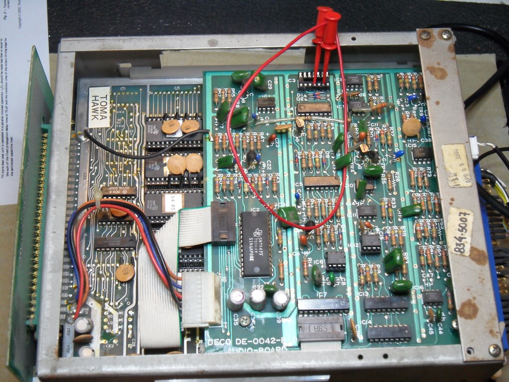
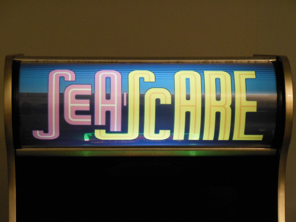
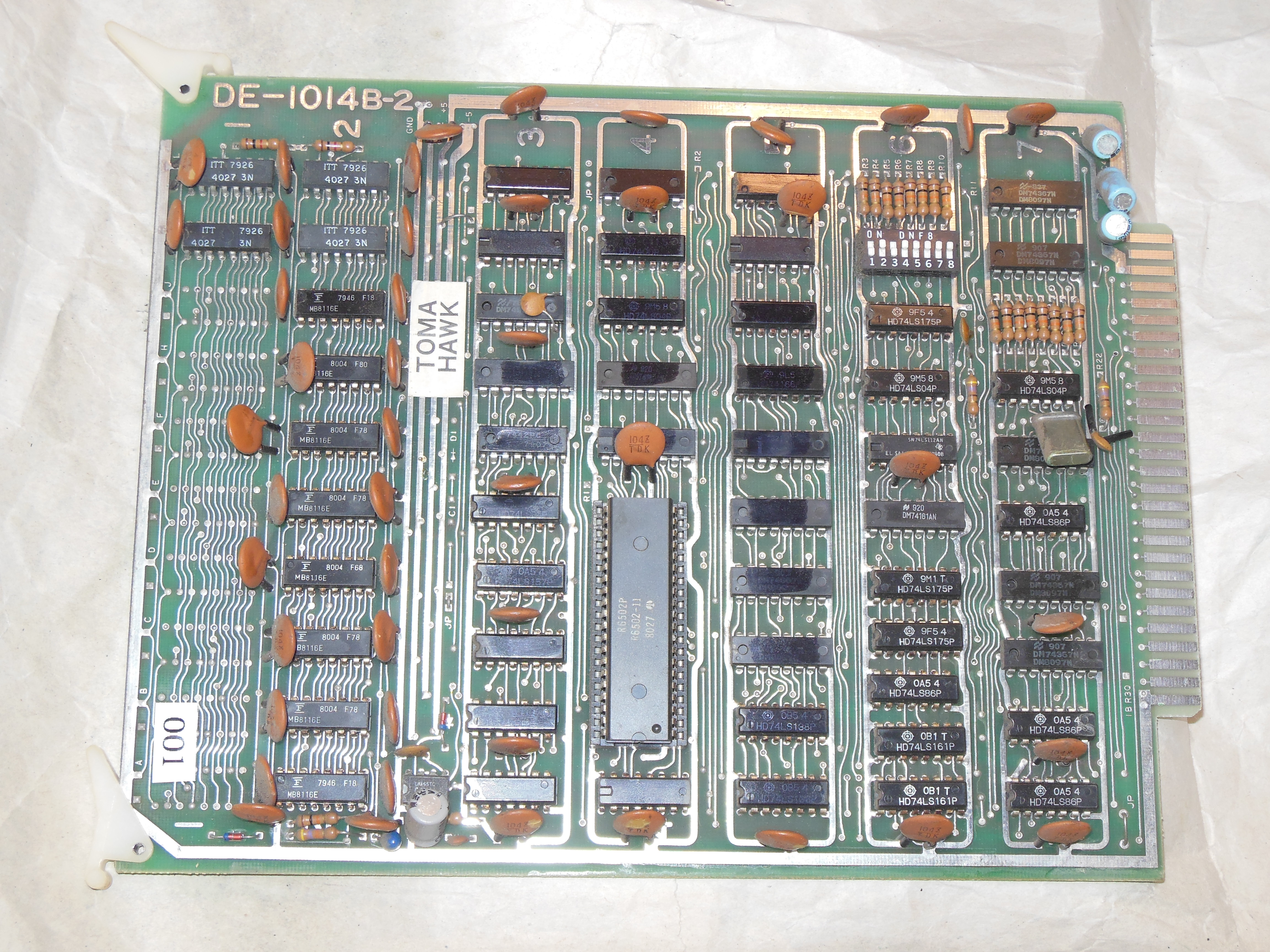
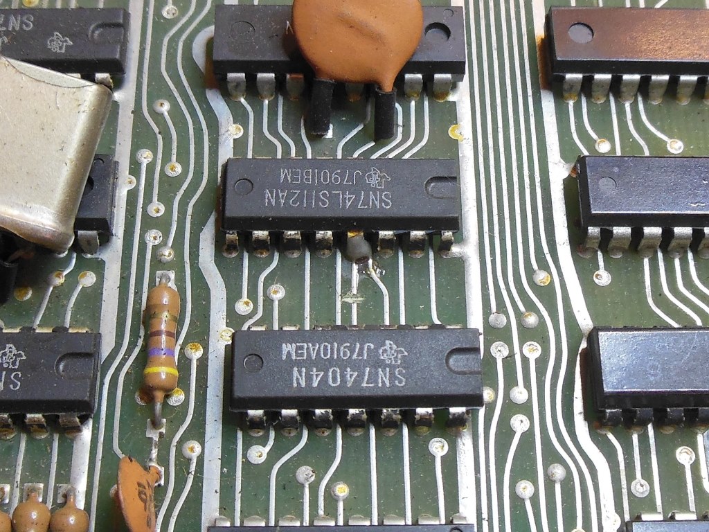
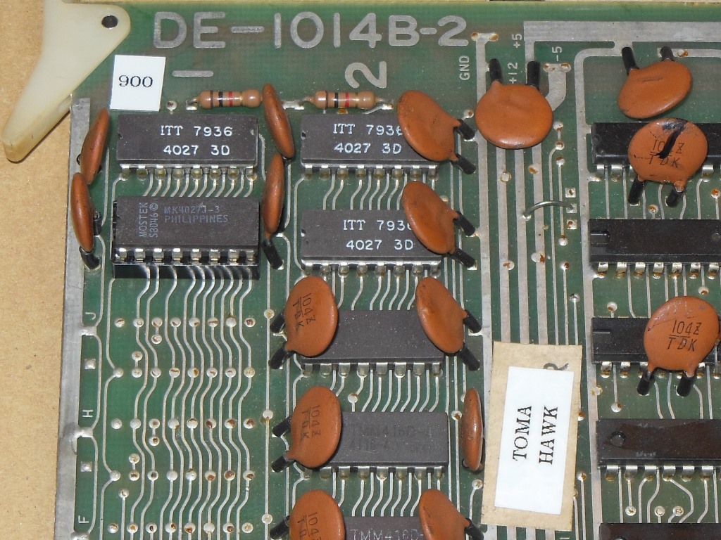
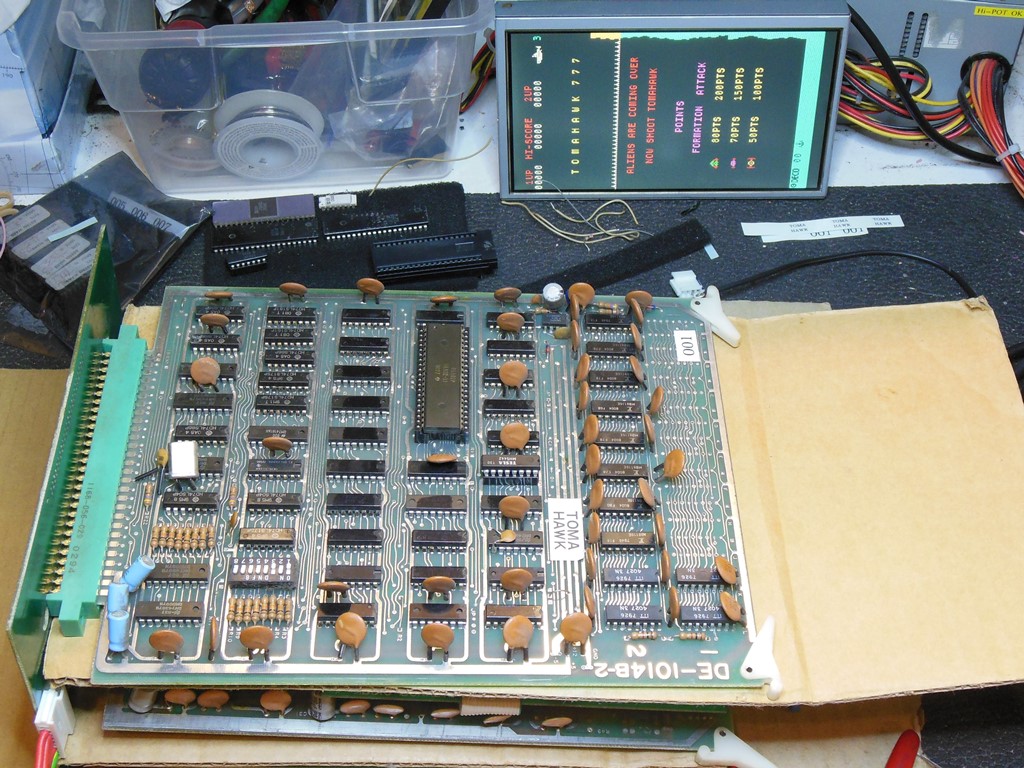
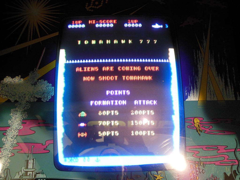
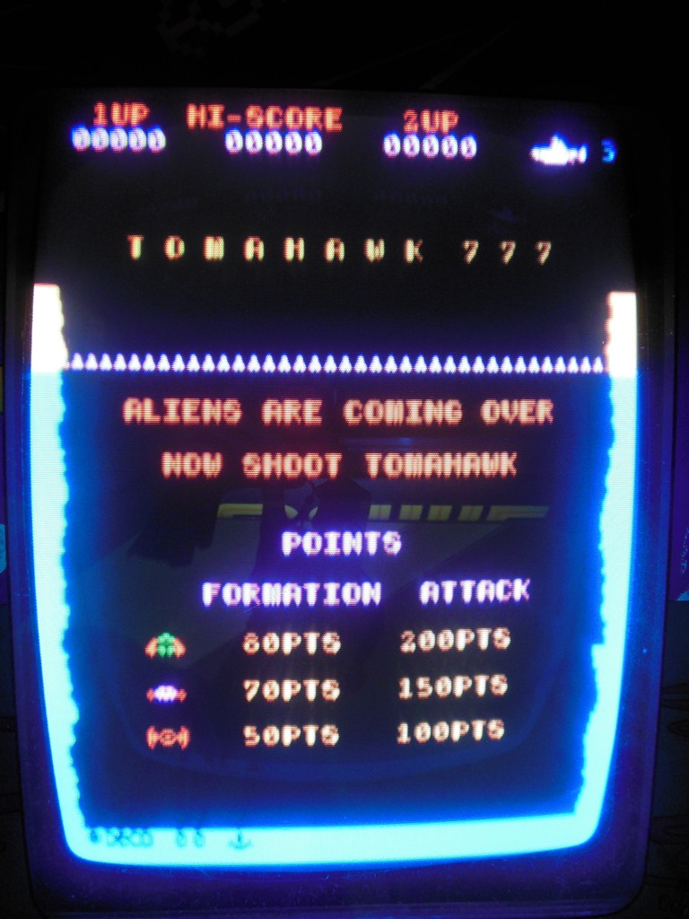
Finally some questions are answered :) The Zaccaria name for the game is Sea Scare and it's the same as Data East's Tomahawk 777. The game PCB is the dedicated Data East board set in a cage like Astro Fighter (not a Zac verison like Astro Wars). The conversion is not Space Firebird but an alternative name for Phoenix (it's a Phoenix game PCB that's in there). The wiring looks mostly complete with an adaptor used leaving the original wiring in tact.

|
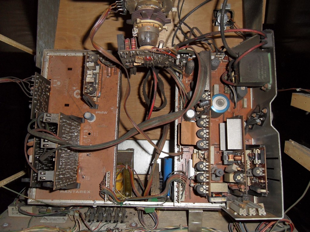
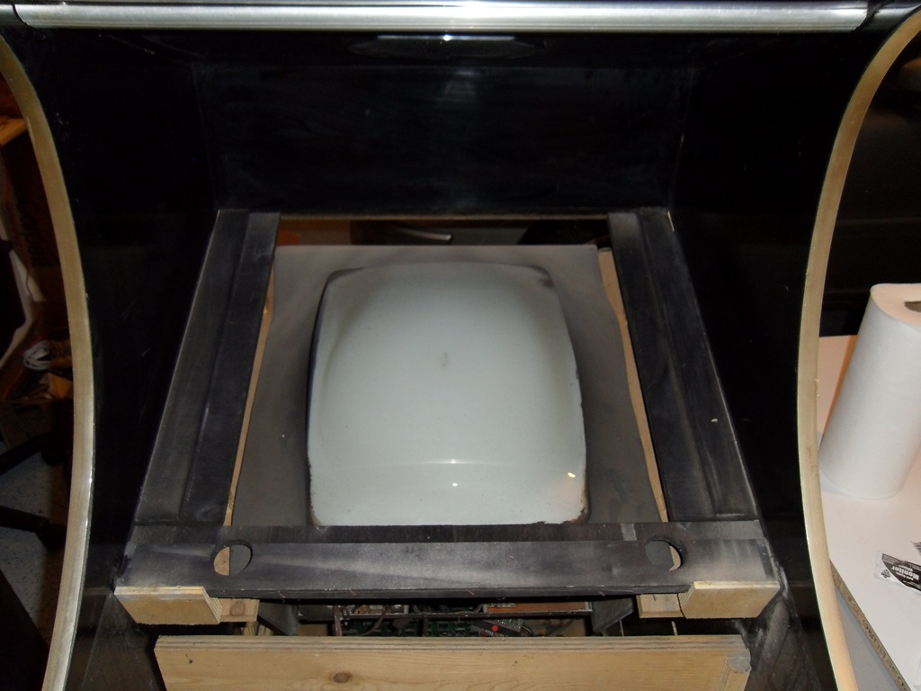
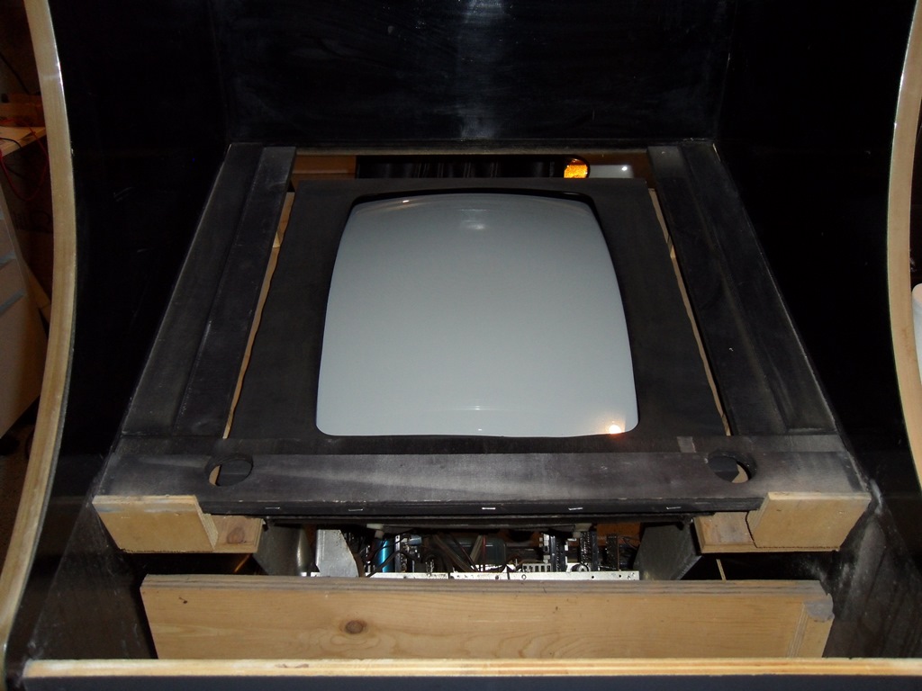
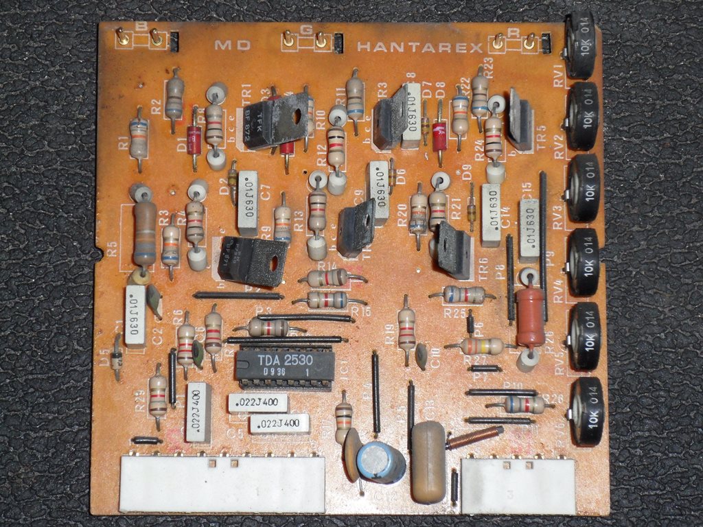
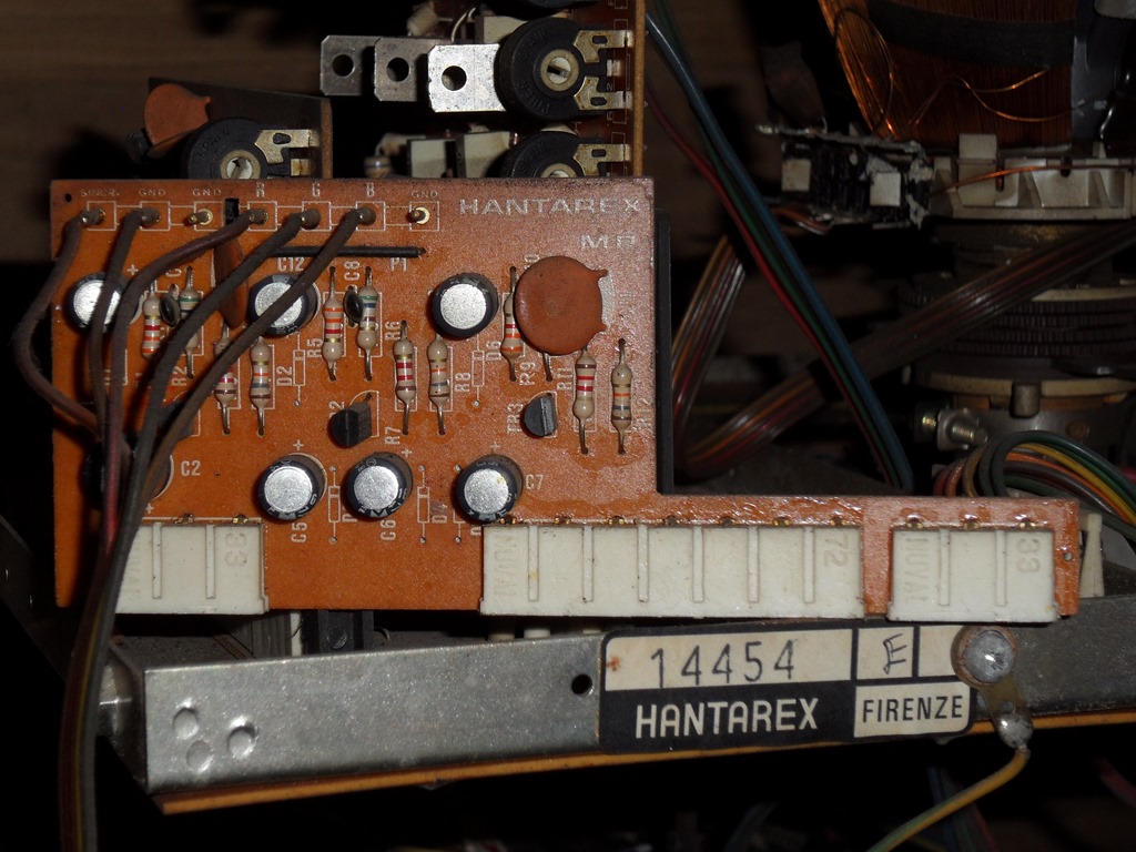
The monitor is the original Hantarex MTC-90 as used in the other cabinets of this style.
|
|
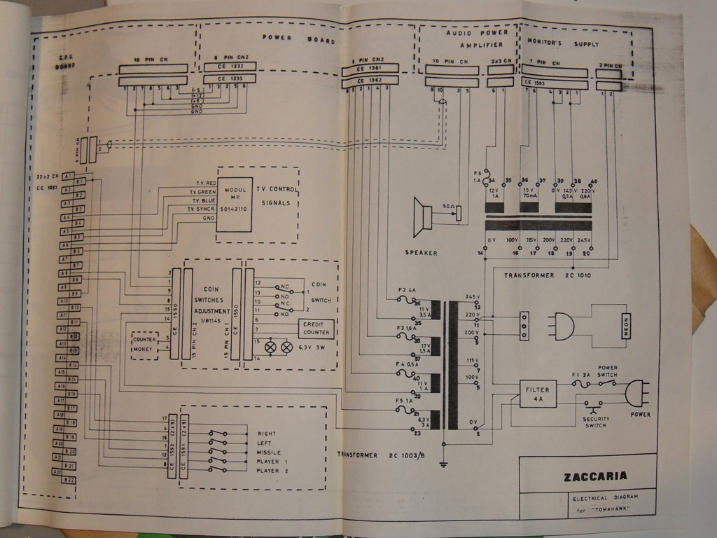
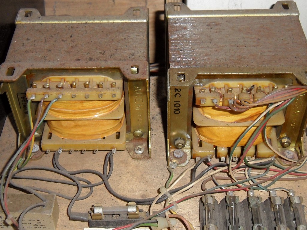
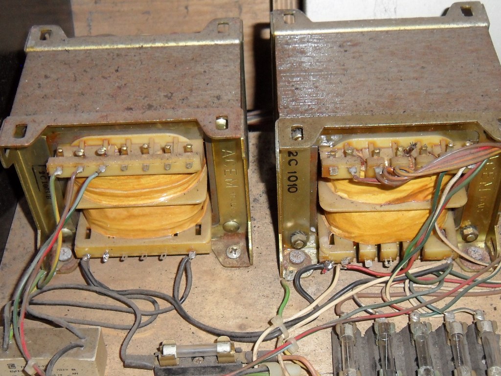
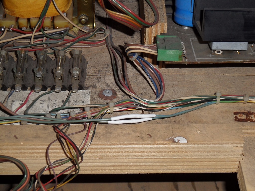
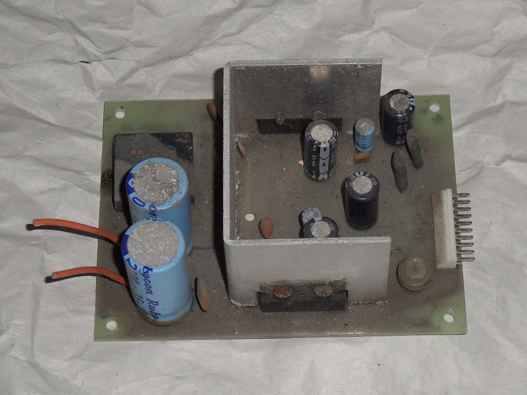
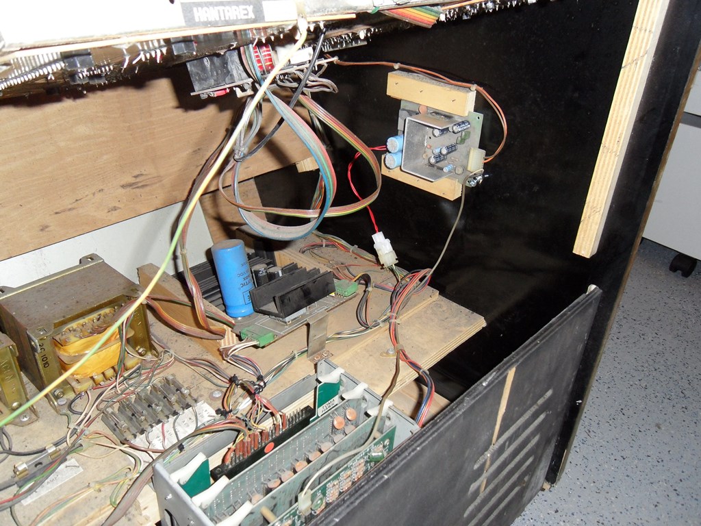
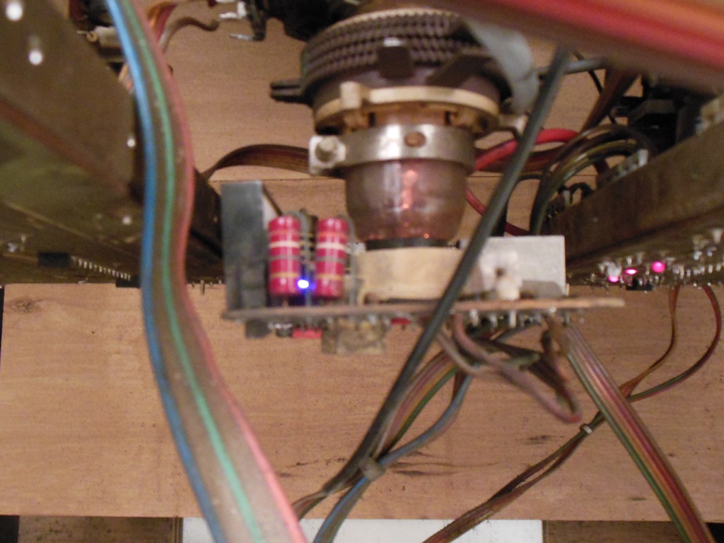
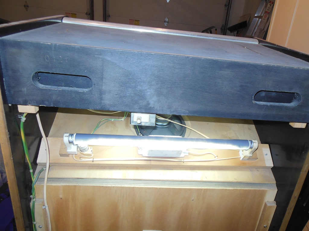
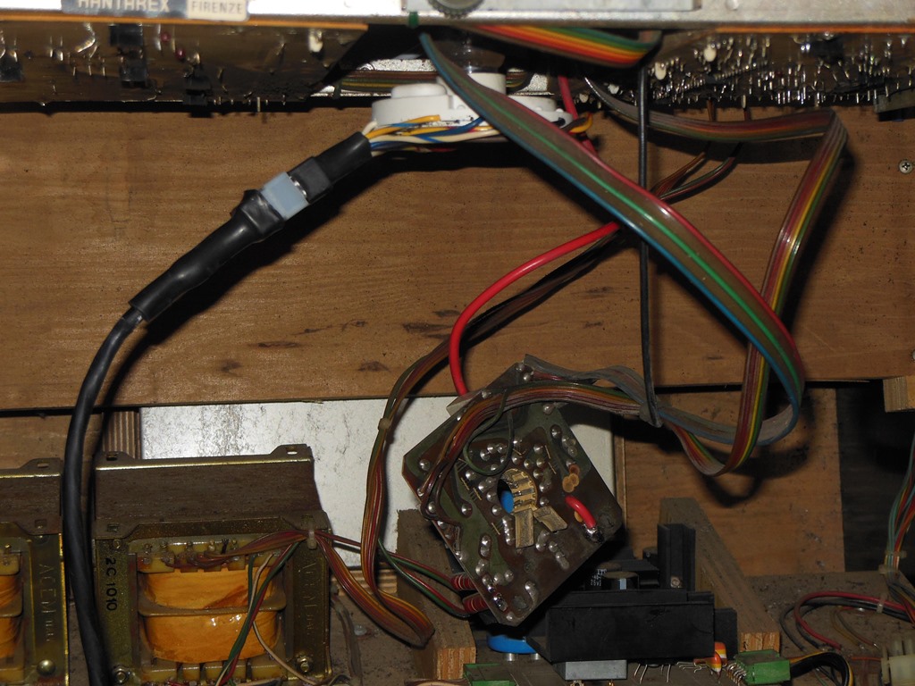
Unlike the later Zaccaria cabinets with a simple voltage selector plug this early cabinet has twin transformers that both need the taps resoldered to select the 245V input tap. On later cabs, the marque light is 220v-240v and tapped off the line side but this one is rated 220V so I decided to keep it off the 220V tap along with the monitor degauss 220V. Thus, two wires stay on the 220V tap and the line input moves left one tap to the 245V input. Since I'm making some educated guesses on this one (having never done this conversion before) I'll be doing first power on with transformer outputs all disconnected to measure the voltages first.
|
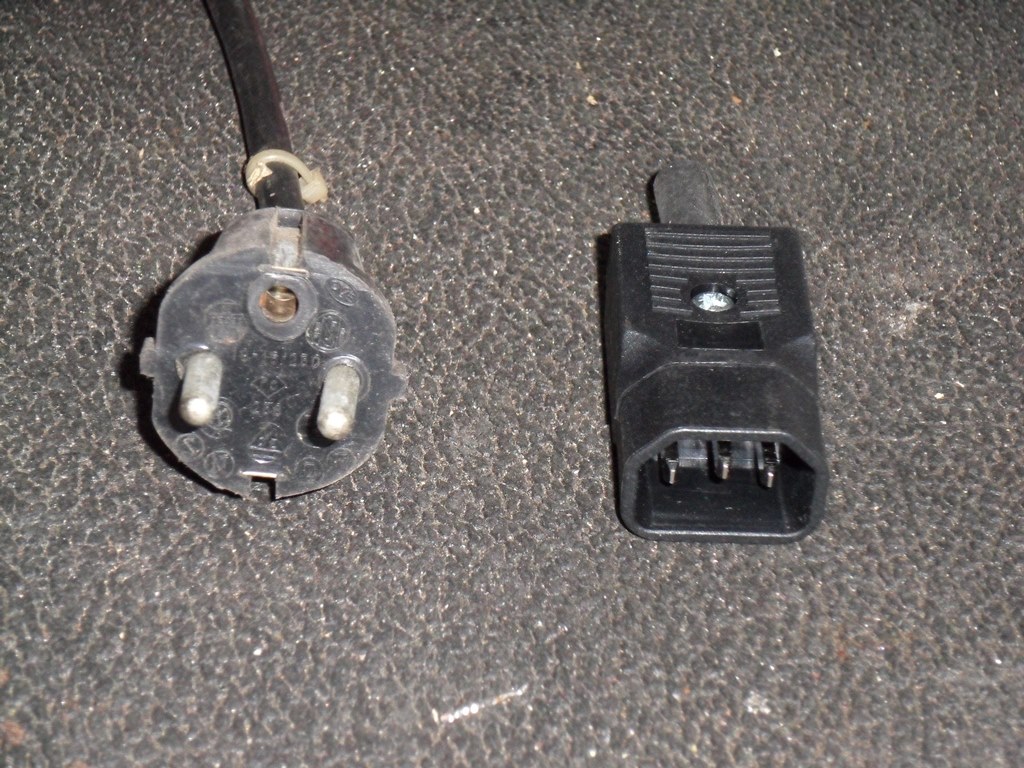
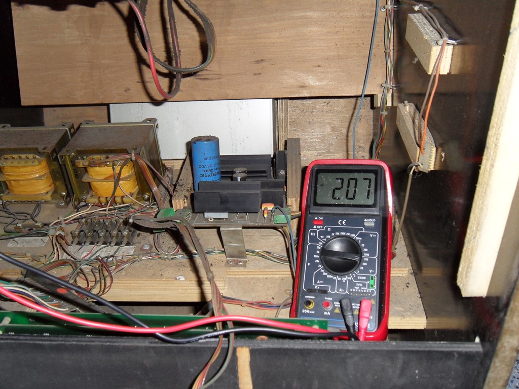
After converting the line cord from German to IEC14 and disconnecting the iso-side (including the awkward monitor power connector located at the back of the chassis) initial power on yielded line-in at 230V, marque light 220V @ 207V, 17V @ 17.2V, 11V @ 11.2V, 143V @ 138V. Not too bad. The marque light flickers on periodically so I did try the 240V line in directly on the light but it still didn't stay on so it needed to be fixed.
|
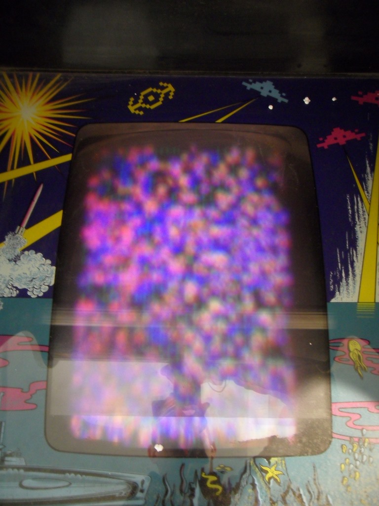
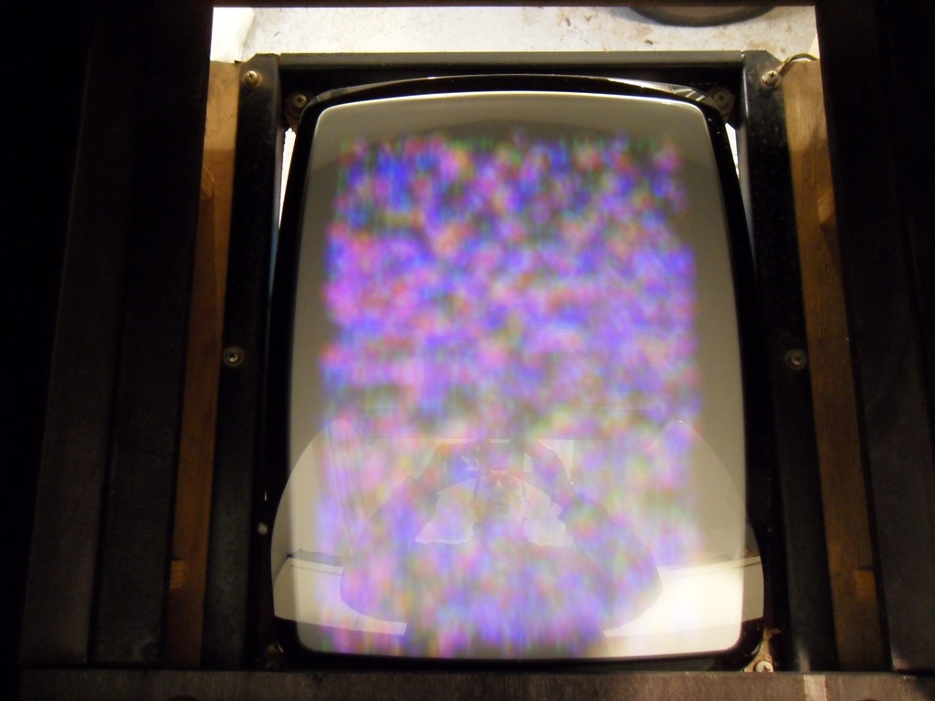
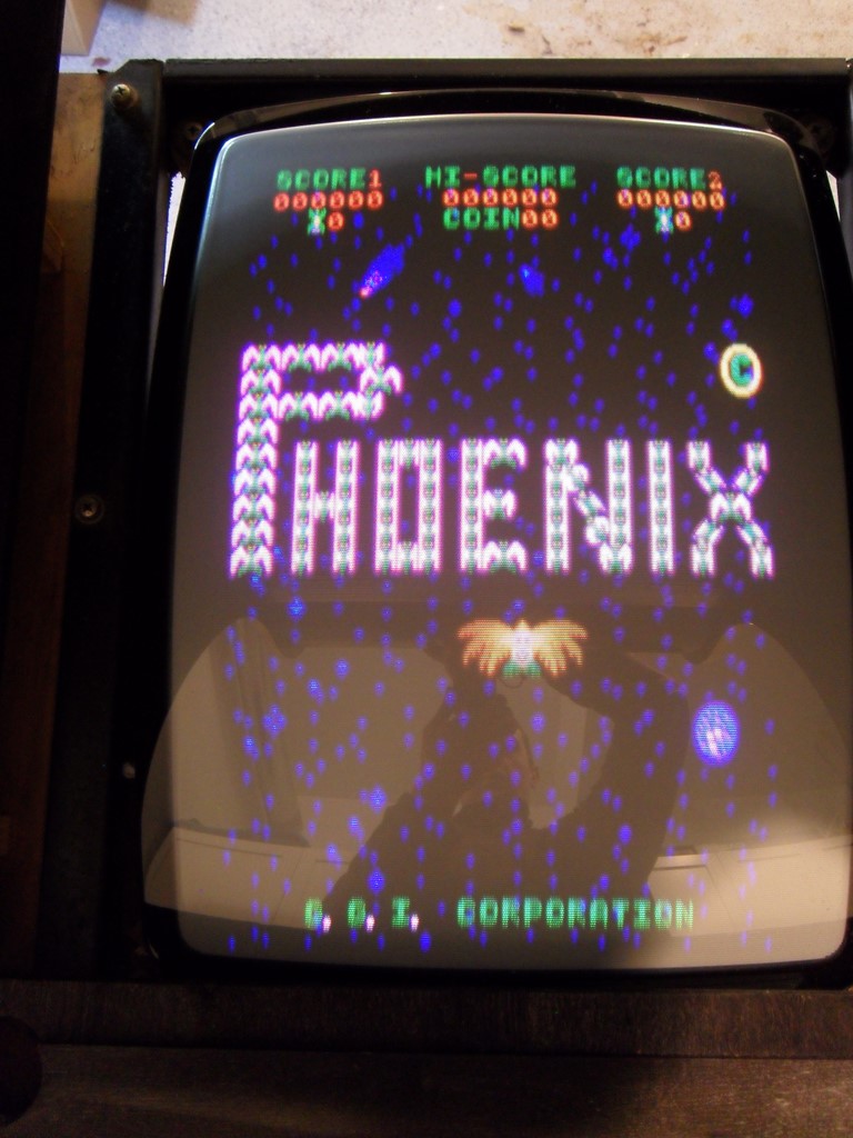
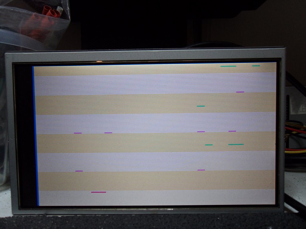
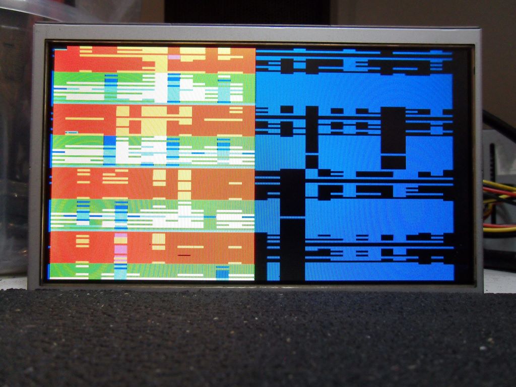
Reconnecting everything and going for a full power on yielded a dim out of focus picture and the Phoenix game PCB not booting. Periodically there was some arcing around the focus pot on the neck board :(
|
The extra button appears added to the existing spare/unused button position in the panel wood and a long single lead from it runs all the way to the edge connector. The joystick conversion is very neat and tidy and looks have minimally cut through the wood and overlay.
|

|
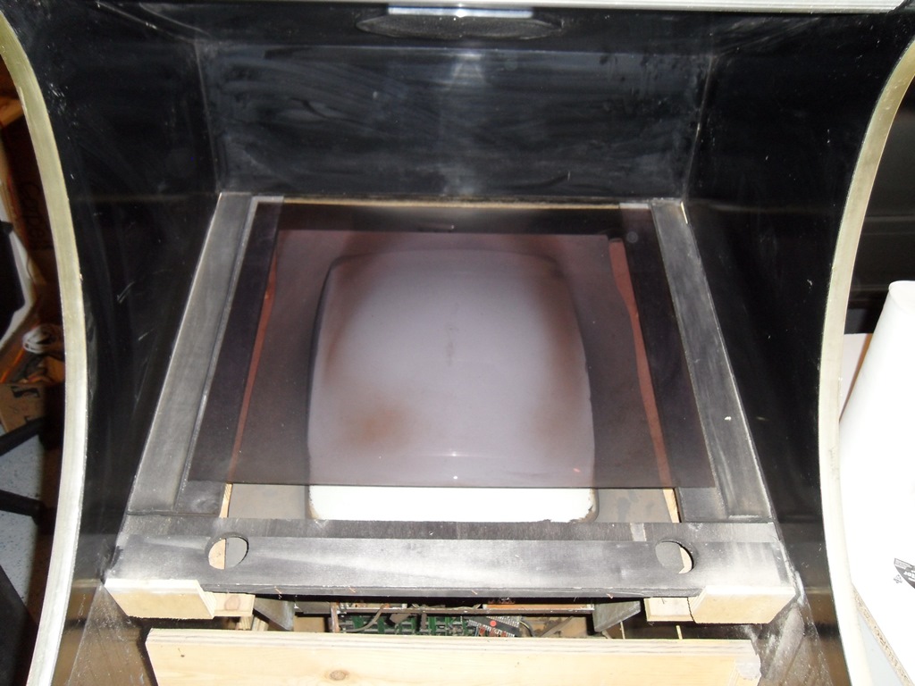
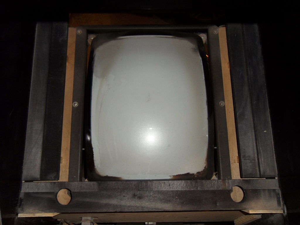
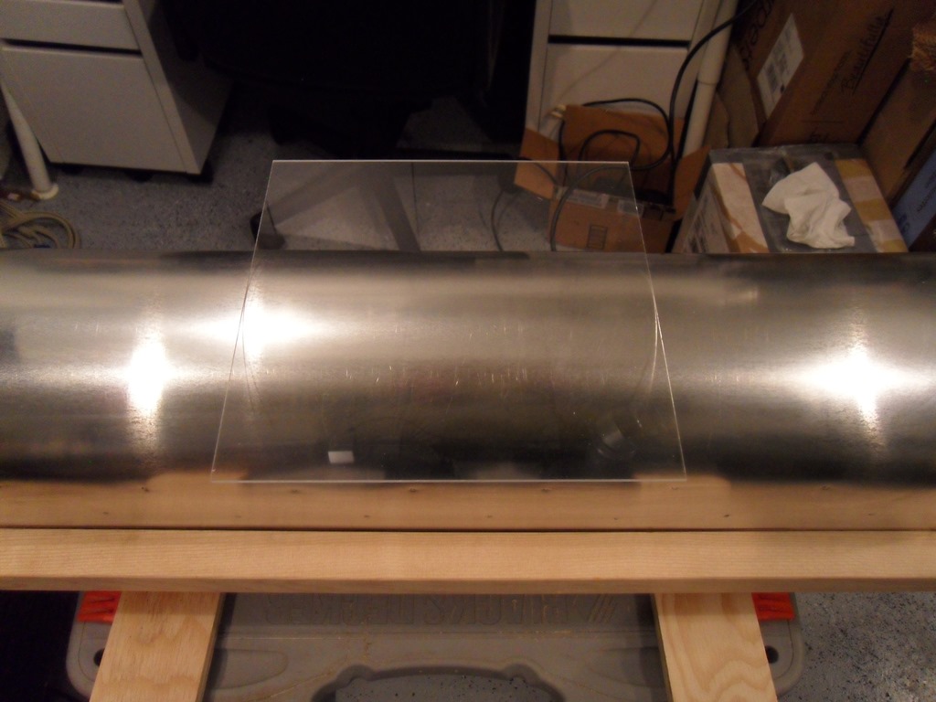
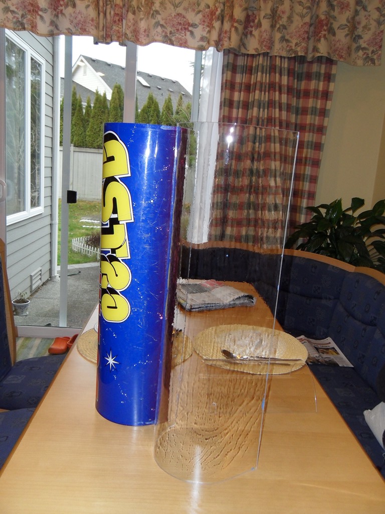
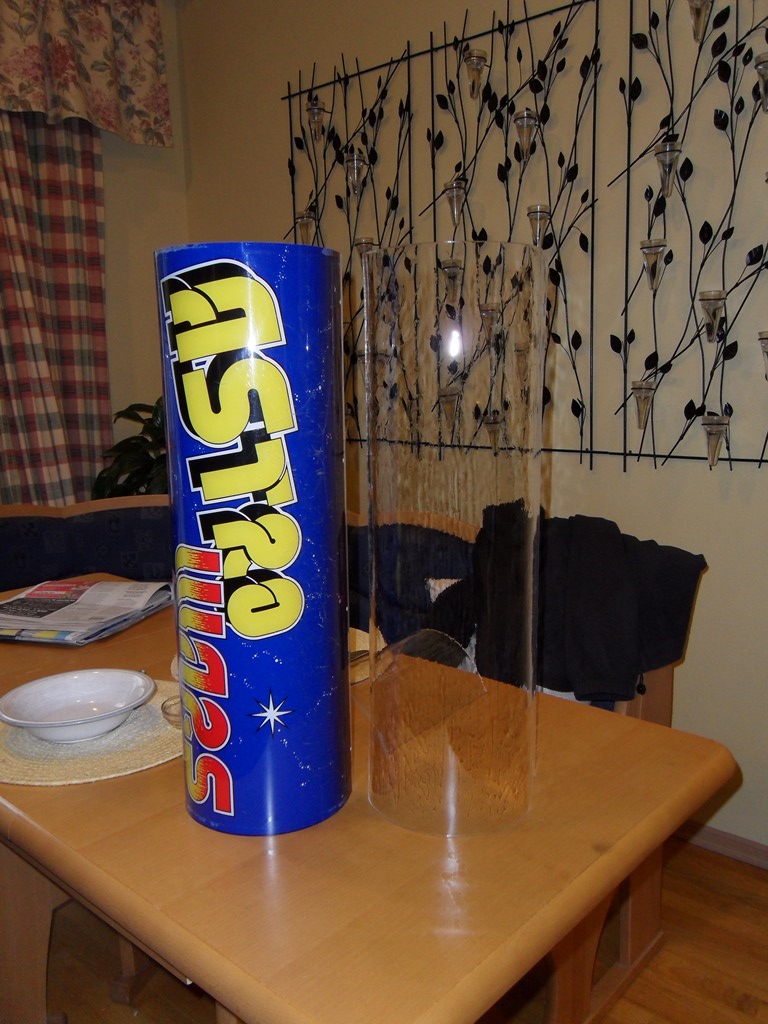
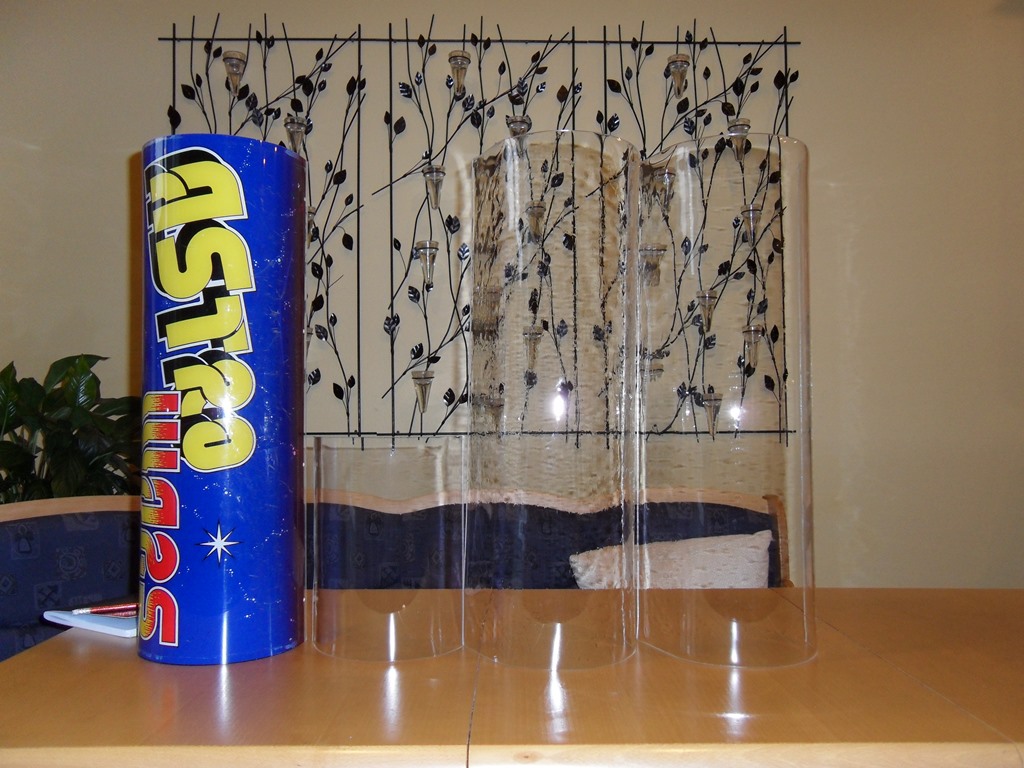
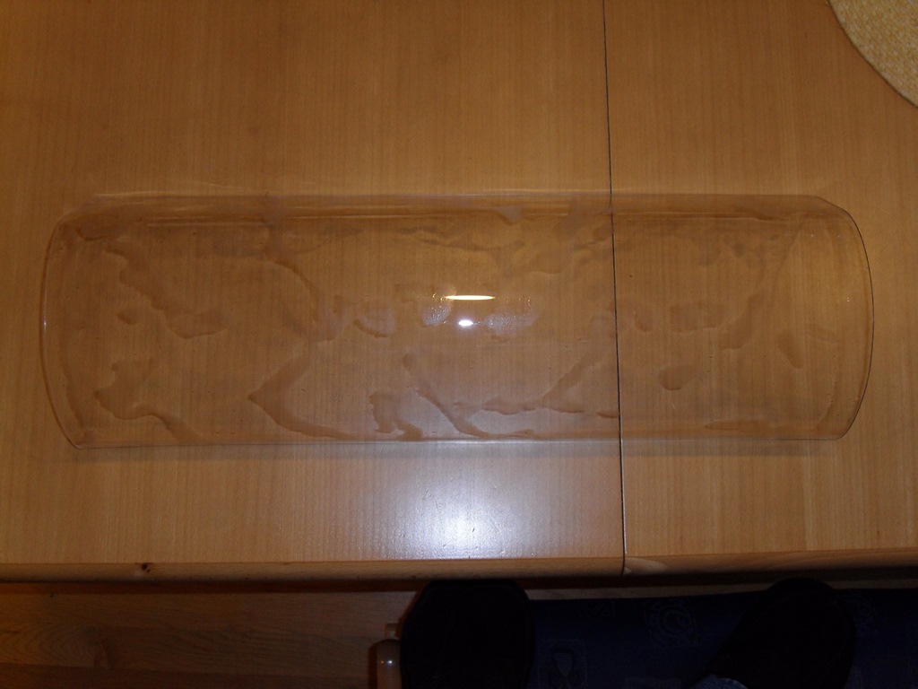
The smoked perspex doesn't look like it fits the cab so I'll see how it compares to the one in Astro Wars. There's a small cardboard surround that's complete but needs some cleaning, flattening & restoration. Everything has thick nicotine staining. Baking soda was the best for cleaning the monitor tube but still needed alot of elbow grease :|

|
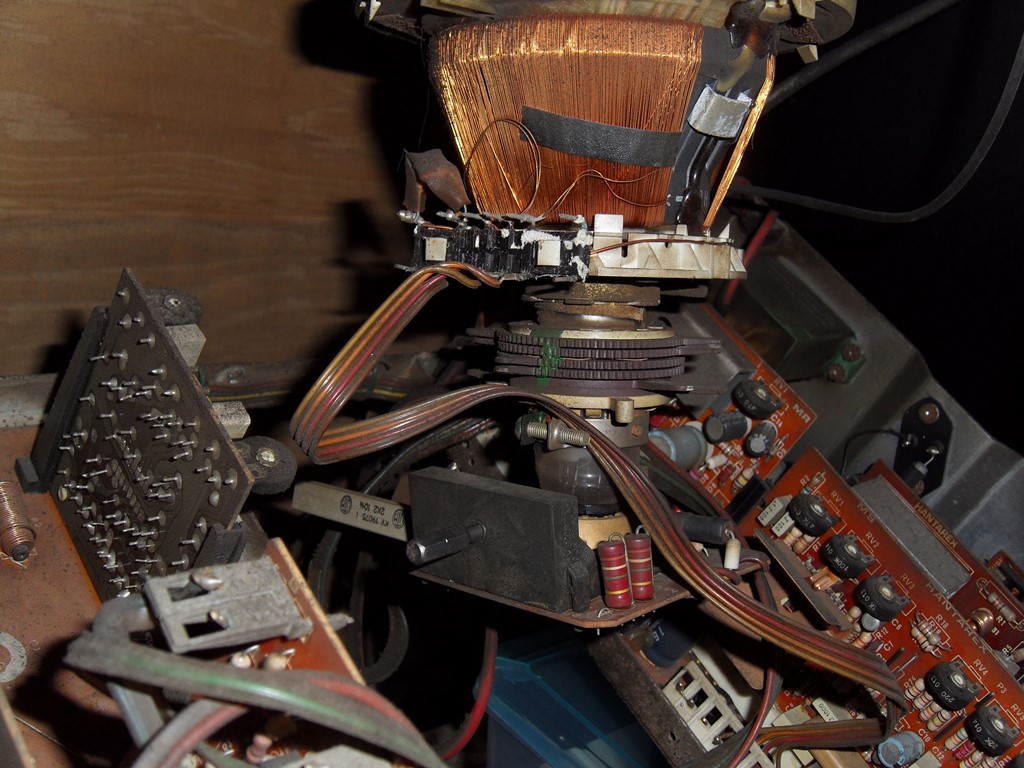
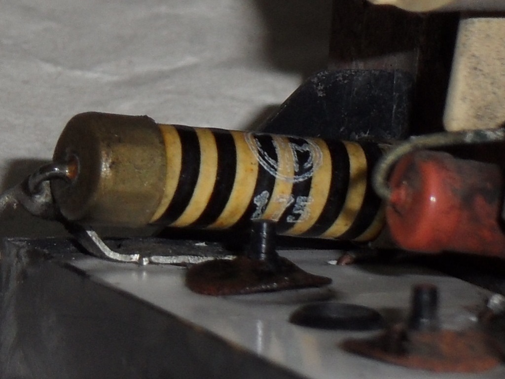
After cleaning it was still dim and out of focus with periodic sparks on the neck PCB. A little bit of inspection found a small metal strip shorting out the focus pot that may have fallen off the yoke. That giant resistor on the neck PCB doesn't look like it's supposed to be there.
|
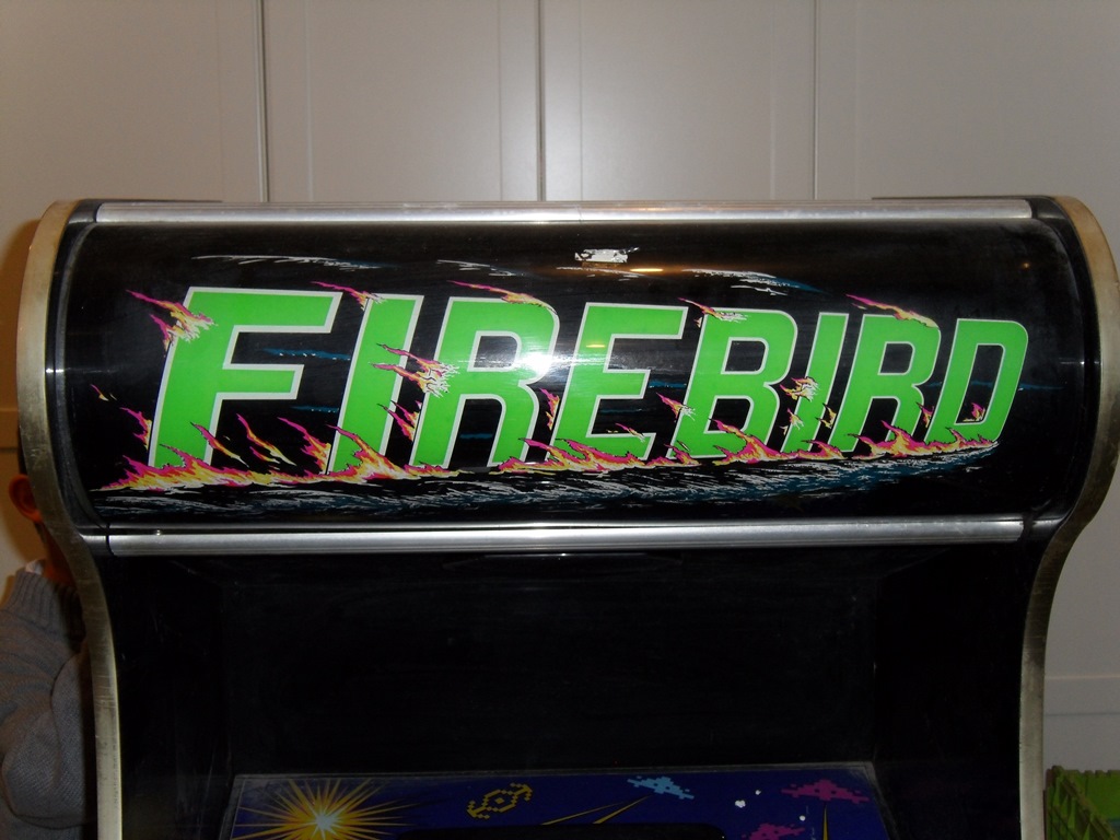
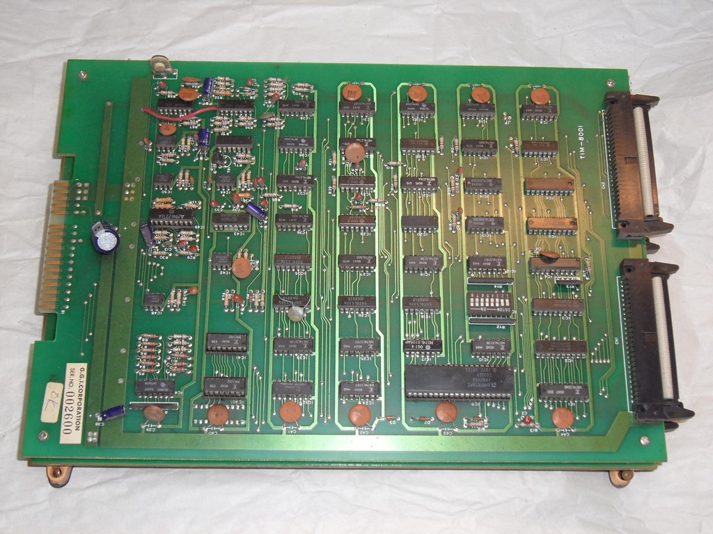
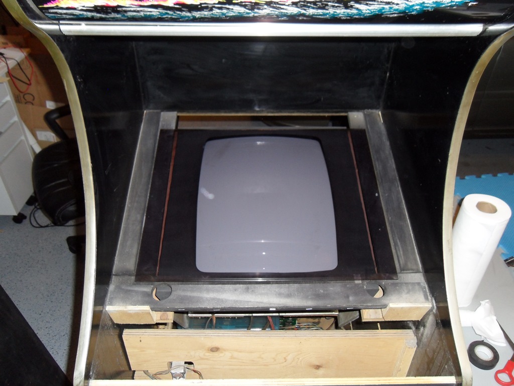
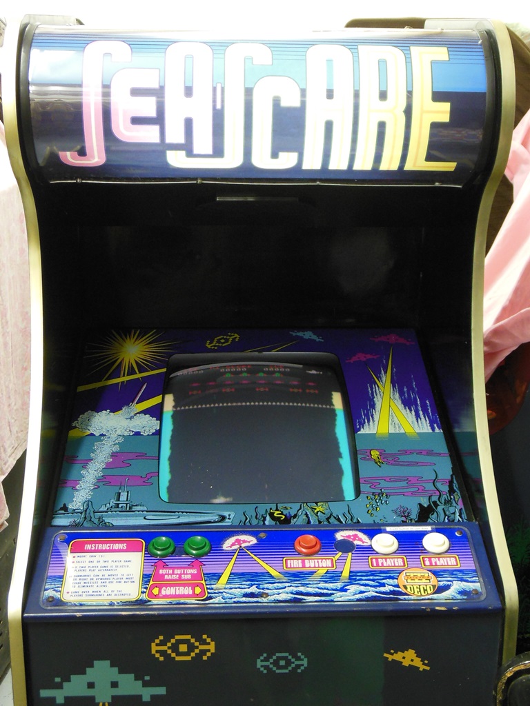
With the metal fragment removed the focus pot worked and it pulls in to almost focussed (just a little off). Turning up the brightness bled the picture at high brightness but went up enough to give something useable. Popped out the none-booting Phoenix PCB that looks like a stock GGI version. It'll be interesting to see if it's running with the Firebird game name. MAME does not list a version of Phoenix with a Firebird title.

|
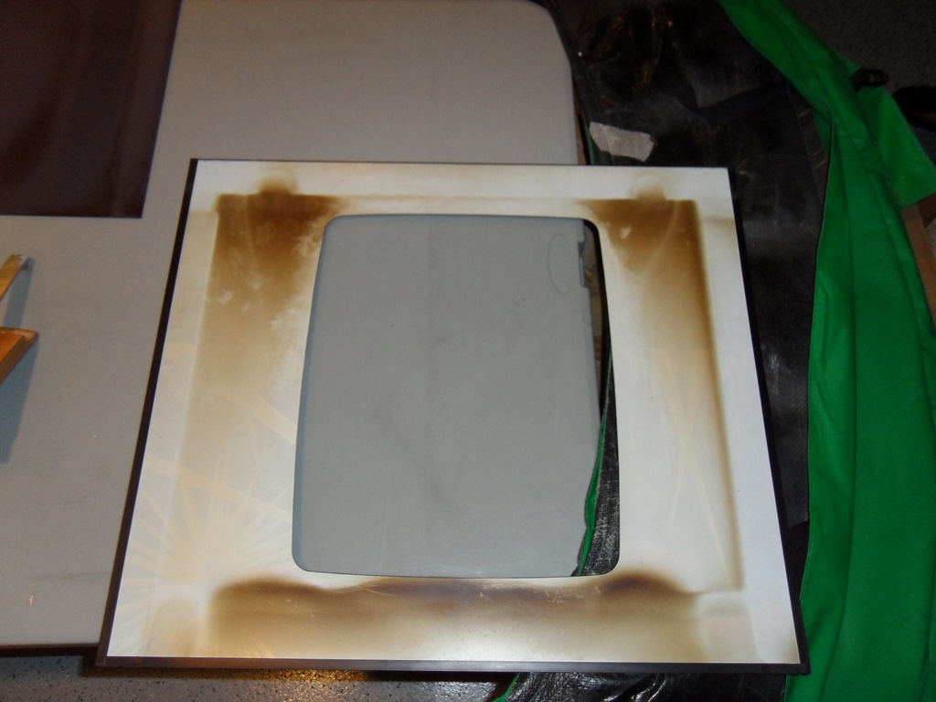
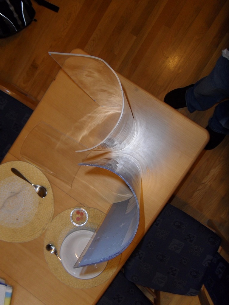
The Sea Scare manual shows a smoked plexi of the style in Astro Wars but the one that's in there is a different shape and has a different tint than Astro Wars. I can't determine if it's because the Sea Scare one was replaced or it left the factory with it. Astro Wars also appears to have screw holes in the plexi so that it doesn't slide out of place as it did in the Sea Scare cabinet.


|
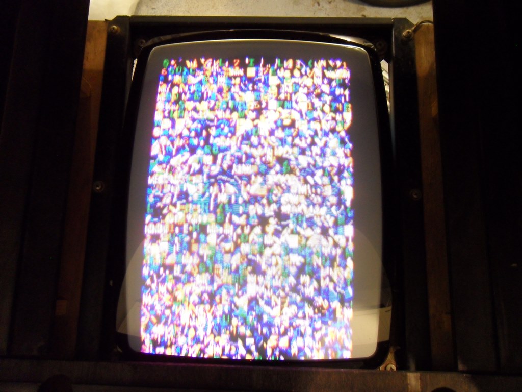
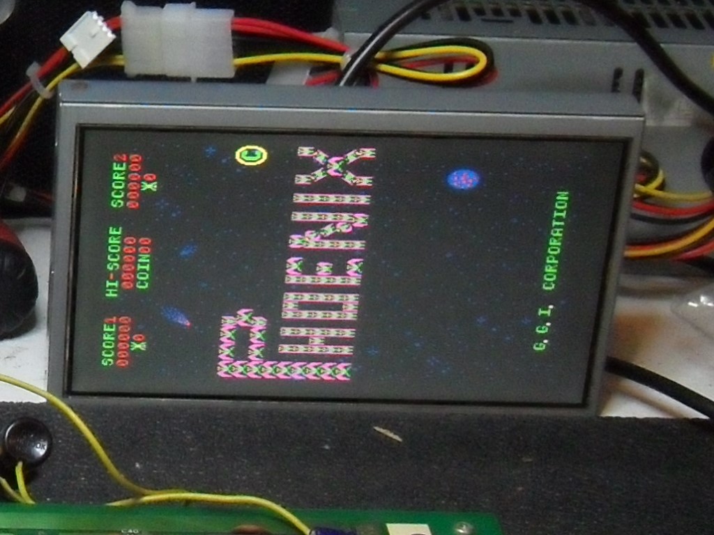
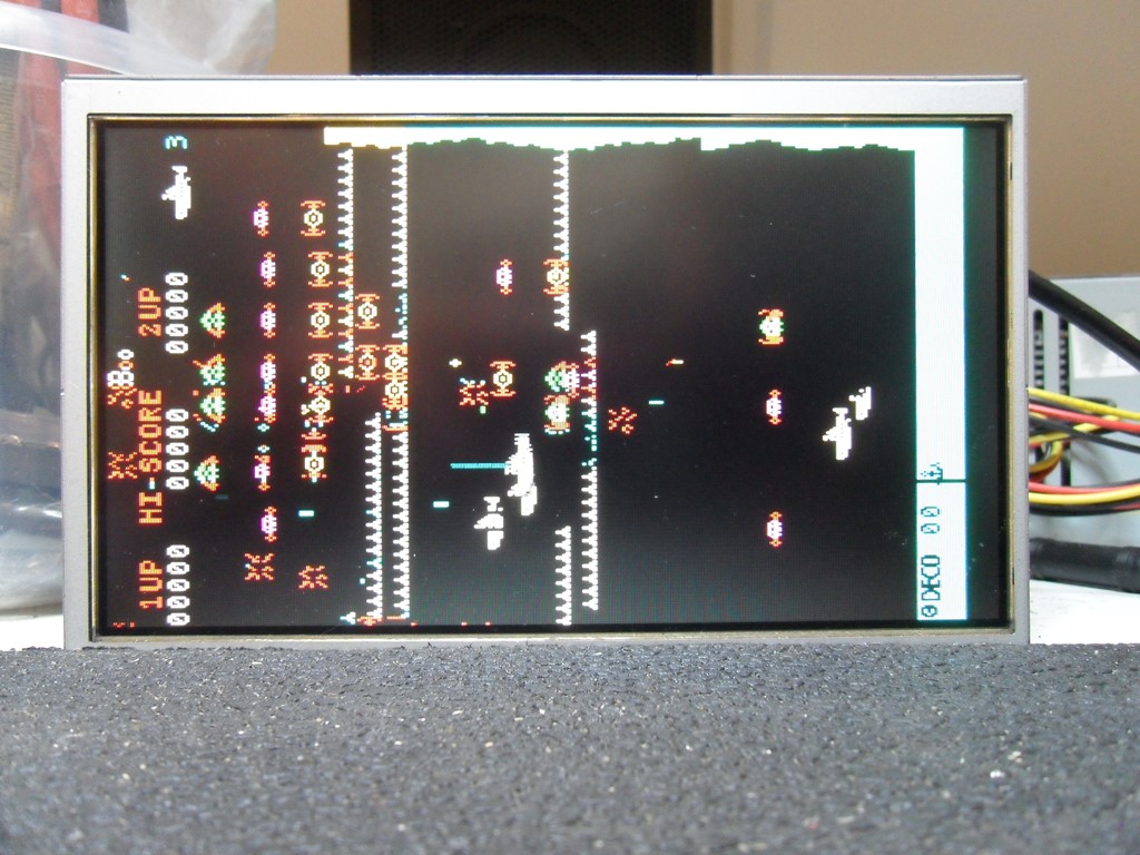
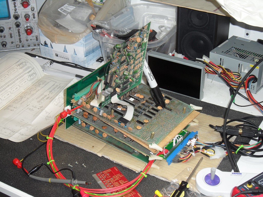
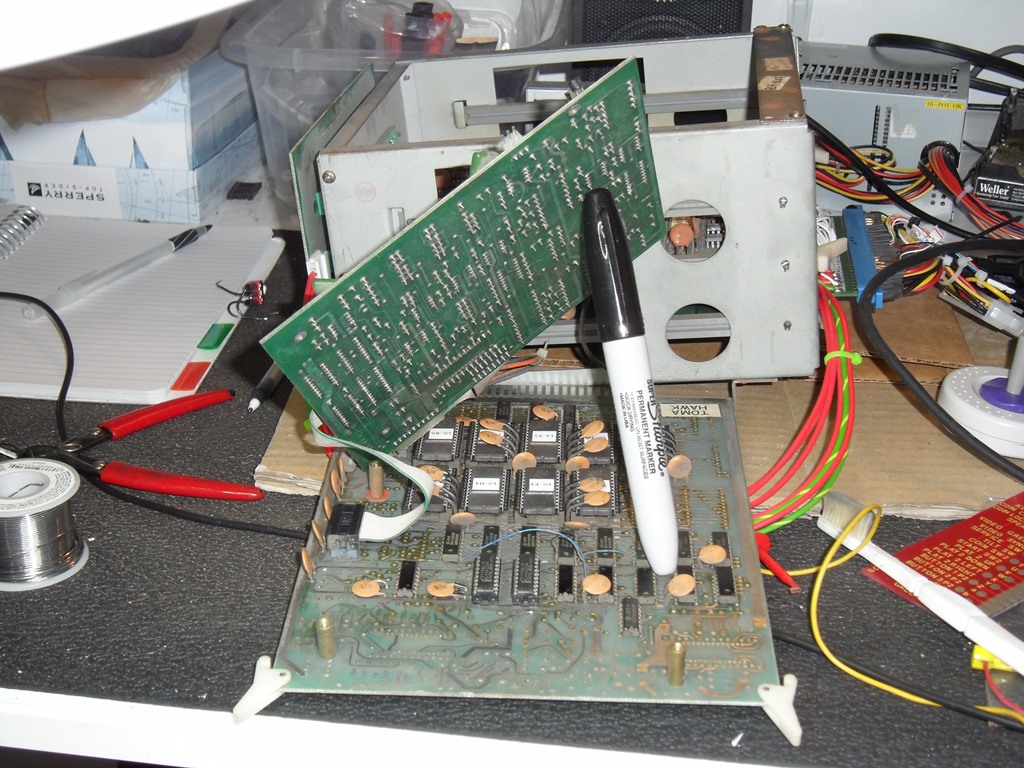
On the bench the Phoenix game PCB still show no signs of life. Scoping out the 8085 suggested the CPU wasn't doing anything. Even with a pulse injector on the reset line there was no activity on the AD bus at all. Didn't see any initial activity on power on either. A replacement 8085 brought the game to life though some of the sounds seem off and the colours don't look quite right. It also looks like a standard GGI Phoenix game with nothing related to the Firebird marque. For now it's enough to check out the monitor a bit more.

|
The MTC-90 picture was still soft even with the focus max'd out. Adjusting the brightness or RGB pots caused bleed with only moderate brightness. Adjusting anything from the as-supplied settings made it worse and in the end I needed to refer back to a prior photo to reset all the pots back to what they were to get the best picture out of it, but still far from decent.

|
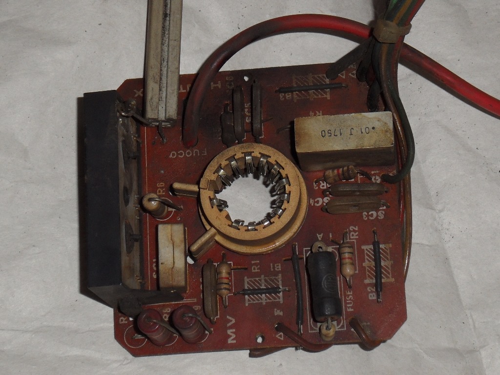
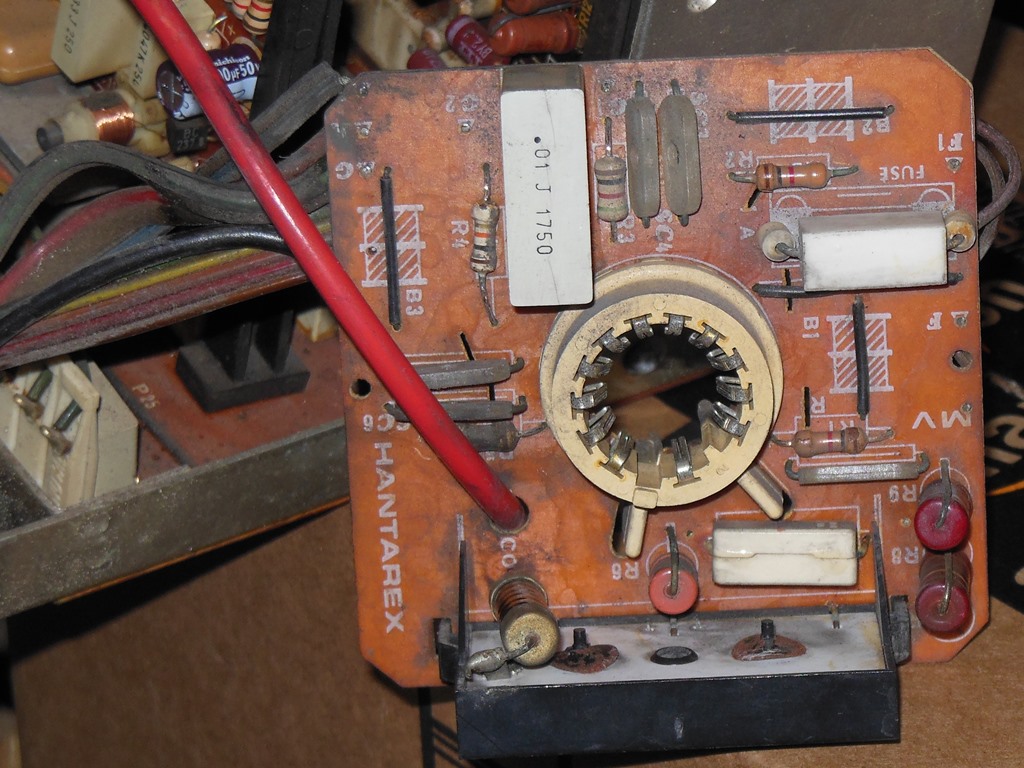
Experimented a bit with the Sea Scare focus circuit and the focus would pull in a bit more with one of the resistors in the focus chain bypassed. After consulting with fellow collector it we think the large 2.2K Ohm resistor is some sort of unofficial modification. It's a bit nuts to have a large power resistor at a few thousand volts hanging off the back of the neck PCB. The manual has a schematic that doesn't match the neck board and it doesn't show this component on it. To confirm what should be there I pulled a broken MTC-90 out of one of the DoL Astro Wars and found something else in that location...


|
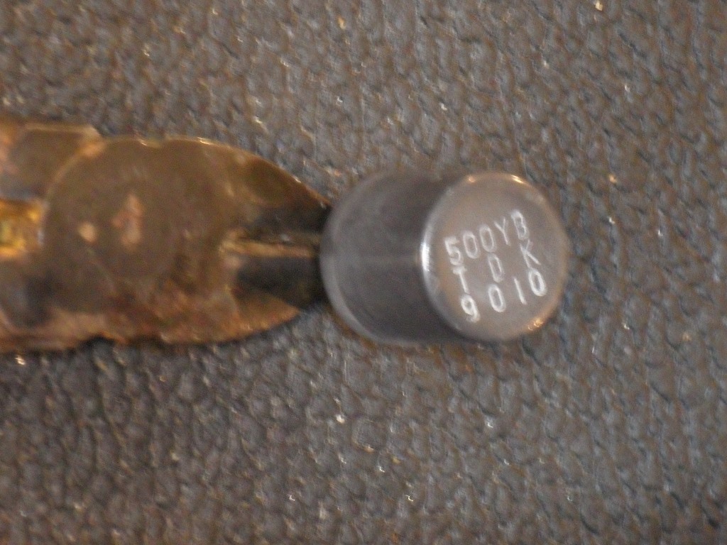
The actual component that should be there is marked as "VTM 175 3.3KV 10%". The meter measures 7M Ohm accross it in circuit. Clearly nothing like the 2.2K Ohm on the Sea Scare chassis. Getting a bad feeling, I replaced the neck board with the Astro Wars one. The bad feeling was confirmed - the focus spark gap lit up and focus pot arced out :( My current theory is that the tripler is shot and some tech hacked part of the focus circuit to pull down the focus voltage. Next step is to order a new tripler (spares do exist).
|
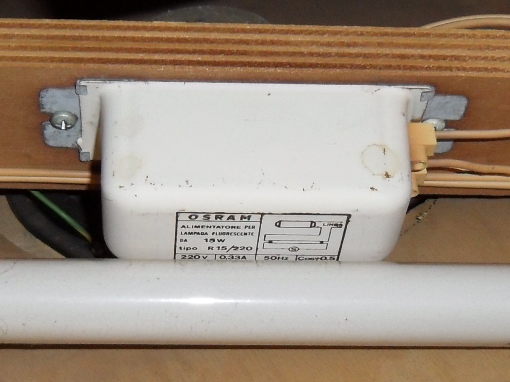
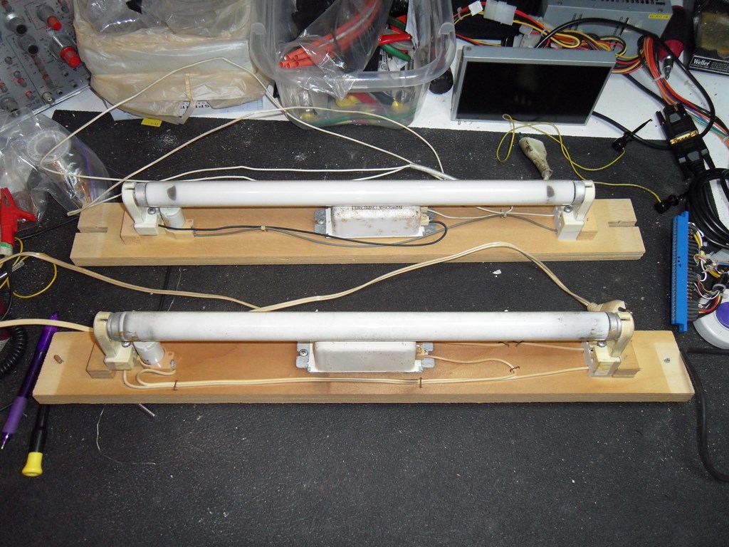
The ballast on the marque light is faulty and the starter socket broken so both of those were transplanted from a fixture out of one of the DoL Astro Wars. Marque light fixed :)

|
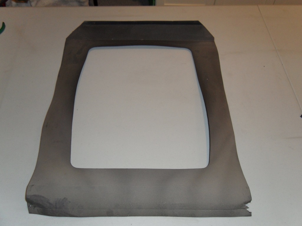
The monitor surround was in pretty good condition and cleaned up OK. It just needed some stiffening and a couple of repair pieces around the staple area. Glued and left to set for a few days.
|
The monitor surround dried without issue and was stapled back into the cab. The back portion is stretched/deformed a little by the monitor frame sticking out a but it looks like it left the factory like that. The question over whether this cab had the same smoked plexi as Astro Wars wasn't really resolved - the part code in the manuals are the same. The tint is lighter and a different colour on the one that was in the cab versus Astro Wars so I decided to keep the one it arrived with. A lot of elbow grease removed the nicotine stains.

|
I used the Astro Wars plexi as a template to drill two screw holes to keep the plexi in place. The holes are only slightly smaller than the screw so the screw sits near flush with the plexi. It should be well short of contacting the glass art but just in case I covered them with a small square of tape. With the glass fitted it looks pretty good. It'll be interesting to see how Tomahawk 777 looks with this light tint plexi.
|
I decided to take a chance and replace the suspect tripler with the unknown one from the broken chassis. The blue wire was routed slightly differently between the two but electrically the same (as I found out because the blue wire was too short to reach the same pad as the white one). Initial power on yielded no sparks and a picture :)
|
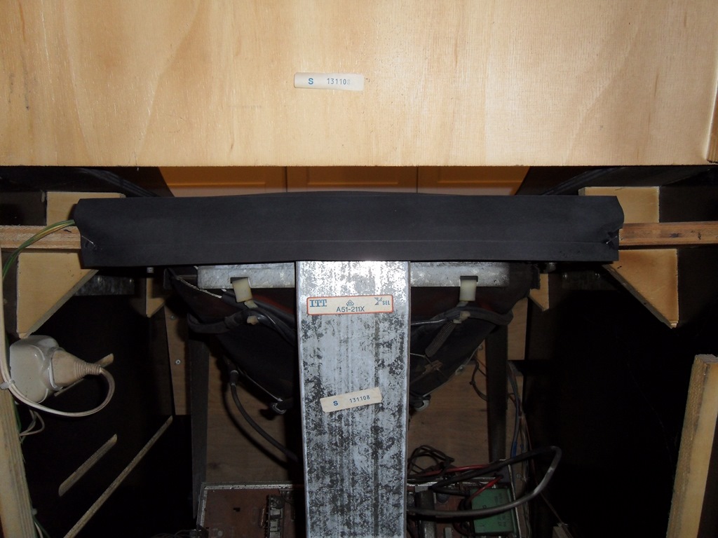
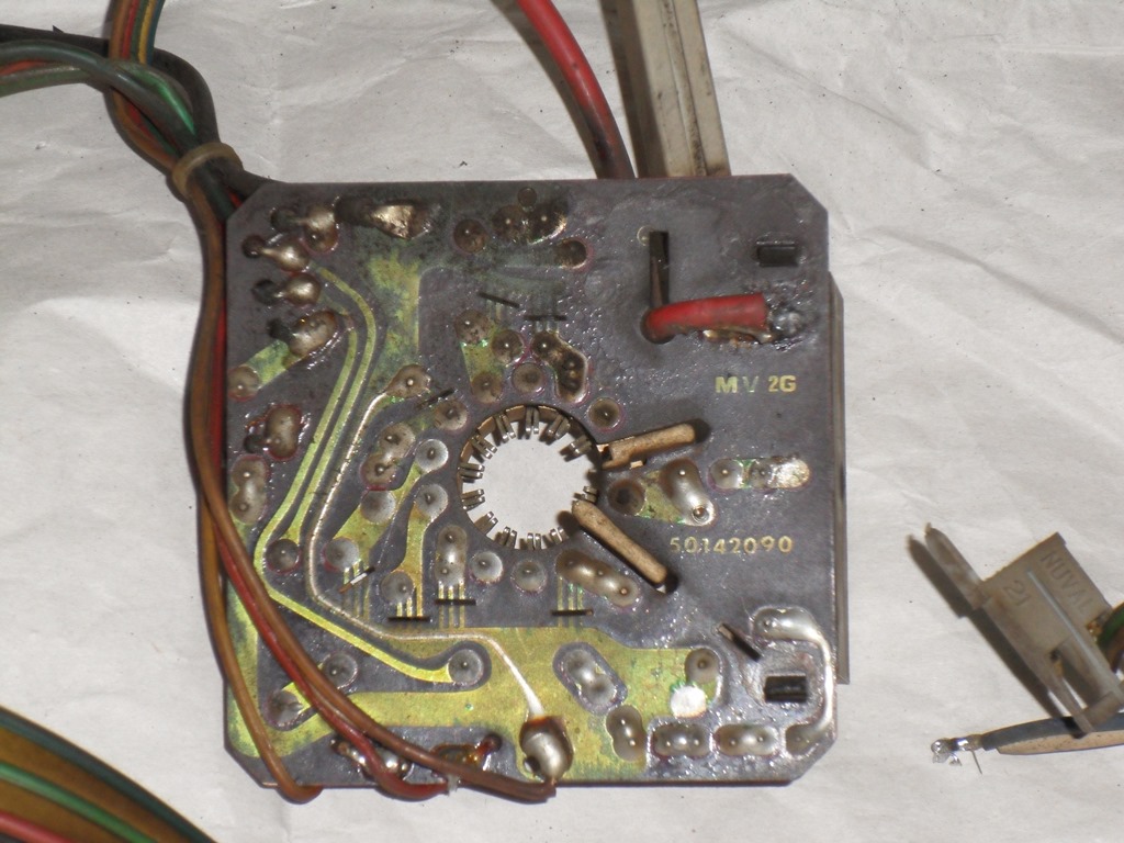
The neck PCB revision (MV 2G, 50142090) and configuration for ITT A51-211X CRT for future identification reference.
|
The focus adjustment worked as it should and it pulled in reasonably OK. Green is still a bit fuzzy and the degauss was a little off. The colours don't seem right and the plexi seems to have tinted the whites a bit. The monitor manual suggests that the monitor has TTL input but I'm not sure yet if it's really configured this way.


|


|
Scanned in the Sea Scare monitor glass.
300 DPI Sea Scare monitor glass scan (19.7MB).


|
Scanned in the Sea Scare control panel overlay.
400 DPI Sea Scare control panel overlay scan (11.8MB).


|
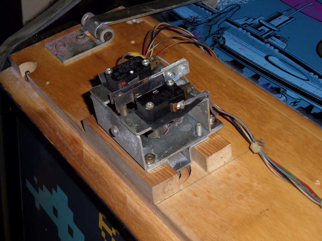
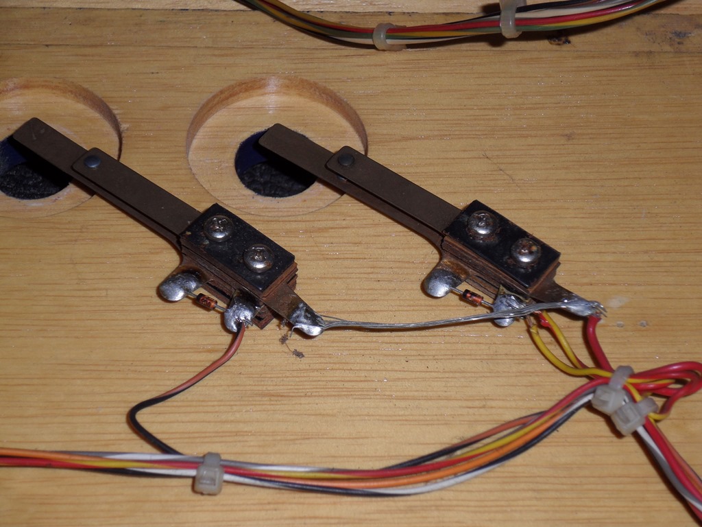
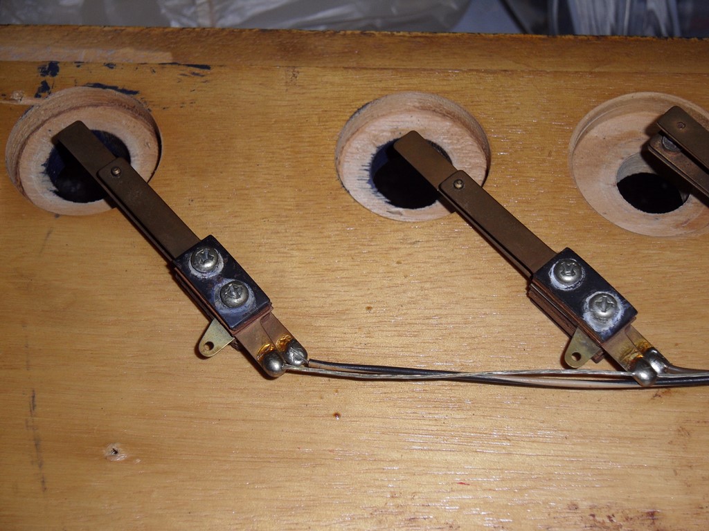
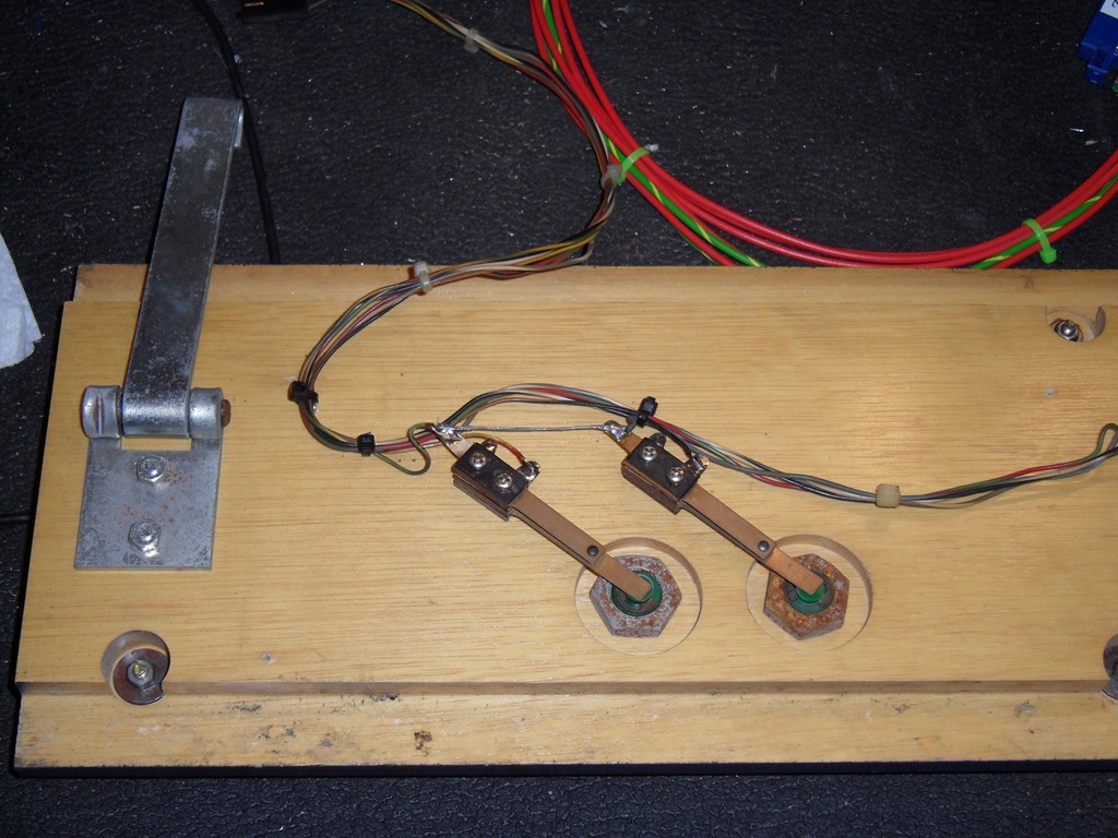
Cleaned and polished the replacement control panel from a DoL Astro Wars (and also confirmed the holes lined up with the overlay of course). Kept two of the leafs from it and moved the Sea Scare control panel wiring & leafs over to it, connecting up the two direction leafs left in place. The final step was to apply new staples and cable tie the wiring in place.

|
During the wiring change over I noted that the Sea Scare leafs are different and don't contain the matrix diode tab that's needed for Astro Wars. The finished restore looks good but of course the control panel overlay is still damaged. Now scanned, in future it should be possible to restore the artwork and reproduce a whole replacement for it.
|
|


|
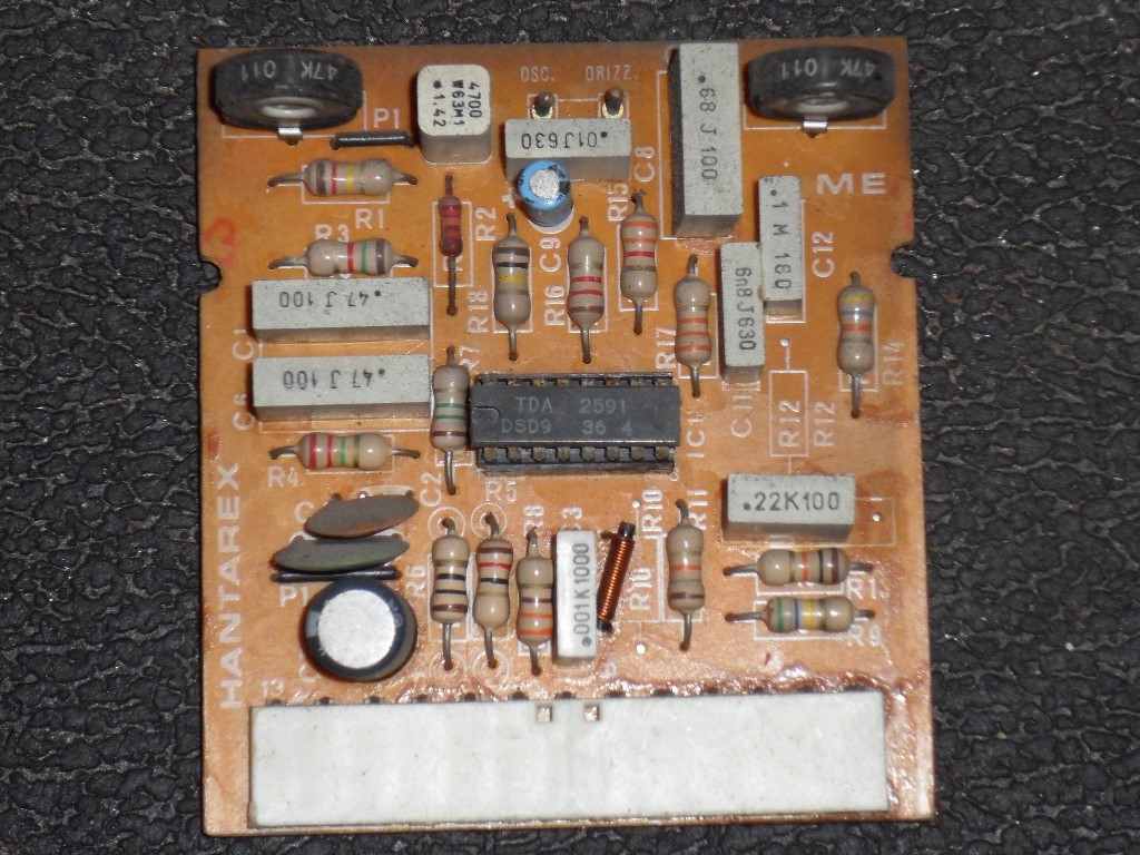
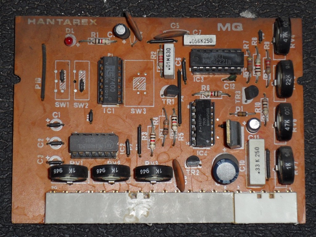
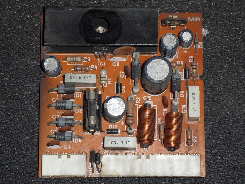
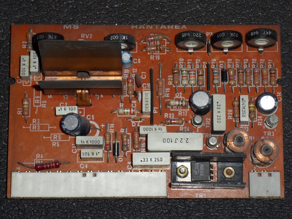
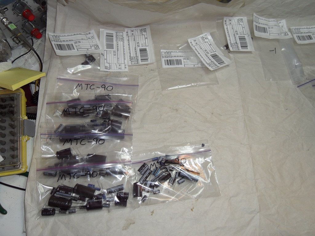
Pulled out all the little boards from the broken MTC-90 chassis to catalogue the caps in order to make up some cap kits for it. There are also caps on the two mother board panels (not show). On this one a few caps were leaking and burst. Bob doesn't carry made up kits for this chassis so I'll need to make my own this time.
| PMW | PMK | MS | MR* | ||||
|---|---|---|---|---|---|---|---|
| Location | Value | Location | Value | Location | Value | Location | Value |
|
C1 C2 C3 |
not used 470uF @ 16V 47uF @ 350V (250V) |
C5 C14 C15 C16 C17 |
470uF @ 250V BB 1000uF @ 25V (2200uF @ 40V)** 1000uF @ 16V 2200uF @ 40V 47uF @ 160V |
C5 C6 C10 C14 |
100uF @ 25V 22uF @ 16V 47uF @ 25V 100uF @ 16V |
C10 C11 C11 C12 C13 |
(C10) 470uF @ 16V (C11) 100uF @ 25V (C13) 47uF @ 35V (C12) 470uF @ 35V (C14) 1uF @ 350V (160V) |
* The silk screen on this board is incorrect
- values in brackets indicate the manual parts listing.
** Manual listing for PMK-C14 likely a typo.
| MQ | MD | ME | MP*** | ||||
|---|---|---|---|---|---|---|---|
| Location | Value | Location | Value | Location | Value | Location | Value |
|
C9 C11 C13 |
47uF @ 25V 10uF @ 16V 10uF @ 16V |
C12 |
47uF @ 16V |
C5 C9 |
100uF @ 16V 4.7uF @ 35V (16V) |
C1 C2 C5 C6 C7 C10 C12 |
47uF @ 16V 100uF @ 16V 47uF @ 16V 47uF @ 16V 47uF @ 16V 47uF @ 16V 47uF @ 16V |
*** MP board is not documented in the manual.
MU and MT do not use any electrolytic capacitors. Collapsing into common higher voltages yields the following parts list for 10 cap kits and with the bulk discounting costs in at ~$14 per kit excluding the $5 big blue. Note that there are cheaper series than PW but this series has a long lifetime and 105 degree temperature rating for most values.
| Quantity (29) | Value | Locations | DigiKey Parts |
|---|---|---|---|
|
1 1 2 1 10 2 5 3 1 2 1 |
1uF @ 350V 4.7uF @ 35V 10uF @ 16V 22uF @ 16V 47uF @ 35V 47uF @ 250V 100uF @ 25V 470uF @ 35V 470uF @ 250V BB 1000uF @ 25V 2200uF @ 40V |
MR-C13 ME-C9 MQ-C11-C13 MS-C6 MS-C10,MR-C11,MQ-C9,MD-C12, MP-C1-C5-C6-C7-C10-C12 PMW-C3,PMK-C17 MS-C5-C14,MR-C11,ME-C5,MP-C2 PMW-C2,MR-C10-C12 PMK-C5 PMK-C14-C15 PMK-C16 |
493-2055-ND (400V, PW) @ 0.46 (10) 493-1889-ND (50V, PW) @ 0.29 (10) 493-1809-ND (25V, PW) @ 0.30 (20) 493-1811-ND (25V, PW) @ 0.30 (10) 493-1896-ND (50V, PW) @ 0.36 (40) 493-2025-ND (250V, PW) @ 1.31 (20) 493-1899-ND (50V, PW) @ 0.46 (40) 493-1911-ND (50V, PW) @ 0.88 (30) 493-2030-ND (250V, PW) @ 4.85 (10) 493-1832-ND (25V, PW) @ 0.82 (10) 493-1923-ND (50V, PW) @ 2.48 (20) |

|
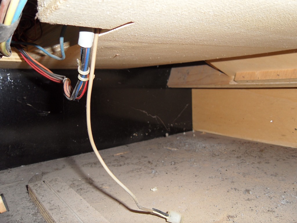
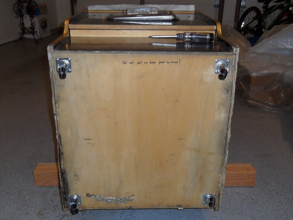
As noted earlier the pedestal base was missing and no feet were on the cab so as a result the cab had been resting on the side walls. The base is attached by slotting into the side walls with glue but due to the lack of feet the side walls have disintegrated up to the base and the base has separated from the side walls in places. Inside the cab there is no reinforcement of the base to the walls :( There is only a narrow gap between the power supply plinth and back wall with which to gain access to the base cavity - my arms just fit through enough to reach to the front and not enough maneuvering room to get any tools or a drill in. Not enough space to get light in or see anything inside. The plan here was to strap the base together and glue in some wood pieces to hold the base and walls together. The camera proved invaluable for "seeing" the cavity.

|
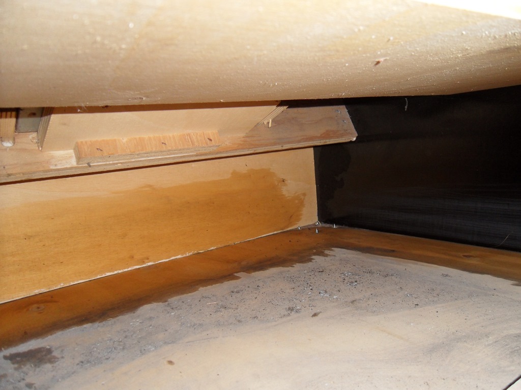
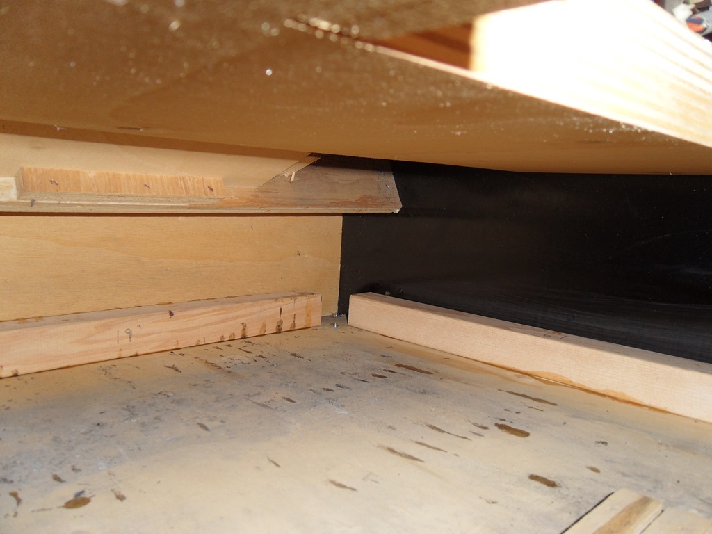
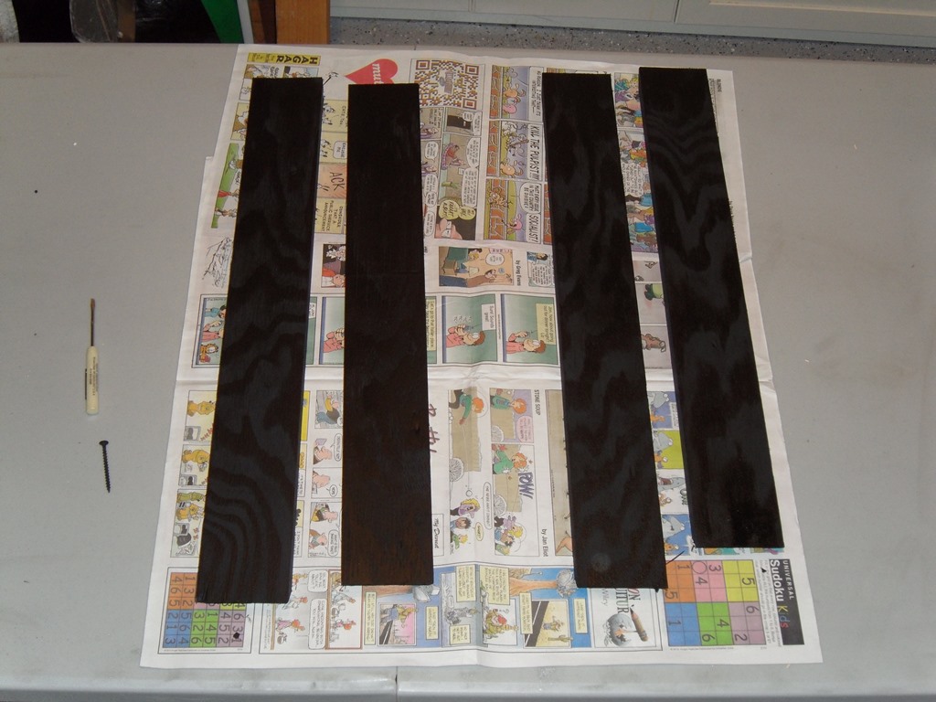
Only able to get my arm in to the elbow I could only reach the permitted of the cavity but it was enough to be able to clean off the dirt and sand down the areas to be glued. The three pieces to fit are all 19 inches long leaving a small gap at the ends where the screws from the castors break through (something I didn't think of until I saw the pictures). The back has the card cage and is undamaged so the pieces will go on the right, left and front walls.

|
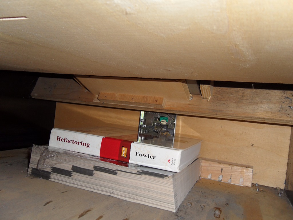
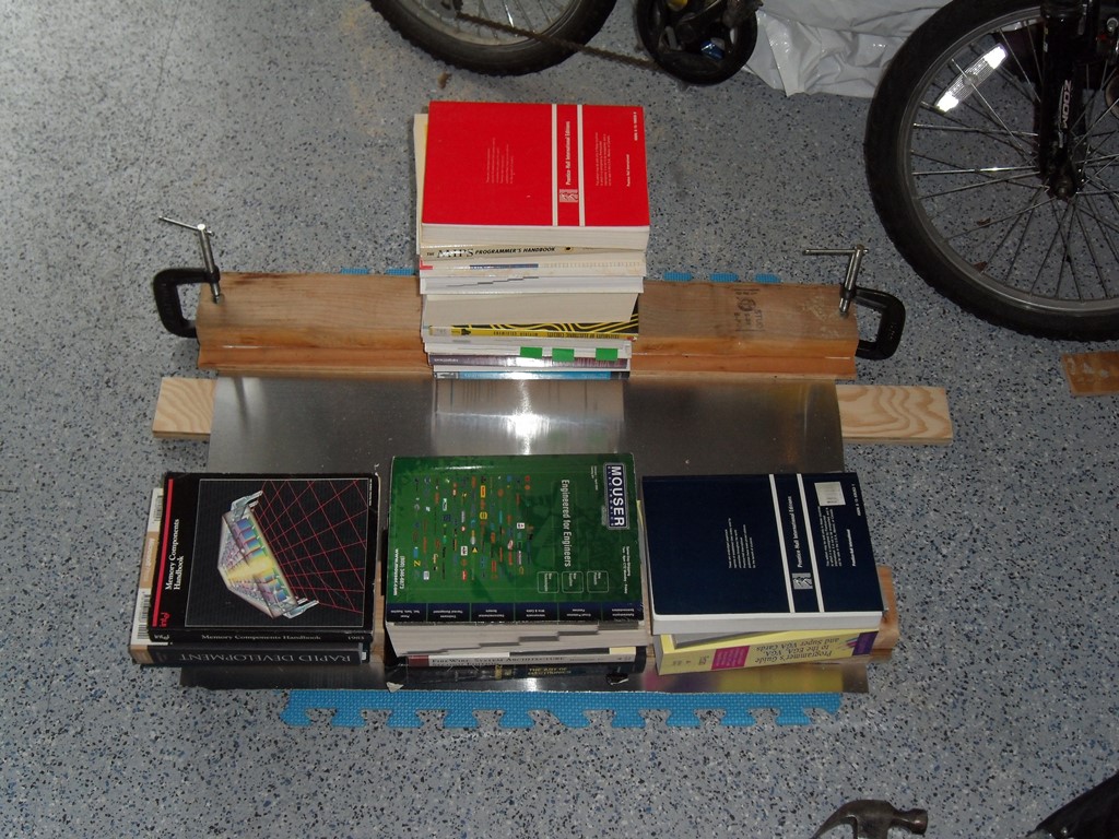
Ratchet strapped the bottom of cab to hold it together tight, glued the pieces and managed to get them in place (did the front on day 1 and the two sides on day 2). With such limited space the best I could come up with to keep the wood in place whilst it set was heavy books for the sides and tools on the top.

|
As far as I can tell so far it turned out OK :)
|
The caps arrived from DigiKey and were assembled into 5 kits. After fitting one to the Sea Scare chassis the picture looked a bit better. I won't try tweaking it again until a T777 board set is in it.

|
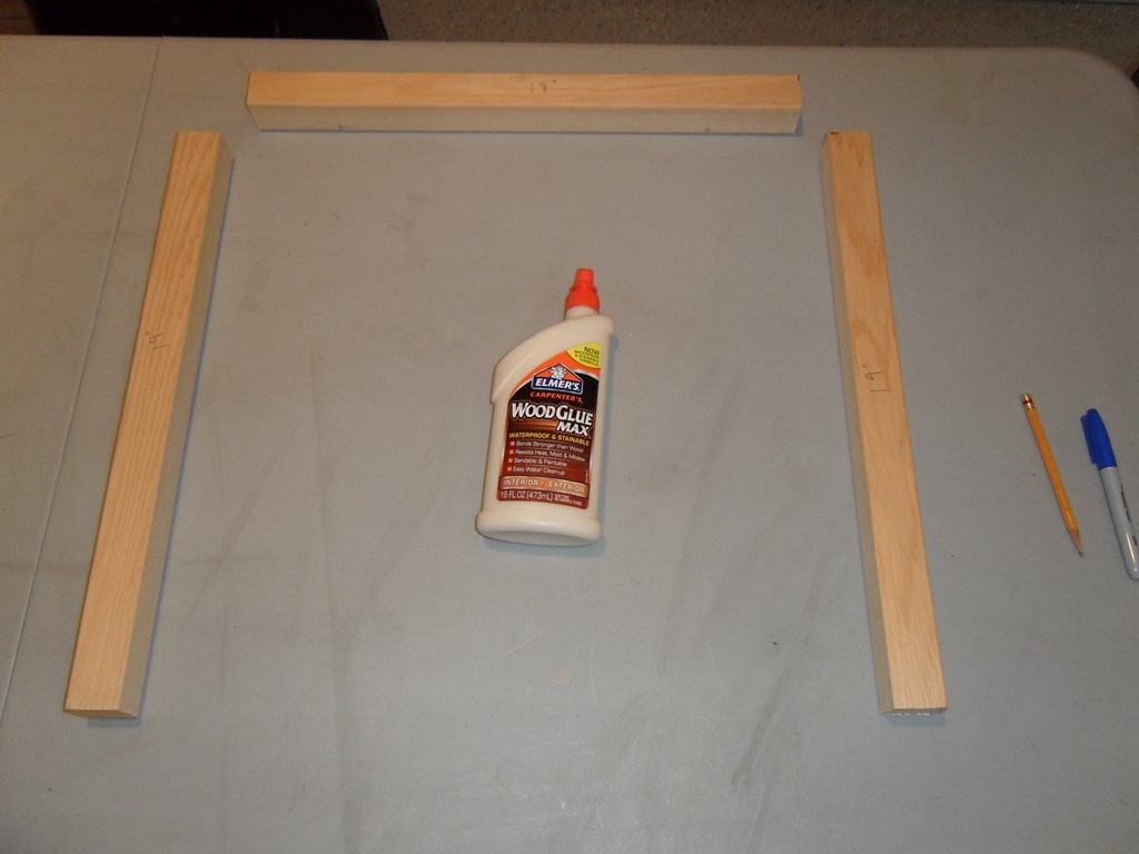
Since the base on Sea Scare was completely missing I used the Astro Wars base as a reference for repro'ing a base. I also bought myself miter saw from Home Depot - how have I managed this far without one???

|
I decided not to triangle the base mounts so as to leave better support for the castors.
|
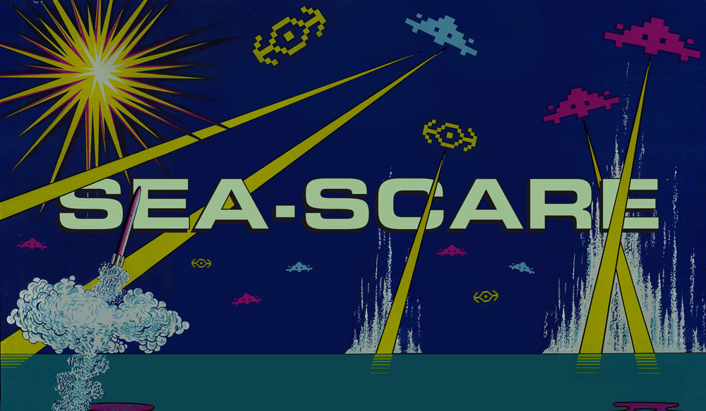
ChrisChris from the Dragons Lair Fans forum volunteered to invent and create a marque. Since no photos of this cab or flyer had been found we came up with something based on the existing style and artwork of the cab.
|
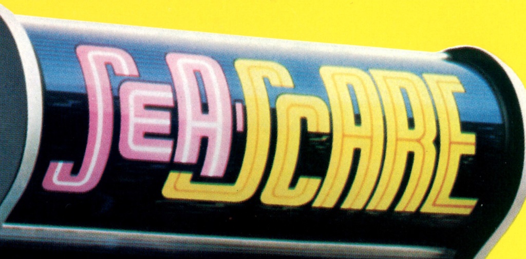
ChrisChris discovered a Zaccaria Sea Scare flyer in a haul of flyers from an operator!
|
Now we can see what the "real" marque should look like.
|

|
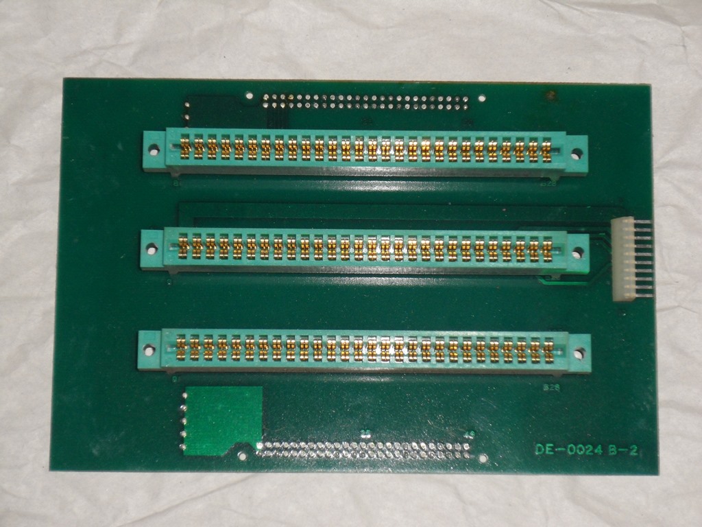
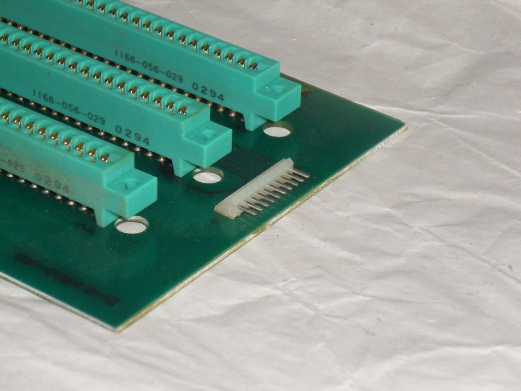
First order of business was to identify the backplane power connector. Thanks to Craig W., confirmed as a JST NH series connector and available from giz10p.co.uk. The Astro Fighter and Tomahawk 777 board sets line up as follows:
| Board | Zaccaria Sea Scare Manual | Gremlin/Sega Astro Fighter Manual | DECO Astro Fighter UP-5 Manual |
|---|---|---|---|
| Mother Board | DE-0024 | not listed | DE-0024/DE-1024 |
| I/O Control Board | DE-0025 | DE-0025/DE-1025 | DE-0025/DE-1025 |
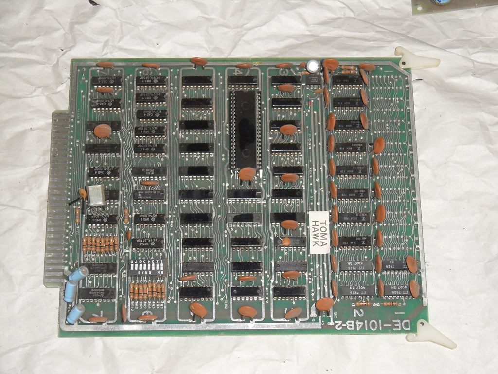
| CPU Display Board | DE-0014 | DE-0014-4 | DE-0014/DE-1014 |
| ROM Board | DE-0022 | DE-0022-3 | DE-0022-2/DE-1022-3 |
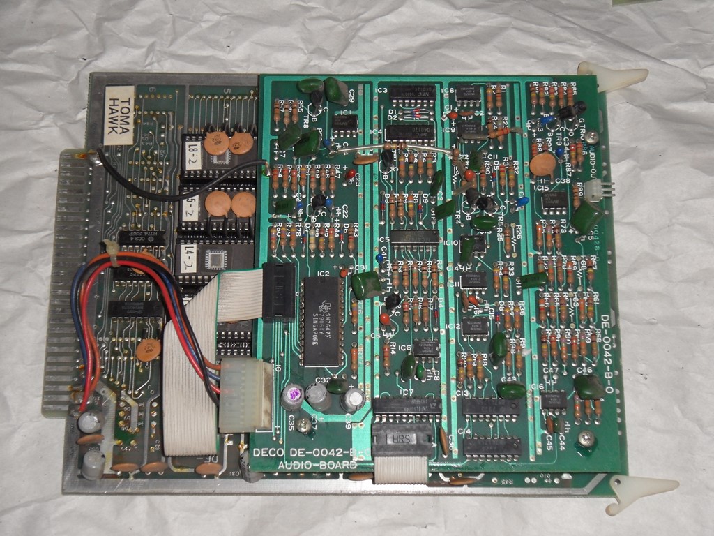
| Audio Board | DE-0042 | DE-0038 | not listed |
| Power Amplifier | DE-0043-0 | n/a | n/a |
From the part codes in the manuals it looks like T777 shares all the same boards as Astro Fighter except for the audio board and the external audio amplifier board. I found some posts on the web, however, that notes Sega versions are not compatible with the Data East versions. They also have a different pinout from the Data East versions (DECO IO DE-0025 versus Sega IO DE-1025). Some further research needed :(

|
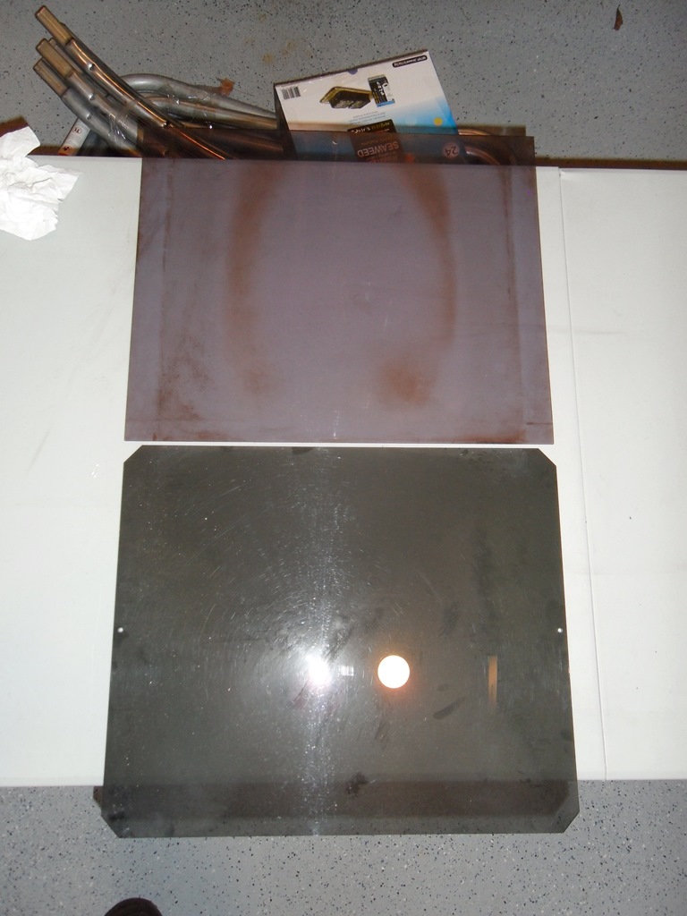
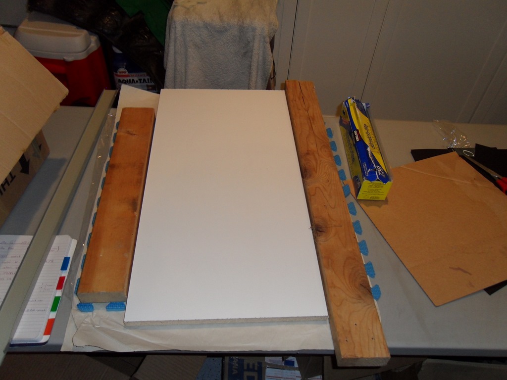
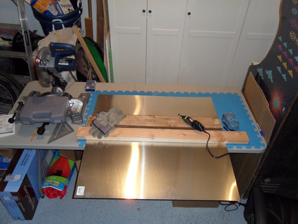
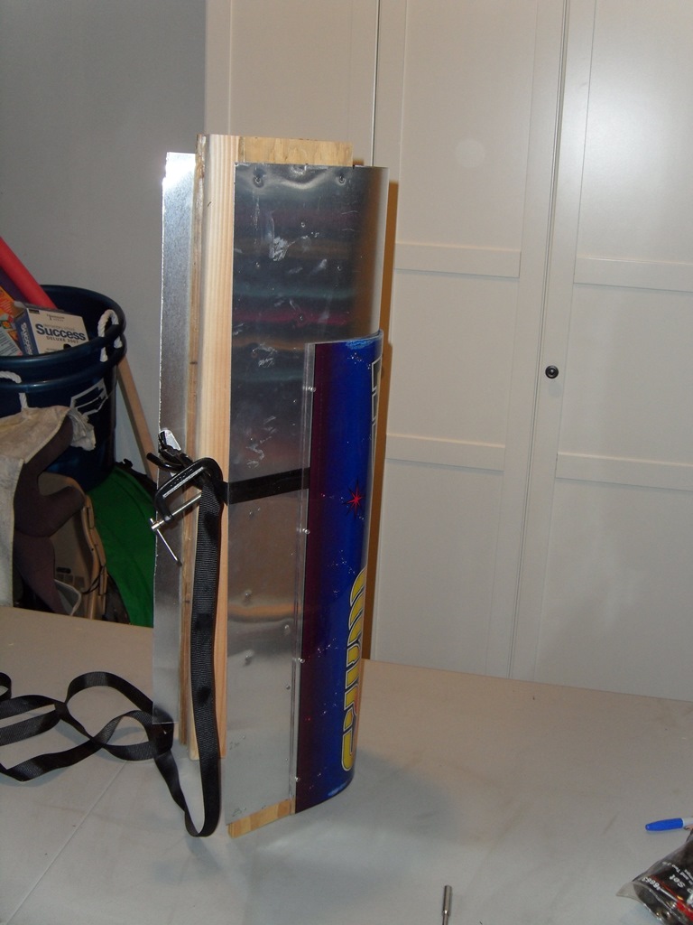
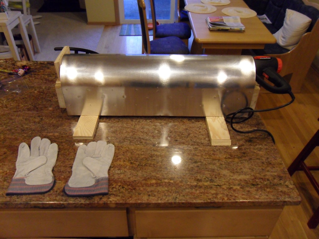
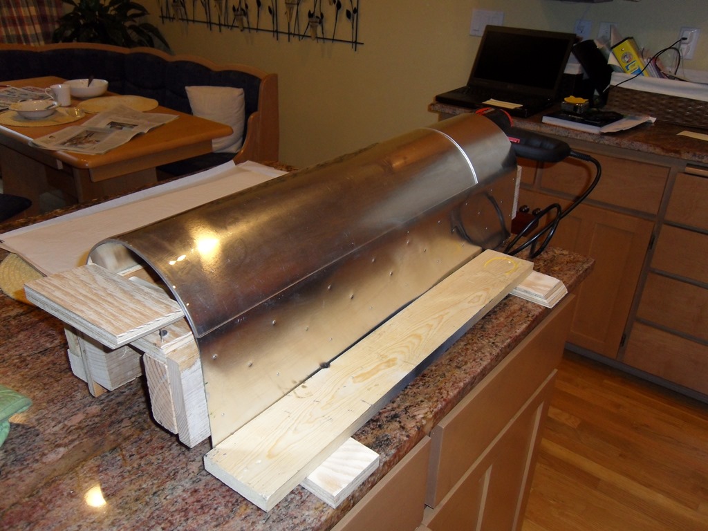
To curve the acrylic marque I decided to make a curved aluminuim mold from a sheet of aluminium plate. The base sheet I cut oversize and marked the outline of the flat marque and then where the straight edges border the curve. To keep the straight edges from curving out I tacked and glued on a couple of wood planks to the back of the plate. On the back of that I glued on 2 x 4's for further bracing.

|
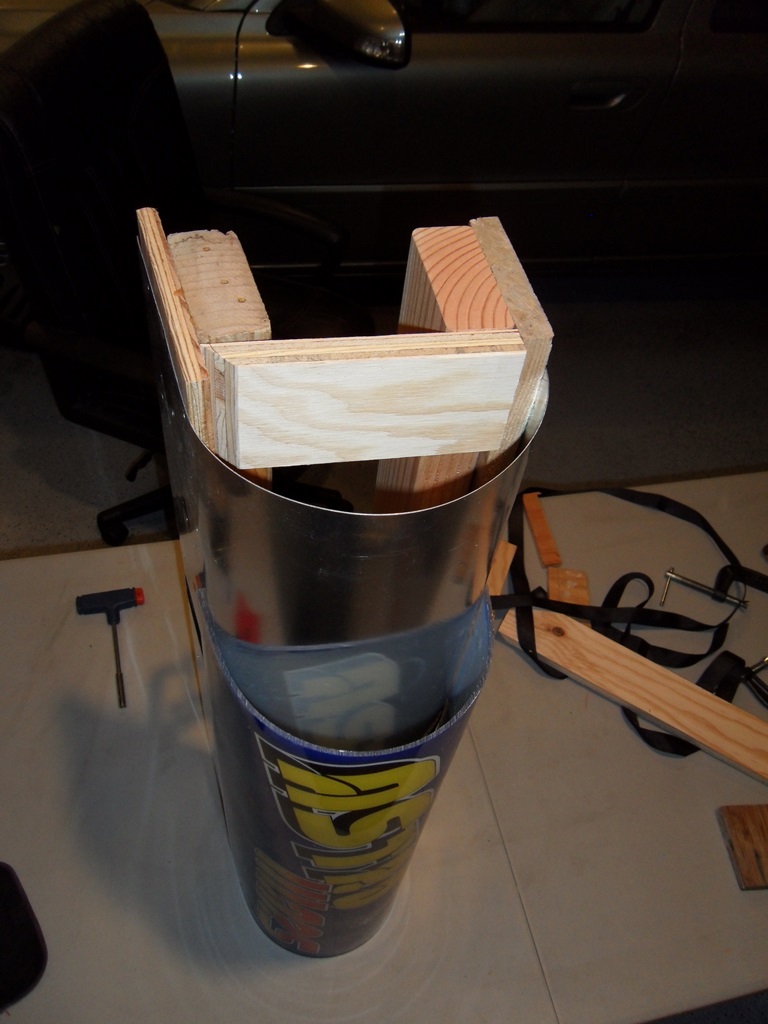
Using a ratchet strap I pulled the ends of the plate together until it matched the Astro Wars marque in terms of end-to-end height. Though the measurements were pretty much spot on, the arc of the curve (that depends on the characteristics of the aluminuim plate) ended up too a bit too sharp. To correct for that I used a couple of shims to spread the curve a little bit to make it shallower.

|
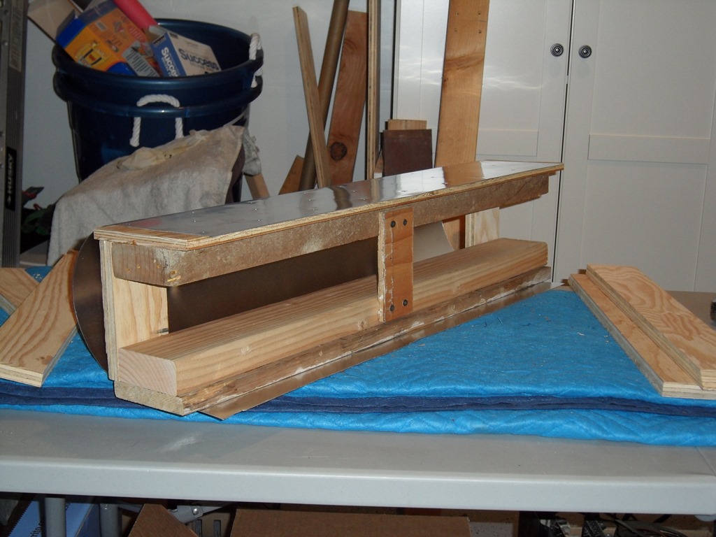
With the curve and shims set the mold was fixed in place with a scrap peice of wood and a few screws. The last step was to add a wood strip to set the start of the long edge of the marque.

|
Refitted and secured the PCB card guides that had fallen off in transit and then placed it in the cab. The Astro Fighter cage didn't fit the Sea Scare woodwork as is but the frame has a number of additional holes. To fit properly in the Sea Scare cab the lip bracket needed moving up one hole.


|
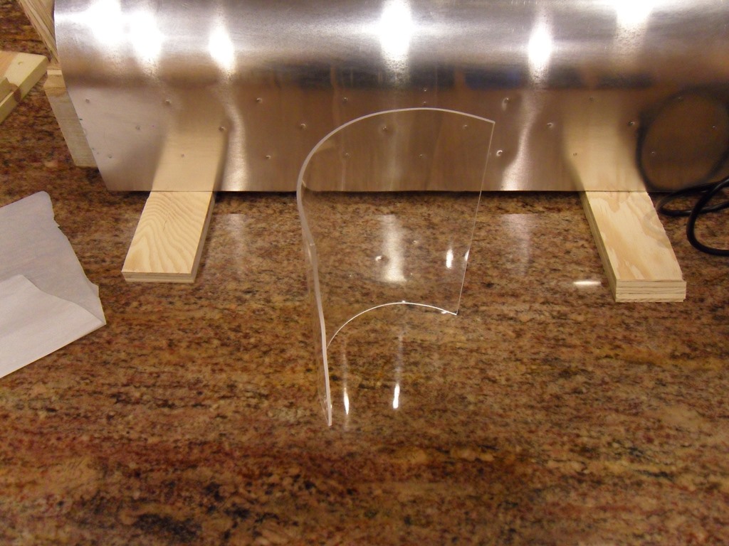
The first attempt was based on using a heat gun under the mold to heat the mold itself so that the acrylic gradually formed over it as it softened due to the heat. On the first attempt the heat was too high and it burned the sample on contact. On the second attempt the acrylic began to form.

|
It took a very long time to only slightly form and it didn't look like it was going to work this way with a full sheet :(
|
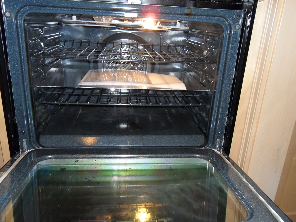
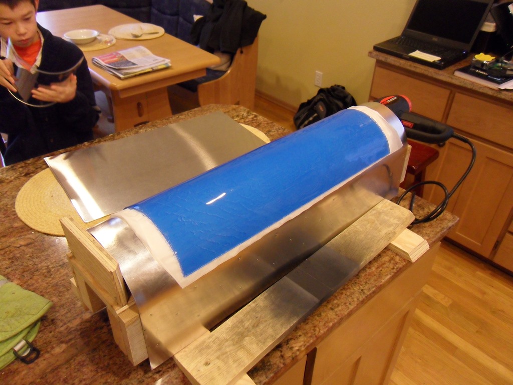
The second attempt was based on oven heating the sheet and forming in one on a pre-heated mold. The mold heating was only intended to prevent immediate cooling as a way to buy some positioning time. After 15 minutes at 250 degrees the sample was pliable but firm though it did form reasonably well. It's worth noting the TAP guide explicitly states that acrylic should never be heated in a kitchen oven due to the release of explosive gasses if overheated. We have a GE Monogram that has digital temperature setting, fan assist and a 3rd heating element behind the fan. I didn't use the conventional top or bottom in-compartment heating elements for this project and relied only on the fan heater.

|
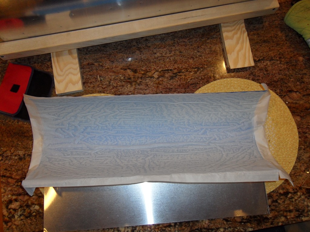
For the third attempt we tried a full size sheet going for a production marque. Since the sample was still stiff and the data sheet showed a minimum of 290 degrees for full forming I decided to go with a higher temperature of 275 degrees and a longer time given the larger sheet size. I peeled off one side of the protector based on the advice of the TAP guy and kept the inner arc side on to keep the mold side protected. The sheet was baked on parchment paper on a "cookie sheet" made out of some of the left over aluminium plate.
|
The first production marque had some issues. The protective backing had melted making it both hard to remove and caused texturing on the mold side :( The actual shape itself came out reasonably well though not perfect.
|
With both protective sheets removed the second production marque came out much better but still with a small amount of surface texturing from the parchment paper but it's not too noticable with artwork behind. I ran out of time to try the third (and last) flat - the third one I'll bake directly on the sheet with no parchment paper. I'll continue on with the second production marque for the time being.
|
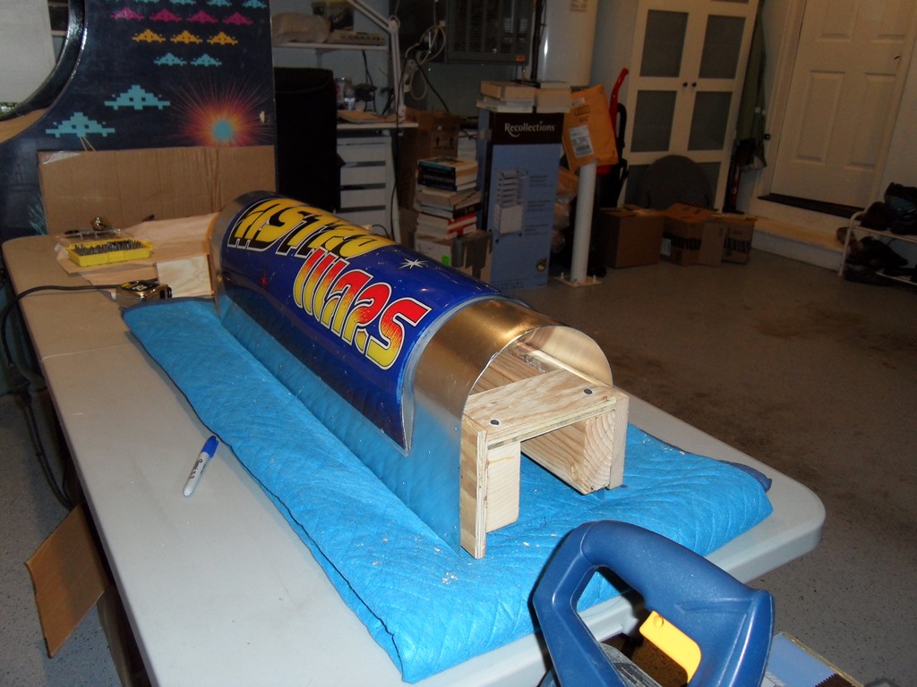
Astro Wars behind the the second production marque looking not too bad.
|
My son made temporary marque artwork and I drilled the mounting holes and fitted it. No issues with the fitting - fitted perfectly.
|
The third production marque was based on baking directly on the aluminium sheet with no paper as a correction for the surface texturing from the parchment paper. Alas, this attempt was an unexpected failure :( Couple of issues, the first being that the sheet didn't breath so vapours ended up trapped and texturing the surface like a "watermark". The second was that the perspex stuck to the aluminium sheet and thus ended up slightly deformed when peeled off. On the plus side, the none watermark areas were perfect and the shape molding was near perfect. I don't have any further ideas for getting a good bake - the data sheet for the perspex recommends hanging the sheet so that it doesn't touch anything but it's awkward to set that up in a kitchen oven. If I did it again, I'd try 250 degrees as a compromise between hot enough to mold but cool enough to reduce the vapour release. For now, the second production marque is good enough to use. Moving on...
|
The power connectors arrived from giz10p.co.uk enabling me to build a JAMMA adaptor. I based it off the Zaccaria Sea Scare manual for the Tomahawk 777 configuration. I didn't sort out the sound or the NO/NC coin input yet, video and attract mode is enough to get started. Looks like I have two working sets to work with for now.
|
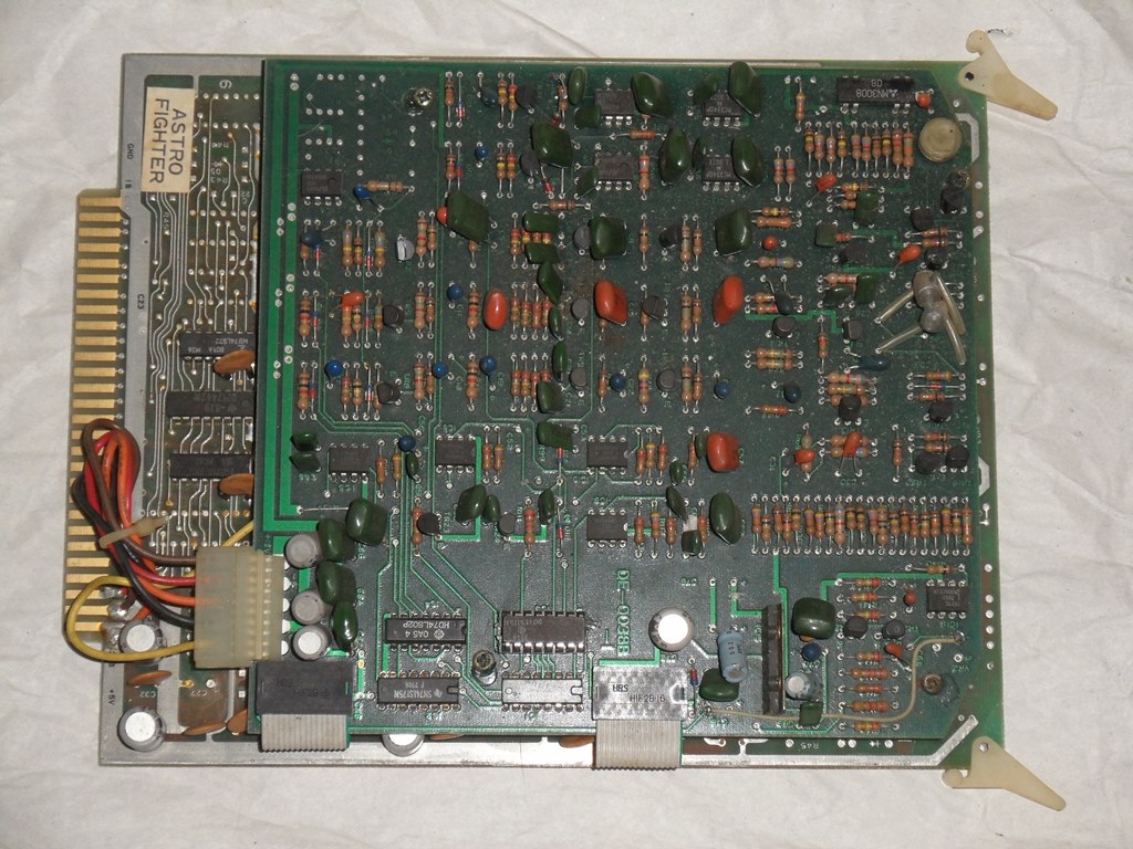
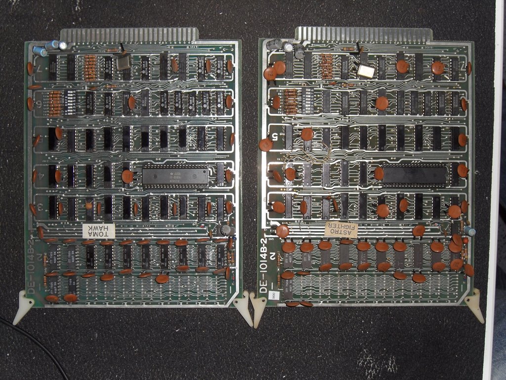
To convert the Astro Fighter boards needs a new EPROM set and a new colour PROM at least. To start with I removed the Astro Fighter specific sound board that won't be needed for T777 and fitted sockets. The second board set is flipped with blue background.
|

|
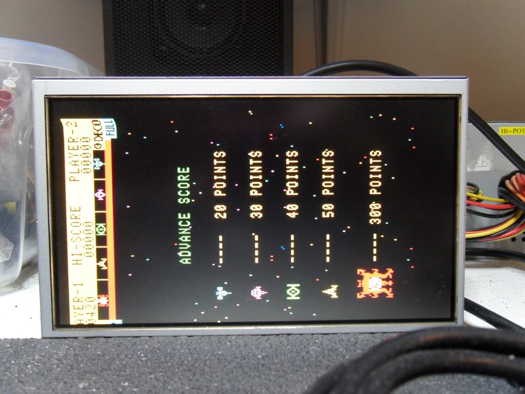
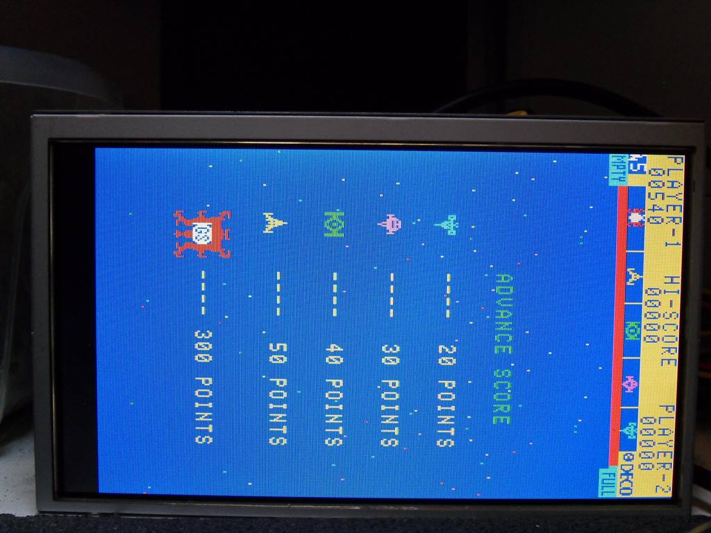
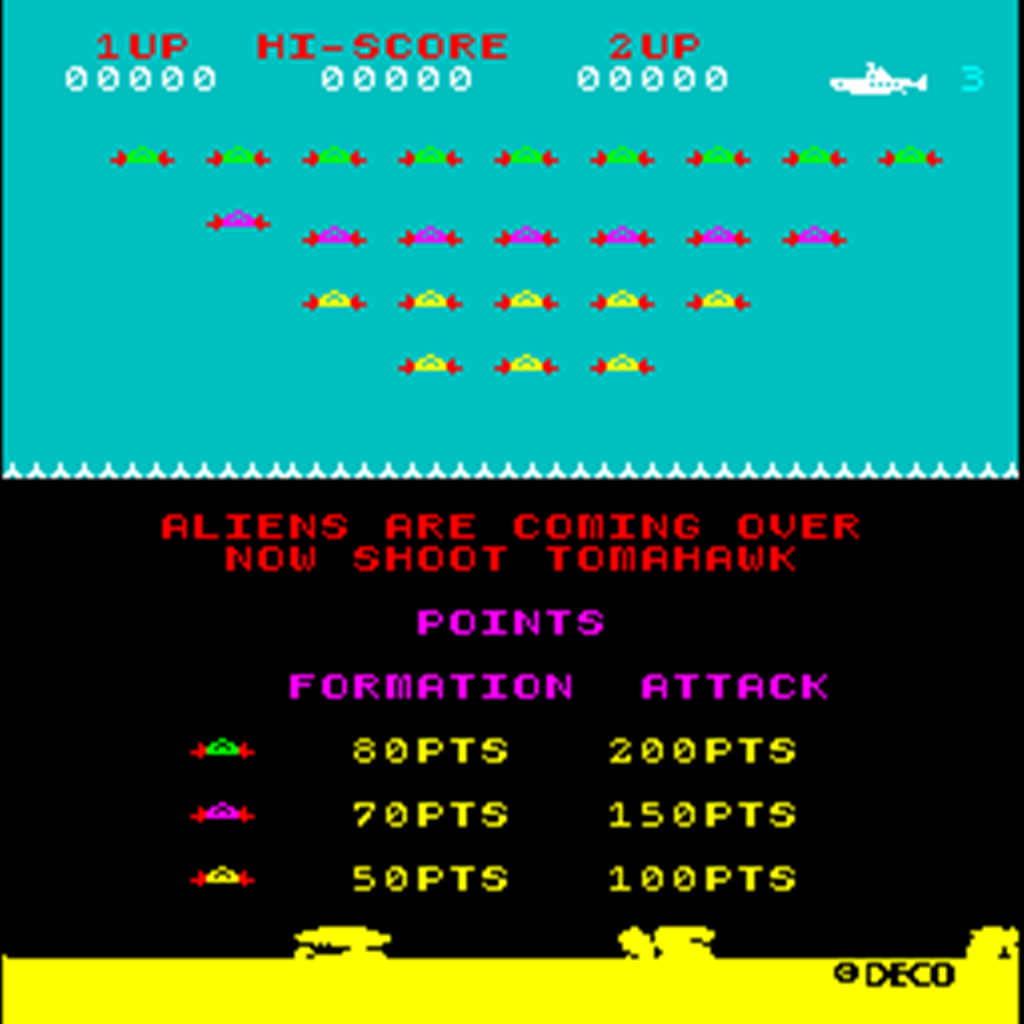
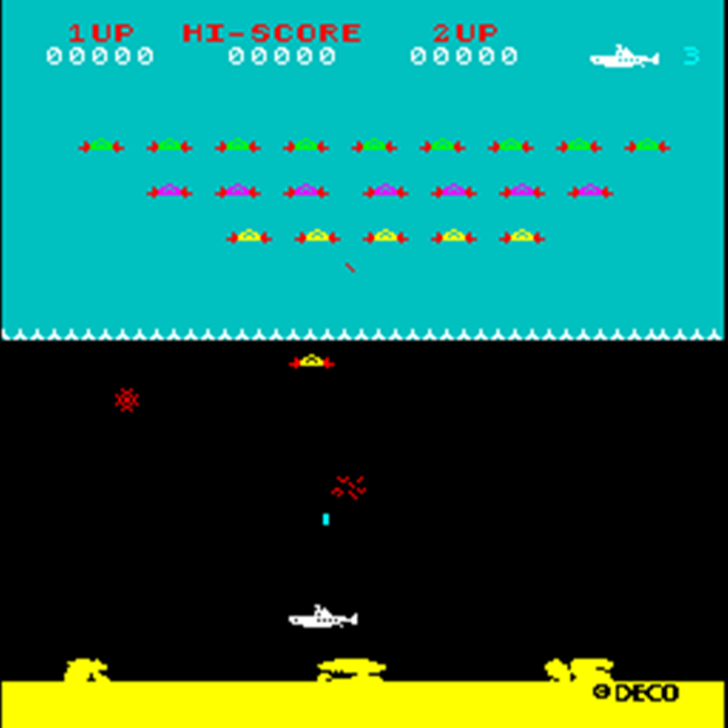
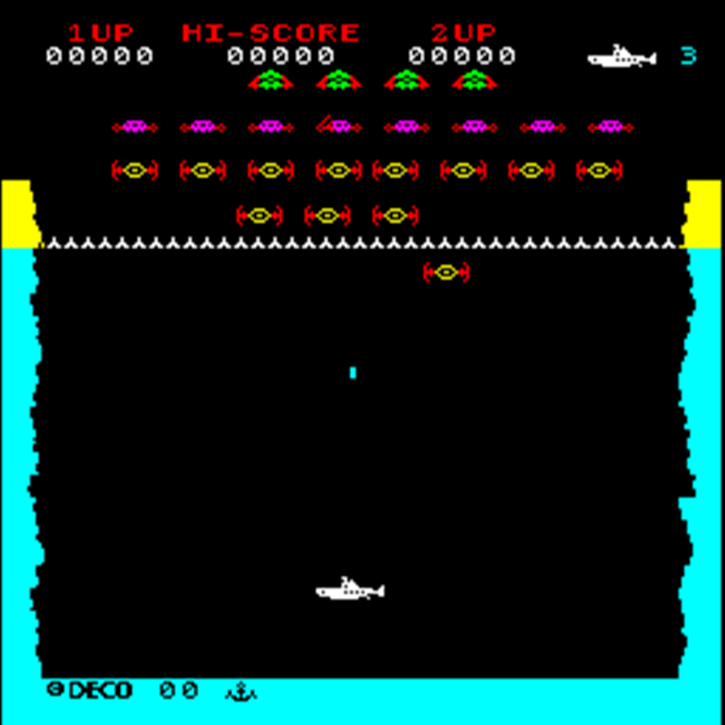
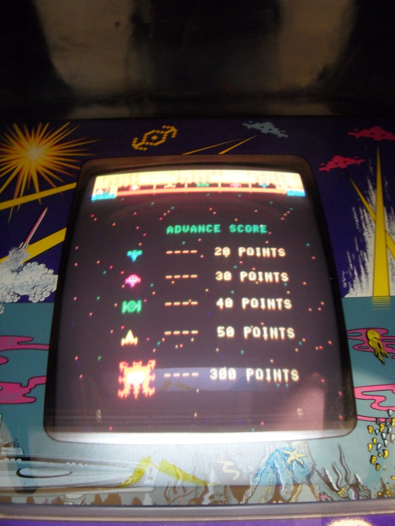
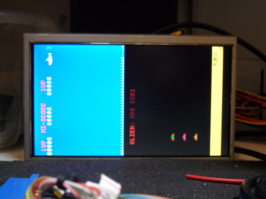
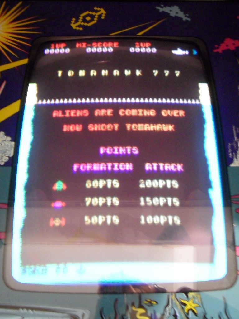
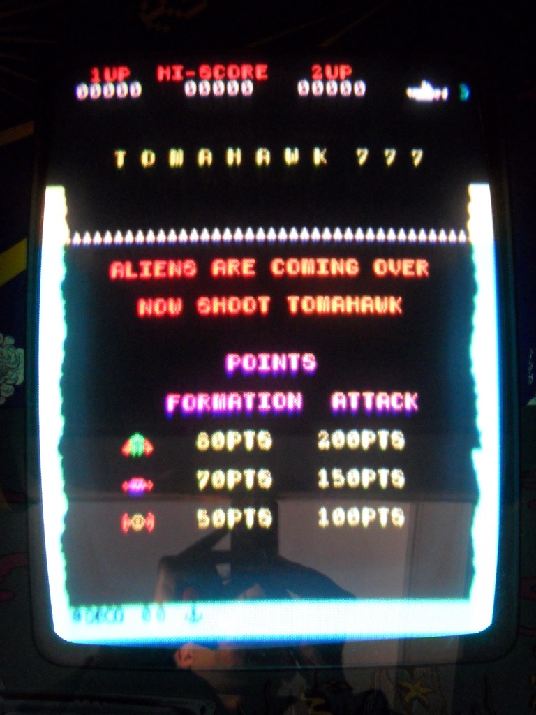
MAME has two ROM sets listed for Tomahawk 777, an older Rev 1 and a newer Rev 5. Based on the artwork on the Sea Scare cabinet it looks like it has the aliens in the Rev 5 set. Also, zooming up the scan of the flyer shows the "U" walls along the sides & bottom present on the Rev 5 set so I'll program the Rev 5 set.
| AF PCB Location | AF EPROM Label | AF MAME ID | Base Address | T777 MAME ID |
|---|---|---|---|---|
| A4 | 572 | kei2 | 0xD000 | - n/u - |
| C4 | 573 | keii | 0xD400 | - n/u - |
| D4 | 574 | ke8 | 0xE000 | thawk.l7 |
| F4 | 575 | ke7 | 0xE400 | thawk.l6 |
| H4 | 576 | ke4 | 0xF000 | thawk.l3 |
| K4 | 577 | ke3 | 0xF400 | thawk.l2 |
| A5 | 578 | kei0 | 0xD800 | - n/u - |
| C5 | 579 | af579.08 | 0xDC00 | thawk.l8 |
| D5 | 580 | ke6 | 0xE800 | thawk.l5 |
| F5 | 581 | ke5 | 0xEC00 | thawk.l4 |
| H5 | 582 | ke2 | 0xF800 | thawk.l1 |
| K5 | 583 | af583.00 | 0xFC00 | thawk.l0 |
I derived the equivalent EPROM image mappings between Astro Fighter and Tomahawk with a view to trying a simple ROM swap.
|
I blanked and programmed the Astro Fighter 2708's with the equivalent Tomahawk images in line with the table above. Since the sound board is different I removed it and fitted sockets to allow an easy swap for a real T777 sound board in future (Astro Fighter runs fine without the sound board fitted).
|
Tomahawk 777 didn't boot :( On a closer look at the MAME driver it looks like there is a simple protection circuit to prevent a simple ROM swap on Astro Fighter. I don't have the schematics for T777 and I've not found them online but I suspect it's an extra circuit that's part of the T777 sound board. This experiment is sidelined for now :|

|
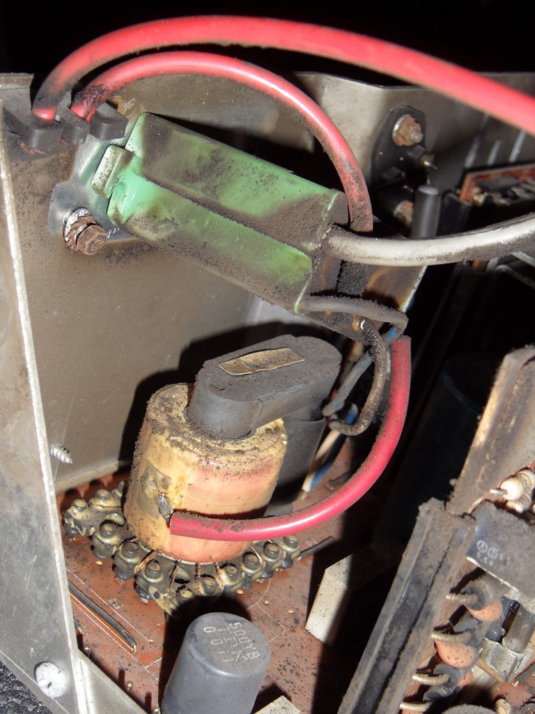
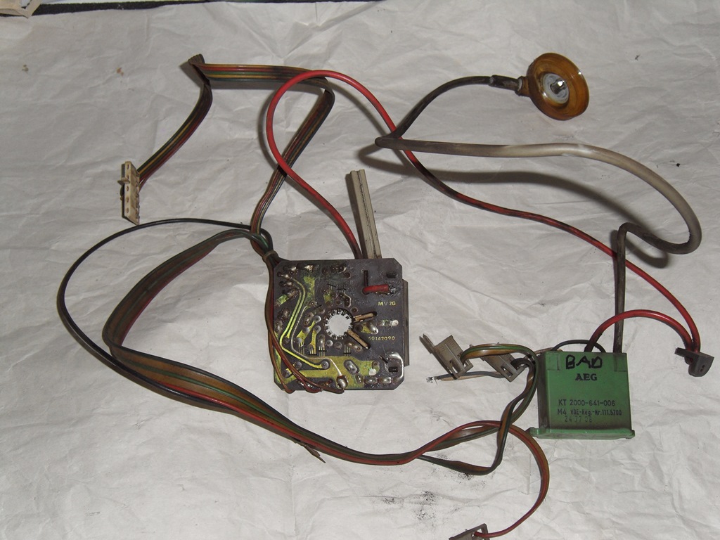
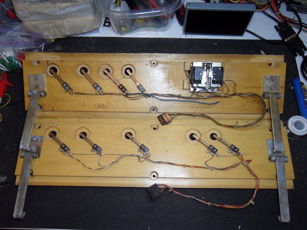
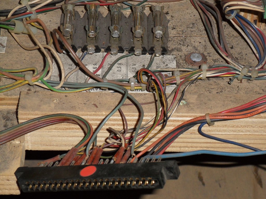
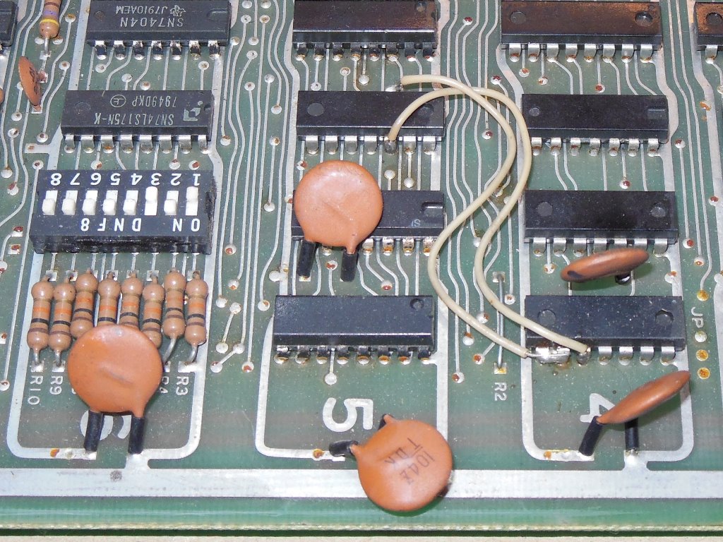
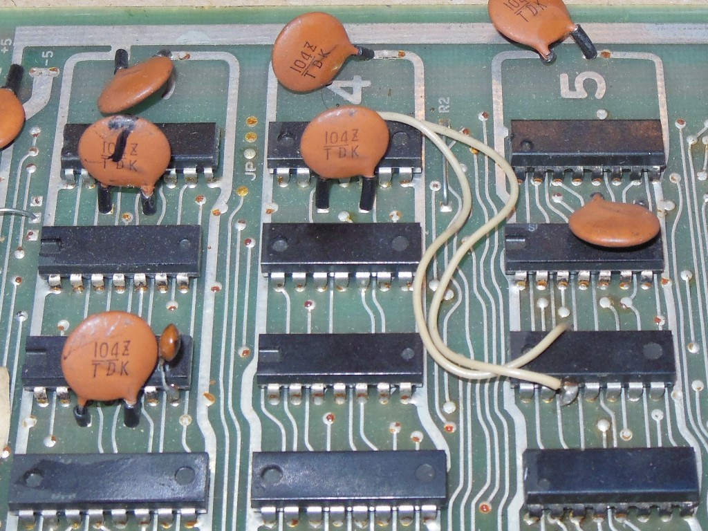
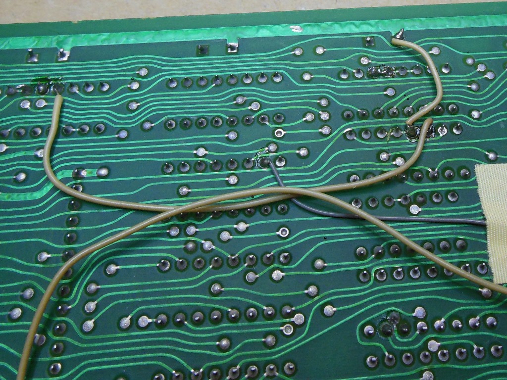
The Phoenix was plumbed into the Sea Scare cabinet using an adaptor for the original Data East wiring with two additional modifications. The first added what used to be the cage power lines to spare contacts on the Data East connector. The second cut the speaker lines in the wiring loom and added them to other spare contacts on the Data East connector. In addition to this, some extra power wires were added directly from the power regulator board to the Phoenix edge connector, presumably because the extra wiring dropped too much voltage and thus needed reinforcement.
|
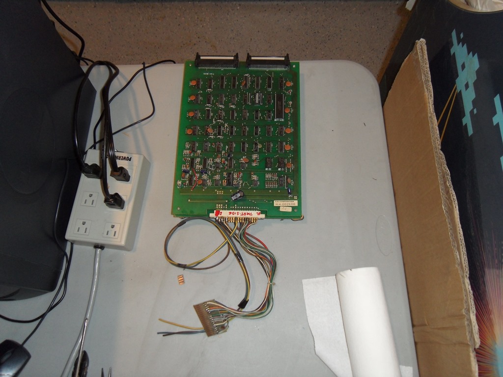
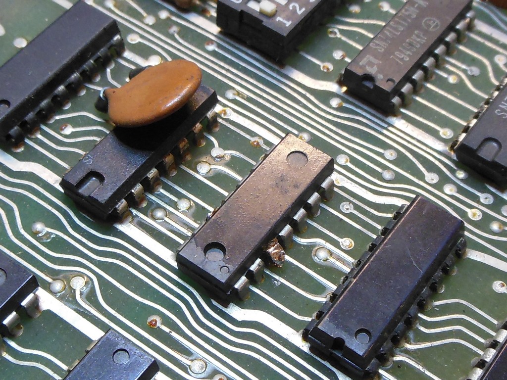
Removal was straight forward - unplug the adaptor and unsolder the extra power wiring. The Phoenix board will be a spare for my real Phoenix :)
|
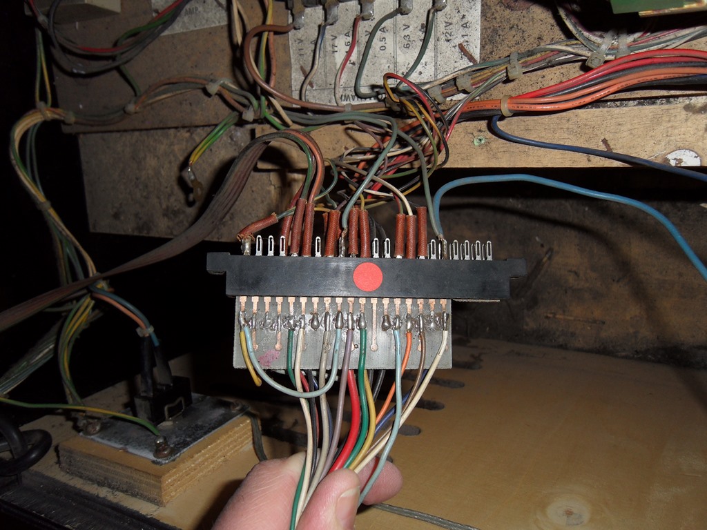
The "new" wiring on the Data East connector was easy to see - no eyelet covers versus the original wiring. The splice needed for the speaker line also easy to figure out.
|
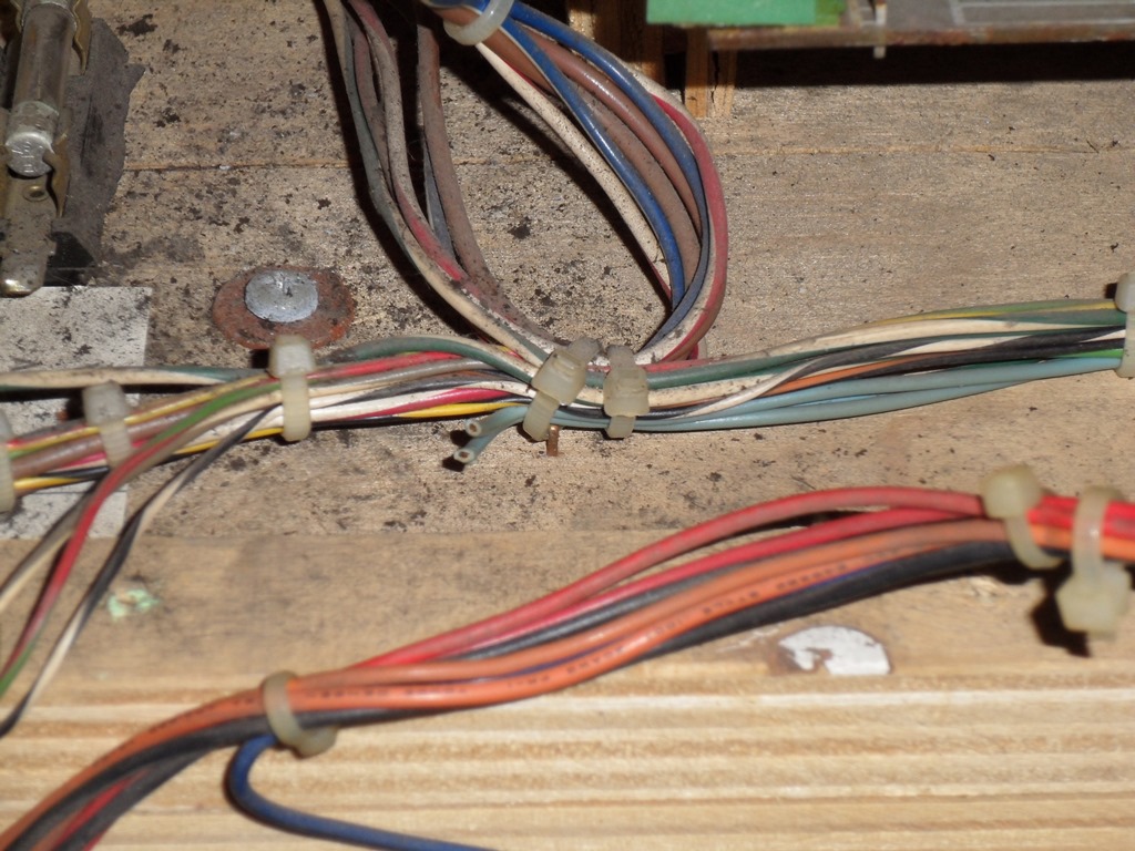
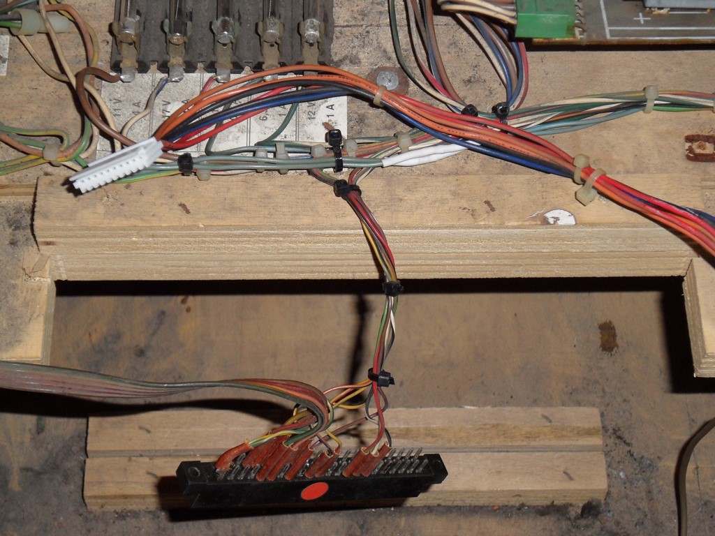
Fitted the 10-way Data East cage power connector (cross checking with the JAMMA adaptor and manual) and repaired the splice in the speaking wiring. Also added some additional cable ties to tidy it up.
|
Connected up the Astro Fighter. I already knew that the control panel configuration would be wrong from the manuals - player one/player two and right/left are swapped on T777). Coin worked OK but neither player start (now on right/left) worked. On further investigation I discovered I'd made a mistake fitting the Astro Wars leaf switches and used the wrong leaf tab. Fixing that and Astro Fighter started. The remaining buttons worked - fire on player one's game and right/left reversed on player two's game so all the remaining controls work OK. A real Data East Tomahawk 777 board set is on its way from Germany :)
|
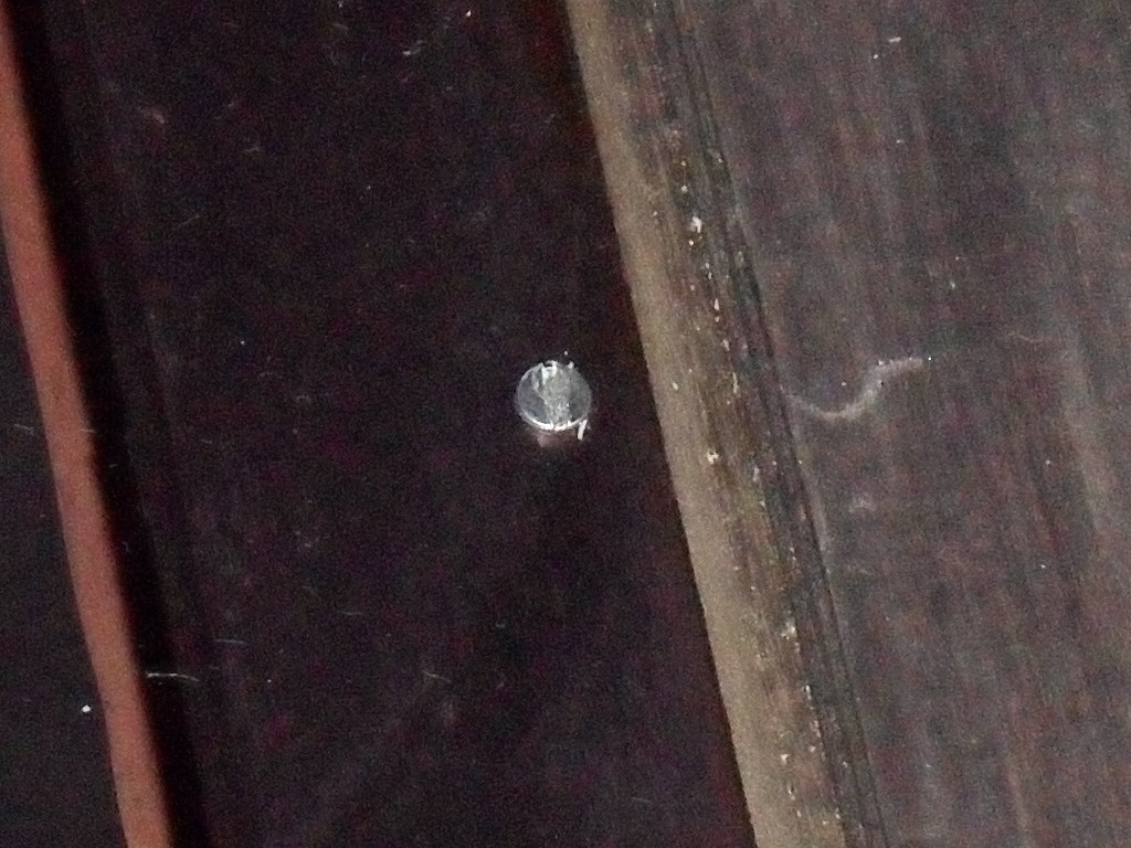
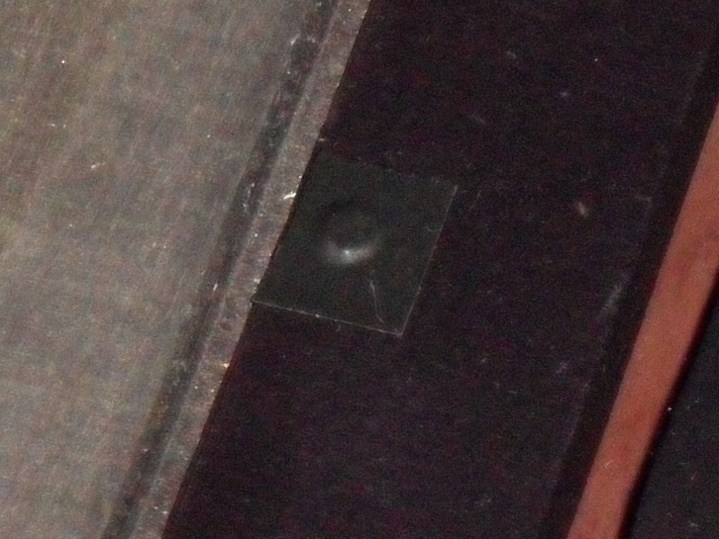
The monitor picture with Astro Fighter was OK but it's clear the automatic power on degauss is not working. There's 220V at the fuse and the fuse meters out OK so I'm suspecting a bad PTC.
|
With the degauss coil disconnected the output measured ~90V. With power off the three PTC pins all measured high resistance suggesting the PTC wasn't working. I replaced the PTC with the one from the scrap chassis (that measured low resistance on all three of it's pins) to fix the degauss.

|
Since I'm still waiting for the T777 boards to arrive I decided to fit the new base. First I removed the transit chain and castors, and then marked the outline of the blocks and side rails. I marked, pre-drilled and pre-screwed the foot blocks leaving the screw points just above the block surface to use as markers on the base. The back left foot needed a small void drilling out to go over the transit chain screw. After positioning the blocks a light tap with the hammer left the screw point marks as the markers for drilling the base screw holes.
|
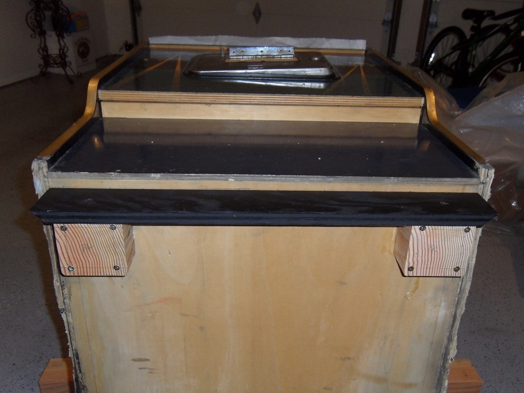
Using maximum strength wood glue in addition to the screws I fitted the two front foot blocks and the front rail. From that I marked the side rails and the location of the two back foot blocks and then fitted those. With all the foot blocks screwed/glued the castors went back on and machine uprighted allowing the back rail to be fitted. The finished product looks OK to me, though the original rails were stapled from the back & glued rather than front screwed and glued. The two black screws are not noticible in normal light (the camera flash has highlighted them in the photo).
|
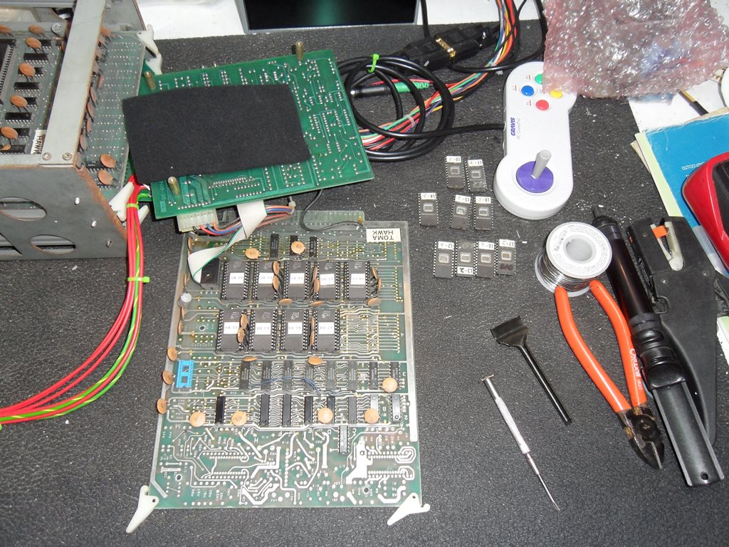
The Tomahawk 777 PCB arrives complete, safe and sound, thanks to SuperUlly on the Dragons Lair Fans forum. This one came out of a Data East Tomahawk 777 cabinet saved from the derilict Duke of Lancaster fun ship.
|
Tomahawk has a small separate sound amplifier PCB and that came with the set. Had the full Data East cabinet not been the source of the main board set this separate board would likely have been hard to find.
|
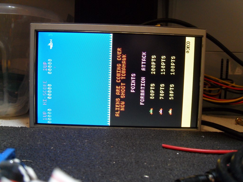
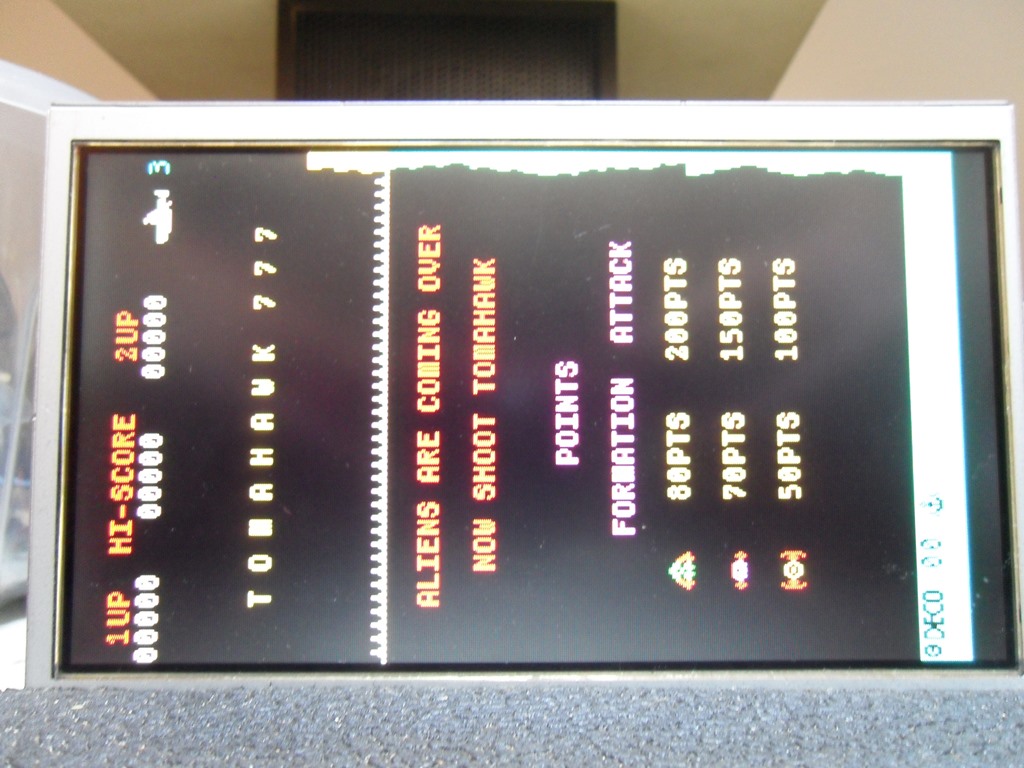
On power on the PCB set draws the score screen and then resets continously :( Graphics look OK suggesting the main bitmap graphics RAM is OK so I'm thinking bad ROM or work RAM.

|
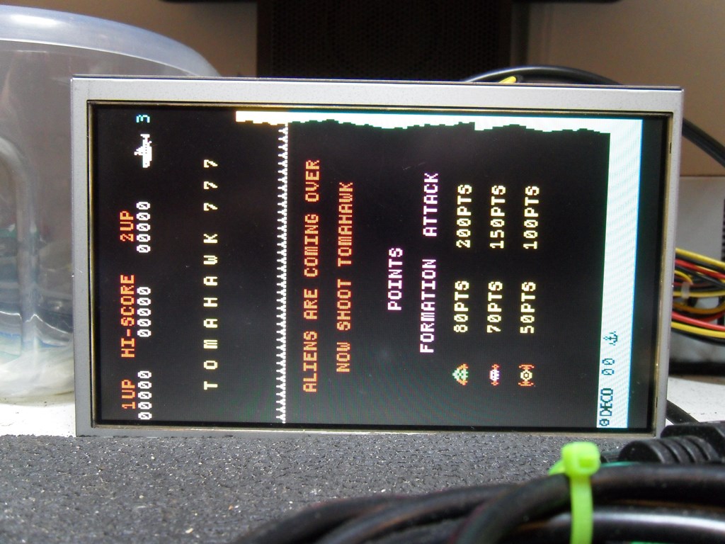
Since MAME lists only two known sets for this game I decided to dump the the ROMS for comparison. One ROM flagged as bad in the UniSite that no amount of pin cleaning and reseating would fix. Ignoring the UnitSites bad device check yielded bad data for it :( The remaining good ROMS all matched the rev 1 set in MAME. Replacing all the ROMS with the rev 5 set burned previously brought the board back to life working OK. Looks like the bad ROM was the fault.
|
Installing the boards into the cabinet yielded a prety poor picture with wrong colours and missing graphics :( Disconnecting the red gun made no difference so at least red was missing from the picture.
|
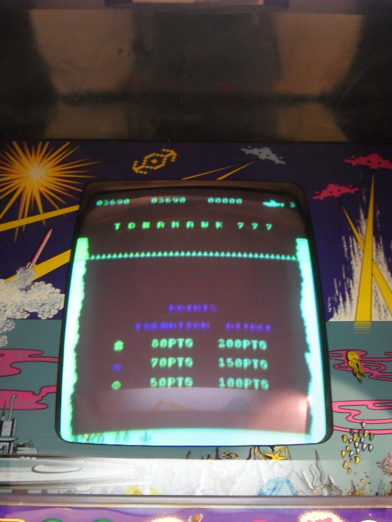
Reseating the edge connector and boards in the cage brought back the red and the associated missing graphic elements. Some pot tweaking (and there are a lot of pots on this monitor) yielded a usable picture and the game played OK in the cabinet :) No sound yet but on to that next...
|
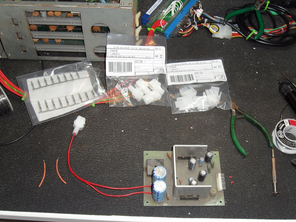
In the Data East cabinet the sound amplifier PCB takes its AC power from a
tap on separate transformer. In this Zaccaria cabinet there is a two-pin AMP
mate'n'lock connector that connects the amplifier AC power to a tap on one
of the Zaccaria transformers. I ordered a bunch of male and female conenctors
along with male and female pins to make up a suitable connector for the amp
PCB to connect it into the cab. Luckily the speaker/input cable was left in the
Sea Scare cab already. As expected the sound amplifier connected up perfectly.
Whilst the sound works it doesn't sound right to me. There are some morse code
like beeps when a game is started, the ship fire is like a higher pitched Galaxian
ship fire sound and the alien explosion is another high pitched sound that doesn't
sound right. The ship explosion sound seems to be OK. With neither schematics for the
sound board or any idea of what it should sound like I'll leave this as is for now.

|
Bought some credit button brackets done by a guy on the Dragons Lair Fans forum. I also needed to get some NC/NO double throw push button switches to go with them since the usual NO 2-pin buttons I had didn't work with the Zaccaria credit board. It looks pretty neat so I'll roll these out on all my cabinets ready for the show in June.
A short video of the Data East Tomahawk 777 (Revision 5) game in action on this cabinet. It's likely there is a sound fault but with no schematics or any idea of what it's supposed to sound like it'll have to stay as is for now.
|
To be able to start and play test the game on the bench I added one of the NC/NO buttons to the adaptor in order to coin it up. It didn't work, however. To be investigated later as needed.


|
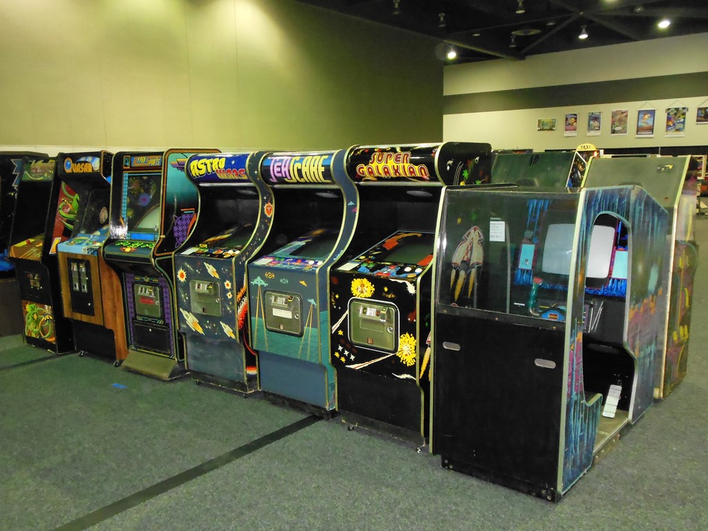
Returned to be with it's brethren.
Submitted for the first time into the show as one of ten machines. The Tomahawk 777 board died during final test and the game was replaced with another as there was no time to fix it the day before loading :(
|
Back on the bench there was no sign of booting, the same as when in the cabinet. Since it shares a broadly interchangeable CPU and IO board with Astro Fighter a little bit of board swapping confirmed that T777 booted up with an AF CPU board but still with issues. The T777 CPU board also booted up fine with a new 6502 processor and the T777 6502 processor was confirmed dead in the AF CPU board.
|
The game still had issues with misplaced graphics, crashes and resets. I noted while watching it that the issues didn't look like they were bitmap RAM problems. Swapping with an AF ROM PCB ran AF without issue confirming that the problem was with the T777 ROM PCB.
Whilst swapping boards with AF I noticed a couple of interesting differences.
- The Tomahawk CPU board has the forth ITT 4027 colour RAM fitted whereas Astro Fighter
has an empty position with a strap in that position.
- Various other wire mods on the Astro Fighter CPU & IO are not present on the Tomahawk
flavour.
|
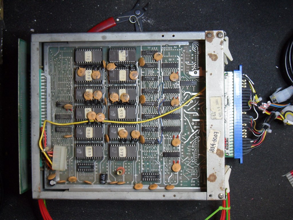
Taking an educated guess that there was a RAM issue I setup the board pack on the bench using an open edge connector reclaimed from an Astro Fighter. Since the boards can be arranged in any order the board to work on can always be plugged into the top slot for ease of access and there is *just* enough space for the ROM and sound combo to fit in the middle slot, splaying slightly the top and bottom boards. In this case the ROM is the one to investigate anyway. The scope showed nothing obviously unusual on the 2114 RAM address, data & control. Trying a piggyback device on the RAM made a substantial improvement to the degree the game was almost running fine. Changing out the 2 x 2114 program RAM fixed the issues :)
I also managed to fugure out why the game wasn't coining with the NC/NO switch - the service NC/NO needs to be tied in a specific way for the coin input to work. With both service inputs tied to ground and one side of the coin input tied to ground allowed a single NO button to coin the game (albeit without any debounce).
|
I'd known that the sound wasn't right but had left it until I could get a manual with schematics to sort it out. A little bit of further browsing the web turned up a scan of "Electro Sport Tomahawk" schematics. As far as I can tell it's identical to Tomahawk 777 (likely a bootleg as Data East isn't mentioned anywhere). With schematics in hand I investigated the sound board. Fairly straight forward - there are 7 sounds and 1 mute control. The sound I was missing entirely was SONAR due to a bad uPD4013. A couple of NE555's cleaned up a couple of the others. Since I don't have a second board to compare against I don't know if they are all 100% correct but they are all outputting something and there are sounds for all the game play elements (note in the picture above the missing uPD4013 is strapped as I'm waiting on a replacement part to arrive. The strap bypasses the D-type thus making the sonar sound run twice as fast as it should).

|
ChrisChris from the Dragons Lair Fans forum did an amazing job of reproducing the marque artwork by hand from the flyer he found. Mikonos from the Zona Arcade forum printed the marque for me. The print is a little bit light so I used a paper backing to filter the light slightly to reduce the brightness a little.
Fitted the marque back into the cab and it looks pretty good :)
Submitted for the second time into the show the monitor died during pre-show burn in :(
The Hantarex MTC-90 lost main HV and was arcing in the focus circuit. I suspected a tripler failure but had no spares :(

The first step was to attempt to identify the triplers compatible with this monitor. As far as I knew triplers were generally very simple with the main variations being physical size, mounting holes and whether they have the focus pot built into them. P-Man in the UK had already given me a couple of NOS triplers that were not the same as the MTC-90 ones so before attempting to adapt them for the MTC-90 I searched for the original part hoping that it might be still available.
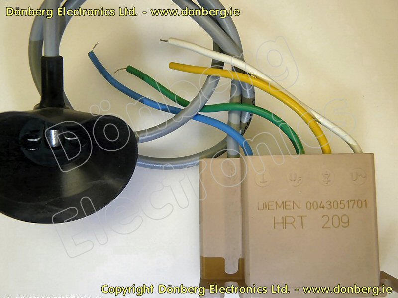
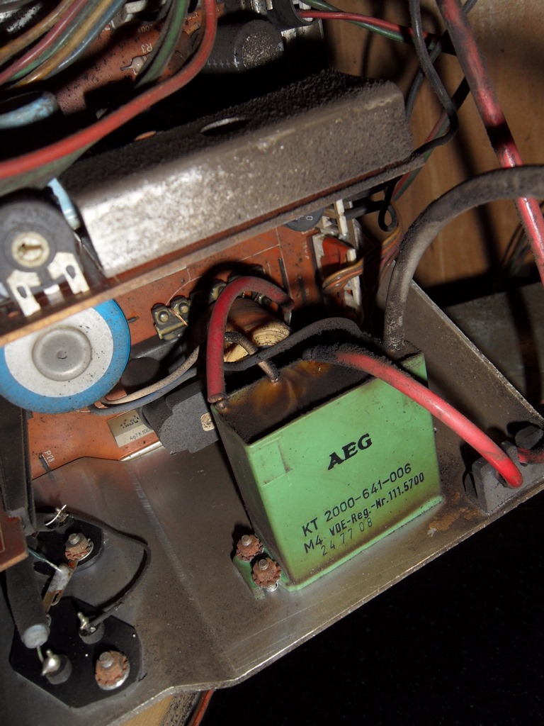
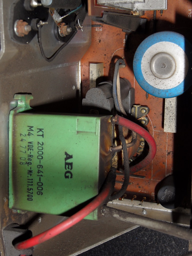
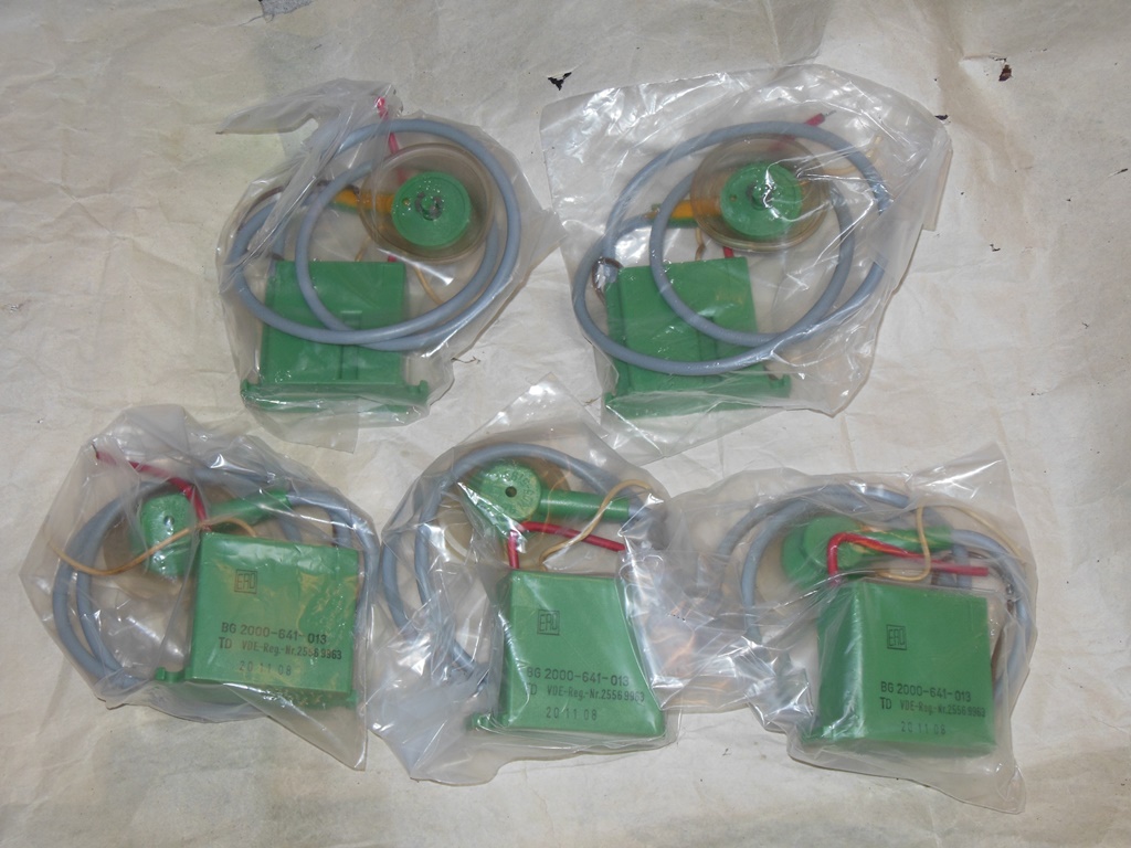
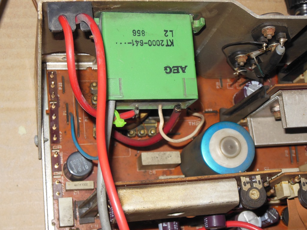
The original part is an AEG KT2000-641-.../AEG KT2000-641-006 that I suspected was the same as the BG2000-641-xxx series. Bing found a hit on this for the HRT 209 that looked the same with the same colour wires and mountings. Donberg listed the following equivalents for the HRT 209:-

|
A little good luck turned up a NOS batch of 5 equivalent triplers on Ebay Greece for very little money and I BIN'd all of them. They looked physically correct with the same wiring - all good signs. However, replacing the tripler yielded no change - the neck board was still arcing :(
|
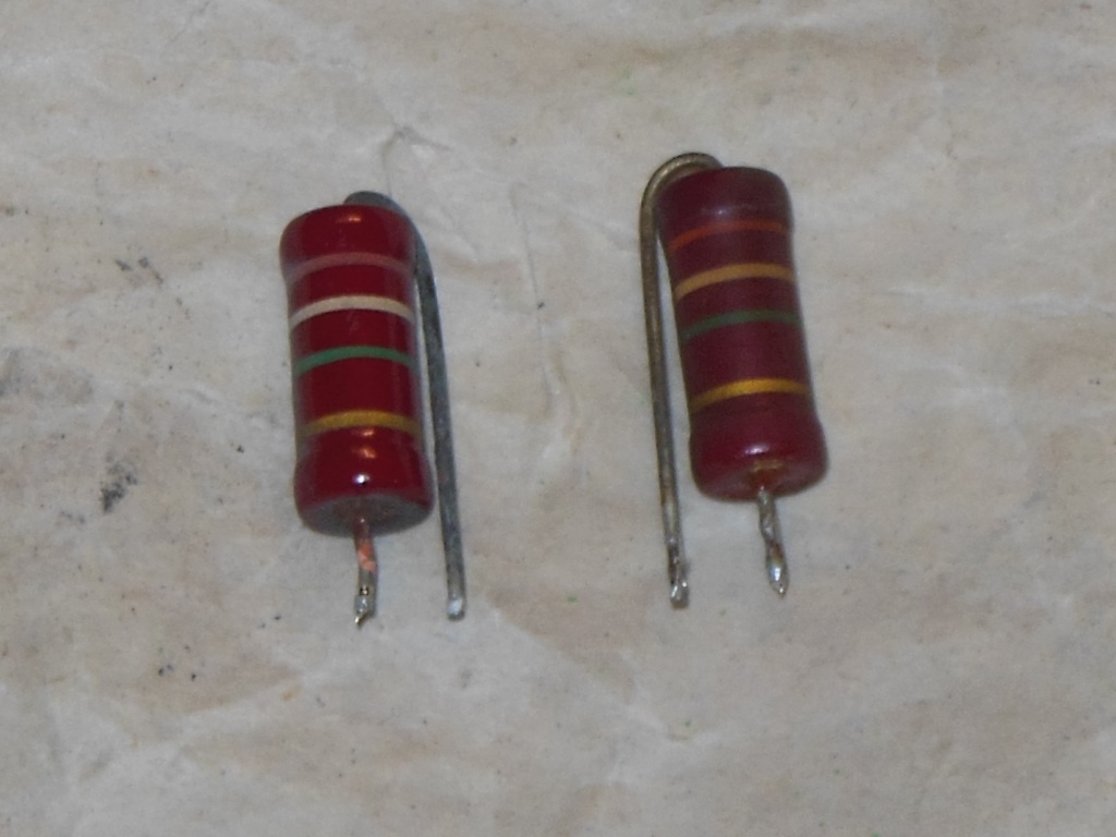
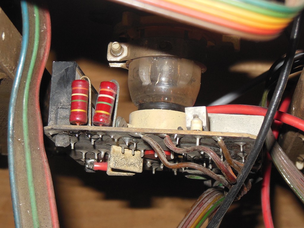
Attention turned back to the schematics to determine what was arcing to where. The pair of resistors are for the focus divider chain and thinking about it there should have been no electrical reason to arc between them because they are connected in line with each other. A check with the multi-meter revealed that one of the resistors was open. Replacing it with one recovered from a scrap chassis fixed the arcing :) Still no picture with no signs of life from the game board, however.
So what was going on? The open resistor should not have caused arcing if the focus is tapped off according to the HR diagram above. I suspect what's actually happening is that the focus voltage is generated from a bleeder resistor tapped from the HV output inside the tripler. This means that if the focus is open (sinking no current to drop the HV across the bleeder) the focus output becomes equal to the HV output. Worth knowing for future reference when I have focus arcing problems in future.
|
The repro marque was not as opaque to the marque light and was thus overly bright. I'd tried a sheet of paper behind it previously but that caused the paper texture to show through and it was still a bit too bright. The next idea to try was spray painting the fluorescent tube to reduce the light output. The first coat yielded something that was heading in the right direction and the second coat looked perfect - a nice even light.
Note that the below pictures are full resolution to show detail.

|


|
I only have a couple of Tomahawk 777 CPU boards but a pile of Astro Fighter CPU
boards so I decided to look into the conversion of an Astro Fighter CPU into a Tomahawk
777 CPU. Key differences:-
|
The parts side straps shown above when removed also need repairs.
|
The repairs are as follows:-

|
I fitted the extra RAM, removed all the solder side straps and restored all the associated cut tracks with small straps. The conversion is quite neat when completed and appears to work fine.

|
As noted previously, once the monitor was fixed the next problem was that the board appeared to be dead. Removing the whole cage and testing on the bench showed the same thing - dead. Setting up with the CPU board on the top and a quick check with a working Astro Fighter board revealed that it was a CPU board problem. The starting point was the blank screen since usually no boot would leave garbage on screen. Poking around with a scope indicated 5K pin 5 (video) and 5K pin 9 (blanking) were active. Looking at the colour RAM showed the output idle and their chip select line floating. Tracking that back to the 7442 at 3F showed that it had resonable inputs but all it's outputs low or floating. Replacing the 7442 (in this case, with Russian Tesla MH5442 mil. spec.) fixed the game.

|
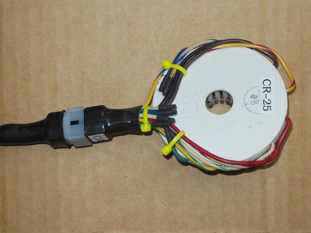
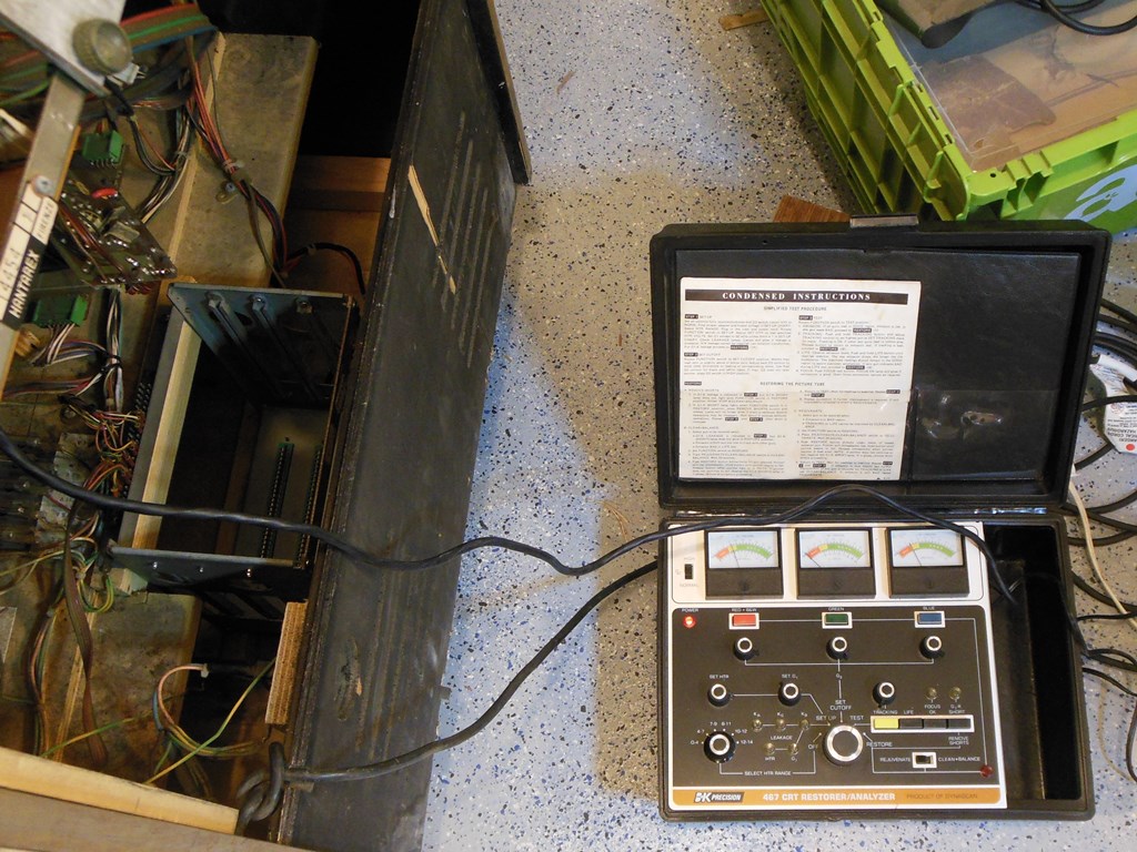
The picture on the Hantarex MTC-90 in this game has always been poor. I tried swapping both the video input board and colour drive board with no difference to the picture quality. A local expert (DOk) confirmed that my BK467 was working fine so I wanted to test out. A little bit of research indicated that the CR-1 that came with the unit had the same neck socket as the ITT A51-211X in this cab. The BK listed this tube as on the CR-25 adaptor. Comparing the CR-25 with the CR-1 showed the difference to be only that the CR-1 has 4 pins connected that are not connected on the CR-25. Therefore, to convert a CR-1 to a CR-25 needed only 4 wires to be cut.
|
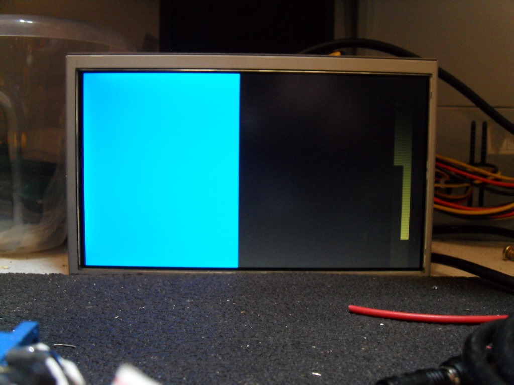
Initial testing with the BK467 showed near zero output on RGB :( Initial rejuvenation brought red and blue up to just above "bad" in the yellow zone but green remained near zero. A further rejuvenation brought red and blue almost identically into the "good" zone. No amount of rejuvenation would raise green out of the middle of the "bad" zone. The rejuve lamp barely flashed and the meter wouldn't jump into the "good" zone on the green gun . It looks like this is the best I'll get out of this CRT. Reconnected back to the chassis the picture was improved but still somewhat poor.

|
About an hour into the final burn in test the blue output failed :( A quick swap of the video input and RGB drive boards with a couple of known good workers still had no blue output.

|
Wheeling the cab over to be within scope range and poking around suggested no difference in output between the colours on the RGB drive outputs of the drive board. Attention thus turned to the neck board and CRT. Using a meter to test the connectivity from the RGB drive to the neck socket gave inconsistent readings. The neck board doesn't seem to fully match the schematics so I took some resistor values from a scrap neck board to compare with this one:
|
Replacing R1 with the one from the scrap neck board brought back blue and the cab was working again :)
|
Pre-show testing showed no issues and the game was submitted into the show. Of the three MTC-90 based games in the show this was the only one that went the distance and remained working throughout the show.