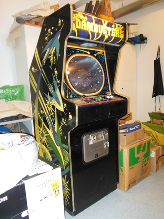
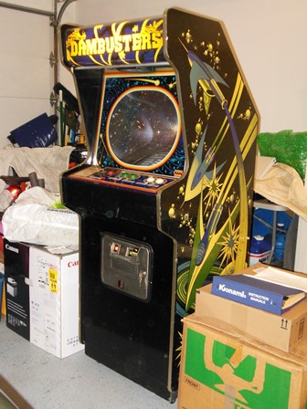

I had already acquired a NOS Hantarex MT RV 20" black & white vector monitor a few years ago to use to build a Space Fortress. I'd also acquired game PCB's, a marque and then recently had the good fortune to find a complete power plinth & wiring loom courtesy of Andys Arcade. What was missing was a cabinet, control panel, monitor glass and monitor surround.
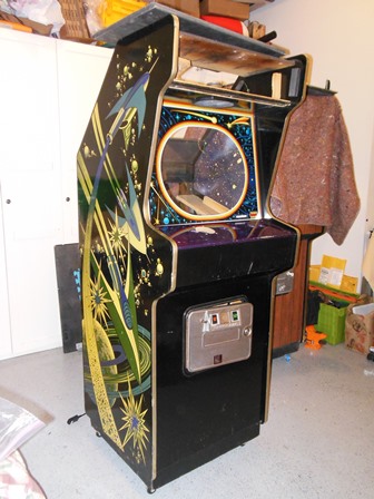
Whether this project could be considered a restoration or new build is unclear - the parts are all original but the actual base cabinet would be an early Quasar that utilized the same cabinet artwork as Space Fortress. I'd always planned to restore a laminated and converted Quasar to use for this project but discovered that the laminate conversion could not be successfully undone. The cabinet was also in rough shape overall. Instead, I had previously completed a Dambusters restoration that was based on a Quasar conversion in which the base cabinet was in excellent condition. Since the Dambusters was a conversion anyway and is not a space themed game fitting its cabinet, the plan was to "move" Dambusters into the woodgrain cabinet to become a British game in a typical British pub/chip shop woodgrain cabinet. The empty Quasar cabinet could then be used for the Space Fortress restoration.


|
The base Dambusters restoration was completed in 2019.
|
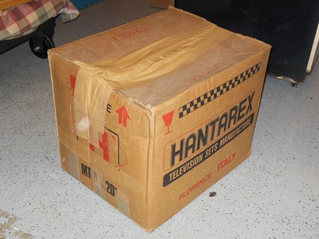
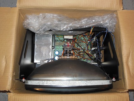
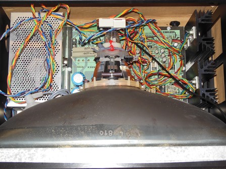
The Hantarex MT RV 20" black & white vector monitor inside the box was in clean, complete new condition.
|
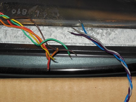
Two cables were provided with the monitor that ended in bare wires.
|
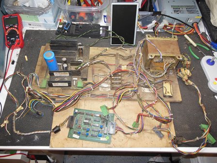
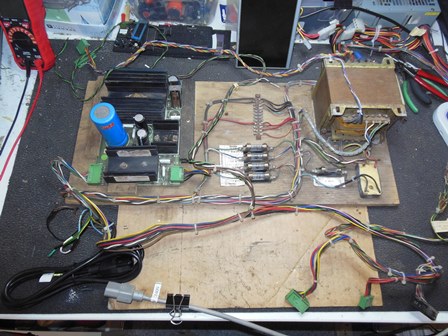
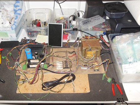
Overall the power plinth was complete but with moisture damage to the plywood base and rust on the metalwork. The wiring was surprisingly complete, including the coin door and control panel wiring with some remaining labels for the signals. Whoever removed it did a thorough job considering future re-use.
|
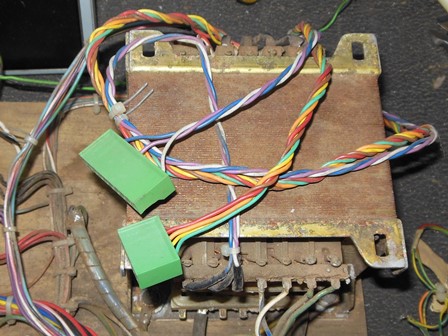
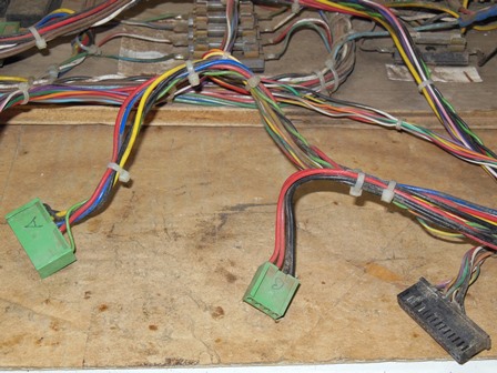
Both power connectors for the vector monitor were present on the wiring loom so there was no need to use the ones in the monitor box.
|
The game PCB connectors comprised three connectors for audio PCB, main PCB power & main PCB control (coin and controls). There should have been a fourth connector for the video cable from the game PCB to the monitor that was missing.
|
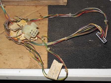
The control panel loom was present and partially labeled. Along with it was a 9-pin square block connector that wasn't accounted for in the Space Fortress manual. Closer inspection found this to be a non-Zaccaria modification to separate the control panel.
|
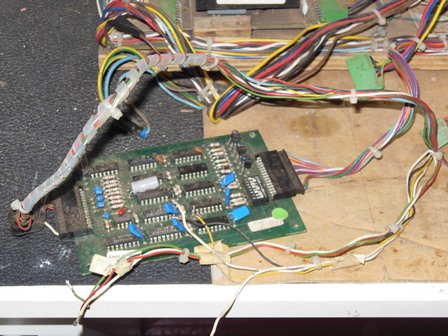
Both sides of the credit PCB wiring loom were present. Only the coin door light cable had been cut a little short and would need patching.
|
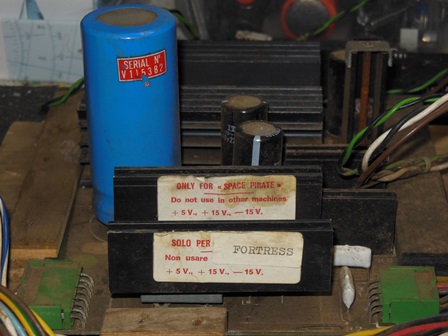
Space Fortress & Pirate use a modified version of the 1B1126 regulation PCB that substitutes +15V & -15V for the monitor in place of the +12V and -5V used on other games - hence the warning labels (that it would blow up other raster games).
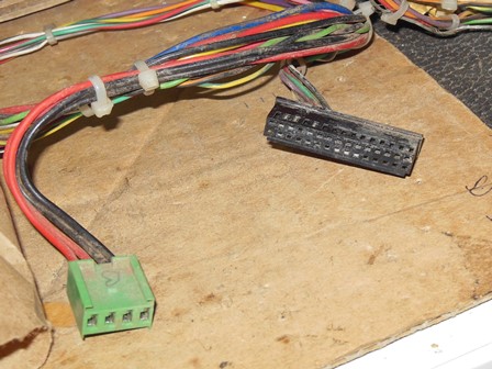
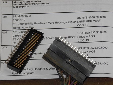
|
The Zaccaria Space Fortress game PCB used different connectors than the Cinematronics Star Castle version. One of those connectors was a 2 x 15 pin AMP plug for the control panel inputs. The matching PCB connector for that plug still exists, TE Connectivity 280387-2.
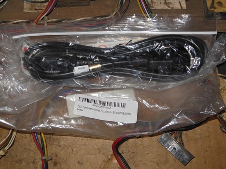
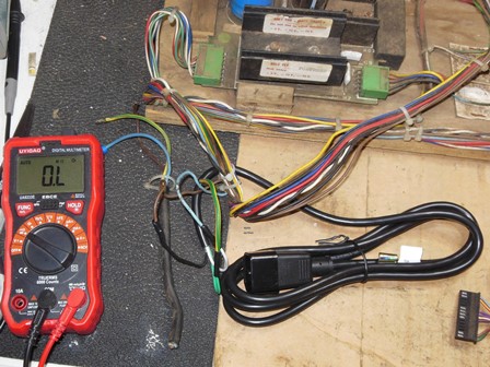
|
A 6ft standard computer power cable was trimmed and spliced in to replace the original cut power cable.
|
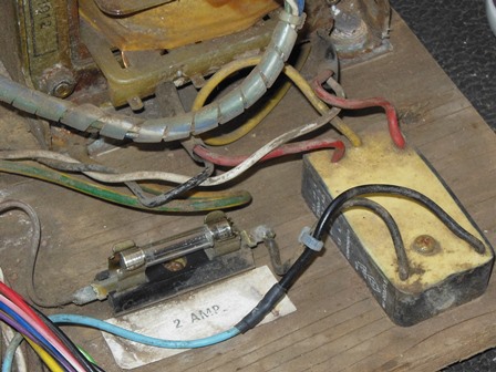
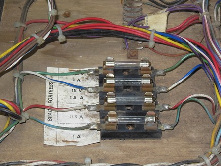
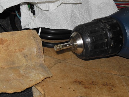
All the fuses showed signs of corrosion. The fuses were lightly sanded with fine paper and the fuse holders polished with a wire brush Dremel.
|
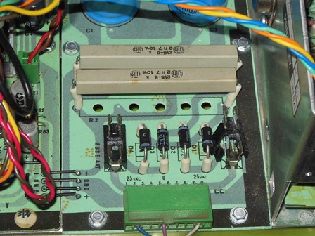
First power on revealed that all the power rails were working, +5V, +15V and -15V all looked good with no load. On the Hantarex MT RV power inputs the 28VAC and 35VAC were also present.
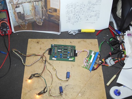
The initial plan was to build a Zaccaria Space Fortress to Asteroids adaptor to support
running Asteroids initially for testing and also allow an option to use the Cinevectron
reproduction game PCB in future. There were a couple of problems to solve with that:
| Pin | Colour | Voltage | Phase | Tap |
|---|---|---|---|---|
| 8 | ||||
| 7 | ||||
| 6 | br/wh | 18.0V | * | centre |
| 5 | br/wh | 18.0V | 36V | |
| 4 | gr | 10.5V | ||
| 3 | gr | 10.5V | * | |
| 2 | bl/wh | 18.0V | centre | |
| 1 | bl/wh | 18.0V | * | 36V |
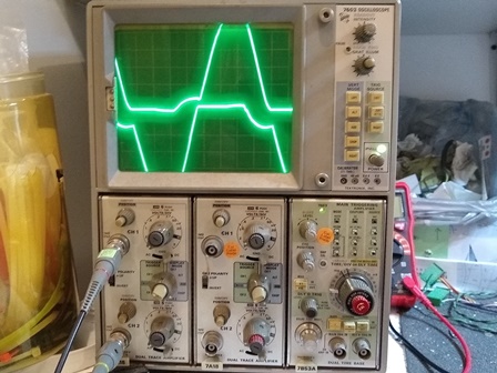
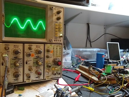
The centre tap configuration was verified on the scope as 40.5VAC sine wave no load.
|
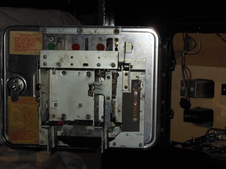
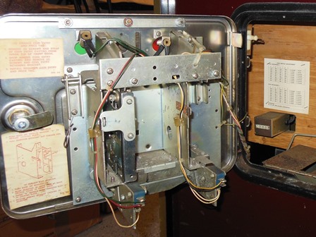
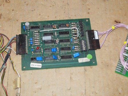
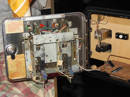
Since Quasar doesn't use a 1B1145 credit PCB the coin door harness had been moved over to the woodgrain cabinet. A 1B1145 based coin door harness was included with the Space Fortress cable set and a photo from a Zaccaria Scramble was used as a reference to complete it by adding the microswitches and splicing in the door lights.
|
The 1B1145 credit PCB wasn't working so the bypass hack was applied and the harness was installed onto the coin door.
|
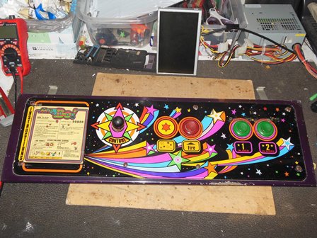
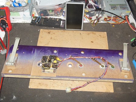
The Mr Do! converted Quasar control panel from the woodgrain cabinet would form the base for the Space Fortress control panel.
|
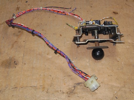
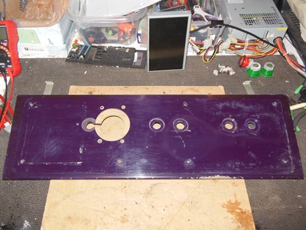
All buttons, joystick, and harness from the Mr. Do! conversion was removed along with the universal control panel overlay to leave a blank panel with a few leaf switches. A large cut out had been made to support the joystick that would need to be repaired.
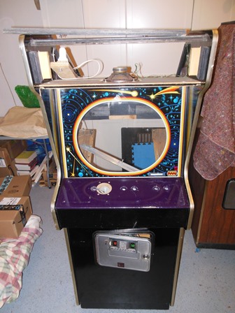
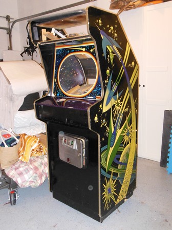
|
|
Restoration was paused for 2022 Northwest Pinball and Arcade Show preparation.
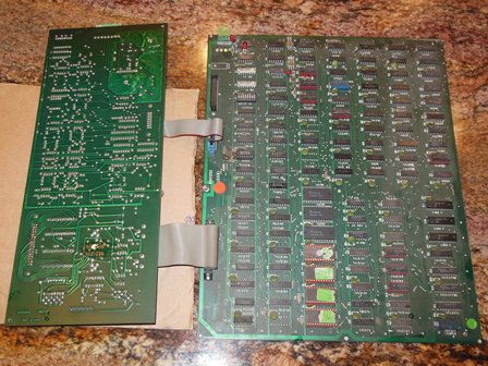
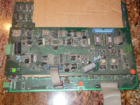
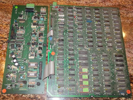
|
A visit to the UK brought back two sets and one CCPU Zaccaria Space Pirate game PCBs.
|
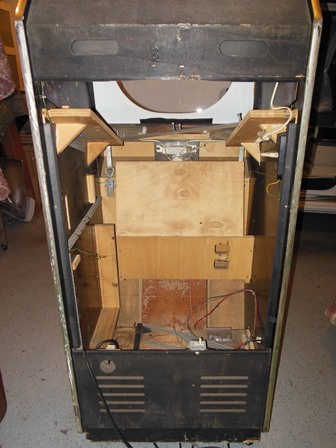
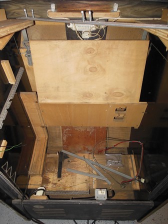
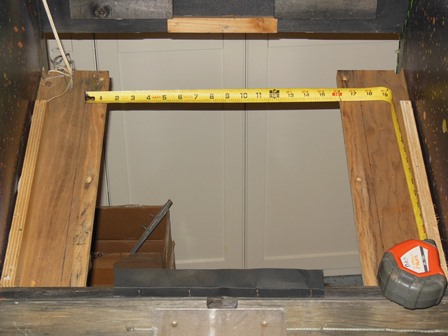
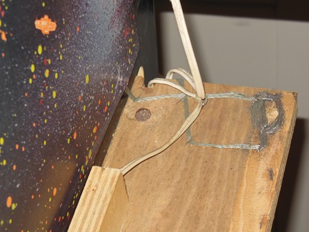
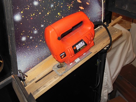
The Hantarex MT RV is mounted horizontally and measures 17.5" across. The original Quasar monitor was a 15" wide vertically mounted Philips KT-3 so the monitor shelves needed to be trimmed down by 1.25" on each side.

|
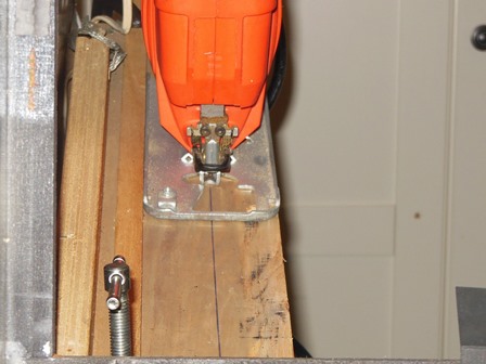
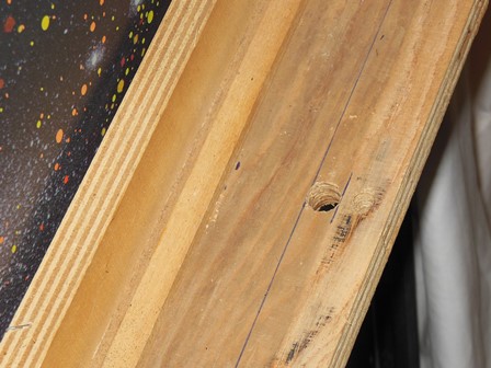
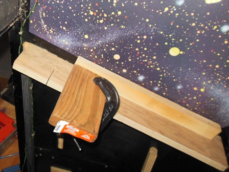
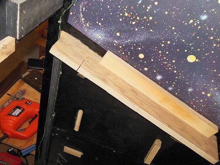
The position of the jig saw blade relative to the saw base plate was staged, marked on the shelf, and guides set in place with a couple of G-clamps. A pilot hole was drilled near the centre to allow two cuts - one towards the front and the other towards the back to allow the blade to reach all the way to both ends.
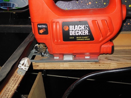
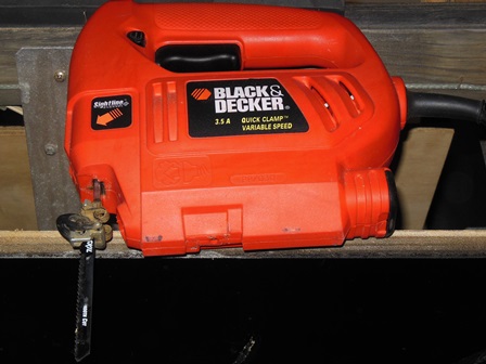
|
A slow & steady cut was used to trim the shelf. In order to trim the last half inch, the saw base plate was temporarily removed.
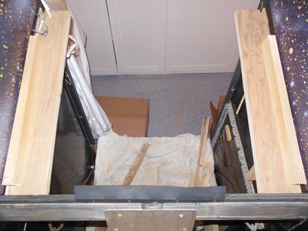
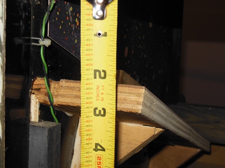
|
The finished shelves looked neat and measured correct. There was still one problem to be solved - the gap between the back of the cabinet and the shelf wasn't large enough to allow the monitor to slide in. A look at photos from an original Space Fortress cabinet confirmed that the shelves were mounted lower to allow for the Hantarex frame. A solution for that would come later.
|
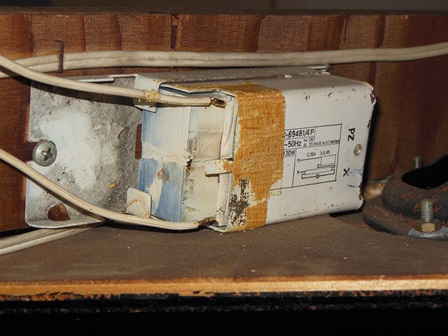
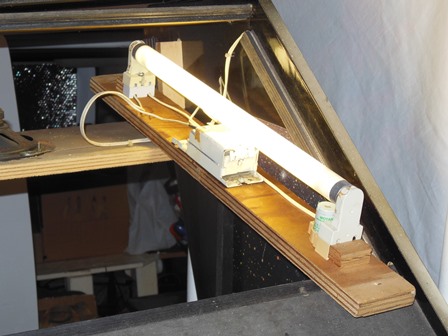
This was a previously working cabinet, so the marque light only needed cleaning, old tape removal & testing before fitting back into the cabinet.
|
|
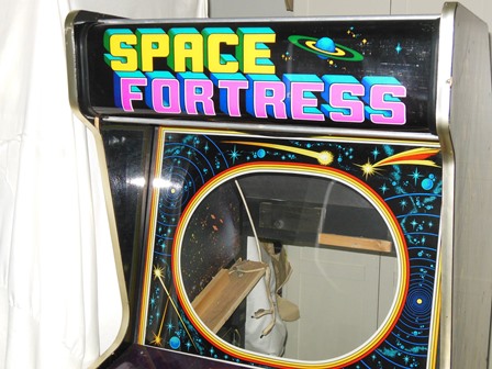
Scanned in the Space Fortress marque.
600 DPI Space Fortress marque scan (125MB).
|
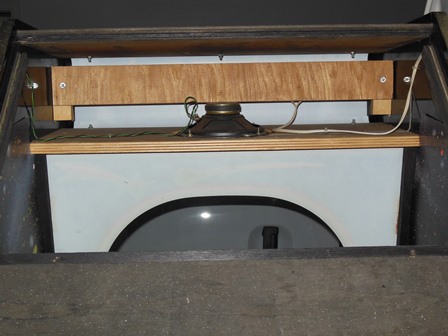
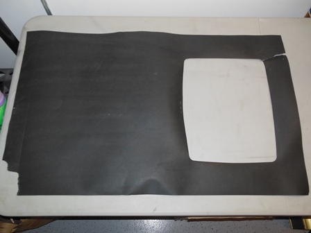
The Space Fortress marque was installed in the cabinet along with the marque light.
|
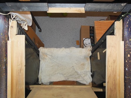
A native horizontal monitor surround was used to set the horizontal position of the monitor on the shelf at 3" (TBC) up from the bottom.
|
A closer look at the Space Pirate/Fortress cabinet photos on the web found that the native cabinet monitor shelf was also shorter than the raster vertical KT-3 shelves in this Quasar cabinet. Making them shorter would open the gap between the shelf and the back panel making more space to slide in the monitor.
|
|
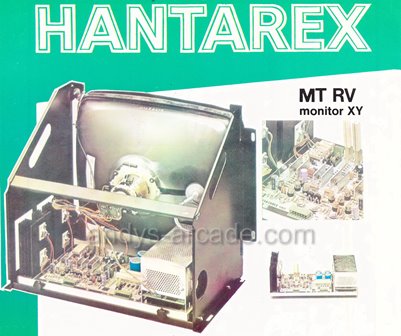
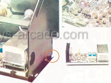
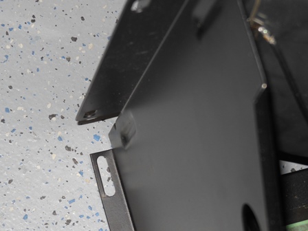
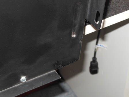
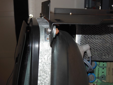
After the 2nd round of monitor shelf trimming another attempt was made to slide in the monitor and I discovered that it was going to be physically impossible for the monitor to fit in the cabinet - the front & bottom shelf lips left a gap too narrow for the thickness of the plywood shelf. The online photos for the cabinet didn't show this portion of the monitor, however, the Hantarex flyer did show a frame with one lip cut down. This would have been needed for it to fit the Zaccaria cabinet.
|
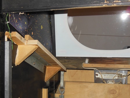
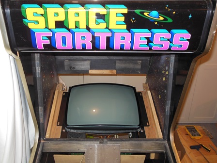
The frame lip was trimmed a little further than shown on the flyer to provide a little more maneuvering space and leave a clean edge. There was enough length on the CRT bolts and space between the CRT and the HV cage to allow the CRT to be mounted from the rear with a couple of washers to act as spacers. Taken together it reduced the CRT height by another half inch.
|
A combination of trimming the shelf depth, trimming the frame lips and mounting the CRT further back in the frame was finally enough to allow the monitor to slide in!
|
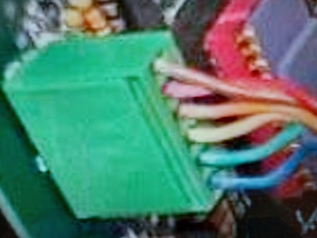
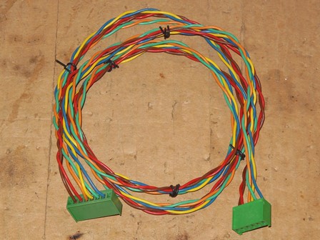
The power plinth and wiring harness was missing the vector signal cable connecting the audio DAC PCB to the monitor. In the box for the monitor was an unterminated NOS video input cable that was used to construct the missing cable using a reference photo found on the web.
|
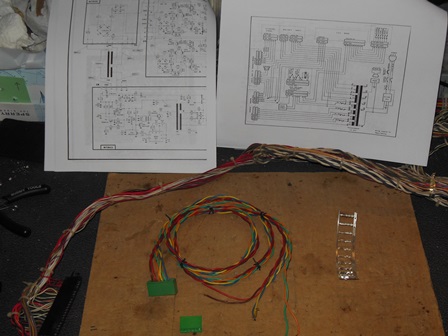
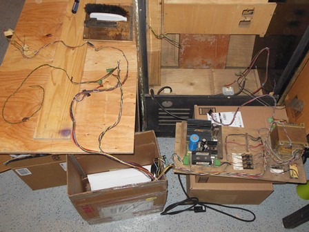
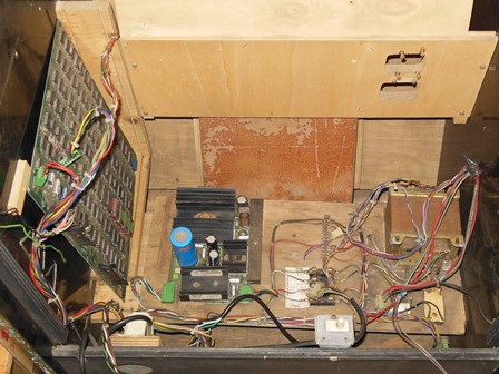
A spread out of the wiring harness confirmed that whoever removed it kept as much of it intact as possible. There were few hacks or missing sections. Staging in the cabinet identified some differences between the Space Fortress and Quasar.
Space Fortress used a top of cabinet back door interlock switch that was missing from the harness and bypassed. The mains switch was also missing & bypassed. Quasar used a bottom interlock switch and cabinet mounted mains cable & switch ending in a 3-pin connector to plug into the Quasar transformer assembly.
|
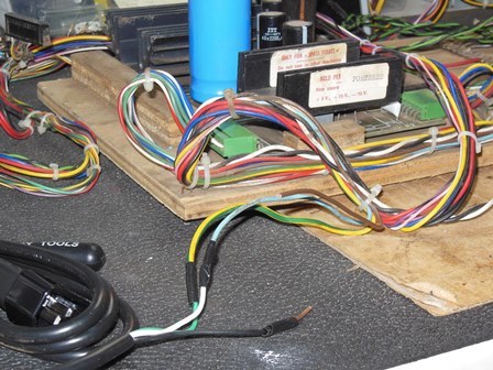
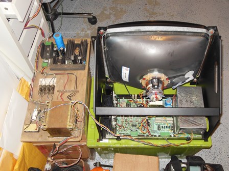
For testing the power plinth a temporary IE C14 power cable had been spliced into the cut mains input. This was removed along with the unused cables for the top interlock switch. The mains input lines were peeled out of the plinth wiring bundle to around the centre of the plynth and a connector fitted to mate with the Quasar mains input connector in the cabinet.
Connectors were also fitted for the in-cabinet speaker connection, coin counter and service outlet for the marque light. There were no hard lines in the cabinet such that the power plinth & wiring harness could be easily removed in future for game PCB or monitor repairs.
|
First power on with no vector signal input yielded an expected lit spot killer LED but
no HV or neck glow on the CRT. Checking power in found:
|
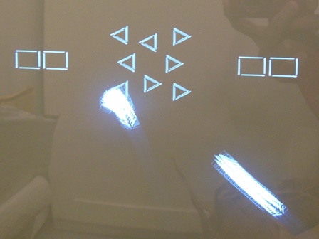
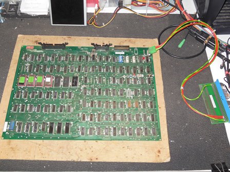
An initial pass through testing the Space Pirate and Space Fortress game PCBs using the Space Fortress audio-DAC PCB found:
|
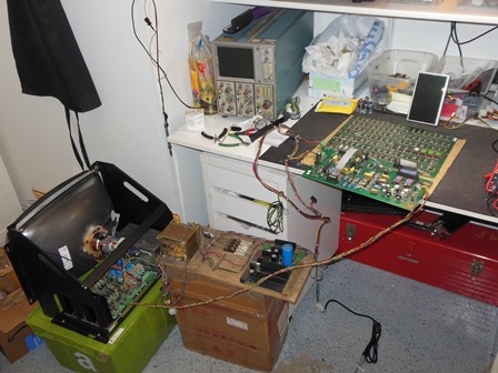
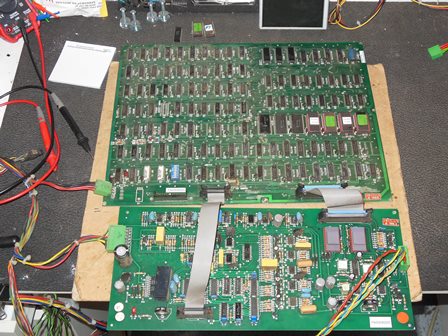
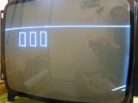
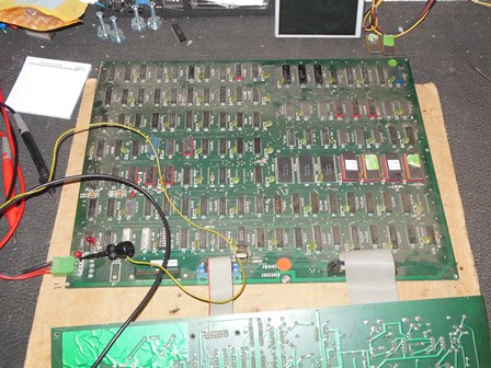
To simplify repair of the CCPU a bench power adaptor was built, needing only the +5V supply. The CCPU status LED appeared to be a good pre-requisite indicator that the CCPU was working at a basic level and not always needing the vector display.
|
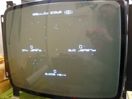
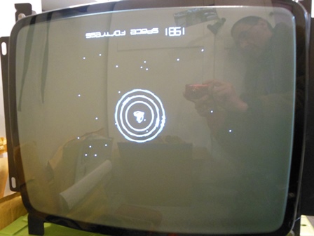
An internet search for hints on testing & repair of the Cinematronics CCPU found a simple Cinematronics RAM Test that was programmed into a pair of EPROMS (T7 & P7). The test was very basic but enough of a bare minimum to get an idea of RAM & vector output function.
|
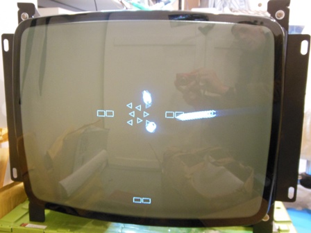
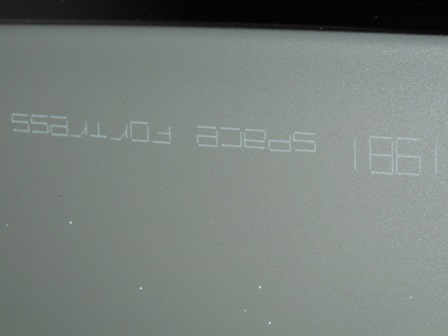
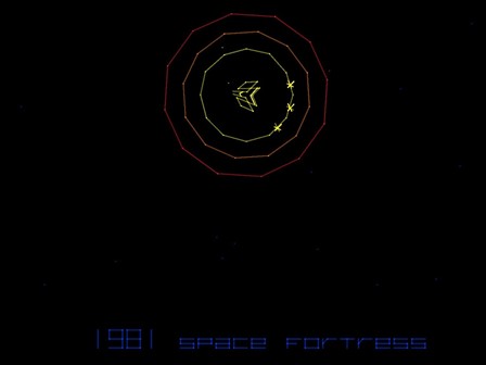
The Cinematronics RAM test ran & passed OK. I decided to dump the EPROMS and discovered that EPROMS R7 and T7 appeared to have runs of single bit errors. Replacing them brought the game to life with a working upside down attract mode.

|
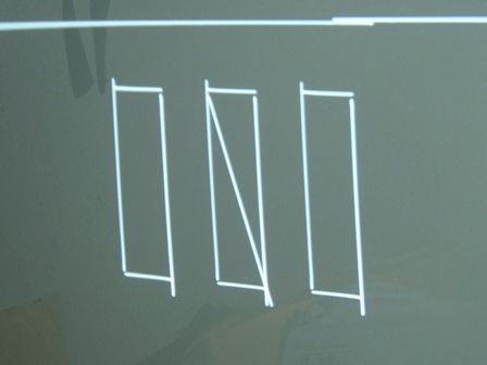
Some of the vectors were slightly misaligned, noticeable on the title text and ship. Some adjustment of the pots on the audio-DAC PCB improved the alignment slightly but the vectors were still misaligned compared to MAME. This issue would be investigated later.
|
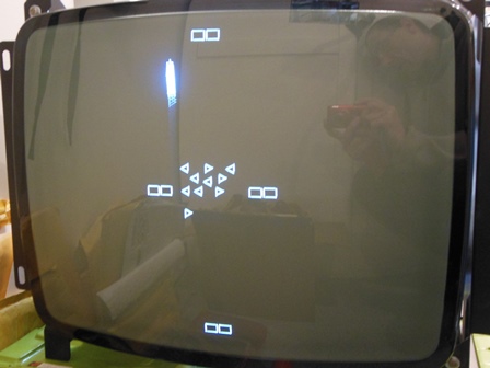
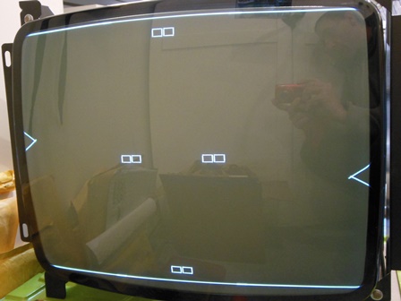
Using the Cinematronics RAM test ROMS flagged IC M14 (2101) as bad. Checking with a scope confirmed that all M14 inputs were active and all outputs idle.
|
Replacing IC M14 (2101) fixed the RAM test and both the game test mode and attract mode appeared to be working OK.
|
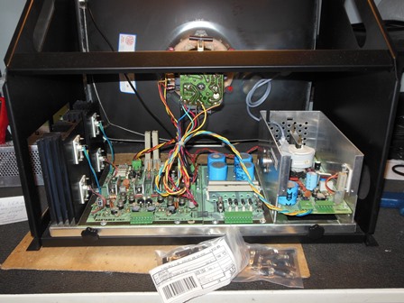
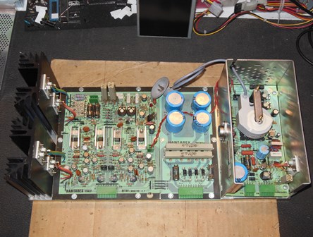
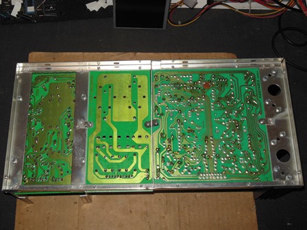
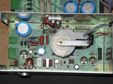
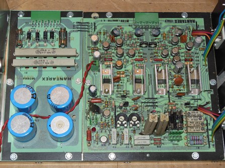
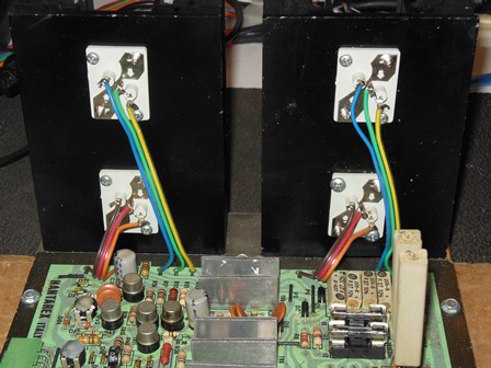
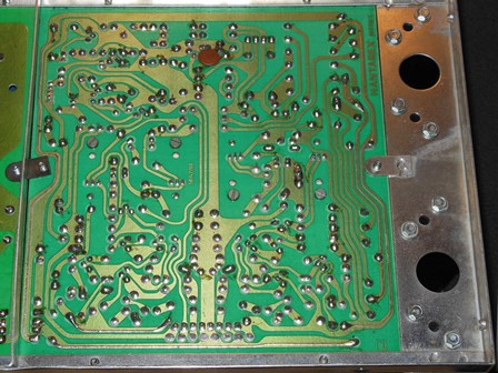
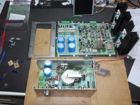
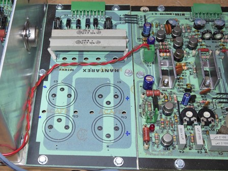
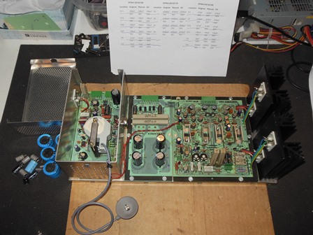
A few photos of the MTRV chassis were taken for the archive.
|
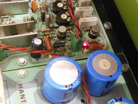
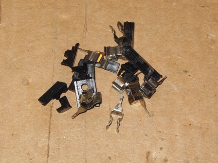
The monitor was New Old Stock (NOS) and had never been used but the fuses had corroded and the plastic of the fuse holders disintegrated when the fuses were changed. All of the fuse holders were replaced, and new fuses installed.
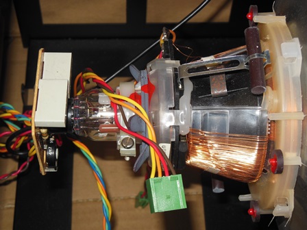
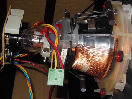
|
Bench testing the whole game had previously found the picture upside down. The yoke connector pins for both X and Y were swapped that should flip the picture right side up.
|
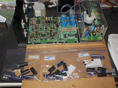
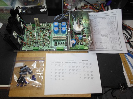
Three cap kits were made up correlated from the manual and the chassis. One was for this chassis and the other two for Space Pirate and a future spare chassis if another one surfaces.
| MTRV1 50142160 | MTRV2 50142170 | MTRV3 50142190 | |||||||||
|---|---|---|---|---|---|---|---|---|---|---|---|
| Location | Original | Manual | Kit | Location | Original | Manual | Kit | Location | Original | Manual | Kit |
| C11 | 100uF 35V |
100uF 35V |
100uF 63V |
C1 | 4700uF 35V |
4700uF 35V |
4700uF 160V |
C1 | 2.2uF 50V |
2.2uF 63V |
2.2uF 160V |
| C14 | 100uF 35V |
100uF 35V |
100uF 63V |
C2 | 4700uF 35V |
4700uF 35V |
4700uF 35V |
C7 | 470uF 35V |
470uF 35V |
470uF 50V |
| C20 | 100uF 35V |
100uF 35V |
100uF 63V |
C3 | 4700uF 35V |
4700uF 35V |
4700uF 35V |
C10 | 4.7uF 35V |
4.7uF 35V |
4.7uF 50V |
| C21 | 100uF 35V |
100uF 35V |
100uF 63V |
C4 | 4700uF 35V |
4700uF 35V |
4700uF 35V |
C11 | 100uF 16V |
100uF 16V |
100uF 50V |
| C6 | 2.2uF 63V |
2.2uF 16V |
2.2uF 160V |
. | . | . | . | C3 | 10uF 160V |
10uF 160V |
10uF 200V |
| C7 | 10uF 160V |
10uF 160V |
10uF 200V |
. | . | . | . | C9 | 2200uF 50V |
2200uF 63V |
2200uF 63V |
|
To access some of the capacitors on the high voltage PCB required the removal of the HV cage assembly. I also elected to replace the power supply smoothing capacitors as an additional reliability precaution. Everything was reassembled back into the monitor frame ready to install into the cabinet and retest.