Star Wars Restoration
Background
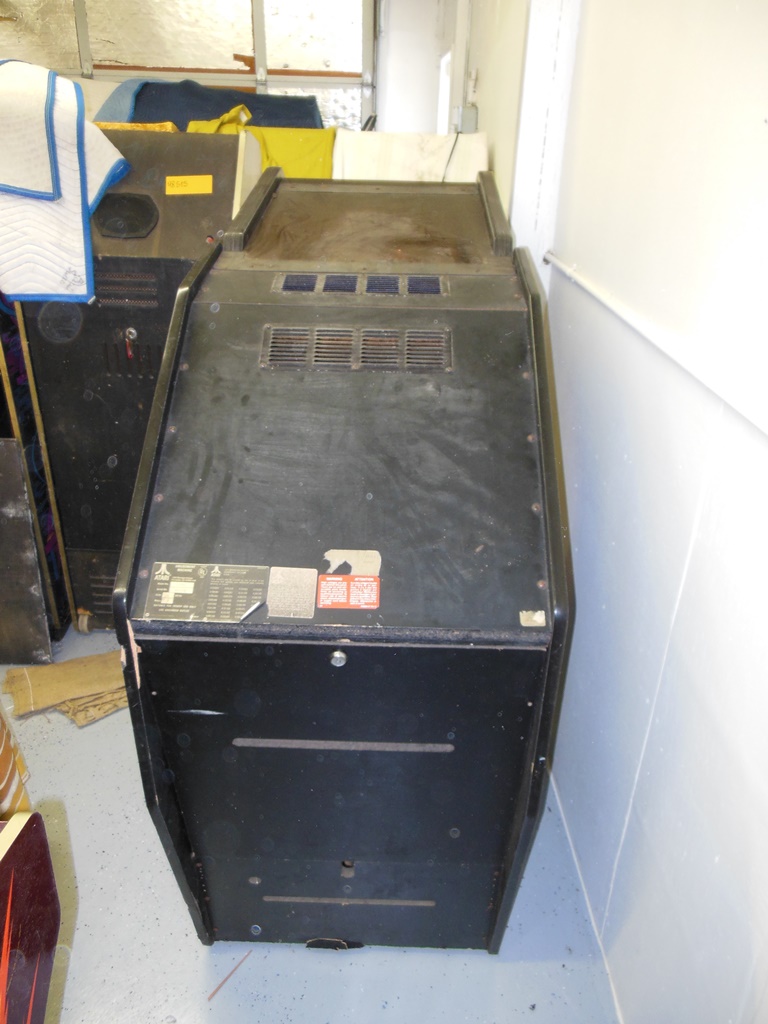
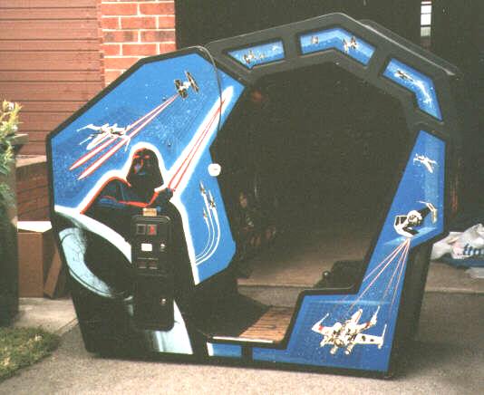
This game came from a closed used car dealership in the Suffolk/Norfolk area
during the 1990's. The cabinet itself was in excellent physical condition but
it had been converted to Konami GT and thus needed a significant amount of restoration
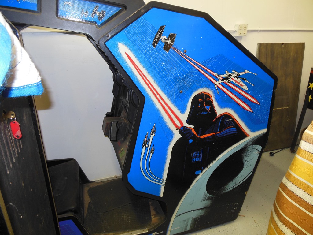
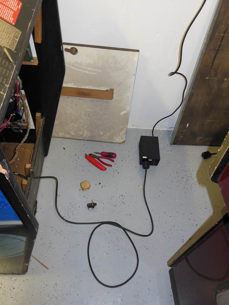
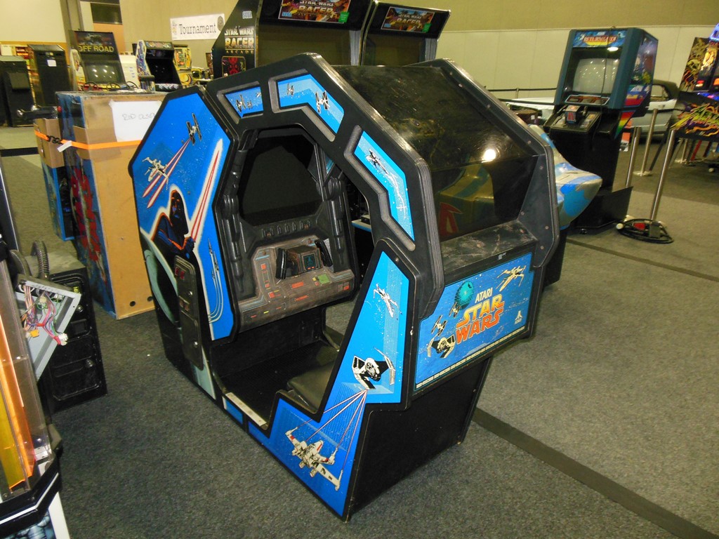
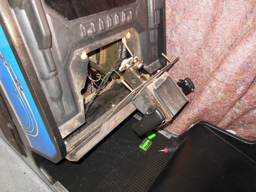
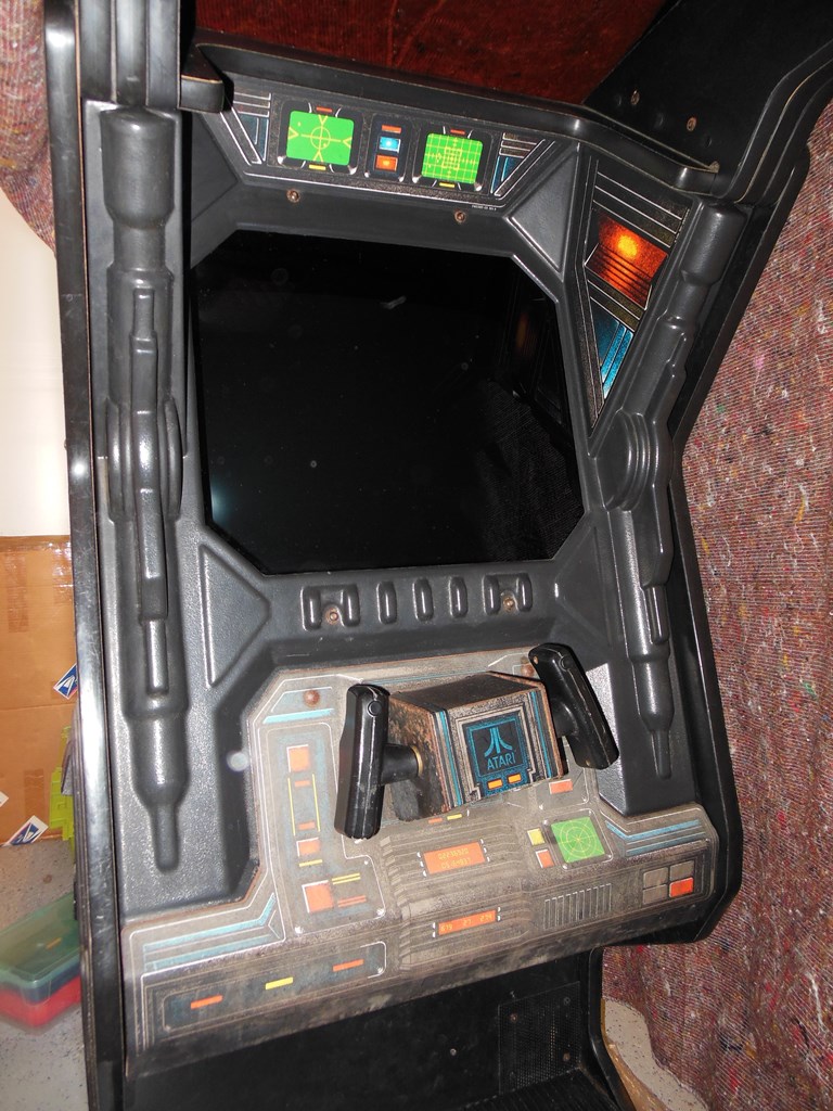
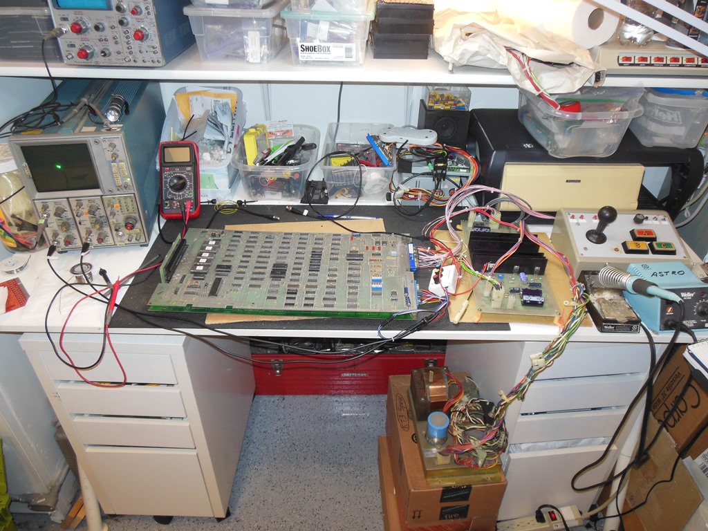
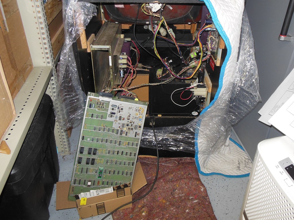
work doing to it. Below is a photo of it post unload after collecting it - note
the steering wheel, gear shifter and foot pedal.
In a stroke of luck, a fellow
UKVAC collector had most of the internals from a Star Wars cockpit obtained from
a travelling fair ground cab that was beyond saving and scrapped. I traded some boards
and other parts for those, that included a 25" Amplifone CRT, control panel and all
the wiring etc. Amplifone monitor boards were acquired from UKVAC/Ebay and three
sets of faulty Star Wars boards acquired from a small arcade stumbled upon during a
road trip through Canada. The main restoration work to get it back as a working Star
Wars happened during a six month break I took off in 2000 whilst waiting for my US
immigration visa. Thus, it had been in storage in the UK since then and came over
to the US with The Big Move.
I hadn't planned on working on it any time soon due to it's size and complexity,
however the 2014 Northwest Pinball & Arcade Show
put out a request for Star Wars games to compliment the attendance of the 501st Legion.
Thus it was a last minute scramble to dig it out, unpack it and get it running for the
show.
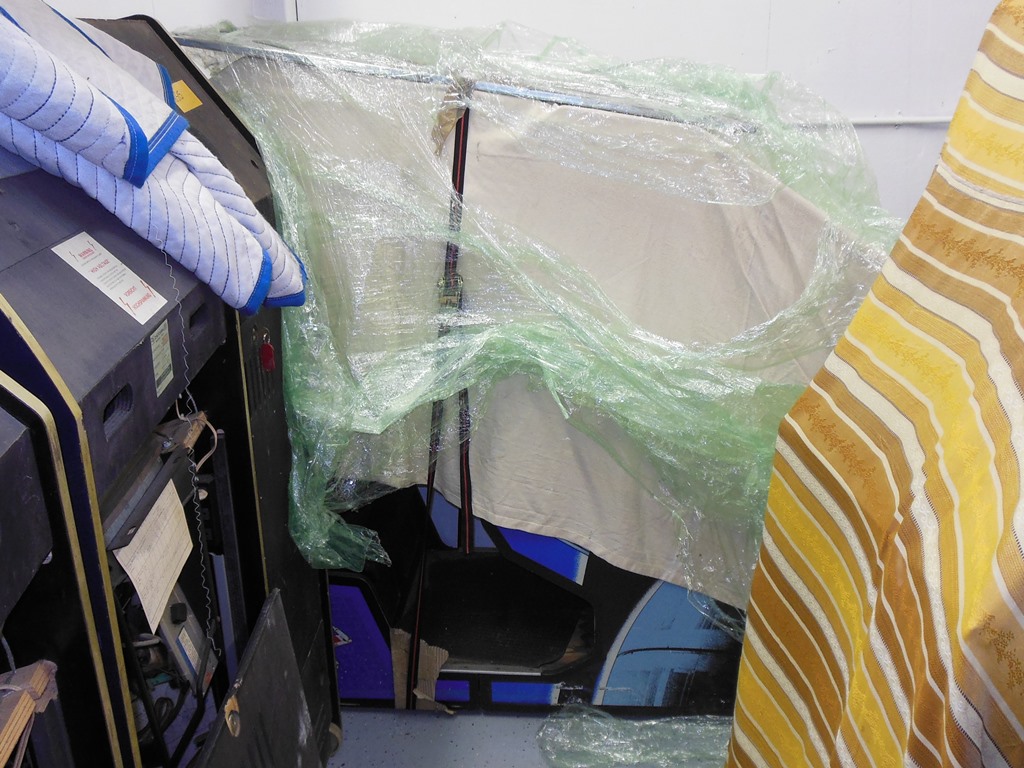
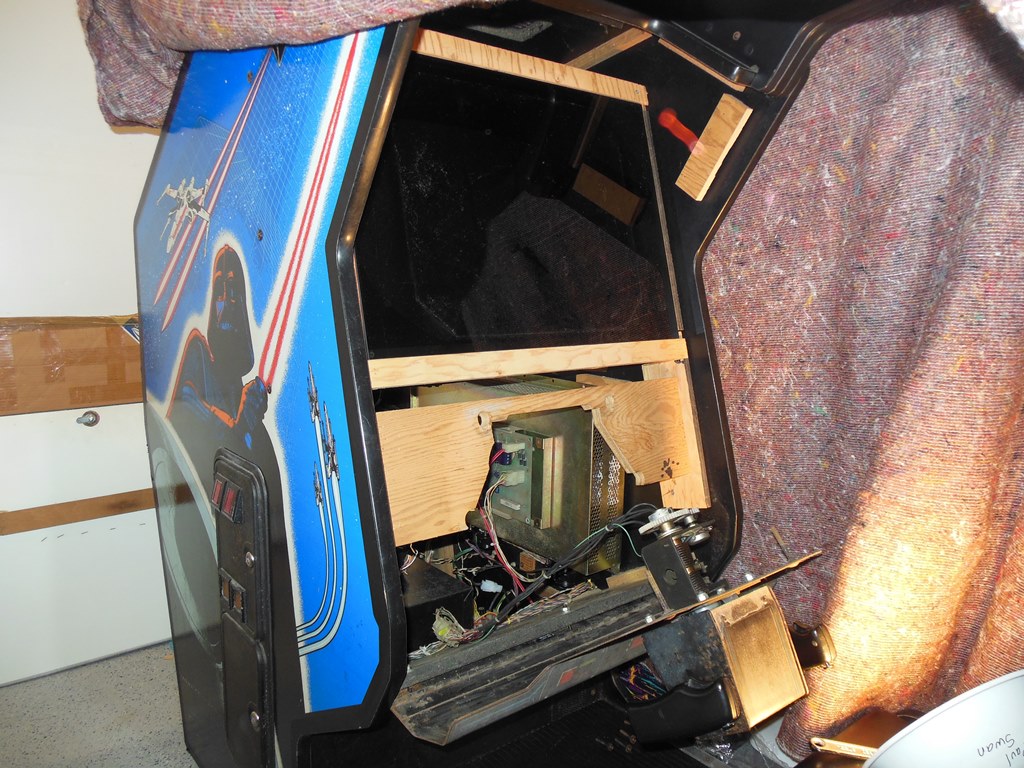
18/05/2014 - Unwrapped
The game was one of the last ones that was still all wrapped up from the Big Move.
It looked to have survived the ten years in storage plus the trip across the pond OK.
The last known operational state prior to storage ten years ago was that it
had developed a math box problem.
I replaced the UK style plug with a US style plug since the game can be easily
voltage adjusted with with right power brick plug.
Before first power on it became clear that my power brick had the wrong set
of voltage plugs on it (having 200V, 220V & 240V plugs). For the time being I used
a 110V-240V step up to get going. With power on there were at least two problems
to sort out.
Firstly, the boards were mostly dead except for occasional beep codes. I think once
they booted with vector chatter and the spot killer off for a short while.
Secondly, there was no HV on the monitor. Poking around with a multi-meter revealed
that at least one of the 24V regulators was bad on the HV board.
With only a few short weeks to the show it was going to be tough to get it going
without some additional help. I pulled the HV board and a local repair guy more setup
to repair them took it on and repaired it for me (luckily the LOPT was still good).
Another local repair guy familiar with Atari power supplies made up a 110V brick plug
to get it off the step-up. A local collector with a Star Wars upright not going to the
show loaned me his boards to put in it for the show.
01/06/2014 - Power on #2
With the HV board fixed and a set of loaner boards installed the game powered on
with life out of the monitor and audio/controls working fine. The blue gun appeared
to be on all the time and I suspected a fault in the blue gun drive circuitry on the
deflection board. The meter showed no difference between RGB drive output. Replacing
the blue drive transistor had no effect. I suspected that the blue gun may be bad
in the CRT :( There was no time to investigate further and off it went to the show
as-is (with permission).
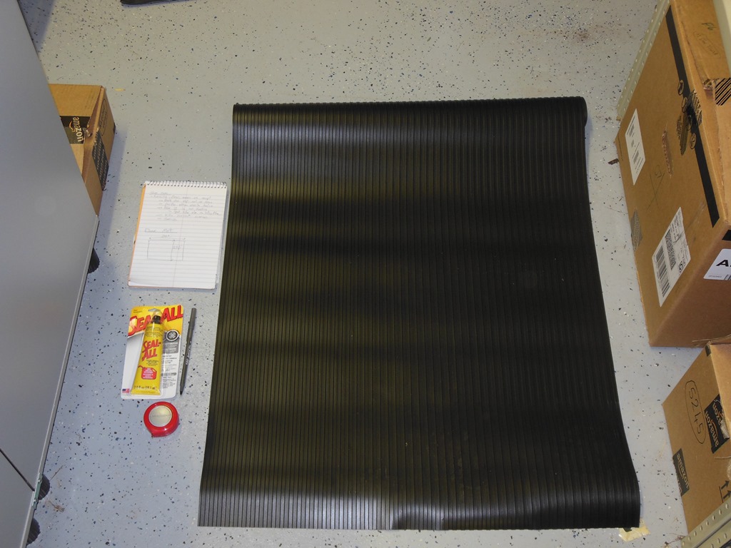
01/06/2014 - Floor mat
The cabinet was missing the original floor mat and had a temporary car mat
instead. For the show I bought a rubber mat to cut down and properly fit as a permanent
replacement.
10/06/2014 - Northwest Pinball and Arcade Show (2014)
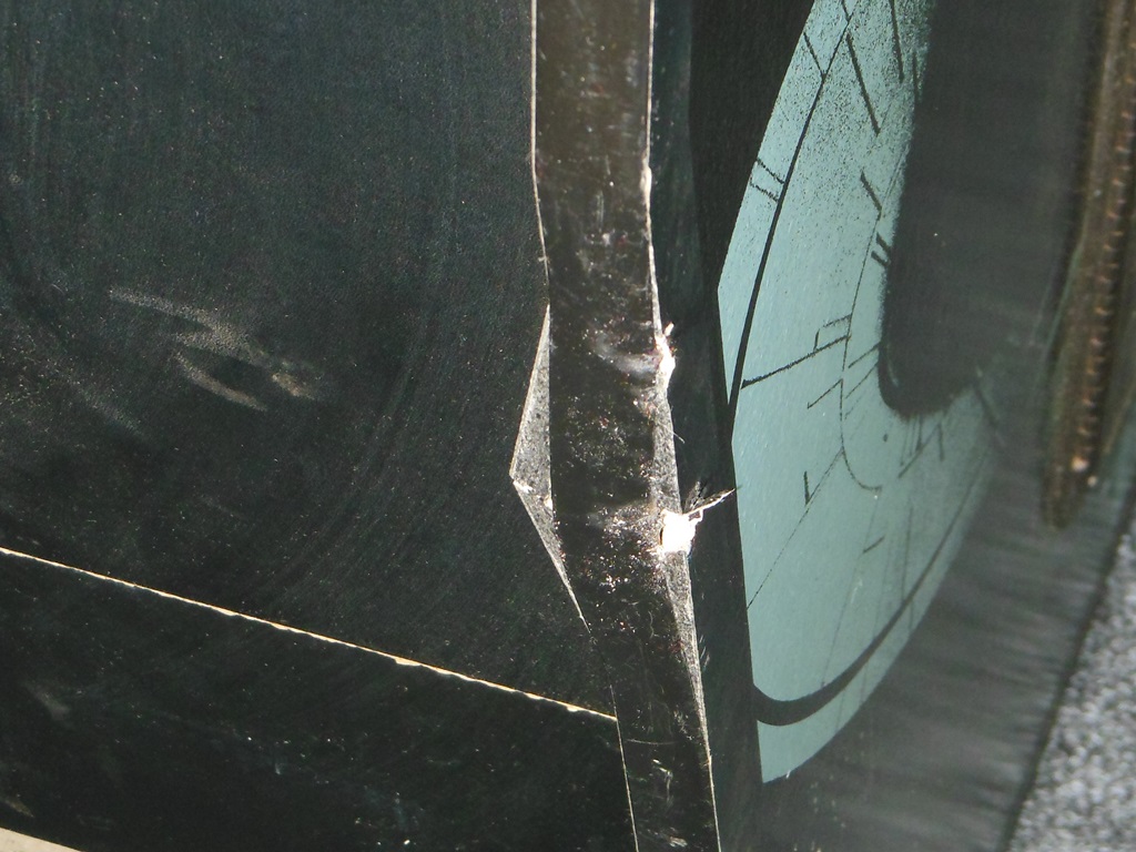
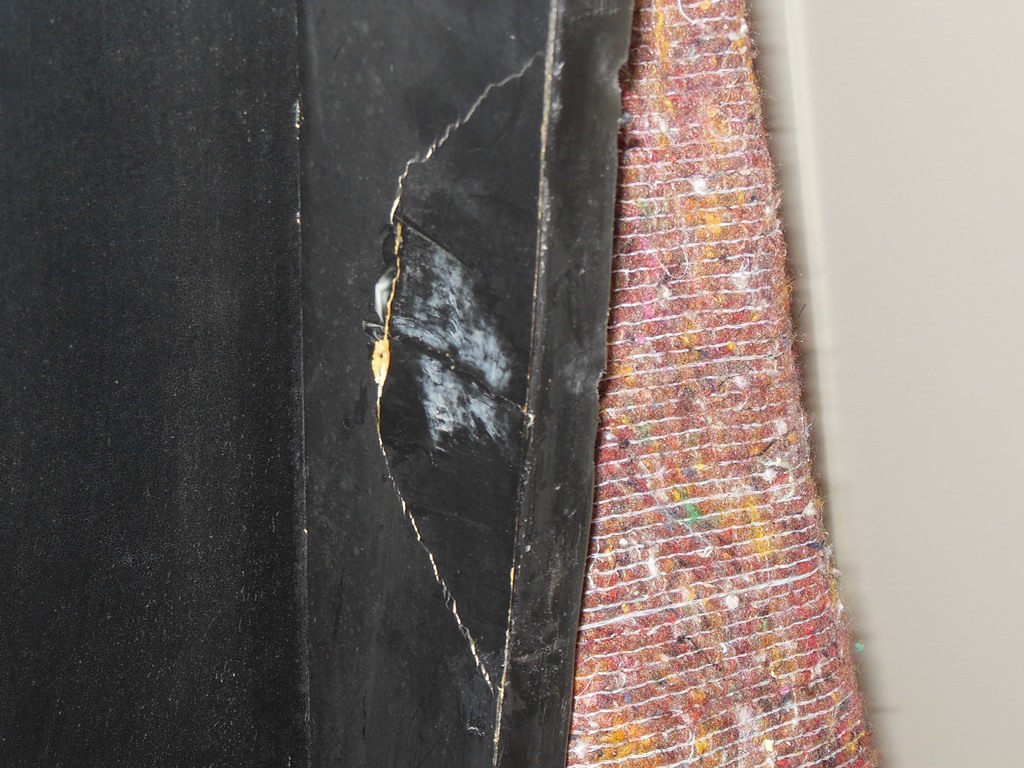
It got dinged on the truck from the ratchet hook that was hooked into the side
wall of the truck :( Only a small ding on the outside edge but it split the wall on the
inside edge. Aside from that it survived the journey in no worse shape with
the same blue gun issue but otherwise fine.
The show medics were able to rejuvenate the CRT and rebalance the guns and get a
reasonable picture out of it. The game ran fine all the way through to Sunday.
It was dead with a blank screen an hour or so before the show closed, which is
pretty good for a first time attendee.
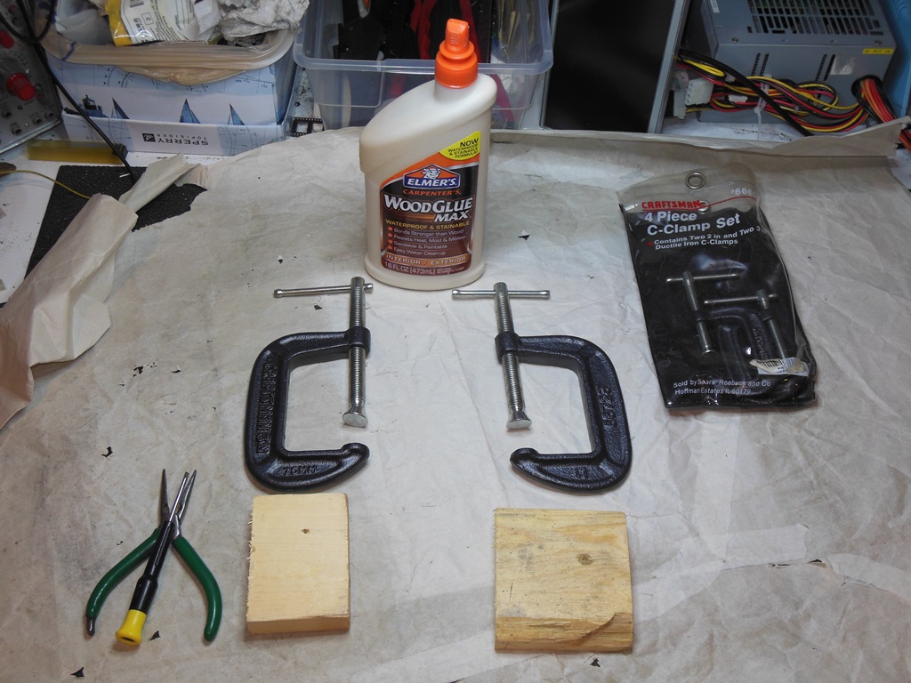
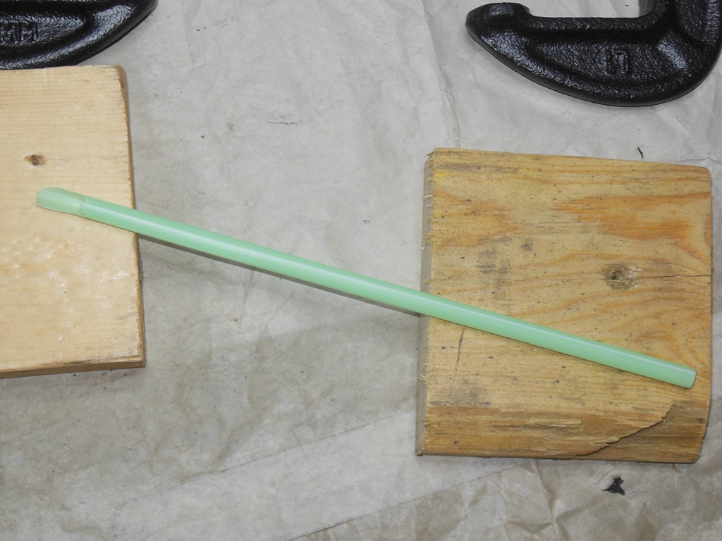
15/10/2014 - Side wall repair
The repair strategy was to use a straw to suck up the glue and inject it into
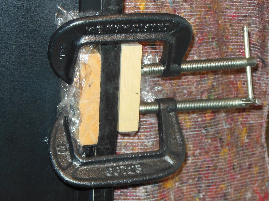
the split. Then use two wood pieces and G clamps to press the split back together.
A layer of cling wrap around the wood blocks would prevent them from getting clued
to the sides when the clamps forced out the excess glue.
The G clamps and wood pieces worked fine to press the split back together.
The resultant repair looks pretty good leaving only some minor filling and repainting.
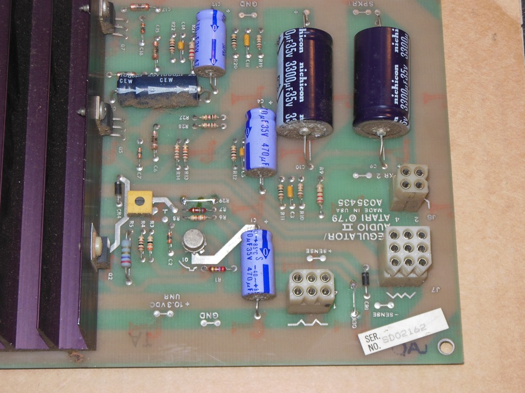
10/11/2014 - ARII sense mod
The "sense mod" as it is known has some controversy about whether it's needed or
not. I reviewed that material online and decided to do the mod for the following
reasons:
1) If the failure mode occurs it risks burning the ARII PCB that is permanent damage.
2) It allows the sense lines to supply power and thus spread the load accross 3 pins
instead of 2. This is the most compelling reason IMHO as it'll reduce the heat on all
the pins overall and likely extend the life of the connectors.
The sense mod itself is trivial - replace resistors R29 & R30 with solid wire links.
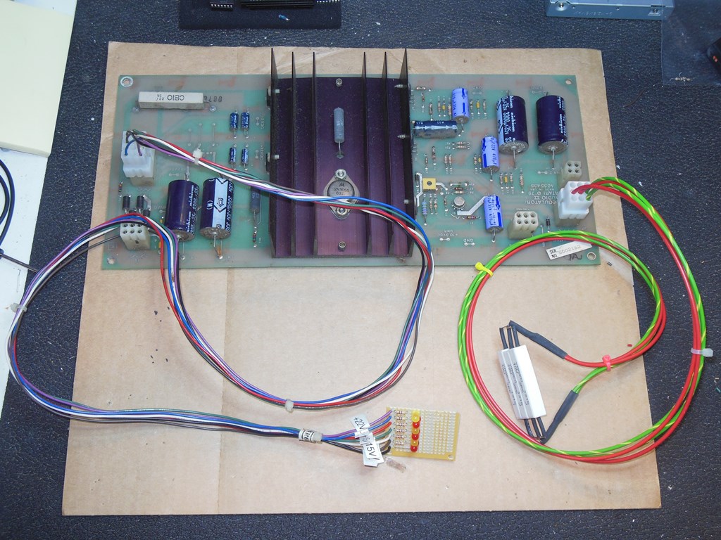
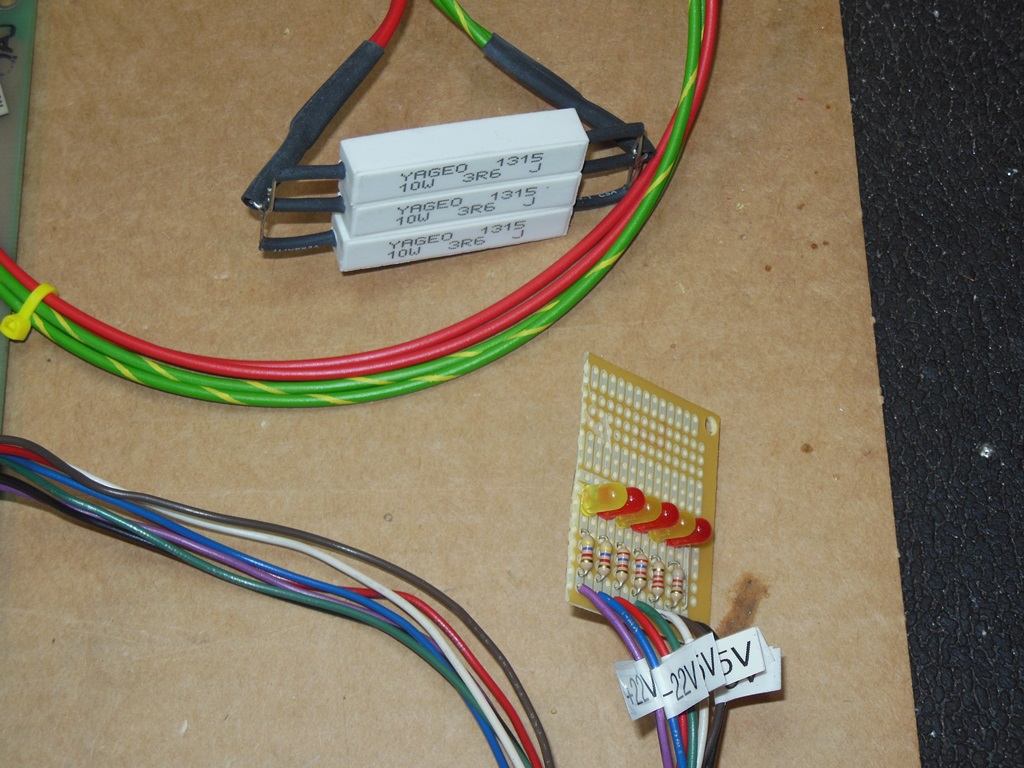
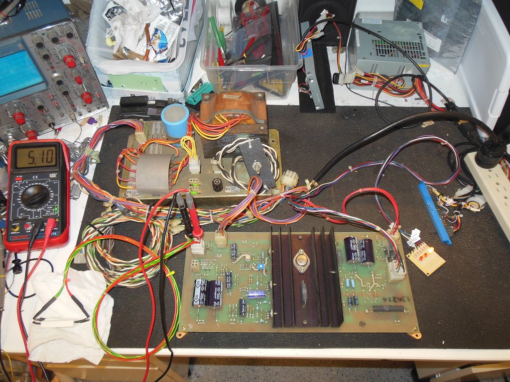
14/11/2014 - ARII test adaptors
Next up was to build a dummy load for the ARII +5V and a simple LED test adaptor
for the secondary voltages. The dummy load comprised 3 x 10W 3R6 resistors in parallel
(= 1R2 @ 30W), giving a current of 3.8A at 5V (= 19W power). The LED test adaptor
comprised a small PCB with simple standard LEDs attached to the six secondary voltages
with various resistors (~5mA):
- 22V 4.2K Ohm
- 15V 2.7K Ohm
- 12V 2.2K Ohm
- 5V 820 Ohm
On power on the +5V measured (without adjustment) exactly +5.00V (a first!). I adjusted
this to be 5.05V as a starting point but would adjust this again with everything connected
up and the board installed. The secondary voltages were all present and all measured good
except for the +/- 15V that were missing. From the Star Wars wiring chart it looks like
these are not used on Star Wars and the components are not populated on this ARII board
(that is a Star Wars cockpit edition).
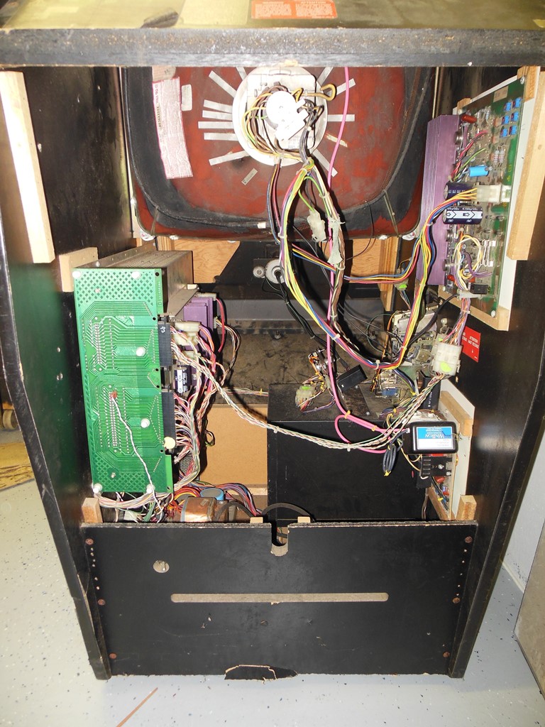
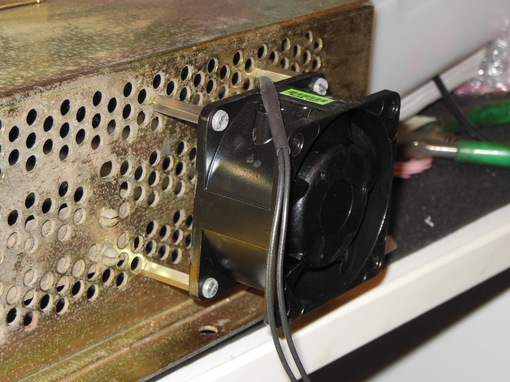
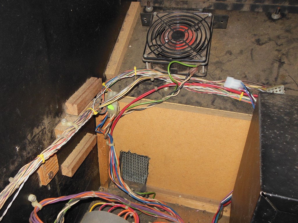
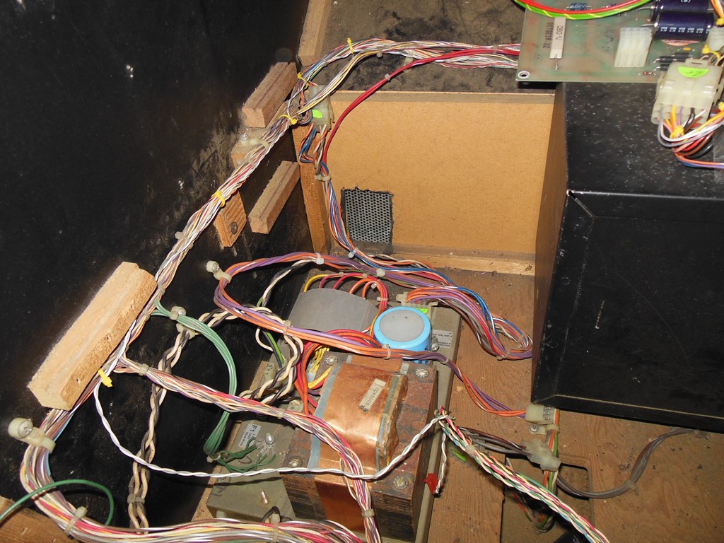
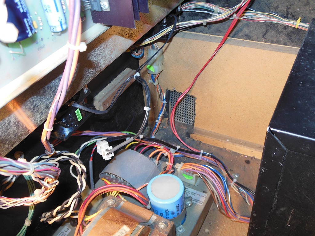
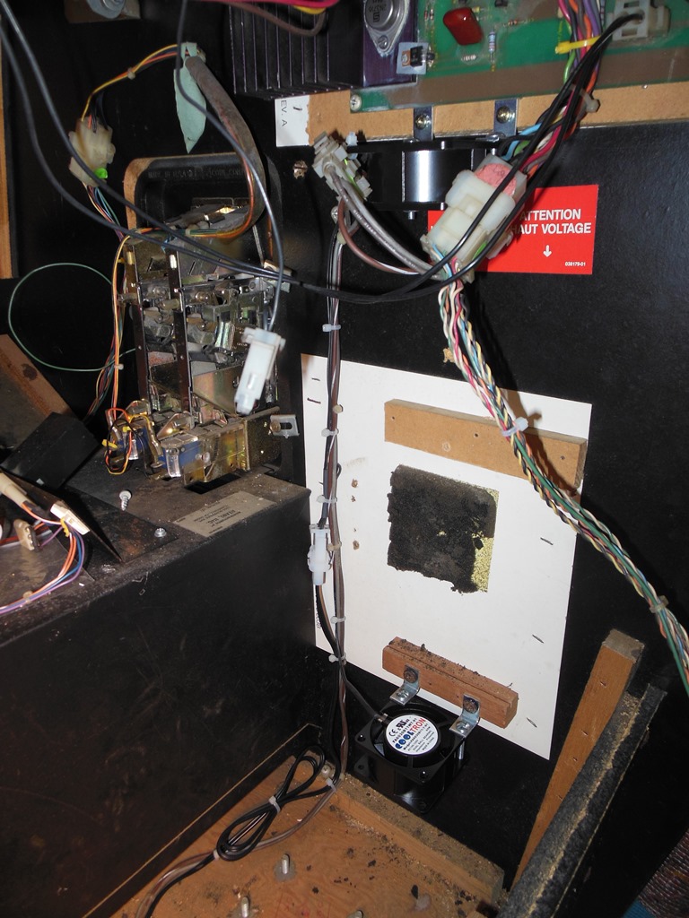
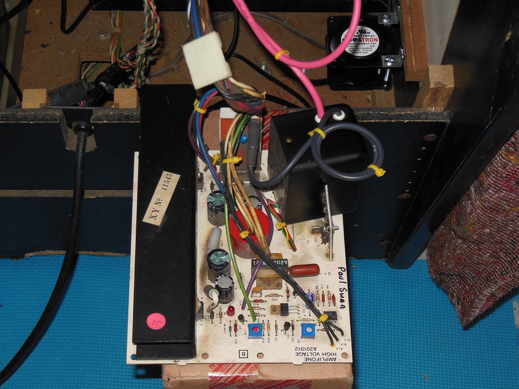
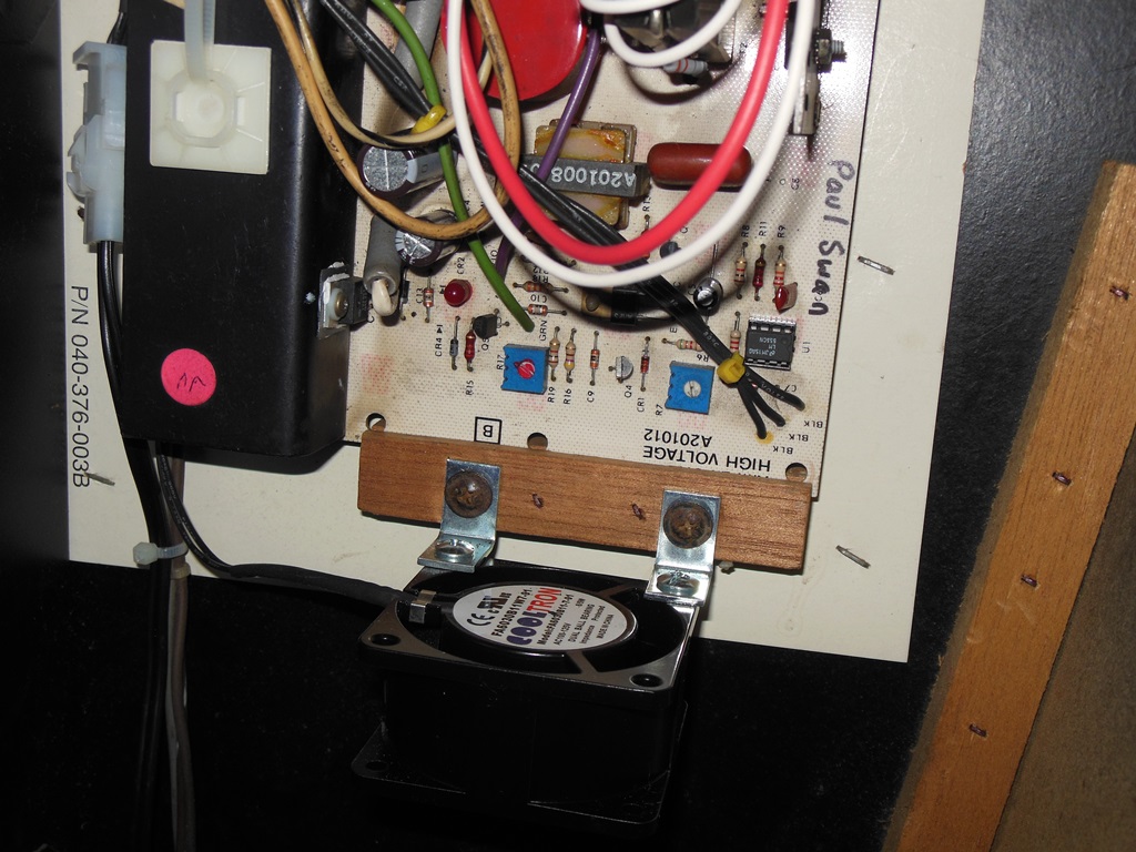
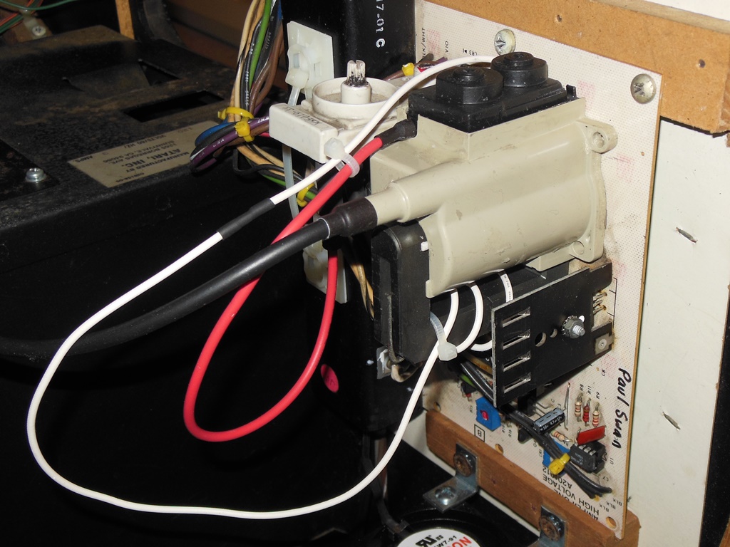
15/12/2014 - Fan upgrade
Originally the cabinet had a single fan in the corner blowing over the bottom
half of the game PCB cage. The hole in the base is a left over from the Konami GT foot
pedal that I covered with a fan grill as part of the earlier restoration as a repurpose
of the hole. To improve the reliability of the game as a whole the plan of action was
to remove the single large flan in the corner and replace it with four smaller ones -
two directly attached to the side of the game PCB cage, one under the Amplifone HV
PCB assembly and one under the Amplifone deflection PCB assembly.
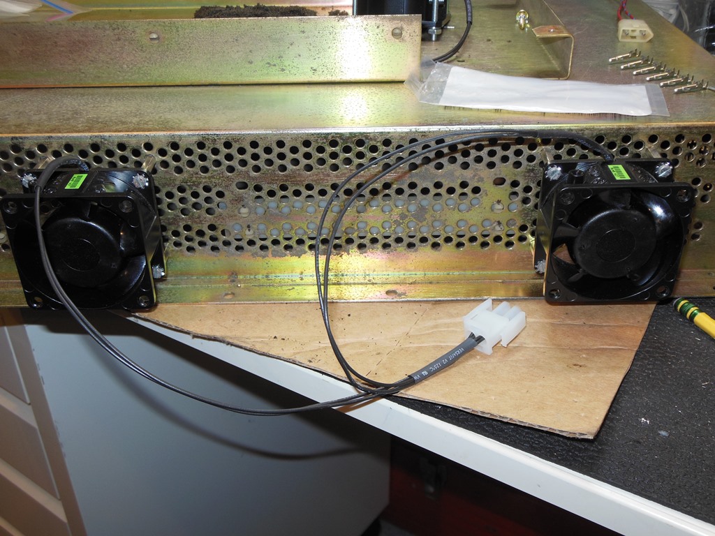
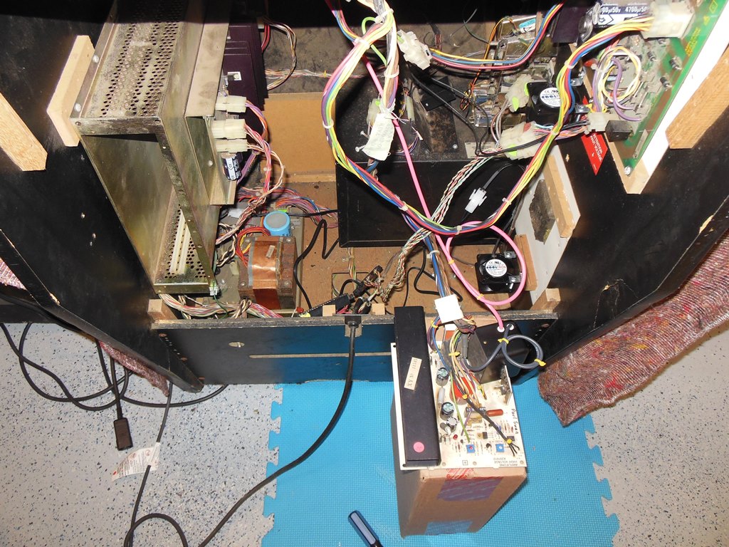
All four fans were the same - CoolTron FA6030B11W7-91, 100-125VAC, 60mmx30mm HS ball
bearing fans. I'd previously measured that they should approximately fit on the side of
the game PCB cage and in practice they were a near perfect fit, including the mounting
holes w.r.t. the holes in the cage. Not only that, the mounting holes for the fan also
lined up perfectly with the HV cage cover mounting holes so the only drilling needed was
a couple of holes in the deflection PCB card guide to mount the fan for that.
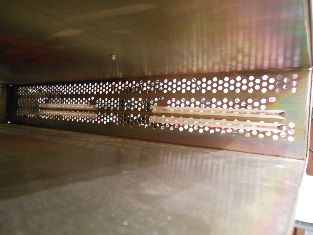
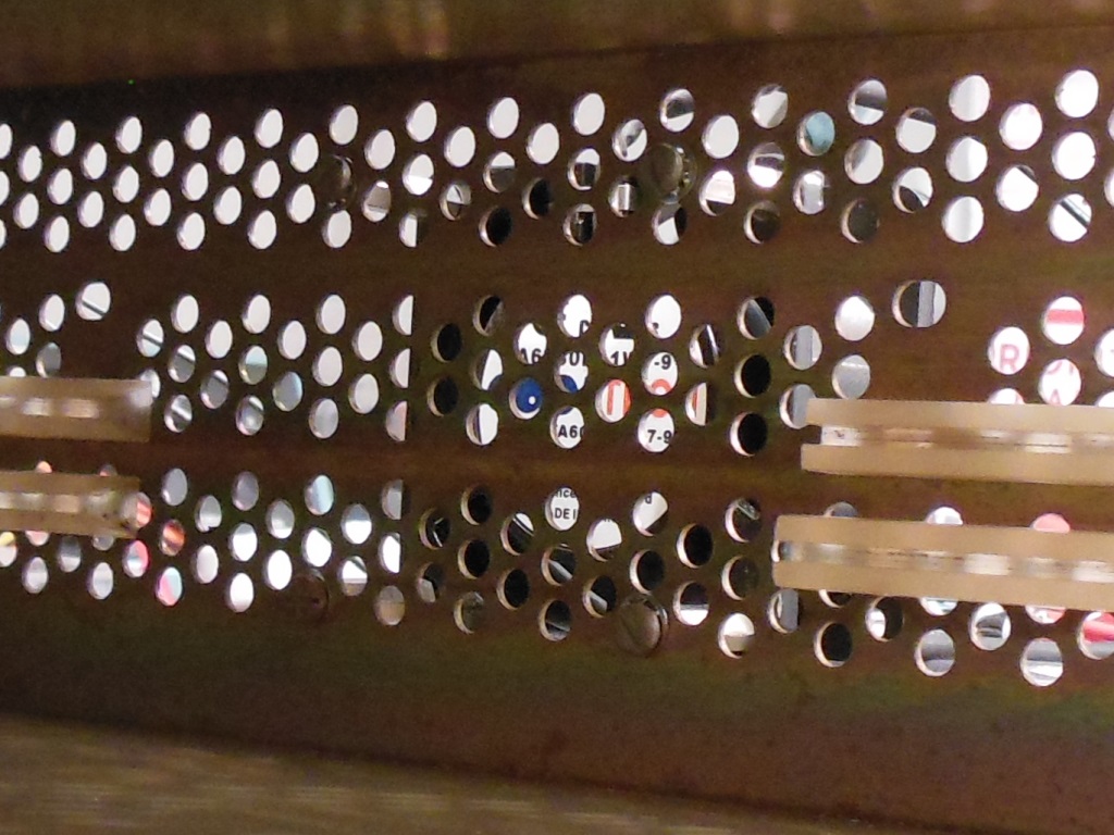
12/01/2015 - Game PCB cage fans
The game PCB card guides needed adjusting to remove the center portion and open
up the grill holes to allow airflow from the fan between the main CPU and vector
game PCBs. This was only needed for the center fan as the back fan was already clear
of the game PCB card guides.
The four fans were wired together in pairs and connected to the power brick
using a new section of wiring with a "reclaimed" matching connector for the power brick
so as to preserve the original fan assembly complete & intact. The original fan
assembly and wiring were separated out of the rest of the wiring loom.
14/01/2015 - Reassembly & tesing
Reassembly and power on showed the fans worked perfectly and were reasonably quiet.
There was a nice breeze flowing in the game PCB cage and over the two monitor PCBs.
There was a burning smell coming from the Amplifone HV board and on closer inspection
it was clear there was near through PCB burn mark under the 50Ohm bypass
resistor, a burn that was still occurring. Investigating with a multi-meter showed that
both 24V regulated supplied were 0V, likely short to ground and thus burning up the
bypass resistors :(
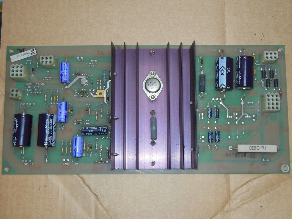
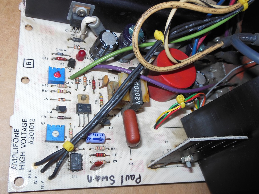
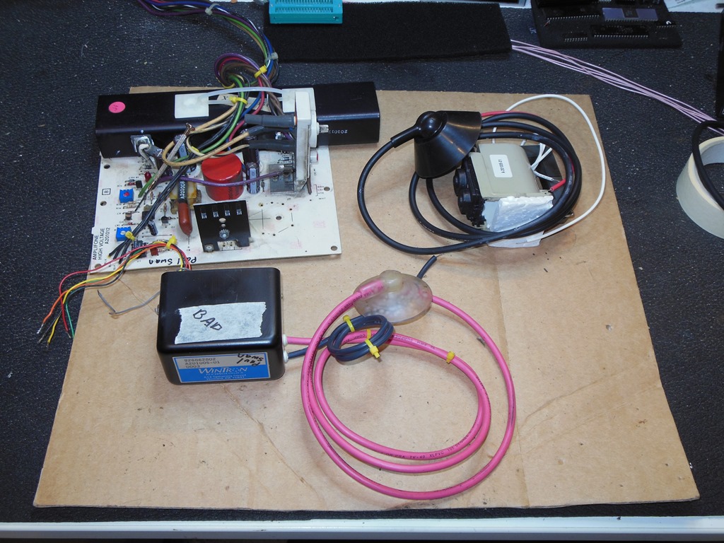
03/02/2015 - Amplifone HV rebuild
The plan was to simply replace all the main active components in the circuit and
also all the capacitors. I didn't buy any particular readymade kit since I had supplies
from prior repairs to use to make my own. The active portion of the kit comprised:-
| Location | Part | Description |
| VR1 | 7824 | +24 voltage regulator |
| VR2 | 7924 | -24 voltage regulator |
| CR1 | 1N914 | == 1N4148 diode |
| CR5 | 1N4001 | Diode |
| CR6 | 1N4001 | Diode |
| U1 | NE555
8-pin DIL socket | Timer IC |
| Q1 | 2N3904 | Transistor |
| Q3 | BU406D | Power transistor with diode |
I didn't have any MPS-U07 on hand but an in circuit test of it indicated it was likely OK.
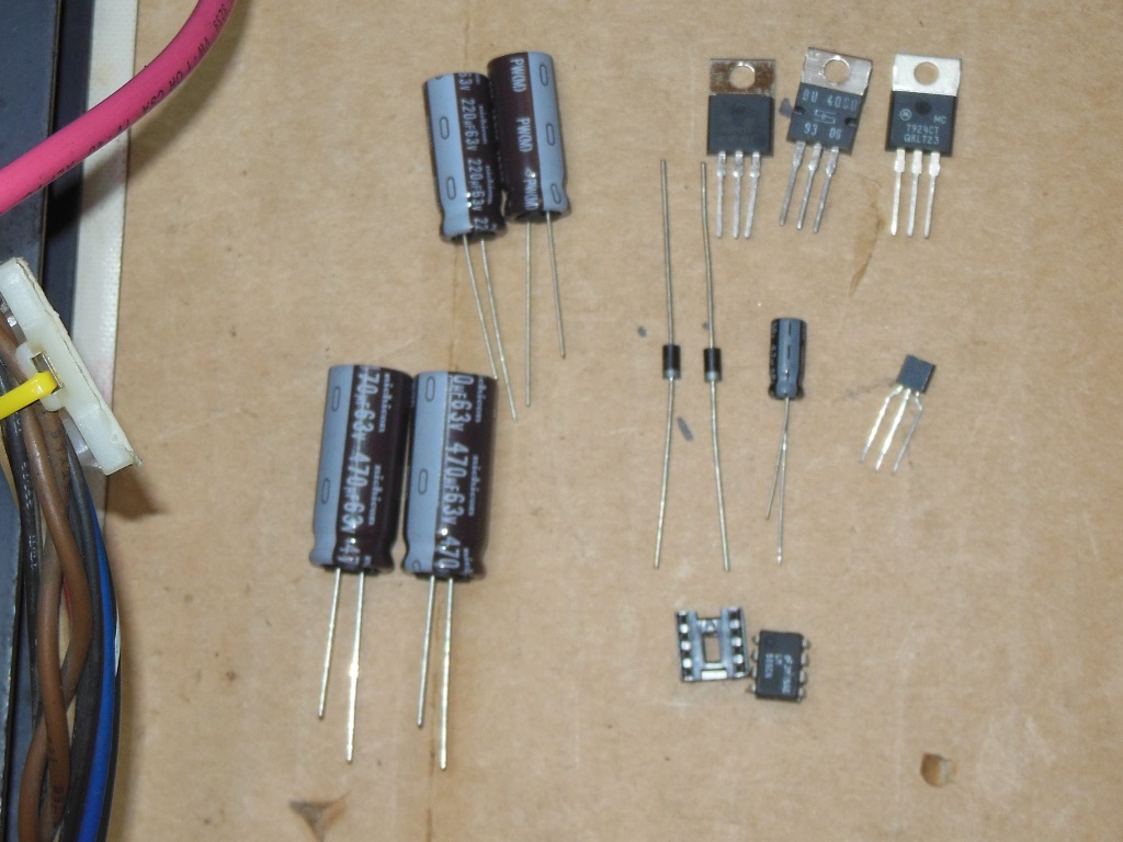
The capacitors:-
| Location | Original | Replacement |
| C1 | 470uF@50V | 470uF@63V/105C |
| C2 | 470uF@50V | 470uF@63V/105C |
| C3 | 220uF@35V | 220uF@63V/105C |
| C4 | 220uF@35V | 220uF@63V/105C |
| C5 | 4.7uF@50V | 4.7uF@50V |
Since the power capacitors are near the heat sink and power bypass resistors (hot
locations) I went with 105 degrees C rated replacements. I also deliberately used 220uF at
63V because if the +24V regulator fails the unregulated DC voltage slightly exceeds the 35V
rating of those capacitors.
Testing the replaced components identified that the 4.7uF capacitor was low at 4.0uF,
the BU406D and the 7824 was bad. The latter is a typical cascade failure in that
failure of the BU406D blows one or both 24V regulators.
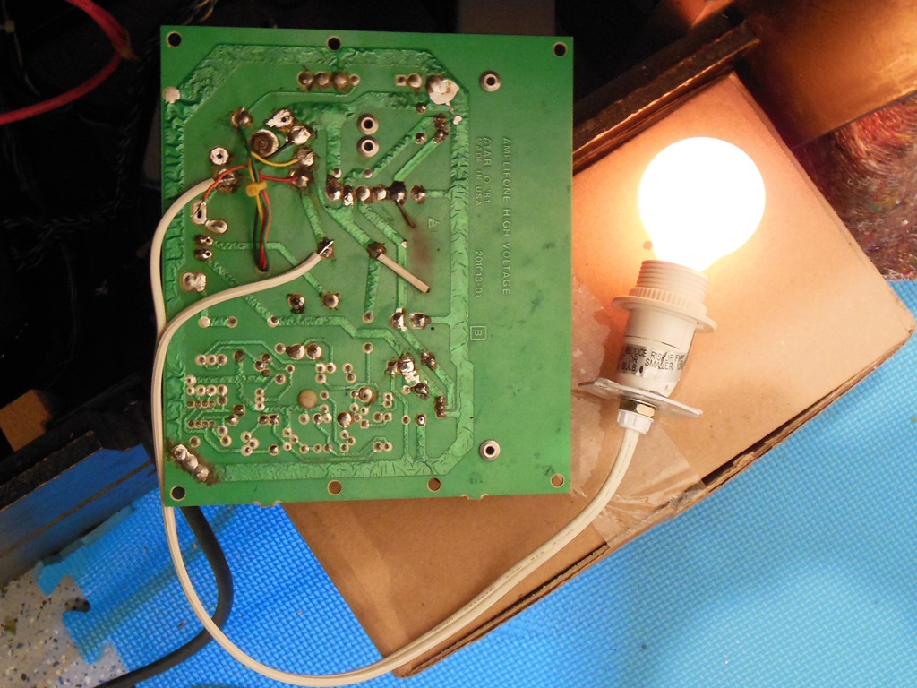
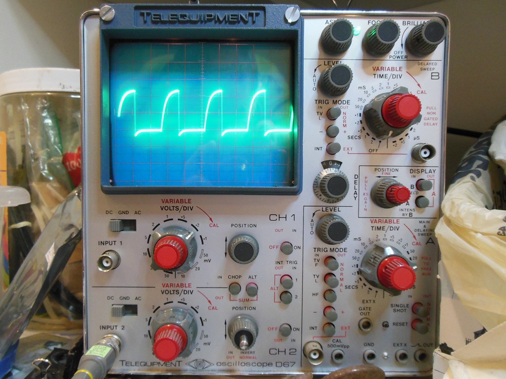
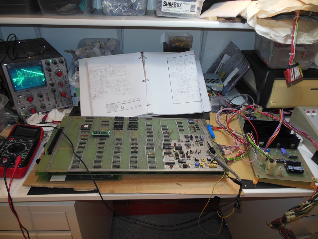
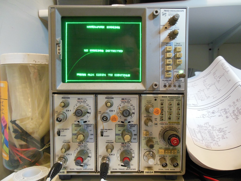
07/02/2015 - Amplifone HV retest
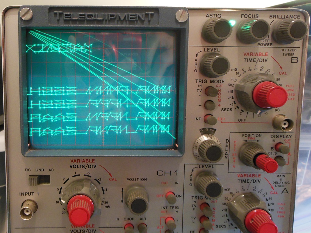
Reconnecting and power on still had no HV from the HV transformer and the BU406D was
getting hot quickly. Replacing the HV transformer with a 120V 60W light bulb dummy load
(across pins 1 & 9 with the HV transformer disconnected) and inspecting with an
oscilloscope showed a reasonable waveform (~48V switching square wave of ~20KHz).
In the above picture the scope is set to 20V/div vertical and 20uS/div horizontal.
This time around it looked like the Wintron had failed and I needed to order a new
Cinelabs replacement :(.
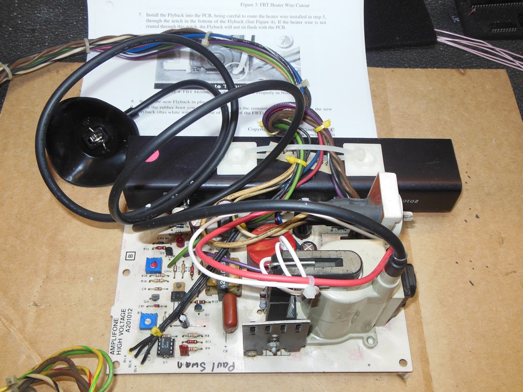
21/02/2015 - New Cinelabs HV transformer
The Cinelabs HV transformer arrived to replace the Wintron and fitted perfectly on
the board.
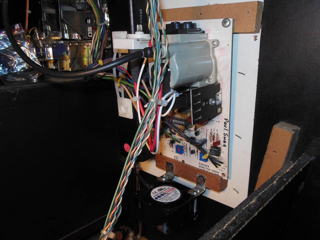
22/02/2015 - Monitor re-test
After fitting the HV board back into the cabinet and connecting it up it was ready
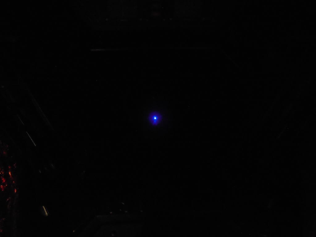
for first power on. No drama - just the crackle of HV, finally. Measuring with the HV
probe showed the HV running quite high at 22.6KV so I set the HV shutdown to hit just
about that and then reduced the HV to the recommended 19.5KV. A check on the screen showed
a blue dot (not full intensity, just a weak blue dot). This wasn't a surprise since this
CRT is not so great and has had previous problems with the blue gun not cutting off
fully. After a few minutes of warm up the blue dot faded mostly away.
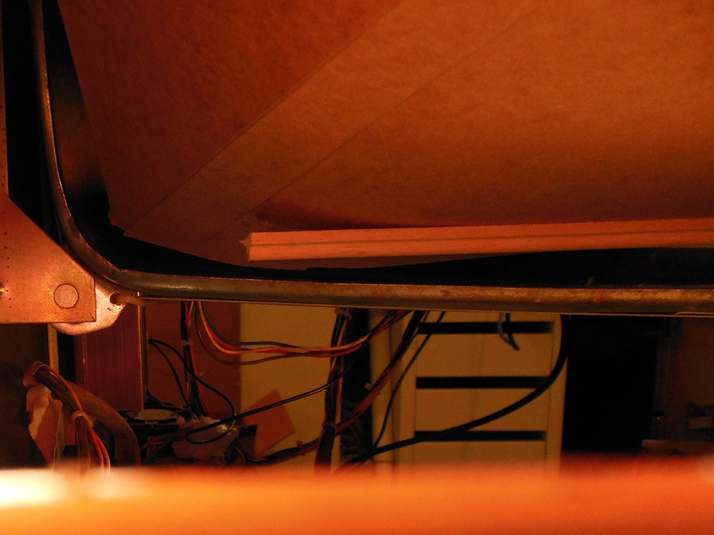
23/02/2015 - Monitor cleaning
In order to properly clean the monitor, front glass, surround and molding I
disassembled the whole front assembly (the molding is removable only with the control
panel open and the hinge bolts loosened to allow the control panel to drop further down).
The last cleaning was 10+ years prior as part of the main restoration so there was
mostly light dust and cobwebs to clean up.
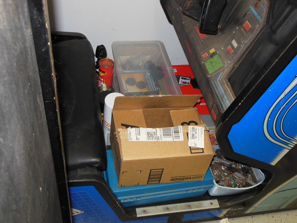
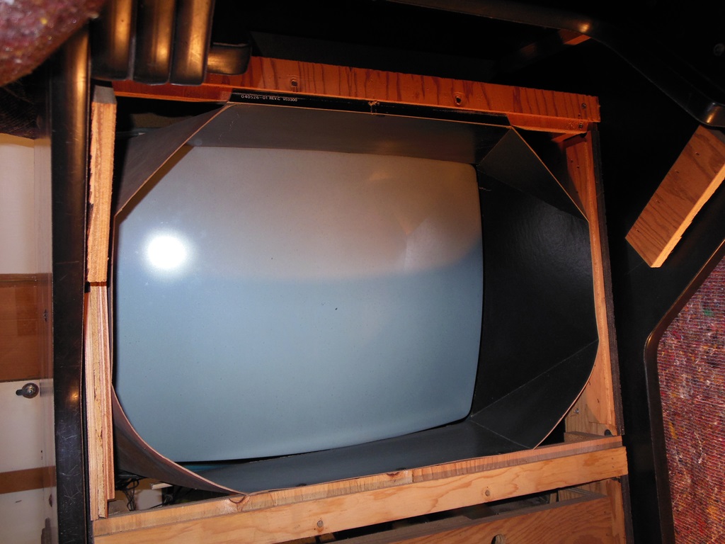
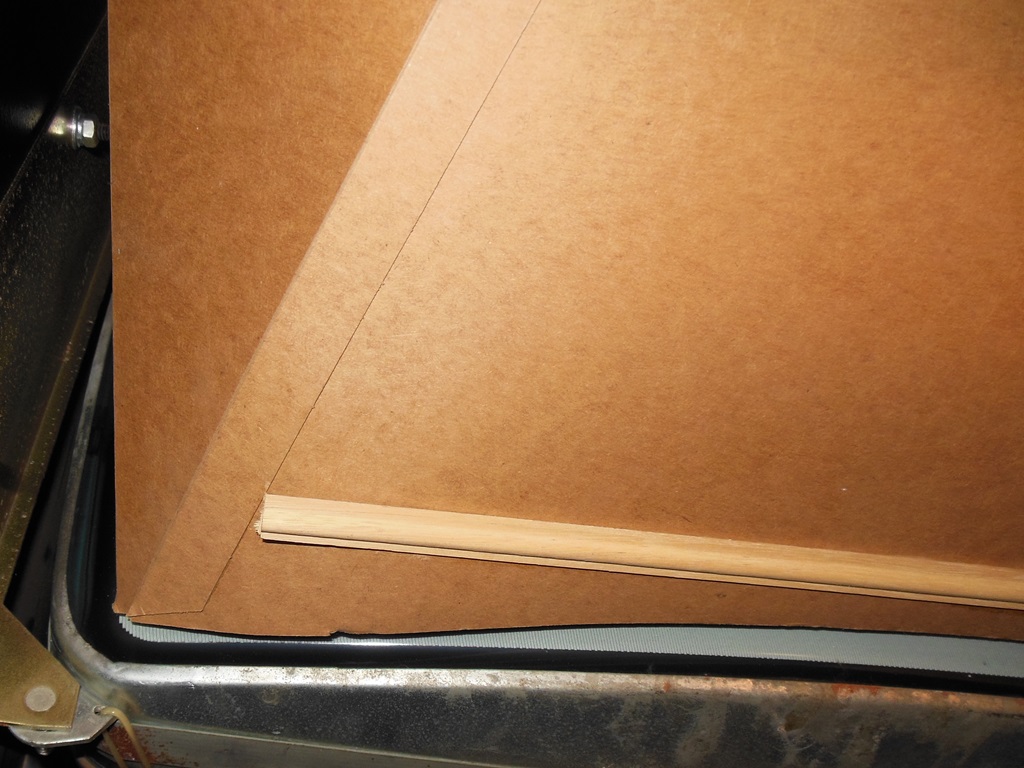
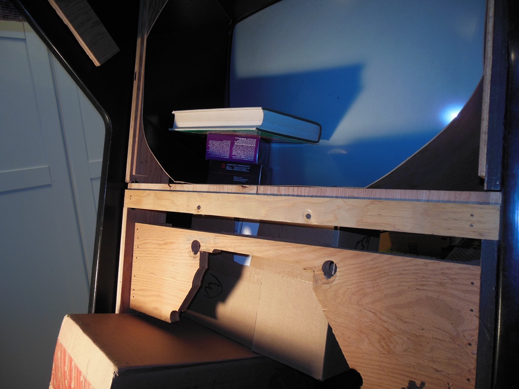
At the time of the main restoration I needed to add reinforcement wood strips to the
monitor surround to prevent it from sagging. One side of those had started to separate
slightly so I took the opportunity to re-glue it back in place using wood glue. The setting
was done with a pile of boxes on the bottom pushing it up and then a couple of boxes of
old floppy discs on top pressing down.
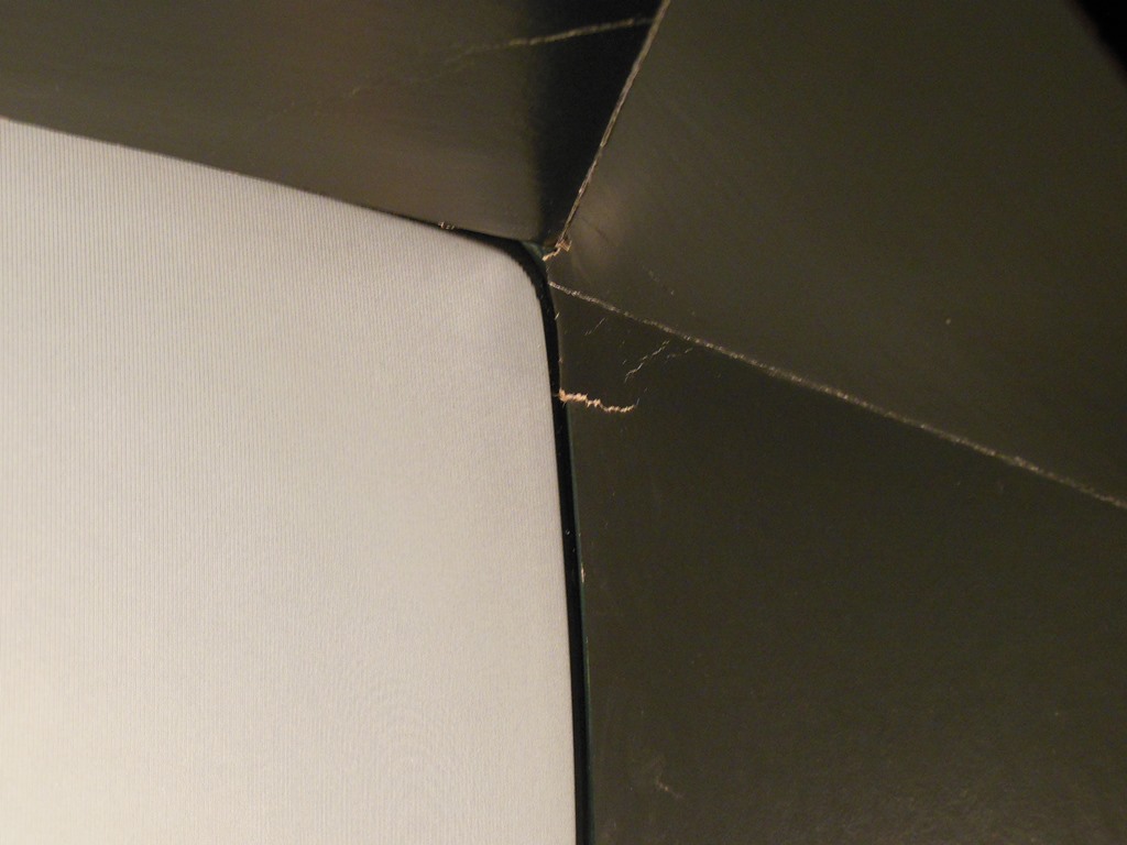
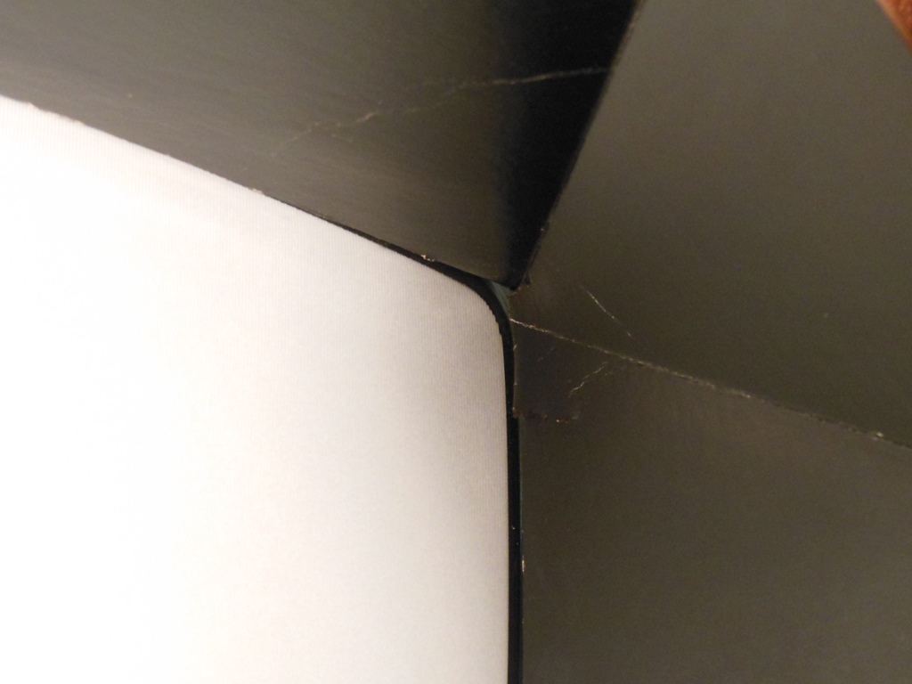
27/02/2015 - Monitor surround repairs
The monitor surround had some creases and small tears here and there that were easily
hidden with a black Sharpie permanent marker. The tinted glass hides these minor
imperfections entirely.
The CRT has prior spot burn damage in a couple of places that's mostly not
noticeable with the tinted front glass in place.
08/03/2015 - Interior reassembly
I cleaned the surround & glass prior to assembling them back into the cabinet.
The yoke cleaned up a little bit but was in need of a full strip down, repaint and
new overlay. The control panel overlay is complete and untorn but faded. I decided
to leave these as is for now.
The restoration paused here pending the return of repaired game boards...
25/04/2015 - Game boards arrive
The repaired game boards arrived back and were fitted back into the cage in
the cabinet.
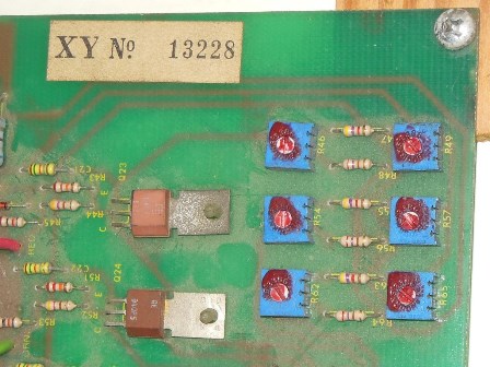
01/05/2015 - Power on & monitor adjustment
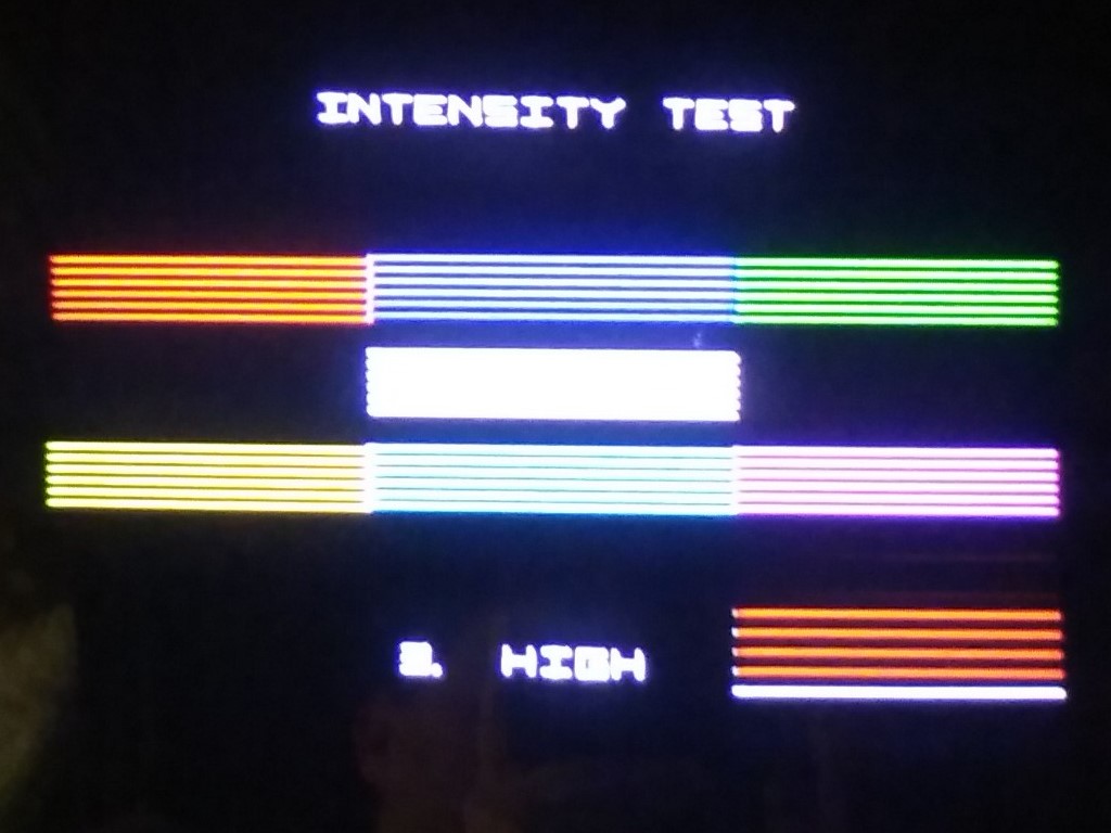
First power on yielded an odd center spot on the monitor but the
game boards themselves passed self-test. The intensity test showed the monitor
was in need of adjustment.
Most of the adjustments could be made using the six pots on the deflection
board once a baseline screen setting has been established. The procedure is
nicely documented in the manual packet.
After adjustment the picture was pretty good aside from the center spot artifact.
11/05/2015 - Center spot investigation, part 1
No amount of tweaking of the screen and deflection pots had any effect
on the center spot. The next idea to try was to tweak the HV to see if that
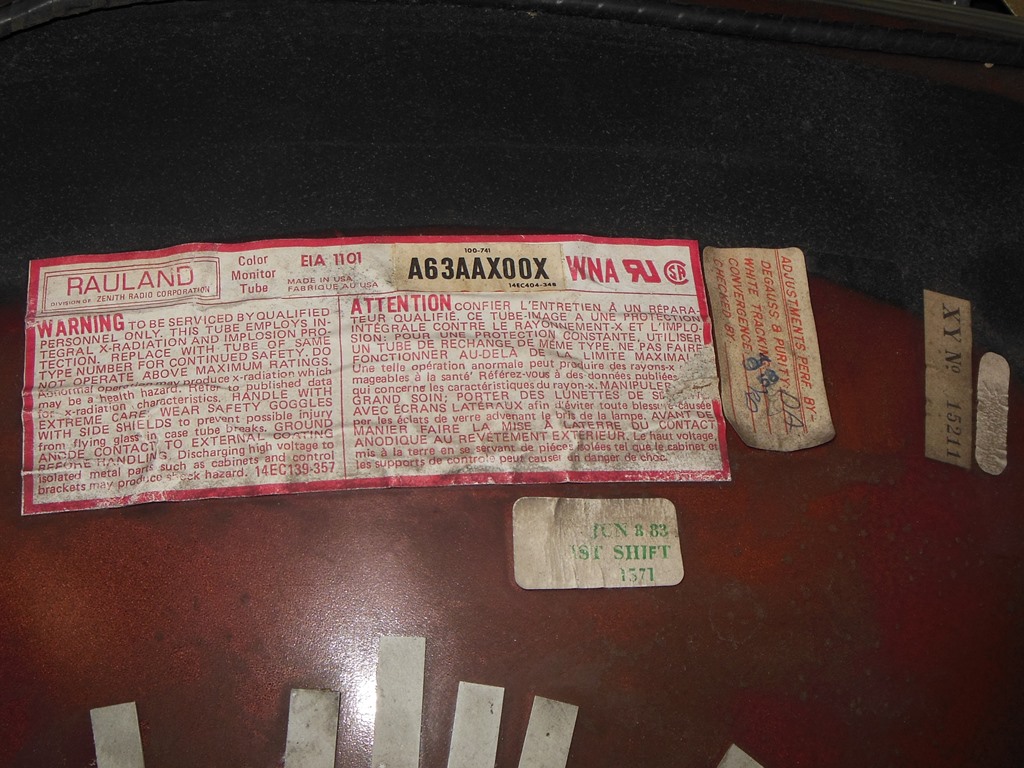
made a difference but it also had no noticeable effect. I was beginning to
think that the tube was bad and I'd need to find another Rauland A63AAX00X. :(
14/05/2015 - Board failure
A few days later the game failed to boot and the self-test beep code 4 indicated
a bad RAM on the AVG board at location 3L. The original was an Am9128-15PC that is
equivalent to a standard 6116-2 type.
Replacing RAM 3L (6116-2) fixed the board and the game was back working again.
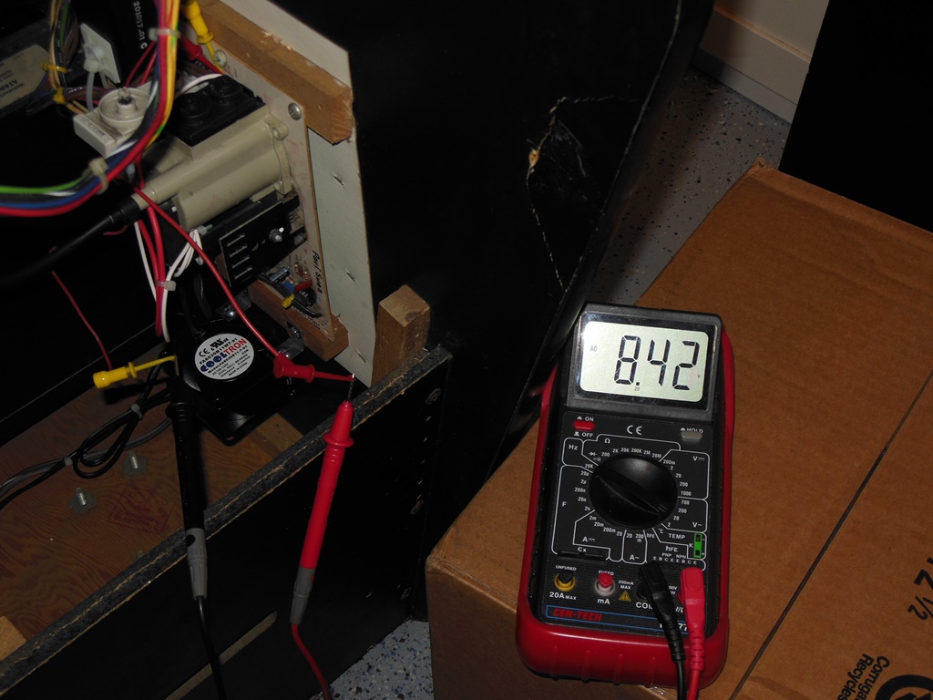
16/05/2015 - Center spot investigation, part 2
A little searching around the web yielded a small two-line KLOV posting that mentioned
to check the number of turns on the Cinelabs heater wire winding and to take off one
turn. I checked the heater voltage and sure enough it was over-voltage 8.42VAC.
Removing one turn to leave two complete turns instead of three reduced the voltage
to a proper 6.33VAC. Finally the center spot was drastically reduced to a dim
shadow. Further, the drastic colour imbalance problem was also much reduced and the picture
looked good :)
16/05/2015 - Board failure, again
After a couple of hours of testing there was no picture and the spot killer was on.
Self-test didn't indicate any beep code errors and attention turned to the XY outputs.
Poking around with a scope showed that XOUT was active but YOUT was high. The Y DAC (Am6012)
output was all over the place but as a current output device it was supposed to be a steady
line. Recommendations from fellow VAC'ers with more experience on this platform suggested
that the op amps and/or analogue switches were bad on the output of the DAC and to
change those first before suspecting the DAC.
Changing the op-amp and analogue switch brought the picture back and fixed the game.
16/05/2015 - Board failure, again
After a another couple of hours of testing there was mostly no picture again,
mixed spot killer and a few odd vectors floating around. Pulling the board out
again and poking around with the scope revealed a bad YOUT again. The Y DAC (Am6012) pin
18 showed some pulses and the YOUT was all negative. YREF was supposed to be steady
state but was all over the place. Since this was shared via passive components with
XREF that was perfectly steady it appeared the Y DAC (Am6012) had failed affecting
YREF
Changing the Y DAC (DAC312) brought the picture back and fixed the game. The new
DAC needed a readjustment of the Y BIP.
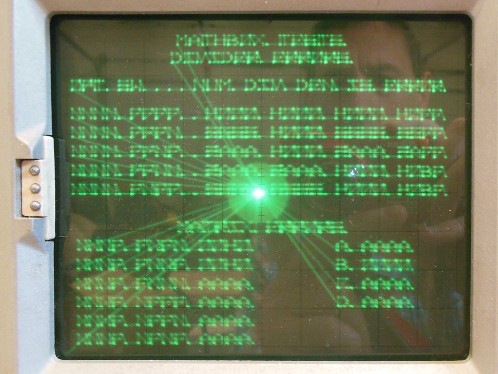
23/05/2015 - Intensity problems
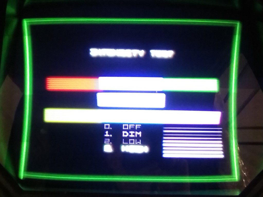
After another couple of hours of testing the fade out of the story text & scores
etc. became choppy and it looked like a low order bit of the intensity was stuck. This
was more clearly shown on the intensity test screen where DIM is brighter than LOW.
The intensity in general had become overly bright and needed re-adjustment.
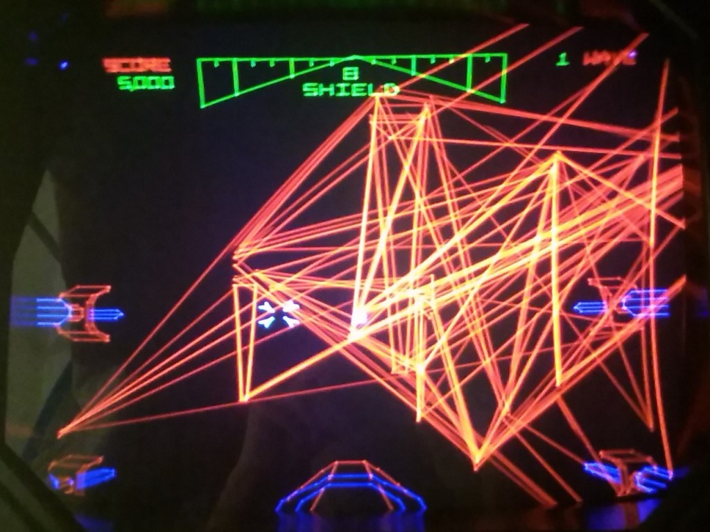
23/05/2015 - Another board failure
After another three or so hours there was no picture again with no XY output
other than a slow moving dim dot. Investigation of the board showed most of the AVG
board idle with no active outputs from the AVG custom IC. We suspected AVG custom
failure. I ordered a reproduction FPGA replacement off Ebay :(
27/05/2015 - More board problems & board failure
A local VAC'er loaned me a couple of AVG customs to try and get the game going
for the Northwest Pinball & Arcade Show. Replacing the AVG custom brought the game
back to life but with some more problems - the matrix processor was now showing errors
(and thus the vectors were all over the place) and all intensity control was gone (even
with screen and all the deflection pots turn all the way down the screen was still too
bright and only showed on/off colours).
After another couple of hours there was no picture yet again. There
was no spot killer and XY chatter so I suspected RGB output or intensity failure.
The game was officially withdrawn from the 2015 show :(
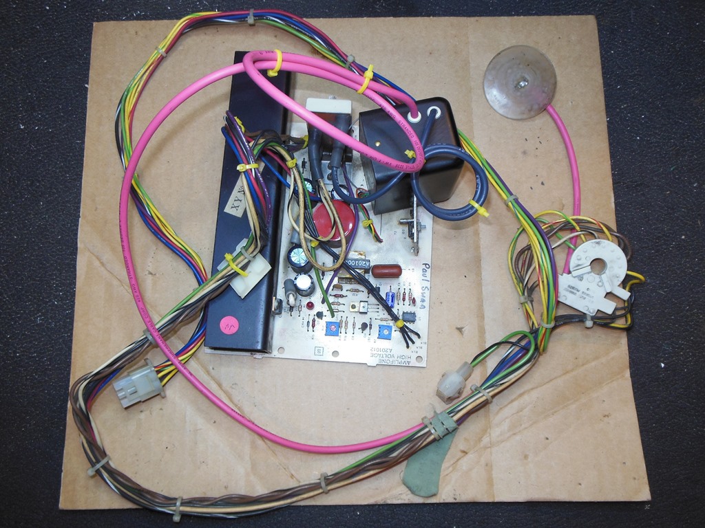
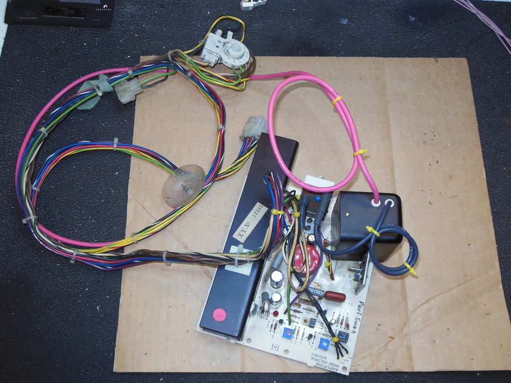
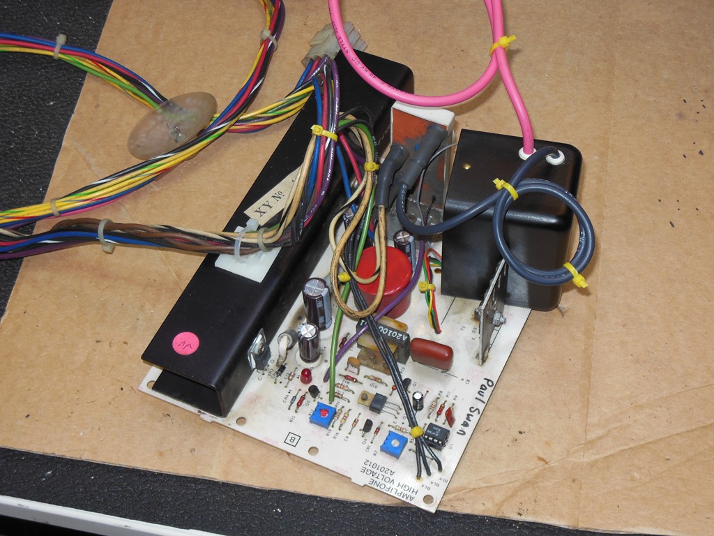
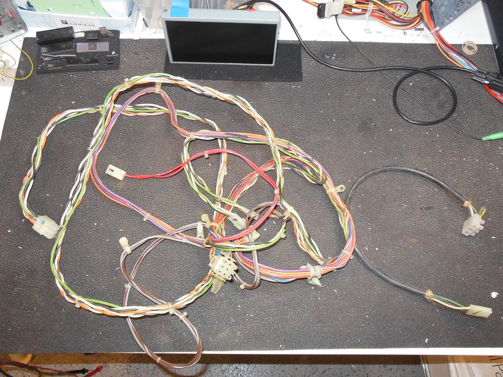
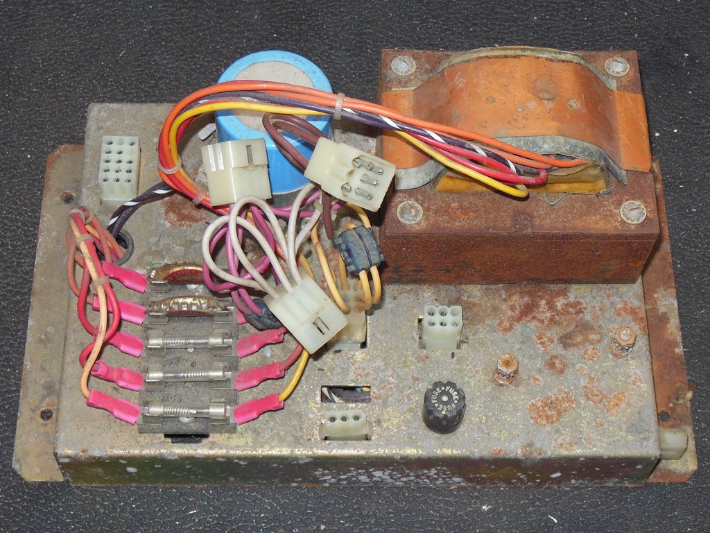
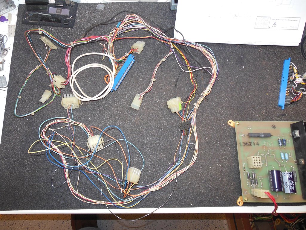
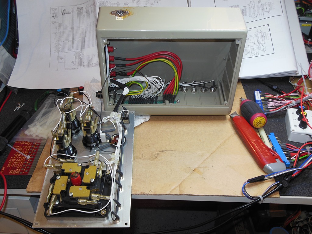
08/06/2015 - Wiring & brick assessment
The last few weeks had made it abundantly clear that I needed to get Star Wars
boards on the bench for testing & repair. To do that with this game needs a none trivial
test fixture constructing to be able to provide the odd power requirements and a useable
vector display. The starting point for this was the old hacked up wiring loom from the
Konami GT conversion that I'd replaced with a complete original reclaimed one as part of
the game restoration.
The AC side of the loom looked pretty much wholly intact. The power cord had been
hacked but I could live with a short cord for a test fixture. The DC side of the loom was
in worse shape. All the ARII connectors except for the speaker were there but the rest of
the wiring was of course cut out and wired to the Konami connector.
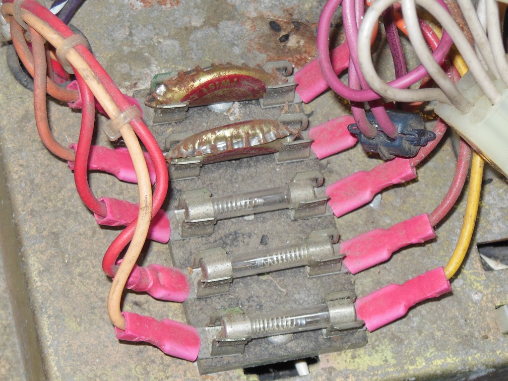
To go with the wiring loom I needed an Atari power brick. I didn't have a spare colour
vector brick so I looked into using an Asteroids brick. This had the right low AC voltages
but the wrong voltages for the vector monitor. Since I wasn't planning on using those in the
short term I decided to try it. However, this Asteroids brick looked pretty rough and in
unknown condition with bottle cap fuses. Further, Atari put a key pin on the Star Wars
connector to prevent accidental use of the wrong supply. To utilize an Asteroids supply I'd
need to either change the pins or build an adaptor. I decided instead to pull the Star Wars
brick out of my cabinet and acquire a second colour vector brick to dedicate to the test
fixture at a later date.
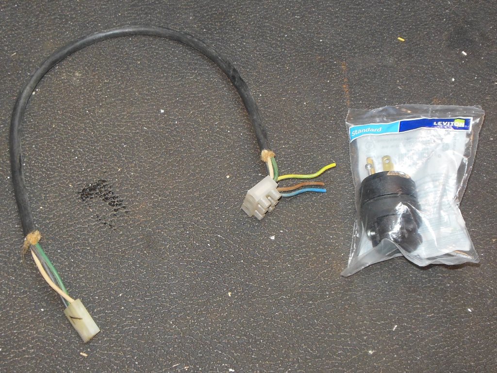
02/07/2015 - Power up
The only work needed on the AC side wiring was fitting a power plug to the mains input
cable. I had a spare untested ARII to use for the test fixture. The ARII was already missing
the R29 sense resistor so I completed the sense mod on it before powering it up. I used my
ARII dummy load and LED indicator board built previously to test out the ARII. The +5V
looked good and properly adjusted to +5.1V. +22V and -22V were also both present and looked
good. -5V and +12V however were both missing and thus some further repair work was needed.
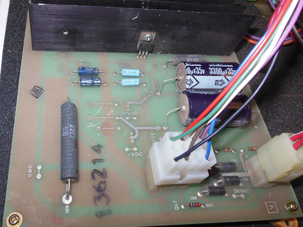
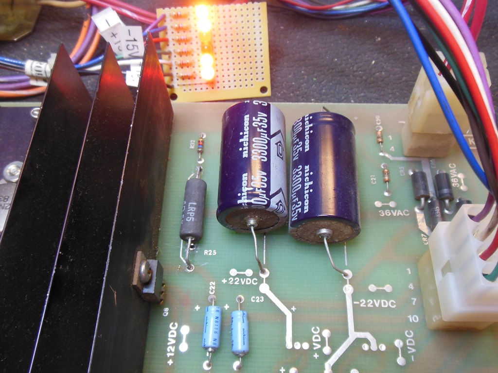
06/07/2015 - ARII repairs
The problem with the missing -5V was easy to see - the -5V regulator, Q9, had been
robbed from the board. Since the negative voltage regulators do not have ground on the tab
I also needed to find an insulation sheet and plastic screw with which to fit a new 7905CV.
With a new regulator fitted the -5V appeared fine and attention turned to the +12V.
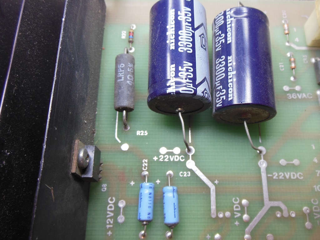
This one was a little odd. The unregulated DC measured on both sides of R25 OK but there
was no input to the 7812 at Q8. According to the schematic this is a direct connection so
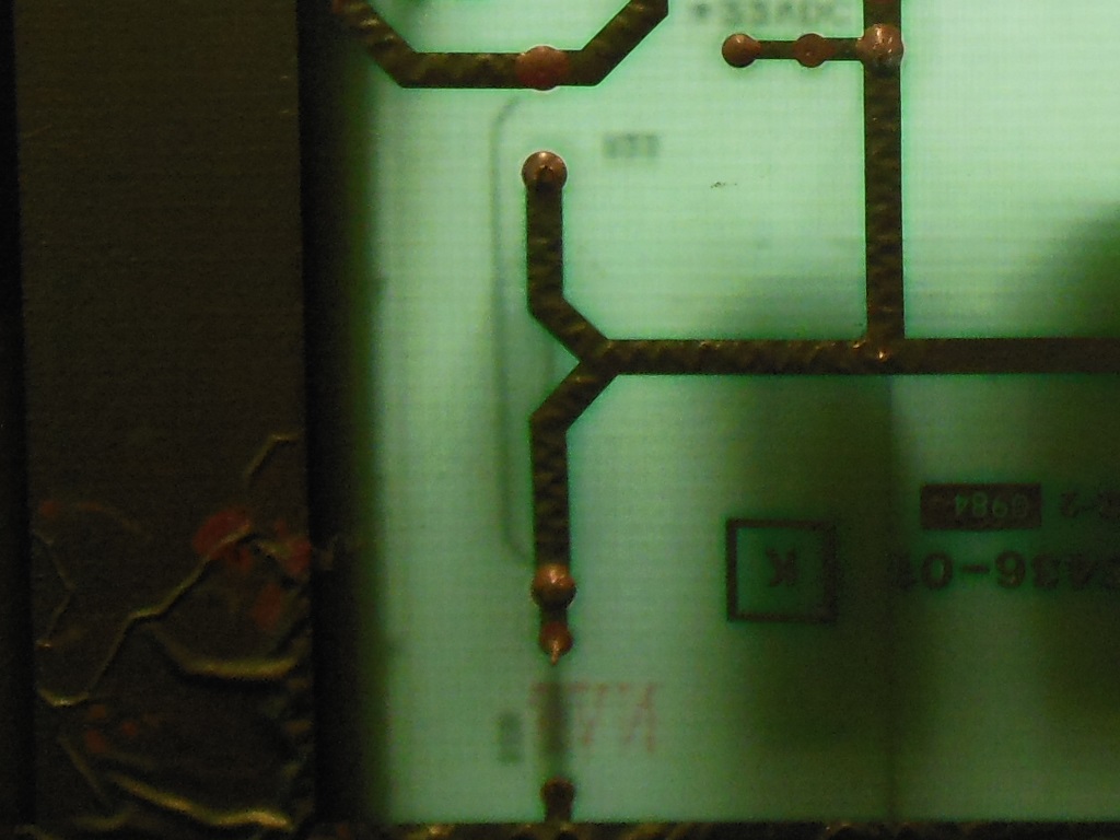
attention turned to the tracking between R25 and Q8. On the back of the PCB the tracking
for R25 didn't make sense - both sides of R25 were tracked together. Looking carefully at
the front identified the problem - a factory manufacturing error had R25 loaded into the
wrong pins resulting in no +12V. I wasn't sure if this ARII had ever been used in a game or
what game that might have been but it had had no +12V from the factory. Removing R25,
reforming the pins to properly fit it in the correct location and refitting it brought
back the +12V and the ARII ran fine for a few hours with no further issues.
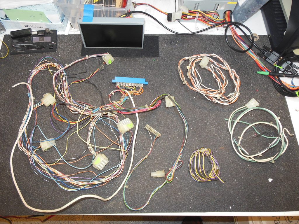
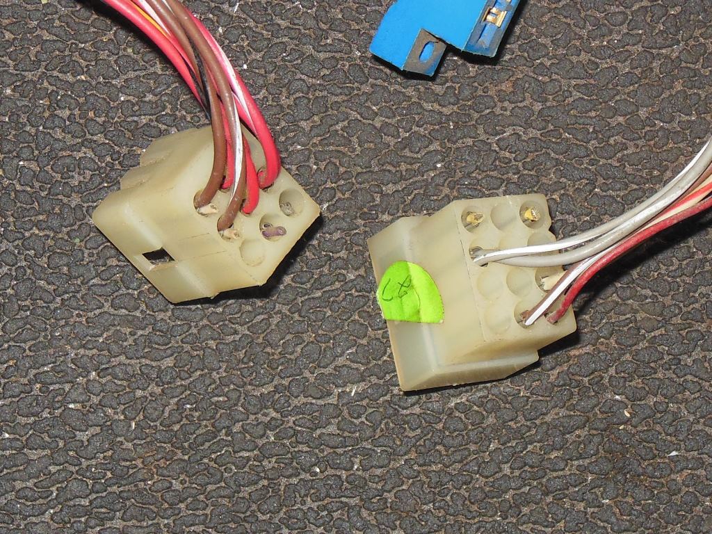
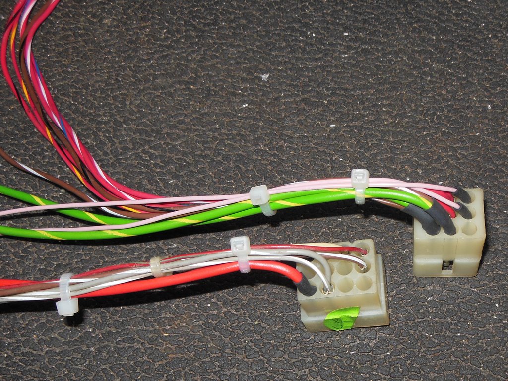
12/07/2015 - DC wiring
The hacked up DC side from the Konami GT conversion had most of the wiring to the
ARII still intact but there were some connections (unused on Konami GT) that had been cut
and needed repairing to restore them (duplicates for the second connector and the
+/-22V outputs, for example).
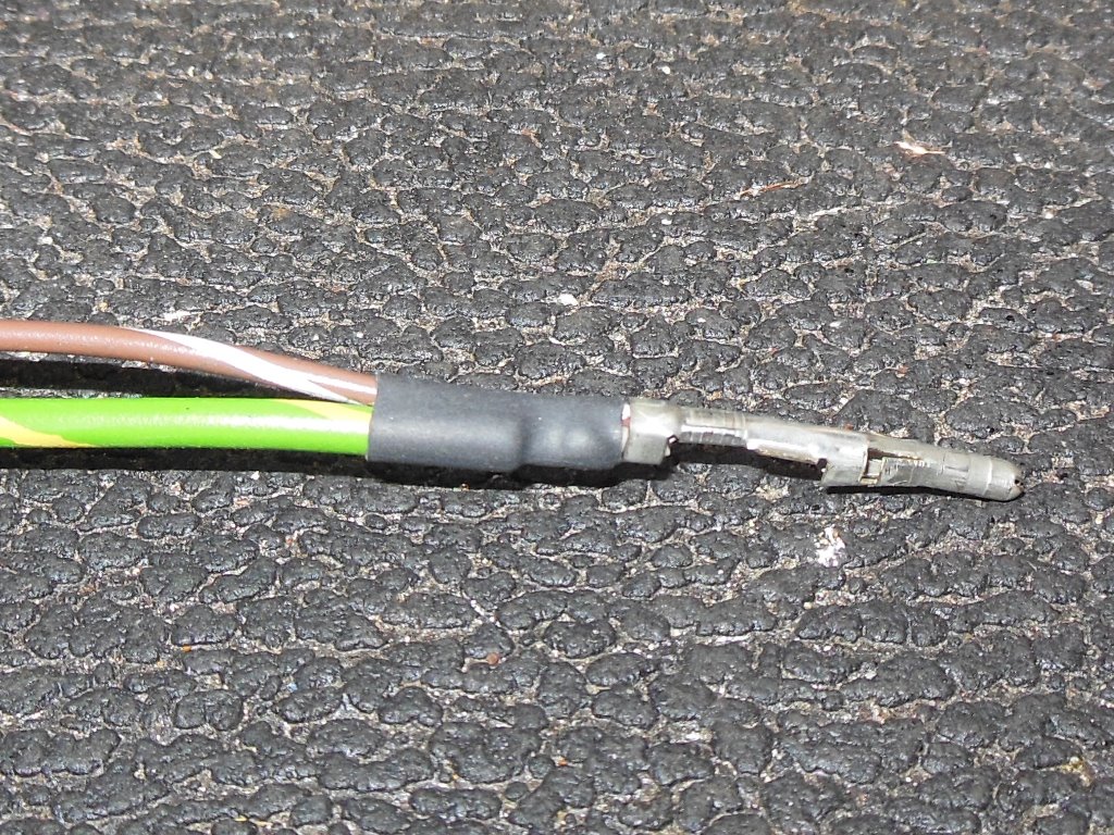
Using a jewelers screwdriver I was able to pop out the pins and solder a new wire onto
the remaining stub to reconnect the missing wire. Sealing with shrink wrap tubing provided
some strain relief.
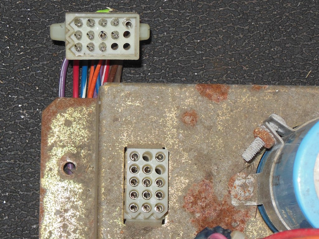
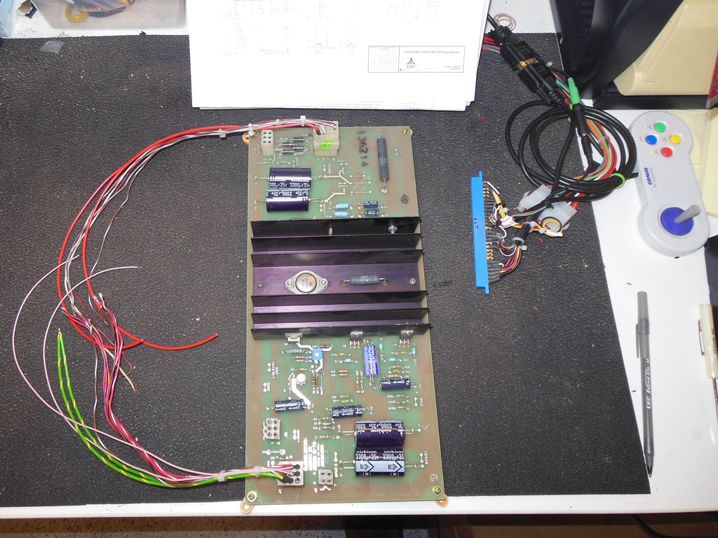
15/07/2015 - Board power
With the ARII wiring fixed the two edge connectors for the Star Wars boards could now
be wired in. The second smaller edge connector is an odd size but I managed to find some
on eBay.
First power on yielded no vector output at all. Poking around with a scope isolated
the problem down to the reset line being stuck. Tracing that back revealed that Star
Wars uses the unregulated 10.3VDC to drive the reset circuitry. In the cabinet the
10.3VDC is connected through to the power brick via the coin door and utility panel wiring
loom. The plan of action for this was to fit the 10.3V test point on the ARII and then use
a fly lead with a spade connector to hook it up.
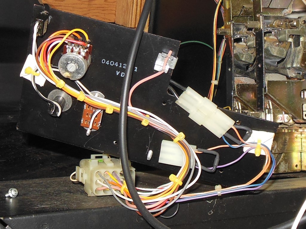
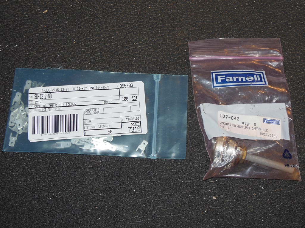
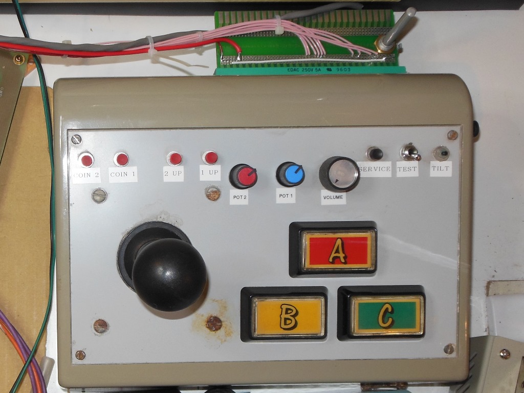
19/07/2015 - Board signals
Neither the schematic or parts list showed the actual value of the volume control pot
so I had to find out the value from the one fitted to the actual cabinet. It was a dual
gang 10K Ohm unit. As luck would have it I had a new one of those (well, NOS I
suppose since it was from Farnell about 20 years ago, made in England no less).
For the 10.3VDC test point the right part was a Keystone 1212 "tab" spade terminal
available from Digikey.
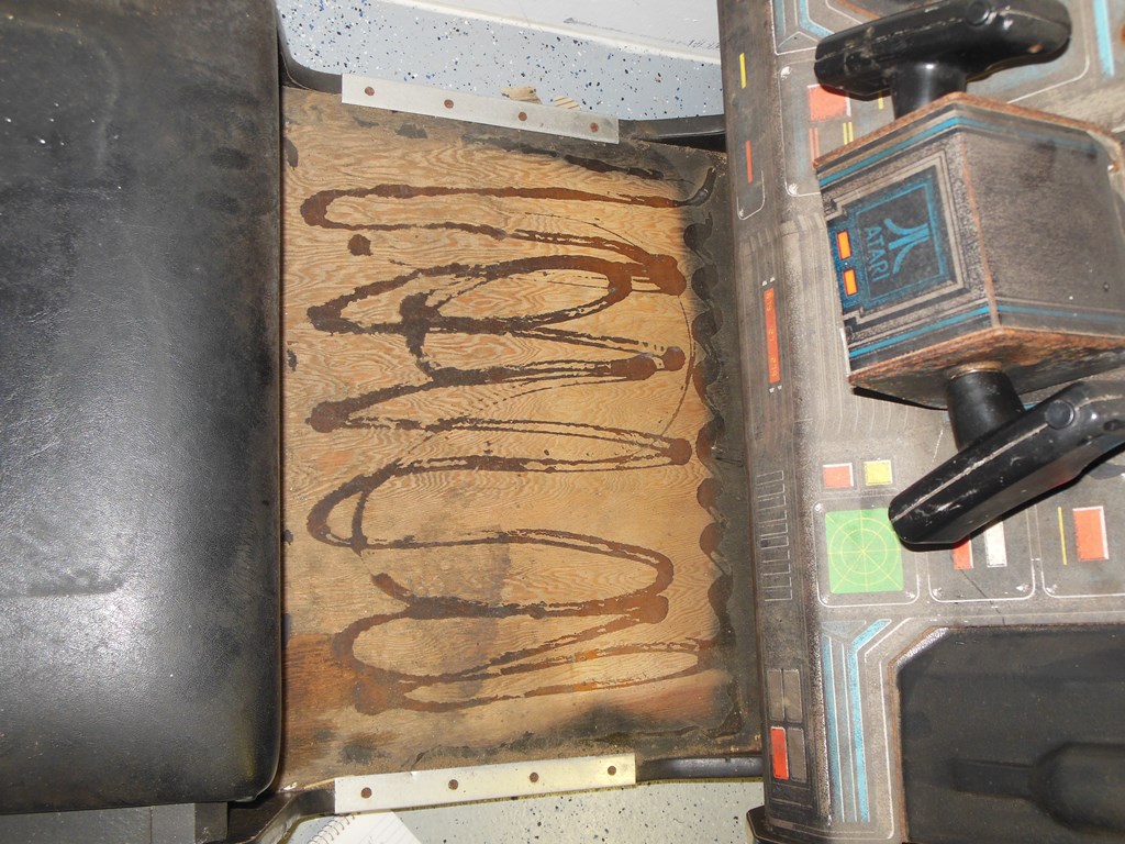
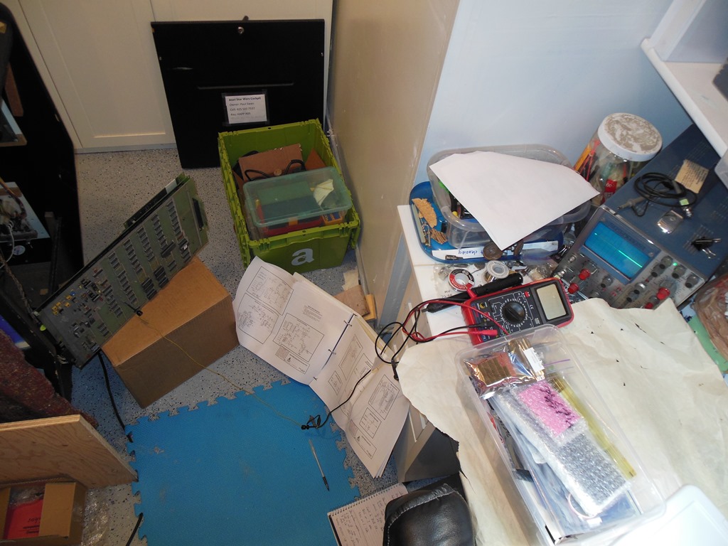
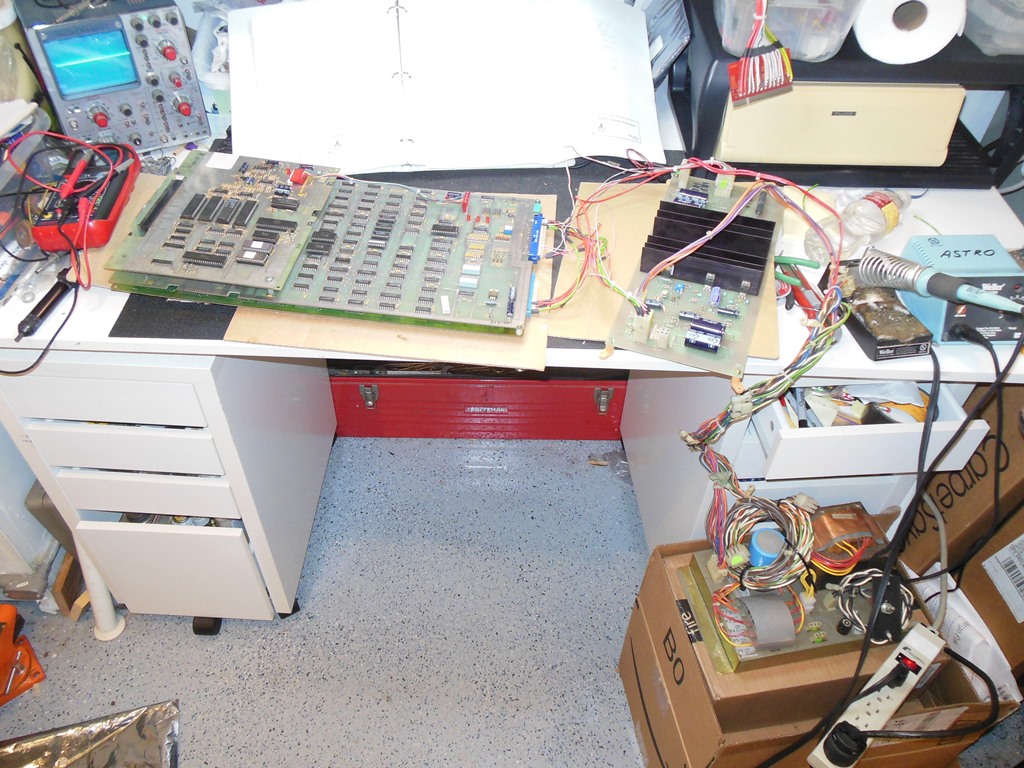
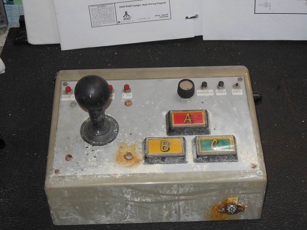
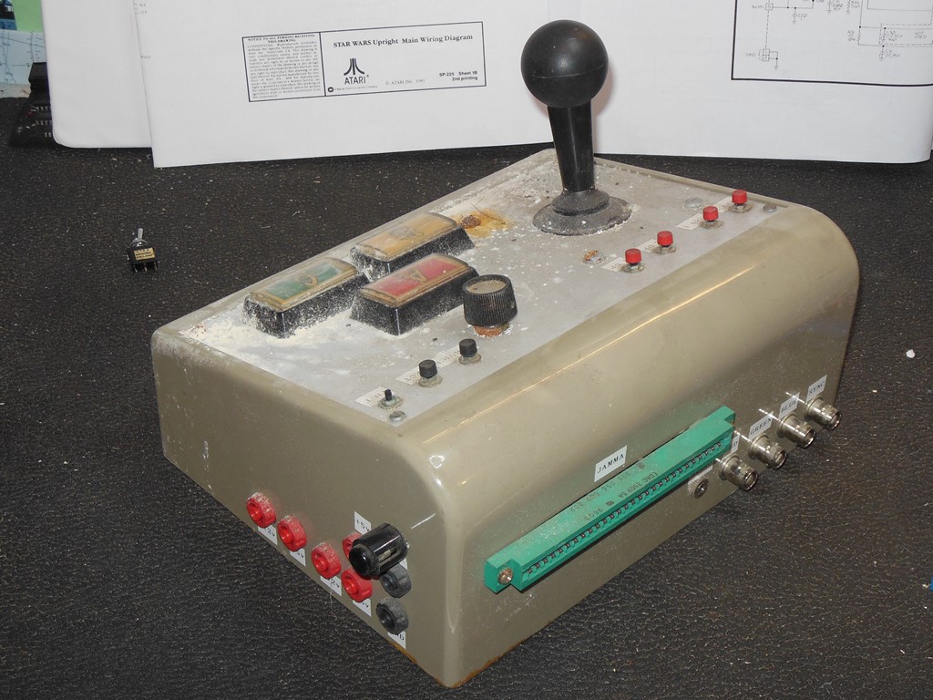
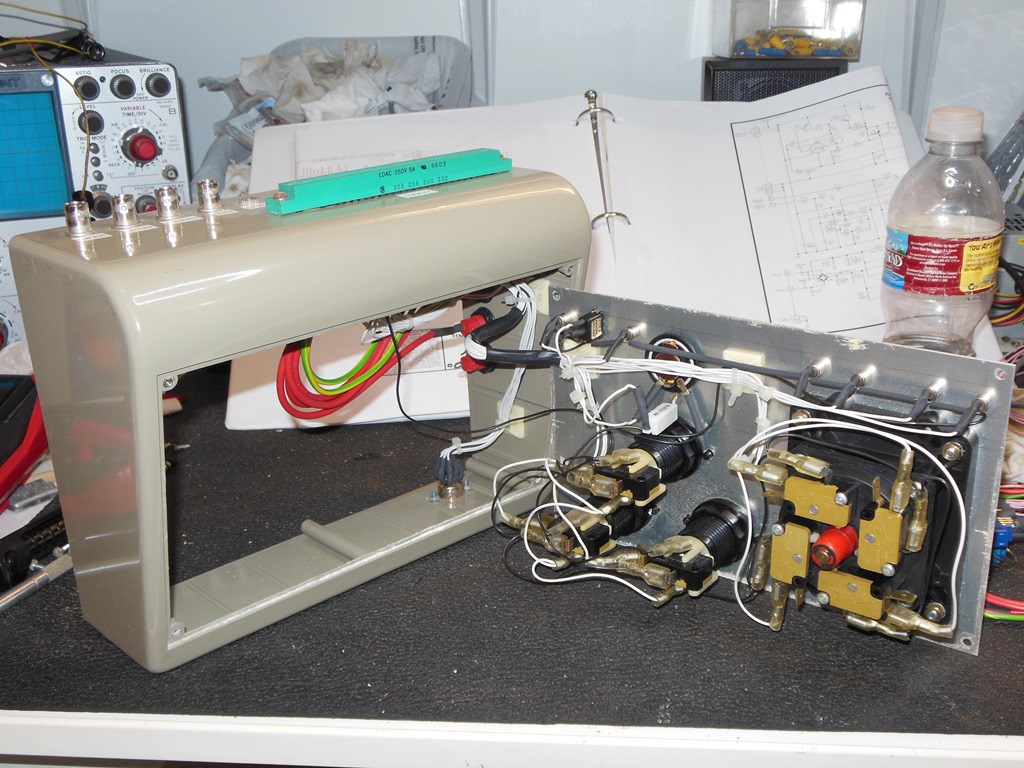
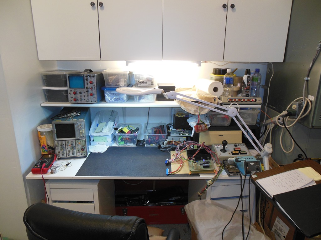
For the control inputs (coin, buttons, test, service etc.) I dug out my old JAMMA
test box that I used to use in England. It'd been on my test bench in my old English
warehouse for a decade and during that time a roof leak had wrecked most of the bench
area, hence it's distressed state. The plan was to wire up the Star Wars controls to
a JAMMA adaptor and plug it into this. There was a small modification required first
- to change the test button into a test switch.
20/07/2015 - Board repair, RGB output
With the board now running something it was time to actually start trying to fix it.
The X and Y outputs looked OK on the scope but the RGB outputs were very low, just
fractions of a volt. This confirmed that the no picture was a board issue and not a
problem with the monitor. Looking at the ZREF line showed it was idle. Attention
turned to 8F pin 4 (DAC08 output). This was 0V all the time. Looking at the inputs
to the DAC showed they were a constant value in test mode and active in game mode.
However, in both cases the output from the DAC was 0V. Checking VR+ showed it to be
active. Checking the op-amp output at 9F pin 1 (TL082) showed it was a static ~1.8VDC.
It looked like either the DAC was bad or the op-amp after it was clamping its output.
I decided to simply change both and doing so brought back a healthy looking RGB output
on the scope.
24/07/2015 - Board repair, matrix errors
Attention turned to the matrix errors on the main board.
The Star Wars Troubleshooting Guide contains a full explanation of the self-tests
and how to interpret the results. The failure display strings represent the dip switch
encoding required to activate the test along with the received value from the hardware,
so in my case:-
| Test String | Test No. | Rec. Value |
| NNNF NFFF | 18 | FE55 |
| NNNF NFNF | 20 | 00AA |
Correlating the results with the guide gave the full set of test information for this
set of matrix tests:-
| Test No. | Equation (A - B) x C | Exp. Value | Rec. Value |
| 17 | (5555 - 0000) x 4000 | = 5555 | OK |
| 18 | (0000 - 5555) x 0000 | = 5555 | = FE55 |
| 19 | (2AAA - 0000) x 4000 | = 2AAA | OK |
| 20 | (0000 - 2AAA) x C000 | = 2AAA | = 00AA |
As can be seen from the full table we can conclude that not all the matrix tests are
failing - the test fails only if the second subtract value is none-zero. This value
corresponds to the value loaded in Register B (i.e. the test fails when Register B
is none-zero).
Poking around with the scope showed that all the inputs to all the registers,
6A,7A,6B,7B, (LS165) looked OK and all the outputs were active. The same was true at the
subtractor at 8B (LS385). Since this circuit has relatively few outputs due to its serial
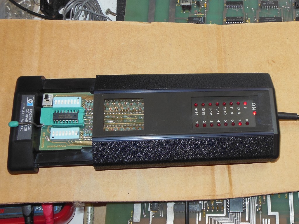
nature it's not easy to observe the effects of bad inputs on a simple scope. I
setup my HP 10529A comparator for LS165 and compare tested the four LS165's that make up
Registers A & B:-
- 6B - Failed on pins 6 & 7.
- 7B - OK
- 6A - OK
- 7A - OK
I double checked the compare results but still had the same outcome indicating 6B (LS165)
was bad. Replacing 6B and retesting gave an all-pass on the self-test and game mode looked
good on the XY scope :)
For future reference I noted that my Star Wars board did not have TI 74LS384 or 74LS385
fitted but AMD devices thus:-
- TI 74LS384 == AMD AM25LS14
- TI 74LS385 == AMD AM25LS15
The equivalence doesn't help much as both parts are hard to find :|
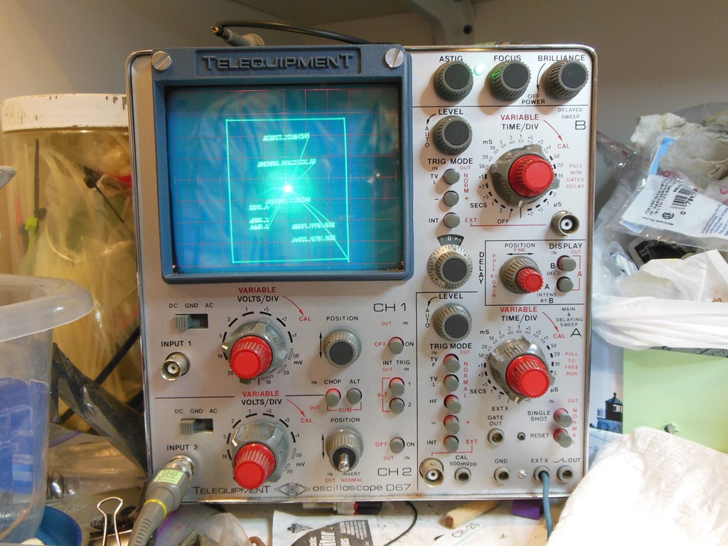
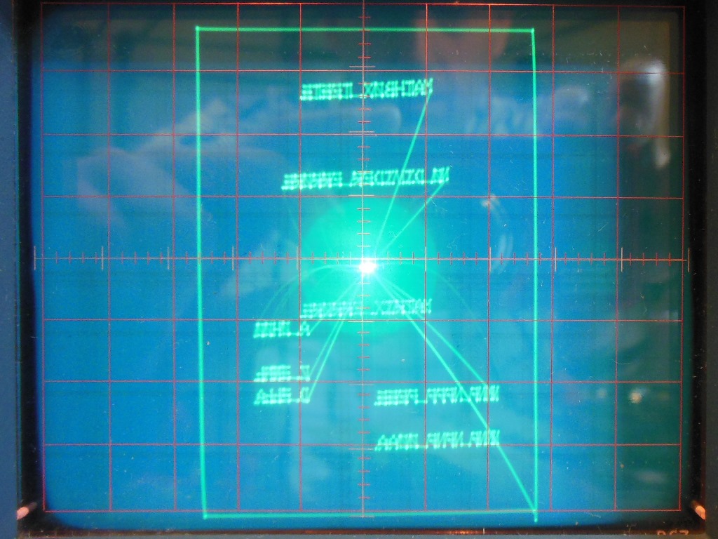
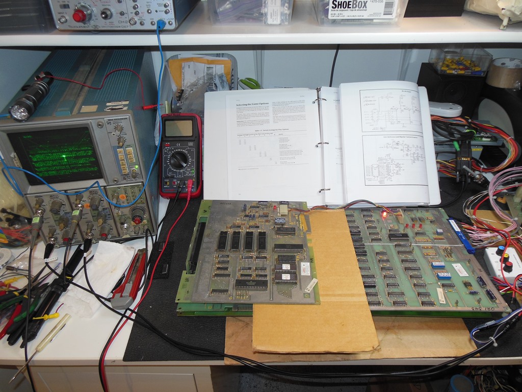
05/08/2015 - Oscilloscope #2
To properly continue working vector boards needed a bench friendly vector display
to verify the picture output. The display on the Telequipment D67 wasn't that great and
I needed a way to see both the vector display and have an oscilloscope at the same time.
The solution was to dig out and repair my old Tecktronix 7603 large screen oscilloscope
that I'd brought from the UK.
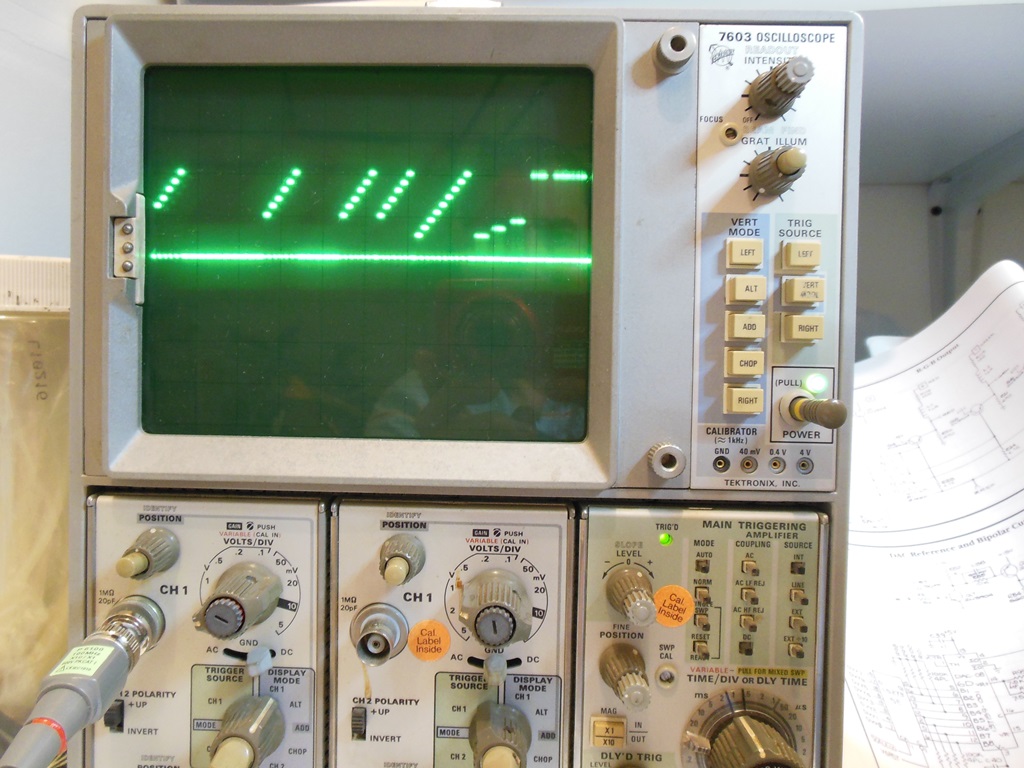
10/08/2015 - Tektronix 7603 XY display
I completed the wiring for the test harness to add oscilloscope friendly BNC connectors
for X & Y outputs. I also built a small Z RGB amplifier & inverter to be able to drive the
Z input on the scope. All connected the picture was pretty reasonable and good enough to be
able to see the self-test text.
Since the exact RGB intensity was still hard to see on this setup I took a reference
trace of the typical RGB output for the intensity test display - this trace is far more
useful than the actual visual on-screen intensity because it clearly shows the intensity
steps in the display output.
29/08/2015 - More board repairs
The main board I'd been using so far was on loan from a friend that I needed to return
now that I'd fixed it's matrix problem. It was time to get some more of my own boards on
the bench with a target to get two complete working sets out of a collection of three faulty
sets. My friend had already made significant headway on the sound & AVG boards but got
bogged down in math box problems on the main boards.
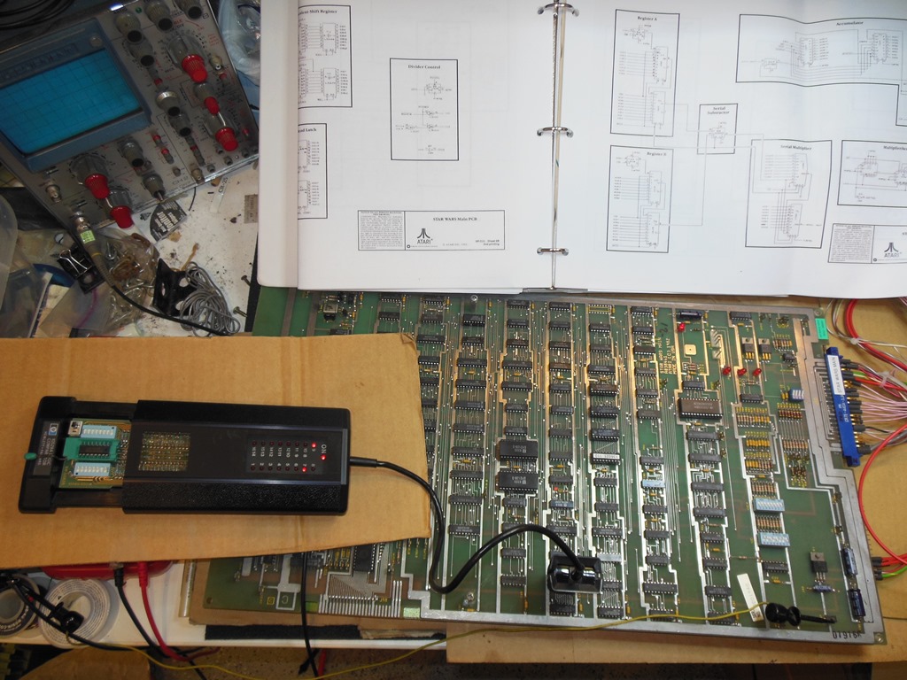
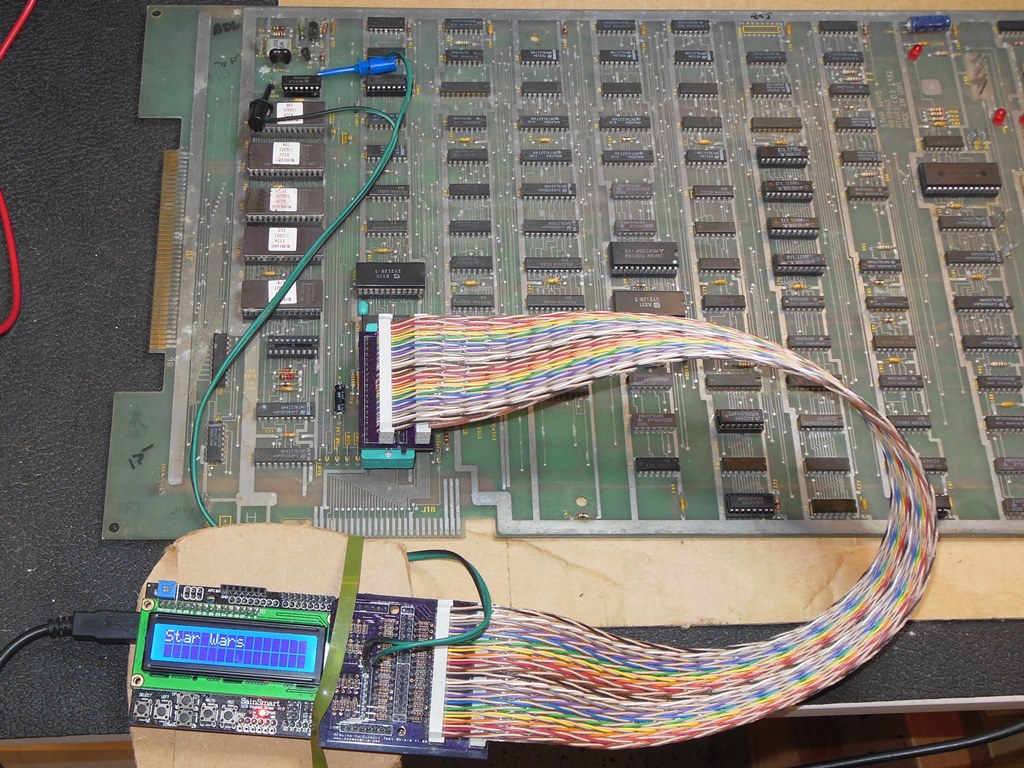
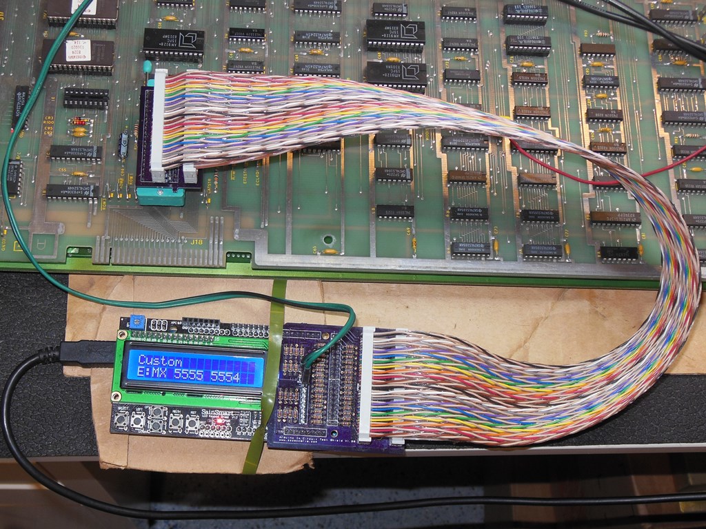
13/09/2015 - Arduino ICT support for 6809E & Star Wars
It became pretty clear pretty quickly that the two built in self-test options were not
going to be as helpful as Atari must have thought they would be (at least without setting
up a full multi-bit logic analyser). As far as I could tell the two options were:-
- The standard full self-test that loops through all of the tests and displays
the results on screen continuously.
- The option switch based individual test one-shot run after reset.
What I really needed was something that could loop a single test continuously or one shot
a test quickly. I decided that to make headway with the math box I needed more control over
the circuits in question and decided to invest some time into adding 6809E and
Star Wars support to my existing Arduino In Circuit Tester widget:-
Arduino Mega In Circuit Tester
The Arduino ICT page describes this side-project.
20/09/2015 - Matrix repairs
Star Wars CPU 'PS2'
This CPU board was the first one on the bench. Physically it was very badly corroded and
my friend had already done some work to get the CPU sub-system booting but with both divider
& matrix errors. I started on this one before I'd decided to do the Arduino work above and it
was working on this board that triggered that activity :(
I started out looking at the matrix problems since I already had some familiarity with it
from the first repair. I didn't get very far before the board started intermittently crashing
and then died completely. There was no activity on the CPU at all, including the CPU 'E' clock
input. The output of the clock divider 2N (LS161) was erratic but the 12MHz clock input at
pin 2 of IC 2N looked OK on the scope. Suspecting IC 2N was bad I replaced it but it made no
difference.
Looking again at every pin on IC 2N revealed input pin 10 was all over the place - hovering
around various DC levels and with a clock-like signal over the top. From the schematics this
was supposed to be a simple pullup, PR96. This signal state was confirmed as not a mistake at
pin 1 also - for sure pullup net PR96 was bad :( Since the pullup net connects to many points
I decided to defer on finding this problem by connecting the pullup directly to Vcc to both
be able to make further progress and hope that the faulty signal driving onto it would burn
out.
Now back looking at the matrix problems and the first failing test, "NNNO ONON". This is
a simple test of load/store on the accumulator, "LAC M(00), SAC M(01), HALT", suggesting that
the basic path to and from the accumulator & memory was bad.
Breaking out the Arduino ICT revealed that the RAM 5F & 5H test was intermittently failing
as the board warmed up after power on, e.g. "52C7 F8 FA" and "52FB F9 FB" that indicated bit 1
was bad. These RAMs are arranged as a 16-bit bus in an odd-even fashion for the 6809E thus:
| 5F | B | AB0=0 | Even |
| 5H | A | AB0=1 | Odd |
Therefore, from the failing odd addresses 5H was bad. Swapping 5H revealed a bad contact on 5H
or the 5H socket was bad. Moving on for now, the ROM test failed for ROM 1M and a ROM read returned
bad data. Tracing through with a scope revealed that ~ROM4 was not active but ~ROM3 was active.
Tracing back to pin 8 of IC 2K (LS08) as low with pin 9 high and pin 10 low. Pin 10 was a pullup,
R94, but during a ROM read some other signal was present on it. This was another bad pullup and
again temporarily tying to Vcc fixed the ROM read problem :(
After the discovery of the second failed pullup net I decided to go over all the pullups on the
board and verify their state:
| Pullup | State | Resistance |
| R93 | High | Short to Vcc |
| R92 | High | 1K |
| R95 | High | 1K |
| R97 | High | 1K |
The remaining pullups were high with one of them a dead short to Vcc bringing the total number
of bad pullup nets to three.
Given the rusty condition of the board, the bad state of the sockets, the multiple failed pullup
nets and still with problems in both the divider & matrix circuits I decided to abandon this board
as a parts donor board beyond economic repair :(
Star Wars CPU 'PS1'
This board looked more promising. Testing out with the Arduino ICT showed ROM & RAM tests OK,
divider tests OK but with matrix errors to fix:
| Test No. | Equation (A - B) x C | Exp. Value | Rec. Value |
| 17 | (5555 - 0000) x 4000 | = 5555 | = 5554 |
| 18 | (0000 - 5555) x 0000 | = 5555 | = 5554 |
| 19 | (2AAA - 0000) x 4000 | = 2AAA | = 2AA9 |
| 20 | (0000 - 2AAA) x C000 | = 2AAA | = 2AA9 |
The pattern suggested that the result is short by 1. A compare test on the 4 x LS165 A/B register
latches didn't show any issues (I didn't really expect any since the short by one error seemed
more likely to be in the multiply/subtract stage).
Using the serial capture feature of the Arduino ICT I captured the serial stream into and out
of the serial subtract IC for Test 17:
| IC | Pin | Exp. Value | Rec. Value |
| 8B | 1 | ff fc 00 00 - 00 01 ff ff | ff fc 00 00 - 00 01 ff ff |
| 8B | 6 | 00 00 00 02 - aa a8 00 00 | 00 00 00 00 - aa a8 00 00 |
| 8B | 7 | 00 00 00 00 - 00 00 00 00 | 00 00 00 00 - 00 00 00 00 |
| 8B | 9 | 00 00 00 01 - 55 54 00 00 | 00 00 00 00 - 55 54 00 00 |
| 8B | 12 | 00 01 55 54 - 00 00 00 00 | 00 01 55 54 - 00 00 00 00 |
| 8B | 14 | 00 00 00 00 - 00 00 00 00 | 00 00 00 00 - 00 00 00 00 |
| 8B | 15 | 1f fe aa a8 - 00 00 00 00 | 1f fe aa a8 - 00 00 00 00 |
At the time I didn't have known good expected captures since I had no working boards however it
was easy to see from the captures that a bit was missing coming out of the serial multiplier
going into the 2nd stage subtract IC at pin 6. Further, the input to the multiplier from the 1st
stage subtract looked OK. Suspecting a bad multiplier, verification with the comparator
identified IC 6C (27LS14) as bad and IC 7C (27LS14) as OK. Changing IC 6C fixed the board
and then I took the known good expected captures illustrated in the table above.
Star Wars CPU 'PS5'
Setting this board up for the Arduino ICT and testing detected a number of issues:
- The LED CR2 was not lit.
- The ~RESET line did not fire after power on.
- The ROM test failed CRC with ROM 1JK reporting 0xf6da0a00.
- Matrix tests 18 & 20 failed.
Starting with the LED CR2, the LED had 1.0V across it but was not lit. Replacing the LED CR2
fixed the issue.
Moving on to the lack of power on reset, pin 11 of IC 10R (LS14) transition hi->lo as expected
when the 10.3VDC line was unplugged. Pin 12 of IC 6E was active. At this point, the failure mode
changed and the reset line became stuck active. Pin 13 of IC 2P (LS393) looked OK. Pins 13, 12 & 11
of IC 2N (LS161) all looked good and active. However, pins 6 & 8 on IC 2P (LS393) were both stuck
low. I suspected a bad IC 2P however verification with the comparator did not flag IC 2P as bad.
Looking at all the pins on IC 2P found unconnected pin 10 clamped, strongly suggesting pin IC 2P
was bad. Changing IC 2P (LS393) fixed the reset problems.
Checking the CRC for the ROM test failure with MAME confirmed that the board simply had a
different ROM revision.
The matrix tests reported the following:
| Test No. | Equation (A - B) x C | Exp. Value | Rec. Value |
| 17 | (5555 - 0000) x 4000 | = 5555 | OK |
| 18 | (0000 - 5555) x 0000 | = 5555 | = 1555 |
| 19 | (2AAA - 0000) x 4000 | = 2AAA | OK |
| 20 | (0000 - 2AAA) x C000 | = 2AAA | = 0AAA |
This was by now a familiar pattern where if only 2 of the 4 tests fail with missing bits there
is a good chance it's the A/B registers (IC's 6A/7A and 6B/7B). Verification with the comparator
identified IC 6B (LS165) as bad. Replacing IC 6B fixed the matrix errors :)
27/09/2015 - Board testing
A few hours of burn in testing of the two complete working sets didn't yield any further
failures :)
06/10/2015 - Analog input test setup
The now working CPU board 'PS1' was labelled as "bad analog input". In test mode, the
menu options cycled through suggesting the analog input was stuck down in some way.
I didn't have my test control box setup for analog inputs so first I needed to add a couple
of pots to the box routed through to two unused pins on the JAMMA connector. Then I added
connections for those into the Star Wars test wiring loom. Further, I added support for reading the
analog inputs to the Arduino ICT. With all that done, the analog inputs were confirmed as not
working. Replacing the ADC at 9K with one from the scrap board fixed the input and fixed the
game (it was playable with pots).
24/10/2015 - Final assembly & test
Finally, after taking the whole summer get the boards all fixed up, the game could be
put back together. Since this game board set had never been used before in this cabinet it
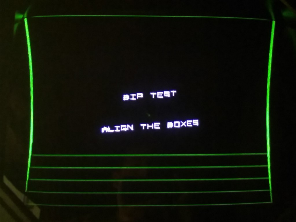
needed the game options setting up and the BIP calibrating. With that done and after the
monitor had been given a couple of hours to warm up I setup the Amplifone by following the
instructions in the monitor manual. The picture is pretty good given that the CRT has seen
better days. We played a few games :)
Star Wars Maintenance 2017
Star Wars Maintenance 2018
Star Wars Maintenance 2019
Star Wars Maintenance 2022
Star Wars Maintenance 2024
prswan@gmail.com